EP4318420A1 - Bill processing device and failure determination method - Google Patents
Bill processing device and failure determination method Download PDFInfo
- Publication number
- EP4318420A1 EP4318420A1 EP21932902.6A EP21932902A EP4318420A1 EP 4318420 A1 EP4318420 A1 EP 4318420A1 EP 21932902 A EP21932902 A EP 21932902A EP 4318420 A1 EP4318420 A1 EP 4318420A1
- Authority
- EP
- European Patent Office
- Prior art keywords
- unit
- vibration
- field repair
- failure
- frequency
- Prior art date
- Legal status (The legal status is an assumption and is not a legal conclusion. Google has not performed a legal analysis and makes no representation as to the accuracy of the status listed.)
- Pending
Links
Images

Classifications
-
- G—PHYSICS
- G07—CHECKING-DEVICES
- G07D—HANDLING OF COINS OR VALUABLE PAPERS, e.g. TESTING, SORTING BY DENOMINATIONS, COUNTING, DISPENSING, CHANGING OR DEPOSITING
- G07D11/00—Devices accepting coins; Devices accepting, dispensing, sorting or counting valuable papers
- G07D11/20—Controlling or monitoring the operation of devices; Data handling
- G07D11/22—Means for sensing or detection
- G07D11/235—Means for sensing or detection for monitoring or indicating operating conditions; for detecting malfunctions
-
- G—PHYSICS
- G07—CHECKING-DEVICES
- G07D—HANDLING OF COINS OR VALUABLE PAPERS, e.g. TESTING, SORTING BY DENOMINATIONS, COUNTING, DISPENSING, CHANGING OR DEPOSITING
- G07D11/00—Devices accepting coins; Devices accepting, dispensing, sorting or counting valuable papers
- G07D11/40—Device architecture, e.g. modular construction
-
- B—PERFORMING OPERATIONS; TRANSPORTING
- B65—CONVEYING; PACKING; STORING; HANDLING THIN OR FILAMENTARY MATERIAL
- B65H—HANDLING THIN OR FILAMENTARY MATERIAL, e.g. SHEETS, WEBS, CABLES
- B65H2511/00—Dimensions; Position; Numbers; Identification; Occurrences
- B65H2511/50—Occurence
- B65H2511/52—Defective operating conditions
-
- B—PERFORMING OPERATIONS; TRANSPORTING
- B65—CONVEYING; PACKING; STORING; HANDLING THIN OR FILAMENTARY MATERIAL
- B65H—HANDLING THIN OR FILAMENTARY MATERIAL, e.g. SHEETS, WEBS, CABLES
- B65H2515/00—Physical entities not provided for in groups B65H2511/00 or B65H2513/00
- B65H2515/50—Vibrations; Oscillations
-
- G—PHYSICS
- G07—CHECKING-DEVICES
- G07D—HANDLING OF COINS OR VALUABLE PAPERS, e.g. TESTING, SORTING BY DENOMINATIONS, COUNTING, DISPENSING, CHANGING OR DEPOSITING
- G07D2211/00—Paper-money handling devices
Definitions
- the present invention relates to a bill handling apparatus and a failure determination method.
- Some kinds of bill handling apparatuses such as automatic teller machine, include a field repair unit that is individually replaceable.
- the field repair unit include a money receiving/paying unit that performs reception and payment of bills, a storage unit that temporarily stores bills, storage cassettes that store bills by denomination, and the like.
- Patent Literature 1 JP-A-2011-008336
- a bill handling apparatus in the present application includes a field repair unit, a sensor and a determining unit.
- the sensor detects a vibration of the field repair unit.
- the determining unit determines whether there is a failure in the field repair unit based on the vibration.
- a failure of a field repair unit can be detected.
- FIG. 1 is a diagram illustrating a configuration example of a bill handling apparatus of a first embodiment of the present disclosure.
- a bill handling apparatus 1 includes a money receiving/paying unit 3 that receives and pays a bill 2, a first storage unit 4 that temporarily stores the bill put by the money receiving/paying unit 3, a discriminating unit 5 that discriminates the bill transferred from the first storage unit 4, and a second storage unit 6 that temporarily stores the bill 2 transferred from the discriminating unit 5.
- the bill handling apparatus 1 includes a returning unit 7 that stores the bill 2 transferred from the discriminating unit 5, and that returns the bill 2 by ejecting therefrom, and a rejecting unit 8 that stores the bill 2 that has abnormal thickness or length, the bill 2 that is damaged, and the like.
- the bill 2 that is put in from the money receiving/paying unit 3 is stored in the first storage unit 4, and then discriminated by the discriminating unit 5.
- the bill 2 from which something abnormal is detected is transferred from the discriminating unit 5 to the rejecting unit 8 to be stored therein.
- the bill 2 from which nothing abnormal is detected by the discriminating unit 5 is stored in the second storage unit 6.
- the bill 2 stored in the second storage unit 6 is transferred to the money receiving/paying unit 3, and is returned from the money receiving/paying unit 3.
- the bill stored in the second storage unit 6 is transferred to the first storage unit 4, and is transferred from the first storage unit 4 to the discriminating unit 5, and is then transferred from the discriminating unit 5 to the returning unit 7, and is stored in storage cassettes 7a, 7b, 7c, and 7d of the returning unit 7 by denomination.
- the bill 2 stored in the returning unit 7 is dispensed, the bill 2 stored in the returning unit 7 is transferred from the returning unit 7 to the discriminating unit 5, and is then transferred from the discriminating unit 5 to the second storage unit 6 to be stored in the second storage unit 6.
- the bill 2 that is stored in the second storage unit 6 is transferred to the money receiving/paying unit 3, and is dispensed from the money receiving/paying unit 3.
- Each of the money receiving/paying unit 3, the first storage unit 4, the second storage unit 6, the storage cassettes 7a to 7d, and the rejecting unit 8 is one example of the field repair unit individually replaceable.
- Each of the money receiving/paying unit 3, the first storage unit 4, the second storage unit 6, the storage cassettes 7a to 7d, and the rejecting unit 8 includes a conveyance roller to convey the bill 2, and a conveyance motor to drive the conveyance roller. Because each of the money receiving/paying unit 3, the first storage unit 4, the second storage unit 6, the storage cassettes 7a to 7d, and the rejecting unit 8 has the conveyance motor, vibrations occur when the conveyance motor rotates.
- a vibration detection sensor 51A is mounted, to the first storage unit 4, a vibration detection sensor 51B is mounted, to the second storage unit 6, a vibration detection sensor 51C is mounted, and to the rejecting unit 8, a vibration detection sensor 51H is mounted.
- a vibration detection sensor 51D is mounted, to the storage cassette 7b, a vibration detection sensor 51E is mounted, to the storage cassette 7c, a vibration detection sensor 51F is mounted, and to the storage cassette 7d, a vibration detection sensor 51G is mounted.
- the bill handling apparatus 1 includes a determining unit 52.
- the money receiving/paying unit 3, the first storage unit 4, the second storage unit 6, the storage cassettes 7a to 7d, and the rejecting unit 8 can be collectively referred to as "field repair unit”.
- the vibration detection sensors 51A to 51H can be collectively referred to as “vibration detection sensor 51".
- the determining unit 52 is implemented by, for example, digital signal processor (DSP), a field programmable gate array (FPGA), or the like as hardware.
- DSP digital signal processor
- FPGA field programmable gate array
- the respective vibration detection sensors 51 mounted on the respective field repair units detect vibrations of the respective field repair units continuously over time, and outputs chronological data indicating values of vibrations (hereinafter, referred to as "vibration data" in some cases) to the determining unit 52.
- the vibration detection sensor 51A outputs vibration data of the money receiving/paying unit 3 to the determining unit 52
- the vibration sensor 51B outputs vibration data of the first storage unit 4 to the determining unit 52
- the vibration detection sensor 51C outputs vibration data of the second storage unit 6 to the determining unit 52
- the vibration detection sensor 51H outputs vibration data of the rejecting unit 8 to the determining unit 52.
- the vibration detection sensor 51D outputs vibration data of the storage cassette 7a to the determining unit 52
- the vibration detection sensor 51E outputs vibration data of the storage cassette 7b to the determining unit 52
- the vibration detection sensor 51F outputs vibration data of the storage cassette 7c to the determining unit 52
- the vibration detection sensor 51G outputs vibration data of the storage cassette 7d to the determining unit 52.
- the determining unit 52 determines whether there is a failure in a field repair unit for each of the field repair units based on vibrations detected by the vibration detection sensor 51.
- the determining unit 52 subjects the vibration data to frequency analysis.
- the determining unit 52 performs the frequency analysis of vibration data, for example, by using fast Fourier transform (FFT).
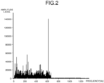
- FIG. 3 is a diagram illustrating one example of a frequency analysis result of vibration data of the first embodiment of the present disclosure.
- a frequency component of 618 Hz has the maximum amplitude level.
- the vibration frequency when there is nothing abnormal in the conveyance motor is 666 Hz
- the vibration frequency when something abnormal has occurred in the conveyance motor is 633 Hz or 599 Hz.
- the determining unit 52 determines, setting a reference value to, for example, 640 Hz, that there is a failure in the field repair unit when the frequency of a frequency component having the maximum amplitude level in a frequency analysis result (hereinafter, referred to as "maximum level frequency" in some cases) is lower than the reference value of 640 Hz.
- maximum frequency level is equal to or higher than the reference value of 640 Hz
- the determining unit 52 determines that there is no failure occurring in the field repair unit. Therefore, for example, when the maximum level frequency is 618 Hz as shown in FIG. 3, the determining unit 52 determines that a failure has occurred in the field repair unit.
- the determining unit 52 When it is determined that a failure has occurred in a field repair unit, the determining unit 52 notifies of occurrence of a failure in the field repair unit and information enabling to uniquely identify the field repair unit in which the failure has occurred to the outside of the bill handling apparatus 1.
- the determining unit 52 acquires vibration data regularly (for example, once a day) from the vibration detection sensor 51 per field repair unit, and analyzes changes of the vibration data collected over multiple days (for example, 30 days), and thereby predicts the time when a failure occurs in the field repair unit (hereinafter, "failure occurrence time" in some cases). Moreover, the determining unit 52 notifies of the predicted failure occurrence time to the outside of the bill handling apparatus 1. This enables to replace a field repair unit in a preventive manner before a failure occurs in the field repair unit.
- the determining unit 52 may predict the failure occurrence time based on a change of the maximum level frequency across multiple days.
- Collection and analysis of the vibration data, prediction of the failure occurrence time, and notification of the failure occurrence time may be performed by a server or the like that is connected to the bill handling apparatus 1 through a network, in place of the determining unit 52.
- the bill handling apparatus of the present disclosure includes field repair units (the money receiving/paying unit 3, the first storage unit 4, the second storage unit 6, the storage cassettes 7a to 7d, the rejecting unit 8 of the embodiments), a sensor (the vibration detection sensors 51A to 51H of the embodiments), and a determining unit (the determining unit 52 of the embodiments).
- the sensor detects vibrations of a field repair unit.
- the determining unit determines whether there is a failure in the field repair unit based on the vibrations detected by the sensor.
- the determining unit subjects the vibrations detected by the sensor to frequency analysis, and determines that a failure has occurred in a field repair unit when the frequency of a frequency component having the maximum amplitude level in an analysis result of the frequency analysis is lower than a reference value.
Landscapes
- Physics & Mathematics (AREA)
- General Physics & Mathematics (AREA)
- Controlling Sheets Or Webs (AREA)
- Inspection Of Paper Currency And Valuable Securities (AREA)
Abstract
Description
- The present invention relates to a bill handling apparatus and a failure determination method.
- Some kinds of bill handling apparatuses, such as automatic teller machine, include a field repair unit that is individually replaceable. Examples of the field repair unit include a money receiving/paying unit that performs reception and payment of bills, a storage unit that temporarily stores bills, storage cassettes that store bills by denomination, and the like.
- Patent Literature 1:
JP-A-2011-008336 - When a failure occurs in a field repair unit, use of the bill handling apparatus becomes difficult.
- Accordingly, in the present application, a technique enabling to detect a failure of a field repair unit is proposed.
- A bill handling apparatus in the present application includes a field repair unit, a sensor and a determining unit. The sensor detects a vibration of the field repair unit. The determining unit determines whether there is a failure in the field repair unit based on the vibration.
- According to the disclosed technique, a failure of a field repair unit can be detected.
-
-
FIG. 1 is a diagram illustrating a configuration example of a first bill handling apparatus according to a first embodiment of the present disclosure. -
FIG. 2 is a diagram illustrating an example of a frequency analysis result of vibration data of the first embodiment of the present disclosure. - Hereinafter, embodiments of the present disclosure will be explained based on the drawings. Throughout the embodiments, like reference symbols are assigned to like components.
-
FIG. 1 is a diagram illustrating a configuration example of a bill handling apparatus of a first embodiment of the present disclosure. - As illustrated in
FIG. 1 , abill handling apparatus 1 includes a money receiving/paying unit 3 that receives and pays abill 2, afirst storage unit 4 that temporarily stores the bill put by the money receiving/paying unit 3, adiscriminating unit 5 that discriminates the bill transferred from thefirst storage unit 4, and asecond storage unit 6 that temporarily stores thebill 2 transferred from thediscriminating unit 5. Moreover, thebill handling apparatus 1 includes a returningunit 7 that stores thebill 2 transferred from thediscriminating unit 5, and that returns thebill 2 by ejecting therefrom, and a rejectingunit 8 that stores thebill 2 that has abnormal thickness or length, thebill 2 that is damaged, and the like. - The
bill 2 that is put in from the money receiving/paying unit 3 is stored in thefirst storage unit 4, and then discriminated by thediscriminating unit 5. Thebill 2 from which something abnormal is detected is transferred from thediscriminating unit 5 to the rejectingunit 8 to be stored therein. On the other hand, thebill 2 from which nothing abnormal is detected by thediscriminating unit 5 is stored in thesecond storage unit 6. - When return processing is performed for the
bill 2 that has put in from the money receiving/paying unit 3, thebill 2 stored in thesecond storage unit 6 is transferred to the money receiving/paying unit 3, and is returned from the money receiving/paying unit 3. On the other hand, when money receiving processing is performed for thebill 2 that has put in from the money receiving/paying unit 3, the bill stored in thesecond storage unit 6 is transferred to thefirst storage unit 4, and is transferred from thefirst storage unit 4 to thediscriminating unit 5, and is then transferred from thediscriminating unit 5 to the returningunit 7, and is stored instorage cassettes unit 7 by denomination. - Furthermore, when the
bill 2 stored in the returningunit 7 is dispensed, thebill 2 stored in the returningunit 7 is transferred from the returningunit 7 to thediscriminating unit 5, and is then transferred from thediscriminating unit 5 to thesecond storage unit 6 to be stored in thesecond storage unit 6. Thebill 2 that is stored in thesecond storage unit 6 is transferred to the money receiving/paying unit 3, and is dispensed from the money receiving/paying unit 3. - Each of the money receiving/paying unit 3, the
first storage unit 4, thesecond storage unit 6, thestorage cassettes 7a to 7d, and the rejectingunit 8 is one example of the field repair unit individually replaceable. Each of the money receiving/paying unit 3, thefirst storage unit 4, thesecond storage unit 6, thestorage cassettes 7a to 7d, and the rejectingunit 8 includes a conveyance roller to convey thebill 2, and a conveyance motor to drive the conveyance roller. Because each of the money receiving/paying unit 3, thefirst storage unit 4, thesecond storage unit 6, thestorage cassettes 7a to 7d, and the rejectingunit 8 has the conveyance motor, vibrations occur when the conveyance motor rotates. - To the money receiving/paying unit 3, a
vibration detection sensor 51A is mounted, to thefirst storage unit 4, avibration detection sensor 51B is mounted, to thesecond storage unit 6, avibration detection sensor 51C is mounted, and to the rejectingunit 8, avibration detection sensor 51H is mounted. Moreover, to thestorage cassette 7a, avibration detection sensor 51D is mounted, to thestorage cassette 7b, avibration detection sensor 51E is mounted, to thestorage cassette 7c, avibration detection sensor 51F is mounted, and to thestorage cassette 7d, avibration detection sensor 51G is mounted. - Furthermore, the
bill handling apparatus 1 includes a determiningunit 52. - Hereinafter, the money receiving/paying unit 3, the
first storage unit 4, thesecond storage unit 6, thestorage cassettes 7a to 7d, and the rejectingunit 8 can be collectively referred to as "field repair unit". Moreover, hereinafter, thevibration detection sensors 51A to 51H can be collectively referred to as "vibration detection sensor 51". - One example of a vibration detection sensor 51 is an acceleration sensor. The determining
unit 52 is implemented by, for example, digital signal processor (DSP), a field programmable gate array (FPGA), or the like as hardware. - The respective vibration detection sensors 51 mounted on the respective field repair units detect vibrations of the respective field repair units continuously over time, and outputs chronological data indicating values of vibrations (hereinafter, referred to as "vibration data" in some cases) to the determining
unit 52. Thevibration detection sensor 51A outputs vibration data of the money receiving/paying unit 3 to the determiningunit 52, thevibration sensor 51B outputs vibration data of thefirst storage unit 4 to the determiningunit 52, thevibration detection sensor 51C outputs vibration data of thesecond storage unit 6 to the determiningunit 52, and thevibration detection sensor 51H outputs vibration data of the rejectingunit 8 to the determiningunit 52. Moreover, thevibration detection sensor 51D outputs vibration data of thestorage cassette 7a to the determiningunit 52, thevibration detection sensor 51E outputs vibration data of thestorage cassette 7b to the determiningunit 52, thevibration detection sensor 51F outputs vibration data of thestorage cassette 7c to the determiningunit 52, and thevibration detection sensor 51G outputs vibration data of thestorage cassette 7d to the determiningunit 52. - The determining
unit 52 determines whether there is a failure in a field repair unit for each of the field repair units based on vibrations detected by the vibration detection sensor 51. - The frequency of a vibration (hereinafter, referred to as "vibration frequency" in some cases) of the field repair unit varies according to a condition of the conveyance motor of the field repair unit. For example, when the rotation speed in a state in which a normal conveyance motor having 20 teeth continuously rotates at a uniform speed is 2000 rpm, and because the frequency corresponding to 2000 rpm is 33.3 Hz, the vibration frequency is 33.3×20=666 Hz. Therefore, the vibration frequency when an abnormal gear having 19 teeth with one tooth chipped out of 20 teeth rotates at 2000 rpm is 33.3×19=633 Hz. Furthermore, the vibration frequency when an abnormal gear having 18 teeth with two teeth chipped out of 20 teeth rotates at 2000 rpm is 33.3×18=599 Hz.
- The determining
unit 52 subjects the vibration data to frequency analysis. The determiningunit 52 performs the frequency analysis of vibration data, for example, by using fast Fourier transform (FFT). FIG. 3 is a diagram illustrating one example of a frequency analysis result of vibration data of the first embodiment of the present disclosure. In the frequency analysis result shown in FIG. 3, a frequency component of 618 Hz has the maximum amplitude level. On the other hand, as described above, the vibration frequency when there is nothing abnormal in the conveyance motor is 666 Hz, and the vibration frequency when something abnormal has occurred in the conveyance motor is 633 Hz or 599 Hz. - Accordingly, the determining
unit 52 determines, setting a reference value to, for example, 640 Hz, that there is a failure in the field repair unit when the frequency of a frequency component having the maximum amplitude level in a frequency analysis result (hereinafter, referred to as "maximum level frequency" in some cases) is lower than the reference value of 640 Hz. On the other hand, when the maximum frequency level is equal to or higher than the reference value of 640 Hz, the determiningunit 52 determines that there is no failure occurring in the field repair unit. Therefore, for example, when the maximum level frequency is 618 Hz as shown in FIG. 3, the determiningunit 52 determines that a failure has occurred in the field repair unit. - When it is determined that a failure has occurred in a field repair unit, the determining
unit 52 notifies of occurrence of a failure in the field repair unit and information enabling to uniquely identify the field repair unit in which the failure has occurred to the outside of thebill handling apparatus 1. - As above, the first embodiment has been explained.
- The determining
unit 52 acquires vibration data regularly (for example, once a day) from the vibration detection sensor 51 per field repair unit, and analyzes changes of the vibration data collected over multiple days (for example, 30 days), and thereby predicts the time when a failure occurs in the field repair unit (hereinafter, "failure occurrence time" in some cases). Moreover, the determiningunit 52 notifies of the predicted failure occurrence time to the outside of thebill handling apparatus 1. This enables to replace a field repair unit in a preventive manner before a failure occurs in the field repair unit. - For example, the determining
unit 52 may predict the failure occurrence time based on a change of the maximum level frequency across multiple days. - Collection and analysis of the vibration data, prediction of the failure occurrence time, and notification of the failure occurrence time may be performed by a server or the like that is connected to the
bill handling apparatus 1 through a network, in place of the determiningunit 52. - As above, the second embodiment has been explained.
- As described, the bill handling apparatus of the present disclosure (the
bill handling apparatus 1 of the embodiments) includes field repair units (the money receiving/paying unit 3, thefirst storage unit 4, thesecond storage unit 6, thestorage cassettes 7a to 7d, the rejectingunit 8 of the embodiments), a sensor (thevibration detection sensors 51A to 51H of the embodiments), and a determining unit (the determiningunit 52 of the embodiments). The sensor detects vibrations of a field repair unit. The determining unit determines whether there is a failure in the field repair unit based on the vibrations detected by the sensor. - Thus, a failure of the field repair unit can be detected.
- Moreover, the determining unit subjects the vibrations detected by the sensor to frequency analysis, and determines that a failure has occurred in a field repair unit when the frequency of a frequency component having the maximum amplitude level in an analysis result of the frequency analysis is lower than a reference value.
- Thus, determination whether there is a failure occurring in a field repair unit can be performed accurately.
-
- 1 BILL HANDLING APPARATUS
-
51A TO 51H VIBRATION DETECTION SENSOR - 52 DETERMINING UNIT
Claims (3)
- A bill handling apparatus comprising:a field repair unit;a sensor that detects a vibration of the field repair unit; anda determining unit that determines whether there is a failure in the field repair unit based on the vibration.
- The bill handling apparatus according to claim 1, wherein
the determining unit subject the vibration to frequency analysis, and determines that a failure has occurred in the field repair unit when a frequency of a frequency component having a maximum amplitude level in an analysis result of the frequency analysis is lower than a reference value. - A failure determination method for a bill handling unit that has a field repair unit, the method comprising:detecting a vibration of the field repair unit; anddetermining whether there is a failure in the field repair unit based on the vibration.
Applications Claiming Priority (1)
| Application Number | Priority Date | Filing Date | Title |
|---|---|---|---|
| PCT/JP2021/011929 WO2022201292A1 (en) | 2021-03-23 | 2021-03-23 | Bill processing device and failure determination method |
Publications (2)
| Publication Number | Publication Date |
|---|---|
| EP4318420A1 true EP4318420A1 (en) | 2024-02-07 |
| EP4318420A4 EP4318420A4 (en) | 2024-05-15 |
Family
ID=83396453
Family Applications (1)
| Application Number | Title | Priority Date | Filing Date |
|---|---|---|---|
| EP21932902.6A Pending EP4318420A4 (en) | 2021-03-23 | 2021-03-23 | INVOICE PROCESSING DEVICE AND DEFAULT DETERMINATION METHOD |
Country Status (5)
| Country | Link |
|---|---|
| US (1) | US12562018B2 (en) |
| EP (1) | EP4318420A4 (en) |
| JP (1) | JP7461566B2 (en) |
| CN (1) | CN116888649A (en) |
| WO (1) | WO2022201292A1 (en) |
Family Cites Families (7)
| Publication number | Priority date | Publication date | Assignee | Title |
|---|---|---|---|---|
| JP2005033559A (en) * | 2003-07-14 | 2005-02-03 | Fuji Xerox Co Ltd | Failure diagnostic device |
| JP5258681B2 (en) | 2009-06-23 | 2013-08-07 | 日立オムロンターミナルソリューションズ株式会社 | Banknote handling equipment |
| WO2012048225A1 (en) * | 2010-10-08 | 2012-04-12 | Rolls-Royce Corporation | System and method for detecting fault conditions in a drivetrain using torque oscillation data |
| JP7051516B2 (en) * | 2018-03-22 | 2022-04-11 | 株式会社東芝 | Paper leaf processing system processing method and paper leaf processing system |
| US11486483B1 (en) * | 2019-07-08 | 2022-11-01 | Gpms International, Inc. | Condition monitoring for components of a gearbox |
| CN110599668B (en) * | 2019-08-26 | 2021-05-11 | 深圳市合众金融设备服务有限公司 | Abnormal detection method and system for number of paper money in money box, server and financial equipment |
| CN111457958A (en) * | 2020-03-10 | 2020-07-28 | 利维智能(深圳)有限公司 | Port machine equipment situation monitoring method and device, computer equipment and storage medium |
-
2021
- 2021-03-23 CN CN202180094857.2A patent/CN116888649A/en active Pending
- 2021-03-23 EP EP21932902.6A patent/EP4318420A4/en active Pending
- 2021-03-23 WO PCT/JP2021/011929 patent/WO2022201292A1/en not_active Ceased
- 2021-03-23 JP JP2023508208A patent/JP7461566B2/en active Active
-
2023
- 2023-08-22 US US18/453,848 patent/US12562018B2/en active Active
Also Published As
| Publication number | Publication date |
|---|---|
| JPWO2022201292A1 (en) | 2022-09-29 |
| CN116888649A (en) | 2023-10-13 |
| EP4318420A4 (en) | 2024-05-15 |
| WO2022201292A1 (en) | 2022-09-29 |
| US12562018B2 (en) | 2026-02-24 |
| JP7461566B2 (en) | 2024-04-03 |
| US20230394902A1 (en) | 2023-12-07 |
Similar Documents
| Publication | Publication Date | Title |
|---|---|---|
| KR920002072B1 (en) | Diagnastic system of revolution machine | |
| EP2526389A1 (en) | Apparatus for analysing the condition of a machine having a rotating part | |
| CN110599670B (en) | Abnormal detection method and system for number of paper money in money box, server and financial equipment | |
| US10508974B2 (en) | Storing analytical machine data based on change in scalar machine data indicating alert condition | |
| FR2590704A1 (en) | Method for automatic diagnosis of the operating state of an apparatus | |
| CN110910563B (en) | ATM (automatic teller machine) and cash quantity monitoring method and system for cash boxes | |
| EP4318420A1 (en) | Bill processing device and failure determination method | |
| CN107221069B (en) | method and device for detecting continuous paper money and storage medium | |
| CN110599668B (en) | Abnormal detection method and system for number of paper money in money box, server and financial equipment | |
| CN108230546B (en) | Banknote thickness abnormality detection method and device, terminal device and storage medium | |
| JP7630655B2 (en) | Deterioration determination system and deterioration determination method | |
| JP3199605B2 (en) | Metal contamination detector in banknote deposit machine | |
| WO2016199520A1 (en) | Thickness detection device and medium transaction device | |
| JPH07113901B2 (en) | Self-diagnosis device for medium transport system | |
| CN112485000A (en) | Machine fault prediction based on vibration trend information | |
| CN119948542A (en) | Paper sheet processing device, gaming machine management device using the paper sheet processing device, and method for displaying the degree of degradation of the paper sheet processing device | |
| JP2008204325A (en) | Cash processor and cash processing program | |
| CN113269926A (en) | Medium detection method and device, electronic equipment and storage medium | |
| CN115131908B (en) | Method and device for detecting magnetic equipment | |
| JP3732647B2 (en) | Automatic cash deposit / withdrawal device | |
| JP3296672B2 (en) | Media transfer interruption processing method | |
| JP5316257B2 (en) | Automatic teller machine and how to handle forgotten banknotes of automatic teller machine | |
| JP7848005B2 (en) | Paper handling apparatus and its maintenance method | |
| DK179612B1 (en) | A mechanism and a method for detecting and detaining invalid coins and a coin processing apparatus comprising such a mechanism | |
| JP4441986B2 (en) | Slot machine security equipment |
Legal Events
| Date | Code | Title | Description |
|---|---|---|---|
| STAA | Information on the status of an ep patent application or granted ep patent |
Free format text: STATUS: THE INTERNATIONAL PUBLICATION HAS BEEN MADE |
|
| PUAI | Public reference made under article 153(3) epc to a published international application that has entered the european phase |
Free format text: ORIGINAL CODE: 0009012 |
|
| STAA | Information on the status of an ep patent application or granted ep patent |
Free format text: STATUS: REQUEST FOR EXAMINATION WAS MADE |
|
| 17P | Request for examination filed |
Effective date: 20230828 |
|
| AK | Designated contracting states |
Kind code of ref document: A1 Designated state(s): AL AT BE BG CH CY CZ DE DK EE ES FI FR GB GR HR HU IE IS IT LI LT LU LV MC MK MT NL NO PL PT RO RS SE SI SK SM TR |
|
| A4 | Supplementary search report drawn up and despatched |
Effective date: 20240417 |
|
| RIC1 | Information provided on ipc code assigned before grant |
Ipc: G07D 11/40 20190101ALI20240411BHEP Ipc: G07D 11/235 20190101AFI20240411BHEP |
|
| DAV | Request for validation of the european patent (deleted) | ||
| DAX | Request for extension of the european patent (deleted) | ||
| RAP1 | Party data changed (applicant data changed or rights of an application transferred) |
Owner name: FUJITSU FRONTECH LIMITED Owner name: FUJITSU FRONTECH SYSTEMS LIMITED |