EP4318394A1 - System and method for generating training image data for supervised machine learning, and program - Google Patents
System and method for generating training image data for supervised machine learning, and program Download PDFInfo
- Publication number
- EP4318394A1 EP4318394A1 EP23187483.5A EP23187483A EP4318394A1 EP 4318394 A1 EP4318394 A1 EP 4318394A1 EP 23187483 A EP23187483 A EP 23187483A EP 4318394 A1 EP4318394 A1 EP 4318394A1
- Authority
- EP
- European Patent Office
- Prior art keywords
- defect
- image data
- inspection target
- model
- target surface
- Prior art date
- Legal status (The legal status is an assumption and is not a legal conclusion. Google has not performed a legal analysis and makes no representation as to the accuracy of the status listed.)
- Granted
Links
Images




Classifications
-
- G—PHYSICS
- G06—COMPUTING OR CALCULATING; COUNTING
- G06V—IMAGE OR VIDEO RECOGNITION OR UNDERSTANDING
- G06V10/00—Arrangements for image or video recognition or understanding
- G06V10/70—Arrangements for image or video recognition or understanding using pattern recognition or machine learning
- G06V10/764—Arrangements for image or video recognition or understanding using pattern recognition or machine learning using classification, e.g. of video objects
-
- G—PHYSICS
- G06—COMPUTING OR CALCULATING; COUNTING
- G06T—IMAGE DATA PROCESSING OR GENERATION, IN GENERAL
- G06T7/00—Image analysis
- G06T7/0002—Inspection of images, e.g. flaw detection
- G06T7/0004—Industrial image inspection
- G06T7/0008—Industrial image inspection checking presence/absence
-
- G—PHYSICS
- G06—COMPUTING OR CALCULATING; COUNTING
- G06T—IMAGE DATA PROCESSING OR GENERATION, IN GENERAL
- G06T11/00—Two-dimensional [2D] image generation
-
- G—PHYSICS
- G06—COMPUTING OR CALCULATING; COUNTING
- G06N—COMPUTING ARRANGEMENTS BASED ON SPECIFIC COMPUTATIONAL MODELS
- G06N3/00—Computing arrangements based on biological models
- G06N3/02—Neural networks
- G06N3/04—Architecture, e.g. interconnection topology
- G06N3/0464—Convolutional networks [CNN, ConvNet]
-
- G—PHYSICS
- G06—COMPUTING OR CALCULATING; COUNTING
- G06N—COMPUTING ARRANGEMENTS BASED ON SPECIFIC COMPUTATIONAL MODELS
- G06N3/00—Computing arrangements based on biological models
- G06N3/02—Neural networks
- G06N3/08—Learning methods
- G06N3/09—Supervised learning
-
- G—PHYSICS
- G06—COMPUTING OR CALCULATING; COUNTING
- G06T—IMAGE DATA PROCESSING OR GENERATION, IN GENERAL
- G06T15/00—Three-dimensional [3D] image rendering
- G06T15/06—Ray-tracing
-
- G—PHYSICS
- G06—COMPUTING OR CALCULATING; COUNTING
- G06T—IMAGE DATA PROCESSING OR GENERATION, IN GENERAL
- G06T15/00—Three-dimensional [3D] image rendering
- G06T15/50—Lighting effects
-
- G—PHYSICS
- G06—COMPUTING OR CALCULATING; COUNTING
- G06T—IMAGE DATA PROCESSING OR GENERATION, IN GENERAL
- G06T7/00—Image analysis
- G06T7/0002—Inspection of images, e.g. flaw detection
- G06T7/0004—Industrial image inspection
-
- G—PHYSICS
- G06—COMPUTING OR CALCULATING; COUNTING
- G06V—IMAGE OR VIDEO RECOGNITION OR UNDERSTANDING
- G06V10/00—Arrangements for image or video recognition or understanding
- G06V10/40—Extraction of image or video features
- G06V10/60—Extraction of image or video features relating to illumination properties, e.g. using a reflectance or lighting model
-
- G—PHYSICS
- G06—COMPUTING OR CALCULATING; COUNTING
- G06V—IMAGE OR VIDEO RECOGNITION OR UNDERSTANDING
- G06V10/00—Arrangements for image or video recognition or understanding
- G06V10/70—Arrangements for image or video recognition or understanding using pattern recognition or machine learning
- G06V10/77—Processing image or video features in feature spaces; using data integration or data reduction, e.g. principal component analysis [PCA] or independent component analysis [ICA] or self-organising maps [SOM]; Blind source separation
- G06V10/774—Generating sets of training patterns; Bootstrap methods, e.g. bagging or boosting
-
- G—PHYSICS
- G06—COMPUTING OR CALCULATING; COUNTING
- G06V—IMAGE OR VIDEO RECOGNITION OR UNDERSTANDING
- G06V10/00—Arrangements for image or video recognition or understanding
- G06V10/70—Arrangements for image or video recognition or understanding using pattern recognition or machine learning
- G06V10/82—Arrangements for image or video recognition or understanding using pattern recognition or machine learning using neural networks
-
- G—PHYSICS
- G06—COMPUTING OR CALCULATING; COUNTING
- G06V—IMAGE OR VIDEO RECOGNITION OR UNDERSTANDING
- G06V20/00—Scenes; Scene-specific elements
- G06V20/70—Labelling scene content, e.g. deriving syntactic or semantic representations
-
- G—PHYSICS
- G06—COMPUTING OR CALCULATING; COUNTING
- G06T—IMAGE DATA PROCESSING OR GENERATION, IN GENERAL
- G06T2207/00—Indexing scheme for image analysis or image enhancement
- G06T2207/20—Special algorithmic details
- G06T2207/20081—Training; Learning
-
- G—PHYSICS
- G06—COMPUTING OR CALCULATING; COUNTING
- G06T—IMAGE DATA PROCESSING OR GENERATION, IN GENERAL
- G06T2207/00—Indexing scheme for image analysis or image enhancement
- G06T2207/20—Special algorithmic details
- G06T2207/20084—Artificial neural networks [ANN]
-
- G—PHYSICS
- G06—COMPUTING OR CALCULATING; COUNTING
- G06T—IMAGE DATA PROCESSING OR GENERATION, IN GENERAL
- G06T2207/00—Indexing scheme for image analysis or image enhancement
- G06T2207/30—Subject of image; Context of image processing
- G06T2207/30108—Industrial image inspection
- G06T2207/30156—Vehicle coating
Definitions
- the present invention relates to a system and a method for generating training image data for supervised machine learning, and a program, which generate training image data for training a defect classifier to be applied to classify the type of a surface defect in visual inspection of a workpiece.
- a so-called visual inspection apparatus which uses a digital camera to capture an image of an inspection target surface of a workpiece illuminated by controlled lighting means, and processes the captured image to detect a surface defect, is used in various industrial fields.
- a digital camera to capture an image of an inspection target surface of a workpiece illuminated by controlled lighting means, and processes the captured image to detect a surface defect.
- a classifier is generated by training a supervised machine learning algorithm.
- a deep learning method called a convolutional neural network (CNN) is widely used because of its superiority in performance.
- Patent Literature 1 Japanese Unexamined Patent Application Publication No. 2021-43010 discloses the following optical condition determination system for the purpose of obtaining an optimal optical condition to be applied to visual inspection.
- the optical condition determination system includes a simulation executor that generates a surface property image and a defect image by performing an optical simulation under a plurality of optical conditions for each of a surface property model obtained by modeling a surface property of an object to be visually inspected and a defect model obtained by modeling a defect of the object.
- the optical condition determination system further includes an image synthesizer that synthesizes the surface property image and the defect image generated by the optical simulation under the same optical conditions to generate a synthesized image, and an evaluation value calculator that calculates an evaluation value indicating how easily the defect is detected in the synthesized image.
- the optical condition determination system further includes a correlation analyzer that analyzes a correlation between the optical conditions corresponding to the synthesized image and the evaluation value, and an optimum condition searcher that searches for an optical condition suitable for the visual inspection based on a result of the analysis of the correlation.
- Patent Literature 2 discloses the following method for determining arrangement of a surface defect inspection apparatus.
- the arrangement position and the optical axis direction of each of a lighting unit and an image sensing unit are set as the first and second arrangement information.
- the inspection target object is illuminated by the lighting unit based on the first arrangement information
- an image of an inspection region is captured by the image sensing unit based on the second arrangement information
- the image is obtained by numerical calculation.
- the defect is detected based on the image.
- Patent Literatures 1 and 2 are intended to obtain optical conditions optimal for visual inspection, and are not techniques for generating training image data for training a supervised machine learning algorithm. Therefore, it is not possible to solve the problems related to the acquisition of training data as described above.
- An object of the present invention is to provide a system and a method for generating training image data for supervised machine learning, and a program that are able to easily generate appropriate training image data for performing defect classification using the supervised machine learning.
- a defect model is arbitrarily selected from the defect model storage to store the defect models obtained by modeling the shapes and optical characteristics of the defects.
- An inspection target surface model is arbitrarily selected from the inspection target surface storage to store the inspection target surface models obtained by modeling the shapes and optical characteristics of the inspection target surfaces.
- the selected defect model and the selected inspection target surface model are arranged in any space in which ray tracing is performed by the ray tracing simulation software in which the lighting optical system, the imaging optical system, and the imaging sensor including the plurality of pixels are modeled.
- a plurality of light rays are traced, and illuminance in each of the pixels is calculated based on an intensity and the number of light rays entering the pixels.
- Pseudo image data is generated as the training image data based on the calculated illuminance.
- a defect shape and other characteristics for example, a shape of an inspection target surface, optical characteristics of the inspection target surface, lighting conditions, imaging conditions, and the like
- a sufficient amount of training data can be easily obtained even for a small defect that occurs at a low rate.
- the program can cause the computer to execute acquiring an arbitrarily selected defect model from the defect model storage to store the defect models obtained by modeling the shapes and optical characteristics of the defects, acquiring an arbitrarily selected inspection target surface model from the inspection target surface model storage to store the inspection target surface models obtained by modeling the shapes and optical characteristics of the inspection target surfaces, arranging the acquired defect model and the acquired inspection target surface model in any space in which ray tracing is performed by the ray tracing simulation software in which the lighting optical system, the imaging optical system, and the imaging sensor including the plurality of pixels are modeled, tracing a plurality of light rays, calculating illuminance in each of the pixels based on an intensity and number of light rays entering the pixels, and generating pseudo image data as training image data based on the calculated illuminance.
- Fig. 1 is a configuration diagram of a training image data generation system 1 according to an embodiment of the present invention.
- a case of generating training image data for training a defect classifier to be applied to classify the type of a surface defect in visual inspection of a vehicle body will be described.
- the training image data generation system 1 includes a personal computer (hereinafter, also referred to as a PC), and the PC includes, in terms of hardware, a central processing unit (CPU) 2, a random access memory (RAM) 3, an input section 4 such as a mouse or a keyboard, a display section 5 such as a liquid crystal display, a network interface (network I/F) 6 for communicating with an external device via a network, and a storage section 7 such as a hard disk or a solid state drive (SSD).
- the storage section 7 stores defect models, inspection target surface models, ray tracing simulation software, and other programs. These will be described later.
- the PC functionally includes a data generator 8.
- a function of the data generator 8 is implemented by the CPU 2 operating in accordance with a program stored in the storage section 7 and loaded into the RAM 3.
- Each of the defect models stored in the storage section 7 is obtained by modeling a shape and an optical characteristic of a defect.
- each of the defect models stored in the storage section 7 is given a label indicating a defect type of the defect model.
- FIG. 2A An example of the optical characteristics in the defect models is illustrated in Figs. 2A and 2B .
- characteristics illustrated in Figs. 2A and 2B are an example of optical characteristics of a coating defect generated when a primer layer 13, a base coat layer 14, and a clear layer 15 are sequentially formed by coating on a surface of a steel plate (coating surface) 11 in a vehicle body 10 via an electrodeposition layer 12 and a foreign matter 20 is mixed into the clear layer 15.
- the light absorptance of the foreign matter 20 is set to 100%
- the reflectance of the surface of the clear layer 15 is set to 4%
- scattering characteristics in the base coat layer 14 are set to characteristics illustrated in Fig. 2B .
- Figs. 3A to 3C Examples of the shapes of the defects in the defect models are illustrated in Figs. 3A to 3C . Differences in defect type are mainly due to differences in defect shape.
- a model illustrated in Fig. 3A is a model in which dust is mixed in a coating to form a conical surface protruding defect 31.
- a model illustrated in Fig. 3B is a model in which a pinhole is formed in a coating surface to form a conical surface recessed defect 32.
- a model illustrated in Fig. 3C is a model in which a drop of paint forms a surface protruding defect 33 having a semi-elliptical longitudinal cross section. The shape of each defect is held in an array of three-dimensional coordinates.
- Each of the inspection target surface models stored in the storage section 7 is obtained by modeling a shape of an inspection target surface that is a surface of an object to be inspected and an optical characteristic of the inspection target surface.
- FIG. 4A indicates a shape of an inspection target surface 41 of a part of a door of the vehicle body 10 illustrated in Fig. 4D
- a model illustrated in Fig. 4B indicates a shape of an inspection target surface 42 of an accent line of a door of the vehicle body 10 illustrated in Fig. 4D
- a model illustrated in Fig. 4C indicates a shape of an inspection target surface 43 of a wheel house which is a wheel housing part of the vehicle body 10 illustrated in Fig. 4D .
- the shape of each of the inspection target surfaces 41 to 43 is held in an array of three-dimensional coordinates.
- the optical characteristics of the inspection target surfaces 41 to 43 in the inspection target surface models are the reflection characteristics of the clear layer 15, the scattering characteristics of the base coat layer 14, and the like in the inspection target surfaces 41 to 43.
- the reflectance and the scattering characteristics it is desirable to provide characteristics that match the inspection target surfaces to be actually inspected.
- the defect models and the inspection target surface models are stored in the single storage section 7 incorporated in the PC constituting the training image data generation system 1.
- the defect models and the inspection target surface models may be stored in different storage sections.
- at least one of the defect models and the inspection target surface models may be stored in a storage section present outside the PC.
- the PC acquires any defect model and any inspection target surface model from the external storage section.
- the data generator 8 generates training image data, and includes a shape synthesizer 81 and an image processor 82.
- the shape synthesizer 81 synthesizes a shape of a defect model and a shape of an inspection target surface model.
- the image processor 82 performs image processing on the generated training image data.
- a specific method for generating the training image data by the data generator 8 is as follows.
- a defect model stored in the storage section 7 is arbitrarily selected.
- An inspection target surface model stored in the storage section 7 is arbitrarily selected. Then, the selected defect model and the selected inspection target surface model are arranged in any space in which ray tracing is performed by the ray tracing simulation software.
- a lighting optical system 50, an imaging optical system 60, and an imaging sensor 63 including a plurality of pixels are modeled.
- the modeling of the lighting optical system 50 is implemented by, for example, a model as illustrated in Figs. 5A and 5B .
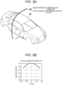
- the lighting optical system 50 including strip-shaped lighting is disposed so as to surround the vehicle body 10 in the width direction, an angular distribution of the lighting optical system 50 is set to a Lambert angular distribution, and a spatial distribution of the lighting optical system 50 is set to a distribution illustrated in Fig. 5B .
- the horizontal axis indicates the width of the lighting optical system 50.
- the modeling of the imaging optical system 60 is implemented by, for example, a model as illustrated in Fig. 6 .
- a model as illustrated in Fig. 6 .
- light 70 reflected from the inspection target surfaces 41 to 43 is focused onto the imaging sensor 63 through a lens 61 and a diaphragm 62.
- the shape of the defect and the shape of the inspection target surface are synthesized by the shape synthesizer 81.
- the shapes may be synthesized by any one of the following methods (1) to (3).
- the ray tracing simulation software is capable of geometrically optically simulating how a light ray is transmitted, refracted, and reflected to propagate, and for example, known software such as "LightTools” of Synopsys, Inc may be used. "LightTools” is a product name.
- Fig. 7 illustrates an example of arrangement of elements of a model 90 obtained by synthesizing the defect model and the inspection target surface model, the lighting optical system 50, the imaging optical system 60, and the imaging sensor 63 in a ray tracing simulation.
- illuminance in each of the pixels is calculated based on an intensity and the number of light rays reflected from the inspection target surface and incident on the pixels of the imaging sensor 63.
- pseudo image data is generated based on the calculated illuminance, and is used as training image data.
- the generated pseudo image data is output to and stored in the storage section 7 in the training image data generation system or a storage section provided outside the system in a general image format (for example, Bitmap, TIFF, or the like).
- a general image format for example, Bitmap, TIFF, or the like.
- Figs. 8A to 8C illustrate examples of the generated pseudo image data.
- imaging is continuously performed by an imaging device while moving at least one of the vehicle body or a lighting device.
- the pseudo image data illustrated in Figs. 8A to 8C is also generated while the model 90 obtained by synthesizing the defect model and the inspection target surface model is moved by a minute amount and arranged at a plurality of different positions.
- Fig. 8A illustrates the pseudo image data when the model 90 obtained by synthesizing the inspection target surface model and the defect model as a surface defect due to dust in the vicinity of the door of the vehicle body 10 is moved by a minute amount.
- Fig. 8B illustrates the pseudo image data when the model 90 obtained by synthesizing the inspection target surface model and the defect model as a surface defect due to a pinhole in the vicinity of the wheel house of the vehicle body 10 is moved by a minute amount.
- Fig. 8C illustrates pseudo image data when the model 90 obtained by synthesizing the inspection target surface model and the defect model as a surface defect due to a drop of paint in the vicinity of the accent line of the vehicle body 10 is moved by a minute amount. In each of the cases, a black dot portion in a bright zone indicates a defect.
- the luminance may slightly change or noise may occur in the image depending on the type of the surface defect, the imaging conditions, or the like. Therefore, in order to match the generated pseudo image data with the actual captured image data, image processing for changing luminance and/or adding noise may be performed on the generated pseudo image data by the image processor 82.
- a defect model is arbitrarily selected from the storage section 7 that holds defect models obtained by modeling shapes and optical characteristics of defects.
- an inspection target surface model is arbitrarily selected from the storage section 7 that holds inspection target surface models obtained by modeling shapes and optical characteristics of inspection target surfaces.
- the selected defect model and the selected inspection target surface model are arranged in any space in which ray tracing is performed by the ray tracing simulation software in which the lighting optical system, the imaging optical system 60, and the imaging sensor 63 including the plurality of pixels are modeled.
- a plurality of light rays are traced, and illuminance in each of the pixels is calculated based on an intensity and the number of light rays incident on the pixels of the imaging sensor 63.
- pseudo image data is generated as training image data. That is, since a defect model is generated by modeling a defect and training image data is generated by ray tracing, all the generated training image data is appropriate image data corresponding to the defect model, and it is not necessary to give a correct label. Therefore, appropriate training image data can be easily generated, and the cost of generating training data can be reduced.
- a defect shape and other characteristics for example, a shape of an inspection target surface, optical characteristics of the inspection target surface, lighting conditions, imaging conditions, and the like
- a sufficient amount of training data can be easily obtained even for a small defect that occurs at a low rate.
Landscapes
- Engineering & Computer Science (AREA)
- Theoretical Computer Science (AREA)
- Physics & Mathematics (AREA)
- General Physics & Mathematics (AREA)
- Software Systems (AREA)
- Evolutionary Computation (AREA)
- Multimedia (AREA)
- Computer Vision & Pattern Recognition (AREA)
- General Health & Medical Sciences (AREA)
- Health & Medical Sciences (AREA)
- Artificial Intelligence (AREA)
- Computing Systems (AREA)
- Medical Informatics (AREA)
- Databases & Information Systems (AREA)
- Computer Graphics (AREA)
- Computational Linguistics (AREA)
- Quality & Reliability (AREA)
- Life Sciences & Earth Sciences (AREA)
- Biomedical Technology (AREA)
- Biophysics (AREA)
- Data Mining & Analysis (AREA)
- Molecular Biology (AREA)
- General Engineering & Computer Science (AREA)
- Mathematical Physics (AREA)
- Investigating Materials By The Use Of Optical Means Adapted For Particular Applications (AREA)
- Image Analysis (AREA)
- Length Measuring Devices By Optical Means (AREA)
Abstract
Description
- The present invention relates to a system and a method for generating training image data for supervised machine learning, and a program, which generate training image data for training a defect classifier to be applied to classify the type of a surface defect in visual inspection of a workpiece.
- A so-called visual inspection apparatus, which uses a digital camera to capture an image of an inspection target surface of a workpiece illuminated by controlled lighting means, and processes the captured image to detect a surface defect, is used in various industrial fields. In recent years, there have been many demands for classifying the type of a defect from a captured image in order to analyze the cause of the defect or to provide information to a repair process. For this reason, development of a defect type classification function using supervised machine learning has been advanced.
- Sufficient training data (labeled image) is collected for each defect type desired to be classified, and a classifier is generated by training a supervised machine learning algorithm. In the field of image classification, a deep learning method called a convolutional neural network (CNN) is widely used because of its superiority in performance.
- In order to obtain desired defect classification performance using supervised machine learning, sufficient training data is required. In this regard, there are the following problems.
- 1. A person who has knowledge about a defect needs to give a correct label to a large amount of images, which requires a large amount of labor. Furthermore, different labels may be given to the same images depending on a person.
- 2. It takes time to collect image data for a defect that occurs at a low frequency.
- 3. Since an image changes when characteristics (e.g., shape and color) of an inspection target object differ, it is necessary to collect and learn images for respective characteristics of the inspection target object even for the same defect.
- 4. Since an image changes when an image capturing condition such as a lighting condition or a resolution of a captured image is different, it is necessary to collect and learn images for respective image capturing conditions even for the same defect.
- Patent Literature 1 (
Japanese Unexamined Patent Application Publication No. 2021-43010 - Furthermore, Patent Literature 2 (
WO2018/225406 ) discloses the following method for determining arrangement of a surface defect inspection apparatus. In this method, the arrangement position and the optical axis direction of each of a lighting unit and an image sensing unit are set as the first and second arrangement information. Based on information obtained by digitizing each of the lighting unit, the image sensing unit, and the appearance of an inspection target object including a defect, the inspection target object is illuminated by the lighting unit based on the first arrangement information, an image of an inspection region is captured by the image sensing unit based on the second arrangement information, and the image is obtained by numerical calculation. The defect is detected based on the image. - However, both of the techniques described in
Patent Literatures - An object of the present invention is to provide a system and a method for generating training image data for supervised machine learning, and a program that are able to easily generate appropriate training image data for performing defect classification using the supervised machine learning.
- The above-described object is achieved by the following means.
- (1) A system for generating training image data for supervised machine learning for training a defect classifier to be applied to visual inspection, the system including:
- a defect model storage to store defect models obtained by modeling shapes and optical characteristics of defects;
- an inspection target surface model storage to store inspection target surface models obtained by modeling shapes and optical characteristics of inspection target surfaces; and
- data generating means to:
- arrange a defect model arbitrarily selected from the defect models stored on the defect model storage and an inspection target surface model arbitrarily selected from the inspection target surface models stored on the inspection target surface model storage, in any space in which ray tracing is performed by ray tracing simulation software in which a lighting optical system, an imaging optical system, and an imaging sensor including a plurality of pixels are modeled;
- trace a plurality of light rays, calculates illuminance at each of the pixels based on an intensity and a number of light rays entering the pixels, and
- generate pseudo image data as the training image data based on the calculated illuminance.
- (2) The system for generating training image data for supervised machine learning as recited in the
aforementioned Item 1, wherein each of the defect models stored on the defect model storage is given a label indicating a defect type of the each defect model, and the pseudo image data generated by the data generating means is given the same label as the label given to the defect model used in the generation of the pseudo image data. - (3) The system for generating training image data for supervised machine learning as recited in the
aforementioned Item - (4) The system for generating training image data for supervised machine learning as recited in the
aforementioned Item - (5) The system for generating training image data for supervised machine learning as recited in the
aforementioned Item - (6) A method for generating training image data for supervised machine learning for training a defect classifier to be applied to visual inspection, the method including:
- arbitrarily selecting a defect model from defect models obtained by modeling shapes and optical characteristics of defects and stored on a defect model storage;
- arbitrarily selecting an inspection target surface model from inspection target surface models obtained by modeling shapes and optical characteristics of inspection target surfaces and stored on an inspection target surface model storage; and
- arranging the selected defect model and the selected inspection target surface model in any space in which ray tracing is performed by ray tracing simulation software in which a lighting optical system, an imaging optical system, and an imaging sensor including a plurality of pixels are modeled, tracing a plurality of light rays, calculating illuminance at each of the pixels based on an intensity and a number of light rays entering the pixels, and generating pseudo image data as the training image data based on the calculated illuminance.
- (7) The method for generating training image data for supervised machine learning as recited in the
aforementioned Item 6, wherein each of the defect models stored on the defect model storage is given a label indicating a defect type of the each defect model, and the generated pseudo image data is given the same label as the label given to the defect model used in the generation of the pseudo image data. - (8) The method for training image data for supervised machine learning as recited in the
aforementioned Item - (9) The method for generating training image data for supervised machine learning as recited in the
aforementioned Item - (10) The method for generating training image data for supervised machine learning as recited in the
aforementioned Item - (11) A program for causing a computer to execute generating training image data for supervised machine learning for training a defect classifier to be applied to visual inspection, the program causing the computer to execute:
- arbitrarily selecting a defect model from defect models obtained by modeling shapes and optical characteristics of defects and stored on a defect model storage;
- arbitrarily selecting an inspection target surface model from inspection target surface models obtained by modeling shapes and optical characteristics of inspection target surfaces and stored on an inspection target surface model storage; and
- arranging the selected defect model and the selected inspection target surface model in any space in which ray tracing is performed by ray tracing simulation software in which a lighting optical system, an imaging optical system, and an imaging sensor including a plurality of pixels are modeled, tracing a plurality of light rays, calculating illuminance at each of the pixels based on an intensity and a number of light rays entering the pixels, and generating pseudo image data as the training image data based on the calculated illuminance.
- (12) The program as recited in the
aforementioned Item 11, wherein each of the defect models stored on the defect model storage is given a label indicating a defect type of the each defect models, and the program causes the computer to execute giving the generated pseudo image data the same label as the label given to the defect model used in the generation of the pseudo image data. - (13) The program as recited in the
aforementioned Item - (14) The program as recited in the
aforementioned Item - (15) The program as recited in the
aforementioned Item - According to the system and the method for generating training image data for supervised machine learning according to the present invention, a defect model is arbitrarily selected from the defect model storage to store the defect models obtained by modeling the shapes and optical characteristics of the defects. An inspection target surface model is arbitrarily selected from the inspection target surface storage to store the inspection target surface models obtained by modeling the shapes and optical characteristics of the inspection target surfaces. The selected defect model and the selected inspection target surface model are arranged in any space in which ray tracing is performed by the ray tracing simulation software in which the lighting optical system, the imaging optical system, and the imaging sensor including the plurality of pixels are modeled. Then, a plurality of light rays are traced, and illuminance in each of the pixels is calculated based on an intensity and the number of light rays entering the pixels. Pseudo image data is generated as the training image data based on the calculated illuminance.
- That is, since a defect model is generated by modeling a defect and training image data is generated by ray tracing, all the generated training image data is appropriate image data corresponding to the defect model, and it is not necessary to give a correct label. Therefore, appropriate training image data can be easily generated, and the cost of generating training data can be reduced.
- Furthermore, since a synthesis of a defect shape and other characteristics (for example, a shape of an inspection target surface, optical characteristics of the inspection target surface, lighting conditions, imaging conditions, and the like) can be freely modeled, a sufficient amount of training data can be easily obtained even for a small defect that occurs at a low rate.
- According to the program according to the present invention, the program can cause the computer to execute acquiring an arbitrarily selected defect model from the defect model storage to store the defect models obtained by modeling the shapes and optical characteristics of the defects, acquiring an arbitrarily selected inspection target surface model from the inspection target surface model storage to store the inspection target surface models obtained by modeling the shapes and optical characteristics of the inspection target surfaces, arranging the acquired defect model and the acquired inspection target surface model in any space in which ray tracing is performed by the ray tracing simulation software in which the lighting optical system, the imaging optical system, and the imaging sensor including the plurality of pixels are modeled, tracing a plurality of light rays, calculating illuminance in each of the pixels based on an intensity and number of light rays entering the pixels, and generating pseudo image data as training image data based on the calculated illuminance.
-
-
Fig. 1 is a block diagram illustrating a configuration of a training image data generation system according to an embodiment of the present invention; -
Figs. 2A and 2B are diagrams for explaining an example of optical characteristics in a defect model; -
Figs. 3A to 3C are diagrams illustrating examples of a shape of a defect in a defect model; -
Figs. 4A to 4C are diagrams illustrating examples of a shape of an inspection target surface in an inspection target surface model; -
Figs. 5A and 5B are diagrams for explaining modeling of a lighting optical system; -
Fig. 6 is a diagram for explaining modeling of an imaging optical system; -
Fig. 7 is a diagram illustrating an example of arrangement of elements of a defect model and an inspection target surface model, a lighting optical system including lighting, an imaging optical system, and an imaging sensor in a ray tracing simulation; -
Fig. 8A is a diagram illustrating pseudo image data when a defect model and an inspection target surface model as a surface defect due to dust in the vicinity of a door of a vehicle body are moved by a minute amount;Fig. 8B is a diagram illustrating pseudo image data when a defect model and an inspection target surface model as a surface defect due to a pinhole in the vicinity of a wheel house of the vehicle body are moved by a minute amount; andFig. 8C is a diagram illustrating pseudo image data when a defect model and an inspection target surface model as a surface defect due to a drop of paint in the vicinity of an accent line of the vehicle body are moved by a minute amount. - Hereinafter, embodiments of the present invention will be described with reference to the drawings.
-
Fig. 1 is a configuration diagram of a training imagedata generation system 1 according to an embodiment of the present invention. In the present embodiment, a case of generating training image data for training a defect classifier to be applied to classify the type of a surface defect in visual inspection of a vehicle body will be described. - The training image
data generation system 1 includes a personal computer (hereinafter, also referred to as a PC), and the PC includes, in terms of hardware, a central processing unit (CPU) 2, a random access memory (RAM) 3, aninput section 4 such as a mouse or a keyboard, adisplay section 5 such as a liquid crystal display, a network interface (network I/F) 6 for communicating with an external device via a network, and astorage section 7 such as a hard disk or a solid state drive (SSD). Thestorage section 7 stores defect models, inspection target surface models, ray tracing simulation software, and other programs. These will be described later. - Meanwhile, the PC functionally includes a
data generator 8. A function of thedata generator 8 is implemented by theCPU 2 operating in accordance with a program stored in thestorage section 7 and loaded into theRAM 3. - Each of the defect models stored in the
storage section 7 is obtained by modeling a shape and an optical characteristic of a defect. Preferably, each of the defect models stored in thestorage section 7 is given a label indicating a defect type of the defect model. - An example of the optical characteristics in the defect models is illustrated in
Figs. 2A and 2B . As illustrated inFig. 2A , characteristics illustrated inFigs. 2A and 2B are an example of optical characteristics of a coating defect generated when aprimer layer 13, abase coat layer 14, and aclear layer 15 are sequentially formed by coating on a surface of a steel plate (coating surface) 11 in avehicle body 10 via anelectrodeposition layer 12 and aforeign matter 20 is mixed into theclear layer 15. The light absorptance of theforeign matter 20 is set to 100%, the reflectance of the surface of theclear layer 15 is set to 4%, and scattering characteristics in thebase coat layer 14 are set to characteristics illustrated inFig. 2B . However, for the reflectance, the absorptance, and the scattering characteristics, it is desirable to provide characteristics that match an inspection target surface that is actually inspected. - Examples of the shapes of the defects in the defect models are illustrated in
Figs. 3A to 3C . Differences in defect type are mainly due to differences in defect shape. - A model illustrated in
Fig. 3A is a model in which dust is mixed in a coating to form a conicalsurface protruding defect 31. A model illustrated inFig. 3B is a model in which a pinhole is formed in a coating surface to form a conical surface recesseddefect 32. A model illustrated inFig. 3C is a model in which a drop of paint forms asurface protruding defect 33 having a semi-elliptical longitudinal cross section. The shape of each defect is held in an array of three-dimensional coordinates. - Each of the inspection target surface models stored in the
storage section 7 is obtained by modeling a shape of an inspection target surface that is a surface of an object to be inspected and an optical characteristic of the inspection target surface. - Examples of the shapes of the inspection target surfaces in the inspection target surface models are illustrated in, for example,
Figs. 4A to 4C . A model illustrated inFig. 4A indicates a shape of aninspection target surface 41 of a part of a door of thevehicle body 10 illustrated inFig. 4D , a model illustrated inFig. 4B indicates a shape of aninspection target surface 42 of an accent line of a door of thevehicle body 10 illustrated inFig. 4D , and a model illustrated inFig. 4C indicates a shape of aninspection target surface 43 of a wheel house which is a wheel housing part of thevehicle body 10 illustrated inFig. 4D . The shape of each of the inspection target surfaces 41 to 43 is held in an array of three-dimensional coordinates. - As illustrated in
Fig. 2A , the optical characteristics of the inspection target surfaces 41 to 43 in the inspection target surface models are the reflection characteristics of theclear layer 15, the scattering characteristics of thebase coat layer 14, and the like in the inspection target surfaces 41 to 43. For the reflectance and the scattering characteristics, it is desirable to provide characteristics that match the inspection target surfaces to be actually inspected. - In the present embodiment, the defect models and the inspection target surface models are stored in the
single storage section 7 incorporated in the PC constituting the training imagedata generation system 1. However, the defect models and the inspection target surface models may be stored in different storage sections. Further, at least one of the defect models and the inspection target surface models may be stored in a storage section present outside the PC. When the defect models and the inspection target surface models are stored in a storage section present outside the PC, the PC acquires any defect model and any inspection target surface model from the external storage section. - The
data generator 8 generates training image data, and includes ashape synthesizer 81 and animage processor 82. Theshape synthesizer 81 synthesizes a shape of a defect model and a shape of an inspection target surface model. Theimage processor 82 performs image processing on the generated training image data. - A specific method for generating the training image data by the
data generator 8 is as follows. - That is, a defect model stored in the
storage section 7 is arbitrarily selected. An inspection target surface model stored in thestorage section 7 is arbitrarily selected. Then, the selected defect model and the selected inspection target surface model are arranged in any space in which ray tracing is performed by the ray tracing simulation software. In the ray tracing simulation software, a lightingoptical system 50, an imagingoptical system 60, and animaging sensor 63 including a plurality of pixels are modeled. - The modeling of the lighting
optical system 50 is implemented by, for example, a model as illustrated inFigs. 5A and 5B . In the example illustrated inFigs. 5A and 5B , the lightingoptical system 50 including strip-shaped lighting is disposed so as to surround thevehicle body 10 in the width direction, an angular distribution of the lightingoptical system 50 is set to a Lambert angular distribution, and a spatial distribution of the lightingoptical system 50 is set to a distribution illustrated inFig. 5B . InFig. 5B , the horizontal axis indicates the width of the lightingoptical system 50. However, it is desirable to generate a model that matches a spatial luminance distribution and an orientation distribution of a light source mounted in an inspection apparatus in which the classifier is to be installed. - The modeling of the imaging
optical system 60 is implemented by, for example, a model as illustrated inFig. 6 . In the example illustrated inFig. 6 , light 70 reflected from the inspection target surfaces 41 to 43 is focused onto theimaging sensor 63 through alens 61 and adiaphragm 62. In order to reproduce, on an image, optical aberration and a reduction in the amount of ambient light, which actually occur, it is desirable to perform the modeling in accordance with a lens or the like mounted on the inspection apparatus in which the classifier is to be installed. - To arrange the defect model and the inspection target surface model in any space, the shape of the defect and the shape of the inspection target surface are synthesized by the
shape synthesizer 81. The shapes may be synthesized by any one of the following methods (1) to (3). - (1) Each of the shape of the defect model and the shape of the inspection target surface model is held in a three-dimensional coordinate array, and the shapes are synthesized by summing the z values of points having the same (x, y).
- (2) Each of the shape of the defect model and the shape of the inspection target surface model are held in a two-dimensional matrix in which values indicate the heights, and the shapes are synthesized by summing the same matrix elements.
- (3) Each of the shape of the defect model and the shape of the inspection target surface model are held in any form (for example, the above-described three-dimensional coordinate array, the above-described two-dimensional matrix, or a polygon), and the shapes are synthesized by a Boolean operation.
- The ray tracing simulation software is capable of geometrically optically simulating how a light ray is transmitted, refracted, and reflected to propagate, and for example, known software such as "LightTools" of Synopsys, Inc may be used. "LightTools" is a product name.
-
Fig. 7 illustrates an example of arrangement of elements of amodel 90 obtained by synthesizing the defect model and the inspection target surface model, the lightingoptical system 50, the imagingoptical system 60, and theimaging sensor 63 in a ray tracing simulation. - In a state where the elements are arranged as described above, illuminance in each of the pixels is calculated based on an intensity and the number of light rays reflected from the inspection target surface and incident on the pixels of the
imaging sensor 63. Then, pseudo image data is generated based on the calculated illuminance, and is used as training image data. - The generated pseudo image data is output to and stored in the
storage section 7 in the training image data generation system or a storage section provided outside the system in a general image format (for example, Bitmap, TIFF, or the like). When a label indicating a defect type is given to the defect model, it is desirable that the same label as the defect type of the used defect model be given to the generated pseudo image data and the generated pseudo image data be stored from the viewpoint of easy management of the generated pseudo image data. -
Figs. 8A to 8C illustrate examples of the generated pseudo image data. In the visual inspection of the vehicle body, imaging is continuously performed by an imaging device while moving at least one of the vehicle body or a lighting device. For this reason, the pseudo image data illustrated inFigs. 8A to 8C is also generated while themodel 90 obtained by synthesizing the defect model and the inspection target surface model is moved by a minute amount and arranged at a plurality of different positions. - Specifically,
Fig. 8A illustrates the pseudo image data when themodel 90 obtained by synthesizing the inspection target surface model and the defect model as a surface defect due to dust in the vicinity of the door of thevehicle body 10 is moved by a minute amount.Fig. 8B illustrates the pseudo image data when themodel 90 obtained by synthesizing the inspection target surface model and the defect model as a surface defect due to a pinhole in the vicinity of the wheel house of thevehicle body 10 is moved by a minute amount.Fig. 8C illustrates pseudo image data when themodel 90 obtained by synthesizing the inspection target surface model and the defect model as a surface defect due to a drop of paint in the vicinity of the accent line of thevehicle body 10 is moved by a minute amount. In each of the cases, a black dot portion in a bright zone indicates a defect. - In the captured image data of the actual surface defect, the luminance may slightly change or noise may occur in the image depending on the type of the surface defect, the imaging conditions, or the like. Therefore, in order to match the generated pseudo image data with the actual captured image data, image processing for changing luminance and/or adding noise may be performed on the generated pseudo image data by the
image processor 82. - An example of a workflow of classifier installation using the training image
data generation system 1 according to the present embodiment will be described below. - [1] Information of defects generated in a mass production site is acquired in advance by using a three-dimensional shape measurement device or the like, and a plurality of defect models are prepared. An example of the three-dimensional shape measurement device that can be used on site is GelSight Mobile manufactured by GelSight, Inc. In addition, a variation distribution of shapes and characteristics may be predicted from the plurality of defect models, and the number of defect models may be increased using random numbers.
- [2] Information of a workpiece to be inspected by the inspection apparatus in which the classifier is installed is acquired, and a plurality of inspection target surface models are prepared. For example, in the case of a coating defect inspection apparatus for a vehicle body, computer-aided design (CAD) data can be provided in advance by a user of the inspection apparatus, and a surface of the CAD data can be cut out for each measurement range to generate a distribution of shapes of inspection target surfaces.
- [3] The lighting
optical system 50, the imagingoptical system 60, and theimaging sensor 63 of the inspection apparatus are arranged on the ray tracing simulation software. - [4] The defect model and the inspection target surface model are arbitrarily synthesized, and the synthesized
model 90 is arranged on the ray tracing simulation software. In a case where the defect model and the inspection target surface model are synthesized, the synthesizing may be performed in accordance with a predetermined probability distribution corresponding to the actual occurrence frequency. For example, in the case of a vehicle body coating defect, it is conceivable to control the probability of a synthesis with an inspection target surface model for each of the type of defect that is likely to occur on a vehicle body side surface and the type of defect that is likely to occur on a vehicle body upper surface. - [5] Ray tracing is performed by the ray tracing simulation software, and the luminance value of each pixel is calculated using the intensity and number of light rays that have reached each pixel of the
imaging sensor 63, converted into an image format, and output to and stored in thestorage section 7 of the PC or an external storage section. - [6] The
model 90 obtained by synthesizing the defect model and the inspection target surface shape model is moved by a minute amount, ray tracing is performed again, and an image file is output. The minute amount is determined in accordance with an imaging frame rate in the actual inspection apparatus and moving speeds of an inspection target object and image sensing means. The ray tracing for this movement is repeated a predetermined number of times to generate an image set in which a plurality of images are set. - [7] Through the above processes, a plurality of image sets (usually, several hundred or more image sets) are generated for each defect type to be classified, and a learning model for supervised machine learning is trained. In this case, it is desirable to classify the image sets into an image set for training and an image set for evaluation and check classification performance using the image set for evaluation before installing the learning model in the inspection apparatus.
- As described above, according to the training image
data generation system 1 according to the present embodiment, a defect model is arbitrarily selected from thestorage section 7 that holds defect models obtained by modeling shapes and optical characteristics of defects. In addition, an inspection target surface model is arbitrarily selected from thestorage section 7 that holds inspection target surface models obtained by modeling shapes and optical characteristics of inspection target surfaces. The selected defect model and the selected inspection target surface model are arranged in any space in which ray tracing is performed by the ray tracing simulation software in which the lighting optical system, the imagingoptical system 60, and theimaging sensor 63 including the plurality of pixels are modeled. Then, a plurality of light rays are traced, and illuminance in each of the pixels is calculated based on an intensity and the number of light rays incident on the pixels of theimaging sensor 63. Based on the calculated illuminance, pseudo image data is generated as training image data. That is, since a defect model is generated by modeling a defect and training image data is generated by ray tracing, all the generated training image data is appropriate image data corresponding to the defect model, and it is not necessary to give a correct label. Therefore, appropriate training image data can be easily generated, and the cost of generating training data can be reduced. - Furthermore, since a synthesis of a defect shape and other characteristics (for example, a shape of an inspection target surface, optical characteristics of the inspection target surface, lighting conditions, imaging conditions, and the like) can be freely modeled, a sufficient amount of training data can be easily obtained even for a small defect that occurs at a low rate.
Claims (15)
- A system (1) for generating training image data for supervised machine learning for training a defect classifier to be applied to visual inspection, the system comprising:a defect model storage (7) to store defect models obtained by modeling shapes and optical characteristics of defects;an inspection target surface model storage (7) to store inspection target surface models obtained by modeling shapes and optical characteristics of inspection target surfaces; anddata generating means (8) to:arrange a defect model arbitrarily selected from the defect models stored on the defect model storage (7) and an inspection target surface model arbitrarily selected from the inspection target surface models stored on the inspection target surface model storage (7), in any space in which ray tracing is performed by ray tracing simulation software in which a lighting optical system, an imaging optical system (60), and an imaging sensor (63) including a plurality of pixels are modeled;trace a plurality of light rays, calculates illuminance at each of the pixels based on an intensity and a number of light rays entering the pixels, andgenerate pseudo image data as the training image data based on the calculated illuminance.
- The system for generating training image data for supervised machine learning according to claim 1, wherein each of the defect models stored on the defect model storage is given a label indicating a defect type of the each defect model, and the pseudo image data generated by the data generating means (8) is given the same label as the label given to the defect model used in the generation of the pseudo image data.
- The system for generating training image data for supervised machine learning according to claim 1 or 2, wherein the data generating means (8) arranges the defect model and the inspection target surface model at a plurality of different positions on the ray tracing simulation software and generates the pseudo image data.
- The system for generating training image data for supervised machine learning according to claim 1 or 2, wherein the data generating means (8) has a function of either or both changing lightness and adding noise by performing image processing on the pseudo image data generated by the optical simulation.
- The system for generating training image data for supervised machine learning according to claim 1 or 2, wherein the data generating means (8) creates a combined shape of the defect model and the inspection target surface model and places the combined shape of the defect model and inspection target surface model in any space in which ray tracing is performed by the ray tracing simulation software.
- A method for generating training image data for supervised machine learning for training a defect classifier to be applied to visual inspection, the method comprising:arbitrarily selecting a defect model from defect models obtained by modeling shapes and optical characteristics of defects and stored on a defect model storage (7);arbitrarily selecting an inspection target surface model from inspection target surface models obtained by modeling shapes and optical characteristics of inspection target surfaces and stored on an inspection target surface model storage (7); andarranging the selected defect model and the selected inspection target surface model in any space in which ray tracing is performed by ray tracing simulation software in which a lighting optical system, an imaging optical system (60), and an imaging sensor (63) including a plurality of pixels are modeled, tracing a plurality of light rays, calculating illuminance at each of the pixels based on an intensity and a number of light rays entering the pixels, and generating pseudo image data as the training image data based on the calculated illuminance.
- The method for generating training image data for supervised machine learning according to claim 6, wherein each of the defect models stored on the defect model storage (7) is given a label indicating a defect type of the each defect model, and the generated pseudo image data is given the same label as the label given to the defect model used in the generation of the pseudo image data.
- The method for generating training image data for supervised machine learning according to claim 6 or 7, wherein the defect model and the inspection target surface model are arranged at a plurality of different positions on the ray tracing simulation software, and the pseudo image data is generated.
- The method for generating training image data for supervised machine learning according to claim 6 or 7, wherein either or both changing lightness and adding noise are achieved by performing image processing on the pseudo image data generated by the optical simulation.
- The method for generating training image data for supervised machine learning according to claim 6 or 7, wherein a combined shape of the defect model and the inspection target surface model is created, and the combined shape of the defect model and inspection target surface model is placed in any space in which ray tracing is performed by the ray tracing simulation software.
- A program for causing a computer (2) to execute generating training image data for supervised machine learning for training a defect classifier to be applied to visual inspection, the program causing the computer to execute:arbitrarily selecting a defect model from defect models obtained by modeling shapes and optical characteristics of defects and stored on a defect model storage (7);arbitrarily selecting an inspection target surface model from inspection target surface models obtained by modeling shapes and optical characteristics of inspection target surfaces and stored on an inspection target surface model storage (7); andarranging the selected defect model and the selected inspection target surface model in any space in which ray tracing is performed by ray tracing simulation software in which a lighting optical system, an imaging optical system (60), and an imaging sensor (63) including a plurality of pixels are modeled, tracing a plurality of light rays, calculating illuminance at each of the pixels based on an intensity and a number of light rays entering the pixels, and generating pseudo image data as the training image data based on the calculated illuminance.
- The program according to claim 11, wherein each of the defect models stored on the defect model storage (7) is given a label indicating a defect type of the each defect models, and the program causes the computer (2) to execute giving the generated pseudo image data the same label as the label given to the defect model used in the generation of the pseudo image data.
- The program according to claim 11 or 12, wherein the program causes the computer (2) to execute arranging the defect model and the inspection target surface model at a plurality of different positions on the ray tracing simulation software and generating the pseudo image data.
- The program according to claim 11 or 12, wherein the program causes the computer (2) to execute either or both changing lightness and adding noise by performing image processing on the pseudo image data generated by the optical simulation.
- The program according to claim 11 or 12, wherein the program causes the computer (2) to execute creating a combined shape of the defect model and the inspection target surface model and placing the combined shape of the defect model and inspection target surface model in any space in which ray tracing is performed by the ray tracing simulation software.
Applications Claiming Priority (1)
| Application Number | Priority Date | Filing Date | Title |
|---|---|---|---|
| JP2022121443A JP7666440B2 (en) | 2022-07-29 | 2022-07-29 | System, method and program for generating training image data for supervised machine learning |
Publications (2)
| Publication Number | Publication Date |
|---|---|
| EP4318394A1 true EP4318394A1 (en) | 2024-02-07 |
| EP4318394B1 EP4318394B1 (en) | 2026-04-08 |
Family
ID=87474103
Family Applications (1)
| Application Number | Title | Priority Date | Filing Date |
|---|---|---|---|
| EP23187483.5A Active EP4318394B1 (en) | 2022-07-29 | 2023-07-25 | System and method for generating training image data for supervised machine learning, and program |
Country Status (4)
| Country | Link |
|---|---|
| US (1) | US20240037728A1 (en) |
| EP (1) | EP4318394B1 (en) |
| JP (1) | JP7666440B2 (en) |
| CN (1) | CN117475192A (en) |
Families Citing this family (2)
| Publication number | Priority date | Publication date | Assignee | Title |
|---|---|---|---|---|
| CN112380475B (en) * | 2020-11-18 | 2024-04-05 | 北京沃东天骏信息技术有限公司 | Method and device for generating page |
| EP4582794A1 (en) * | 2024-06-04 | 2025-07-09 | Konica Minolta, Inc. | Defect inspection apparatus |
Citations (5)
| Publication number | Priority date | Publication date | Assignee | Title |
|---|---|---|---|---|
| WO2018225406A1 (en) | 2017-06-08 | 2018-12-13 | コニカミノルタ株式会社 | Method for determining configuration of surface defect inspection device, configuration determination device, configuration determination program, and recording medium |
| US20190238796A1 (en) * | 2017-05-11 | 2019-08-01 | Jacob Nathaniel Allen | Object Inspection System And Method For Inspecting An Object |
| JP2021043010A (en) | 2019-09-09 | 2021-03-18 | 株式会社日立製作所 | Optical condition determination system and optical condition determination method |
| US20220207716A1 (en) * | 2019-06-18 | 2022-06-30 | Tetra Laval Holdings & Finance S.A. | Detection of deviations in packaging containers for liquid food |
| US20220222855A1 (en) * | 2019-05-22 | 2022-07-14 | Blancco Technology Group IP Oy | System and method for determining whether a camera component is damaged |
Family Cites Families (2)
| Publication number | Priority date | Publication date | Assignee | Title |
|---|---|---|---|---|
| JP7186521B2 (en) | 2018-06-12 | 2022-12-09 | シチズンファインデバイス株式会社 | Teacher image generator for visual inspection equipment |
| JP7192720B2 (en) | 2019-09-04 | 2022-12-20 | 信越化学工業株式会社 | Photomask blank defect classification method and defect classification system, and photomask blank selection method and manufacturing method |
-
2022
- 2022-07-29 JP JP2022121443A patent/JP7666440B2/en active Active
-
2023
- 2023-07-25 CN CN202310914725.0A patent/CN117475192A/en active Pending
- 2023-07-25 EP EP23187483.5A patent/EP4318394B1/en active Active
- 2023-07-28 US US18/361,054 patent/US20240037728A1/en active Pending
Patent Citations (5)
| Publication number | Priority date | Publication date | Assignee | Title |
|---|---|---|---|---|
| US20190238796A1 (en) * | 2017-05-11 | 2019-08-01 | Jacob Nathaniel Allen | Object Inspection System And Method For Inspecting An Object |
| WO2018225406A1 (en) | 2017-06-08 | 2018-12-13 | コニカミノルタ株式会社 | Method for determining configuration of surface defect inspection device, configuration determination device, configuration determination program, and recording medium |
| US20220222855A1 (en) * | 2019-05-22 | 2022-07-14 | Blancco Technology Group IP Oy | System and method for determining whether a camera component is damaged |
| US20220207716A1 (en) * | 2019-06-18 | 2022-06-30 | Tetra Laval Holdings & Finance S.A. | Detection of deviations in packaging containers for liquid food |
| JP2021043010A (en) | 2019-09-09 | 2021-03-18 | 株式会社日立製作所 | Optical condition determination system and optical condition determination method |
Also Published As
| Publication number | Publication date |
|---|---|
| CN117475192A (en) | 2024-01-30 |
| US20240037728A1 (en) | 2024-02-01 |
| JP7666440B2 (en) | 2025-04-22 |
| JP2024018241A (en) | 2024-02-08 |
| EP4318394B1 (en) | 2026-04-08 |
Similar Documents
| Publication | Publication Date | Title |
|---|---|---|
| US11435297B2 (en) | Image capture method and image capture device | |
| US11310467B2 (en) | Object inspection system and method for inspecting an object | |
| Chang et al. | A lightweight appearance quality assessment system based on parallel deep learning for painted car body | |
| EP4318394B1 (en) | System and method for generating training image data for supervised machine learning, and program | |
| CN118565975B (en) | Method and system for testing performance of concrete material in high-temperature environment | |
| CN117541483B (en) | Structural performance evaluation method and system for diffusion plate | |
| CN120369618A (en) | Intelligent quality detection system based on machine vision | |
| CN121068763B (en) | Titanium alloy surface crack defect detection system based on deep learning | |
| WO2018225406A1 (en) | Method for determining configuration of surface defect inspection device, configuration determination device, configuration determination program, and recording medium | |
| CN118154562A (en) | A metal surface online defect detection system based on YOLO7 deep learning | |
| CN119904423B (en) | Method for detecting surface of automobile part based on large model | |
| JP2021154935A (en) | Vehicle simulation system, vehicle simulation method and computer program | |
| Liu et al. | Efficient optical measurement of welding studs with normal maps and convolutional neural network | |
| Ramesh et al. | Enhancing manufacturing process accuracy: A multidisciplinary approach integrating computer vision, machine learning, and control systems | |
| CN120951053B (en) | Foreign matter layering detection method, system and electronic equipment | |
| Li et al. | Full-field displacement measurements of structural vibrations using a novel two-stage neural network | |
| CN119559167B (en) | A bridge structure detection method and system based on 3D Gaussian scattering | |
| CN120533685A (en) | Robotic arm grasping method and system based on image processing | |
| CN120598891A (en) | Photovoltaic defect identification method, system and electronic equipment based on drone | |
| CN120510123A (en) | Product design optimization system and method based on image model | |
| Karaklas et al. | Empowering Precision-Guided Automotive Assembly Operations: A Flexible Robot Vision Framework | |
| Dihoru et al. | A computer vision approach for dynamic tracking of components in a nuclear reactor core model | |
| Zhou | Principal component analysis based image fusion routine with application to stamping split detection | |
| Luo et al. | Quality detection model for automotive dashboard based on an enhanced visual model | |
| CN119810105B (en) | Automated intelligent printing quality detection method and system |
Legal Events
| Date | Code | Title | Description |
|---|---|---|---|
| PUAI | Public reference made under article 153(3) epc to a published international application that has entered the european phase |
Free format text: ORIGINAL CODE: 0009012 |
|
| STAA | Information on the status of an ep patent application or granted ep patent |
Free format text: STATUS: THE APPLICATION HAS BEEN PUBLISHED |
|
| AK | Designated contracting states |
Kind code of ref document: A1 Designated state(s): AL AT BE BG CH CY CZ DE DK EE ES FI FR GB GR HR HU IE IS IT LI LT LU LV MC ME MK MT NL NO PL PT RO RS SE SI SK SM TR |
|
| P01 | Opt-out of the competence of the unified patent court (upc) registered |
Effective date: 20240306 |
|
| STAA | Information on the status of an ep patent application or granted ep patent |
Free format text: STATUS: REQUEST FOR EXAMINATION WAS MADE |
|
| 17P | Request for examination filed |
Effective date: 20240802 |
|
| RBV | Designated contracting states (corrected) |
Designated state(s): AL AT BE BG CH CY CZ DE DK EE ES FI FR GB GR HR HU IE IS IT LI LT LU LV MC ME MK MT NL NO PL PT RO RS SE SI SK SM TR |
|
| GRAP | Despatch of communication of intention to grant a patent |
Free format text: ORIGINAL CODE: EPIDOSNIGR1 |
|
| STAA | Information on the status of an ep patent application or granted ep patent |
Free format text: STATUS: GRANT OF PATENT IS INTENDED |
|
| INTG | Intention to grant announced |
Effective date: 20251211 |
|
| GRAS | Grant fee paid |
Free format text: ORIGINAL CODE: EPIDOSNIGR3 |
|
| GRAA | (expected) grant |
Free format text: ORIGINAL CODE: 0009210 |
|
| STAA | Information on the status of an ep patent application or granted ep patent |
Free format text: STATUS: THE PATENT HAS BEEN GRANTED |
|
| AK | Designated contracting states |
Kind code of ref document: B1 Designated state(s): AL AT BE BG CH CY CZ DE DK EE ES FI FR GB GR HR HU IE IS IT LI LT LU LV MC ME MK MT NL NO PL PT RO RS SE SI SK SM TR |
|
| REG | Reference to a national code |
Ref country code: CH Ref legal event code: F10 Free format text: ST27 STATUS EVENT CODE: U-0-0-F10-F00 (AS PROVIDED BY THE NATIONAL OFFICE) Effective date: 20260408 Ref country code: GB Ref legal event code: FG4D |
|
| REG | Reference to a national code |
Ref country code: DE Ref legal event code: R096 Ref document number: 602023014758 Country of ref document: DE |