EP4318075A1 - Laser scanning device, laser scanning method, laser processing device, and electrical steel plate manufacturing method - Google Patents
Laser scanning device, laser scanning method, laser processing device, and electrical steel plate manufacturing method Download PDFInfo
- Publication number
- EP4318075A1 EP4318075A1 EP22781205.4A EP22781205A EP4318075A1 EP 4318075 A1 EP4318075 A1 EP 4318075A1 EP 22781205 A EP22781205 A EP 22781205A EP 4318075 A1 EP4318075 A1 EP 4318075A1
- Authority
- EP
- European Patent Office
- Prior art keywords
- laser beam
- mirror
- laser
- steel sheet
- electrical steel
- Prior art date
- Legal status (The legal status is an assumption and is not a legal conclusion. Google has not performed a legal analysis and makes no representation as to the accuracy of the status listed.)
- Pending
Links
Images











Classifications
-
- B—PERFORMING OPERATIONS; TRANSPORTING
- B23—MACHINE TOOLS; METAL-WORKING NOT OTHERWISE PROVIDED FOR
- B23K—SOLDERING OR UNSOLDERING; WELDING; CLADDING OR PLATING BY SOLDERING OR WELDING; CUTTING BY APPLYING HEAT LOCALLY, e.g. FLAME CUTTING; WORKING BY LASER BEAM
- B23K26/00—Working by laser beam, e.g. welding, cutting or boring
- B23K26/08—Devices involving relative movement between laser beam and workpiece
- B23K26/082—Scanning systems, i.e. devices involving movement of the laser beam relative to the laser head
-
- B—PERFORMING OPERATIONS; TRANSPORTING
- B23—MACHINE TOOLS; METAL-WORKING NOT OTHERWISE PROVIDED FOR
- B23K—SOLDERING OR UNSOLDERING; WELDING; CLADDING OR PLATING BY SOLDERING OR WELDING; CUTTING BY APPLYING HEAT LOCALLY, e.g. FLAME CUTTING; WORKING BY LASER BEAM
- B23K26/00—Working by laser beam, e.g. welding, cutting or boring
- B23K26/08—Devices involving relative movement between laser beam and workpiece
- B23K26/082—Scanning systems, i.e. devices involving movement of the laser beam relative to the laser head
- B23K26/0821—Scanning systems, i.e. devices involving movement of the laser beam relative to the laser head using multifaceted mirrors, e.g. polygonal mirror
-
- B—PERFORMING OPERATIONS; TRANSPORTING
- B23—MACHINE TOOLS; METAL-WORKING NOT OTHERWISE PROVIDED FOR
- B23K—SOLDERING OR UNSOLDERING; WELDING; CLADDING OR PLATING BY SOLDERING OR WELDING; CUTTING BY APPLYING HEAT LOCALLY, e.g. FLAME CUTTING; WORKING BY LASER BEAM
- B23K26/00—Working by laser beam, e.g. welding, cutting or boring
- B23K26/0006—Working by laser beam, e.g. welding, cutting or boring taking account of the properties of the material involved
-
- B—PERFORMING OPERATIONS; TRANSPORTING
- B23—MACHINE TOOLS; METAL-WORKING NOT OTHERWISE PROVIDED FOR
- B23K—SOLDERING OR UNSOLDERING; WELDING; CLADDING OR PLATING BY SOLDERING OR WELDING; CUTTING BY APPLYING HEAT LOCALLY, e.g. FLAME CUTTING; WORKING BY LASER BEAM
- B23K26/00—Working by laser beam, e.g. welding, cutting or boring
- B23K26/02—Positioning or observing the workpiece, e.g. with respect to the point of impact; Aligning, aiming or focusing the laser beam
- B23K26/06—Shaping the laser beam, e.g. by masks or multi-focusing
- B23K26/064—Shaping the laser beam, e.g. by masks or multi-focusing by means of optical elements, e.g. lenses, mirrors or prisms
- B23K26/0643—Shaping the laser beam, e.g. by masks or multi-focusing by means of optical elements, e.g. lenses, mirrors or prisms comprising mirrors
-
- B—PERFORMING OPERATIONS; TRANSPORTING
- B23—MACHINE TOOLS; METAL-WORKING NOT OTHERWISE PROVIDED FOR
- B23K—SOLDERING OR UNSOLDERING; WELDING; CLADDING OR PLATING BY SOLDERING OR WELDING; CUTTING BY APPLYING HEAT LOCALLY, e.g. FLAME CUTTING; WORKING BY LASER BEAM
- B23K26/00—Working by laser beam, e.g. welding, cutting or boring
- B23K26/352—Working by laser beam, e.g. welding, cutting or boring for surface treatment
-
- B—PERFORMING OPERATIONS; TRANSPORTING
- B23—MACHINE TOOLS; METAL-WORKING NOT OTHERWISE PROVIDED FOR
- B23K—SOLDERING OR UNSOLDERING; WELDING; CLADDING OR PLATING BY SOLDERING OR WELDING; CUTTING BY APPLYING HEAT LOCALLY, e.g. FLAME CUTTING; WORKING BY LASER BEAM
- B23K26/00—Working by laser beam, e.g. welding, cutting or boring
- B23K26/352—Working by laser beam, e.g. welding, cutting or boring for surface treatment
- B23K26/359—Working by laser beam, e.g. welding, cutting or boring for surface treatment by providing a line or line pattern, e.g. a dotted break initiation line
-
- B—PERFORMING OPERATIONS; TRANSPORTING
- B23—MACHINE TOOLS; METAL-WORKING NOT OTHERWISE PROVIDED FOR
- B23K—SOLDERING OR UNSOLDERING; WELDING; CLADDING OR PLATING BY SOLDERING OR WELDING; CUTTING BY APPLYING HEAT LOCALLY, e.g. FLAME CUTTING; WORKING BY LASER BEAM
- B23K26/00—Working by laser beam, e.g. welding, cutting or boring
- B23K26/36—Removing material
- B23K26/362—Laser etching
- B23K26/364—Laser etching for making a groove or trench, e.g. for scribing a break initiation groove
-
- B—PERFORMING OPERATIONS; TRANSPORTING
- B23—MACHINE TOOLS; METAL-WORKING NOT OTHERWISE PROVIDED FOR
- B23K—SOLDERING OR UNSOLDERING; WELDING; CLADDING OR PLATING BY SOLDERING OR WELDING; CUTTING BY APPLYING HEAT LOCALLY, e.g. FLAME CUTTING; WORKING BY LASER BEAM
- B23K26/00—Working by laser beam, e.g. welding, cutting or boring
- B23K26/36—Removing material
- B23K26/40—Removing material taking account of the properties of the material involved
-
- C—CHEMISTRY; METALLURGY
- C21—METALLURGY OF IRON
- C21D—MODIFYING THE PHYSICAL STRUCTURE OF FERROUS METALS; GENERAL DEVICES FOR HEAT TREATMENT OF FERROUS OR NON-FERROUS METALS OR ALLOYS; MAKING METAL MALLEABLE, e.g. BY DECARBURISATION OR TEMPERING
- C21D8/00—Modifying the physical properties of ferrous metals or ferrous alloys by deformation combined with, or followed by, heat treatment
- C21D8/12—Modifying the physical properties of ferrous metals or ferrous alloys by deformation combined with, or followed by, heat treatment during manufacturing of articles with special electromagnetic properties
- C21D8/1294—Modifying the physical properties of ferrous metals or ferrous alloys by deformation combined with, or followed by, heat treatment during manufacturing of articles with special electromagnetic properties involving a localised treatment
-
- C—CHEMISTRY; METALLURGY
- C21—METALLURGY OF IRON
- C21D—MODIFYING THE PHYSICAL STRUCTURE OF FERROUS METALS; GENERAL DEVICES FOR HEAT TREATMENT OF FERROUS OR NON-FERROUS METALS OR ALLOYS; MAKING METAL MALLEABLE, e.g. BY DECARBURISATION OR TEMPERING
- C21D9/00—Heat treatment, e.g. annealing, hardening, quenching or tempering, adapted for particular articles; Furnaces therefor
- C21D9/46—Heat treatment, e.g. annealing, hardening, quenching or tempering, adapted for particular articles; Furnaces therefor for sheet metals
-
- G—PHYSICS
- G02—OPTICS
- G02B—OPTICAL ELEMENTS, SYSTEMS OR APPARATUS
- G02B19/00—Condensers, e.g. light collectors or similar non-imaging optics
- G02B19/0004—Condensers, e.g. light collectors or similar non-imaging optics characterised by the optical means employed
- G02B19/0019—Condensers, e.g. light collectors or similar non-imaging optics characterised by the optical means employed having reflective surfaces only (e.g. louvre systems, systems with multiple planar reflectors)
-
- G—PHYSICS
- G02—OPTICS
- G02B—OPTICAL ELEMENTS, SYSTEMS OR APPARATUS
- G02B19/00—Condensers, e.g. light collectors or similar non-imaging optics
- G02B19/0033—Condensers, e.g. light collectors or similar non-imaging optics characterised by the use
- G02B19/0047—Condensers, e.g. light collectors or similar non-imaging optics characterised by the use for use with a light source
- G02B19/0052—Condensers, e.g. light collectors or similar non-imaging optics characterised by the use for use with a light source the light source comprising a laser diode
-
- G—PHYSICS
- G02—OPTICS
- G02B—OPTICAL ELEMENTS, SYSTEMS OR APPARATUS
- G02B26/00—Optical devices or arrangements for the control of light using movable or deformable optical elements
- G02B26/08—Optical devices or arrangements for the control of light using movable or deformable optical elements for controlling the direction of light
- G02B26/10—Scanning systems
-
- G—PHYSICS
- G02—OPTICS
- G02B—OPTICAL ELEMENTS, SYSTEMS OR APPARATUS
- G02B26/00—Optical devices or arrangements for the control of light using movable or deformable optical elements
- G02B26/08—Optical devices or arrangements for the control of light using movable or deformable optical elements for controlling the direction of light
- G02B26/10—Scanning systems
- G02B26/101—Scanning systems with both horizontal and vertical deflecting means, e.g. raster or XY scanners
-
- G—PHYSICS
- G02—OPTICS
- G02B—OPTICAL ELEMENTS, SYSTEMS OR APPARATUS
- G02B26/00—Optical devices or arrangements for the control of light using movable or deformable optical elements
- G02B26/08—Optical devices or arrangements for the control of light using movable or deformable optical elements for controlling the direction of light
- G02B26/10—Scanning systems
- G02B26/12—Scanning systems using multifaceted mirrors
-
- B—PERFORMING OPERATIONS; TRANSPORTING
- B23—MACHINE TOOLS; METAL-WORKING NOT OTHERWISE PROVIDED FOR
- B23K—SOLDERING OR UNSOLDERING; WELDING; CLADDING OR PLATING BY SOLDERING OR WELDING; CUTTING BY APPLYING HEAT LOCALLY, e.g. FLAME CUTTING; WORKING BY LASER BEAM
- B23K2101/00—Articles made by soldering, welding or cutting
- B23K2101/18—Sheet panels
-
- B—PERFORMING OPERATIONS; TRANSPORTING
- B23—MACHINE TOOLS; METAL-WORKING NOT OTHERWISE PROVIDED FOR
- B23K—SOLDERING OR UNSOLDERING; WELDING; CLADDING OR PLATING BY SOLDERING OR WELDING; CUTTING BY APPLYING HEAT LOCALLY, e.g. FLAME CUTTING; WORKING BY LASER BEAM
- B23K2103/00—Materials to be soldered, welded or cut
- B23K2103/02—Iron or ferrous alloys
- B23K2103/04—Steel or steel alloys
Definitions
- the present disclosure relates to a laser scanning device, a laser scanning method, a laser processing device, and an electrical steel sheet manufacturing method.
- Such laser scanning devices irradiating surfaces of objects with laser beams and scanning the surfaces of the objects with the laser beams to process the surfaces of the objects or modify the surfaces of the objects.
- Such laser scanning devices include one provided with a laser beam output unit that outputs a laser beam, a polygon mirror that is fixed to a rotation axis and reflects the laser beam output from the laser beam output unit, and an optical system that guides the laser beam reflected at the polygon mirror to a surface of an object, for example, as described in Fig. 2 of Japanese National-Phase Publication ( JP-A) No. 2018-507111 .
- Patent Literature 1 Japanese National-Phase Publication ( JP-A) No. 2018-507111
- a scanning direction of the laser beam is one direction in the sheet width direction, and a rotating polygon mirror is most suitable as a scanning device of the unidirectional laser beam.
- a sheet width of the electrical steel sheet is usually 1000 mm or more, and a scanning width of a laser irradiation device is about 150 to 200 mm. Therefore, five to seven laser irradiation devices are required.
- adjacent scanning lines are separated from each other so that a non-laser-irradiated portion is generated in the sheet width direction, the effect of reducing the iron loss greatly decreases.
- it is necessary to arrange the laser irradiation devices such that the adjacent irradiation lines have no gap or overlap each other by several mm.
- the entire width of the laser irradiation device is wider than the scanning width of the laser, it is necessary to arrange the laser irradiation device to extend in the sheet passing direction of the sheet in order to make the adjacent scanning lines overlap each other, and thus, there is a problem that equipment is increased in size.
- the width of the laser scanning line per device is as wide as possible, but in a scanning optical system using reflection of a polygon mirror, there is a problem that power reflection loss of a laser beam having a finite diameter occurs between adjacent mirrors (that is, corners of the mirrors) of the polygon mirror that is a polyhedron. In order to reduce this loss, it is necessary to relatively increase a reflection surface length of the polygon mirror in the circumferential direction with respect to the diameter of the beam incident on the polygon mirror. That is, it is necessary to increase a diameter of the polygon mirror.
- the width of the laser irradiation device in the scanning direction becomes larger than the diameter of the polygon mirror, and as a result, the width occupied by the laser scanning device increases. Therefore, it is necessary to arrange the laser irradiation device so as to extend in the sheet passing direction in order to arrange the laser scanning lines on the surface of the electrical steel sheet without any gap in the sheet width direction, and there is a problem that the equipment is increased in size.
- the disclosure aims to reduce a width occupied by a laser scanning device as compared with a conventional laser scanning device exemplified by a laser scanning device or the like in which a rotation plane of a polygon mirror is parallel to a surface of an object, and to enable a plurality of laser scanning lines to be arranged compactly in the sheet width direction.
- a laser scanning device that scans a surface of an object with a laser beam, and includes: a laser beam output unit which irradiates the laser beam; a polygon mirror which has a polygonal shape including a top surface and a bottom surface that are polygonal, in which at least any one surface excluding the top surface and the bottom surface is formed as a mirror, which rotates about an axis serving as a rotation axis and penetrating the top surface and the bottom surface, and which causes the laser beam irradiated from the laser beam output unit to be reflected at the mirror; and an optical system which guides the laser beam reflected at the polygon mirror to the surface of the object, the rotation axis of the polygon mirror being parallel to the surface of the object and substantially parallel to a direction in which the laser beam is scanned.
- a laser scanning method is a laser scanning method of scanning a surface of an object with a laser beam, and includes: a laser beam output step of irradiating the laser beam using a laser beam output unit; a reflection step of reflecting the laser beam irradiated from the laser beam output unit at a mirror using a polygon mirror which has a polygonal shape including a top surface and a bottom surface that are polygonal, in which at least any one surface excluding the top surface and the bottom surface is formed as the mirror, and which rotates about an axis serving as a rotation axis and penetrating the top surface and the bottom surface; and a light guiding step of guiding the laser beam reflected at the polygon mirror to the surface of the object using an optical system, the rotation axis of the polygon mirror being parallel to the surface of the object and substantially parallel to a direction in which the laser beam is scanned.
- the disclosure it is possible to reduce the width occupied by the laser scanning device as compared with the conventional laser scanning device exemplified by the laser scanning device or the like in which the rotation plane of the polygon mirror is substantially parallel to the surface of the object, and to arrange the plurality of laser scanning lines compactly in the sheet width direction.
- a polygon mirror type laser scanning device using a polygon mirror is used to perform the scanning of the laser beam.
- a polygon mirror type laser scanning device using a polygon mirror is used to perform the scanning of the laser beam.
- a polygon mirror capable of scanning with a laser beam at an ultra-high speed is required, and a laser beam output unit having a high output is required.
- a laser scanning device including such a polygon mirror and such a laser beam output unit becomes extremely expensive.
- a technique in which a plurality of laser scanning devices is arranged in the sheet width direction of the electrical steel sheet with a scanning width per laser scanning device being set to be short such that scanning can be performed over substantially the entire area in the sheet width direction of the electrical steel sheet using a plurality of laser beams.
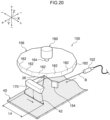
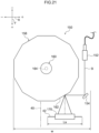
- Figs. 20 and 21 illustrate a laser scanning device 150 according to a comparative example as an example of the polygon mirror type laser scanning device.
- the laser scanning device 150 according to the comparative example includes a laser beam output unit 152, a plane mirror 154, a polygon mirror 156, a motor 160, and a focusing mirror 170.
- the X-axis direction corresponds to the sheet width direction of an electrical steel sheet 40
- the Y-axis direction corresponds to the length direction of the electrical steel sheet 40
- the Z-axis direction corresponds to the sheet thickness direction of the electrical steel sheet 40.
- the electrical steel sheet 40 is passed from the negative side to the positive side in the Y-axis direction.
- the sheet width direction of the electrical steel sheet 40 is referred to as the X-axis direction
- the length direction of the electrical steel sheet 40 is referred to as the Y-axis direction
- the sheet thickness direction of the electrical steel sheet 40 may be referred to as the Z-axis direction.
- the laser beam output unit 152 irradiates a laser beam B
- the plane mirror 154 reflects the laser beam B irradiated from the laser beam output unit 152 toward the polygon mirror 156.
- the polygon mirror 156 is formed in a disk shape using a short polygonal prism, and mirrors are provided on surfaces of the respective surfaces corresponding to the outer peripheral surface, so that a plurality of mirror surfaces 162 are formed.
- the polygon mirror 156 is fixed to a rotation axis 164 of the motor 160 and rotates integrally with the rotation axis 164.
- the rotation axis 164 extends in the normal direction (that is, the Z-axis direction) of a surface of the electrical steel sheet 40, and a rotation plane of the polygon mirror 156 is substantially parallel to the surface of the electrical steel sheet 40 (that is, substantially parallel to the X-Y plane).
- the polygon mirror 156 reflects the laser beam B reflected at the plane mirror 154 toward the focusing mirror 170 by the mirror of the mirror surface 162 that has moved to a position facing the plane mirror 154 in the X-axis direction and facing the focusing mirror 170 in the Y-axis direction among the plurality of mirror surfaces 162.
- the focusing mirror 170 reflects the laser beam B reflected at the mirror surface 162 toward the electrical steel sheet 40 and causes the laser beam B to be focused on the surface of the electrical steel sheet 40.
- Fig. 20 illustrates only the current processed portion 42 for convenience.
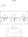
- Fig. 22 is a view illustrating an effective scanning length Ls' of the laser beam B.
- the effective scanning length Ls' corresponds to a beam diameter of the laser beam reflected at the polygon mirror 156 at a time of reaching the electrical steel sheet 40, the beam diameter moving on the surface of the electrical steel sheet along a direction of the rotation axis 164 of the polygon mirror 156 during a period between a beam diameter of the laser beam B, which has a finite beam diameter di and is irradiated from the laser beam output unit 152, at a time of reaching a mirror formed on the mirror surface 162 of the polygon mirror 156 coming into contact with one edge of the mirror until coming into contact with the other end of the mirror as the polygon mirror 156 rotates.
- the beam diameter di of the laser beam B irradiated from the laser beam output unit 152 is generally defined as a diameter at which the intensity is "1/e 2 " of the optical axis central intensity assuming that the intensity distribution of the laser beam B in a direction parallel to the rotation plane of the polygon mirror 156 is a Gaussian distribution, and as a diameter of a region including about 86% of the entire power of the laser beam B, but may be defined, if appropriate, as a diameter of a region including 90% of the entire power, a diameter of a region including 95% of the entire power, or the like.
- Fig. 23 is a view for describing an ideal scanning length Ls" of the laser beam B.
- the ideal scanning length Ls" corresponds to a length of an optical axis at a time when the laser beam reflected at the polygon mirror 156 reaches the electrical steel sheet 40, the optical axis moving on the surface of the electrical steel sheet along the direction of the rotation axis 164 of the polygon mirror 156, during a period between an optical axis at a time when the laser beam B (that is, the laser beam B whose beam diameter can be regarded as a point) irradiated from the laser beam output unit 152 reaches a mirror formed on the mirror surface 162 of the polygon mirror 156 coming into contact with one edge of the mirror until coming into contact with the other end of the mirror as the polygon mirror 156 rotates.
- the power of the laser beam B with which the surface of the electrical steel sheet 40 is irradiated decreases at a timing when an outer shape of the laser beam B passes the boundary and the boundary is located inside the outer shape of the laser beam B, and thus, the effective scanning length Ls' obtained by considering a size of the beam diameter of the laser beam B is shorter than the ideal scanning length Ls" obtained without considering the size of the beam diameter of the laser beam B.
- the number of the laser scanning devices 150 required to scan the plurality of laser beams B in the sheet width direction of the electrical steel sheet 40 increases.
- reflection loss of the laser beam B at the boundary between the plurality of mirror surfaces 162 is determined by a ratio between a tangential length Lm of the mirror surface 162 along a tangential direction of the polygon mirror 156 and the beam diameter di of the laser beam B incident on the mirror surface 162. For example, if the tangential length Lm is sufficiently larger than the beam diameter di, the reflection loss decreases, and the effective scanning length Ls' increases.
- ⁇ is a constant unique to the laser beam B
- ⁇ is a wavelength of the laser beam B
- f is a focal length of the focusing mirror 170.
- the beam diameter di decreases, the focusing performance of the laser beam B decreases, and there is a possibility that it is difficult to form a stress or a groove on the surface of the electrical steel sheet 40.
- the high-output laser beam B is used as in a case in which a groove is formed on the surface of the electrical steel sheet 40, there is a problem that the power density on the mirror surface increases if the beam diameter di is decreased, and a problem of damage of the mirror also occurs. Therefore, there is a limit to decrease the beam diameter di.
- a diameter of the polygon mirror 156 may be increased.
- the rotation plane of the polygon mirror 156 is parallel to the surface of the electrical steel sheet 40.
- the configuration in which light in a direction of the X-Y plane of the beam is focused by the single focusing mirror 170 has been described as a focusing element in the comparative example illustrated in Fig. 20 , but as another method, an f ⁇ lens may be used instead of the focusing mirror 170.
- an f ⁇ lens may be used instead of the focusing mirror 170.
- the first embodiment in the disclosure has been made in view of the above problems, and aims to provide a laser scanning device capable of reducing a width occupied by the laser scanning device as compared with a configuration in which a rotation plane of a polygon mirror is parallel to a surface of an electrical steel sheet as in the laser scanning device according to the comparative example, and further to provide a laser processing device capable of achieving downsizing and cost down by reducing the number of the laser scanning devices required for scanning a plurality of laser beams in a sheet width direction of the electrical steel sheet.
- a surface of a predetermined object is irradiated with a laser beam B to process the surface of the object or modify the surface of the object as will be described later.
- various metal materials can be used.
- an electrical steel sheet 40 can be used, and it is particularly preferable to use a grain-oriented electrical steel sheet, and thus, the following description will be given using the electrical steel sheet 40 as an example of the object.
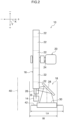
- a laser scanning device 10 includes a laser beam output unit 12, a plane mirror 14, a polygon mirror 16, an optical system 18, and a motor 20.
- the laser beam output unit 12 irradiates the laser beam B irradiated from a laser light source (not illustrated) and transmitted using an optical fiber or the like toward the plane mirror 14 to be described later.
- the laser beam output unit 12 is arranged, for example, on the positive side in the Y-axis direction (in other words, the positive direction side of the Y axis) of the polygon mirror 16 and on the positive side in the Z-axis direction (in other words, the positive direction side of the Z axis) of the electrical steel sheet 40.
- the laser beam output unit 12 is arranged in a direction in which the laser beam B is irradiated toward the negative side in the Z-axis direction (in other words, the negative direction side of the Z axis, that is, the side of the electrical steel sheet 40).
- the plane mirror 14 reflects the laser beam B output from the laser beam output unit 12 and changes the traveling direction of the laser beam B to a direction of a mirror surface 22 of the polygon mirror 16 to be described later.
- the plane mirror 14 is arranged in a space on the lower side (that is, the negative side in the Z-axis direction) of the laser beam output unit 12 and on the upper side (that is, the positive side in the Z-axis direction) of the electrical steel sheet 40, and is arranged on an optical path of the laser beam B between the laser beam output unit 12 and the polygon mirror 16 to be described later.
- the plane mirror 14 is arranged in a direction in which the laser beam B output from the laser beam output unit 12 is reflected to the negative side in the Y-axis direction (that is, the side of the polygon mirror 16).
- the polygon mirror 16 has a polygonal shape having a top surface (that is, an upper surface) and a bottom surface (that is, a lower surface) which are polygonal.
- a top surface that is, an upper surface
- a bottom surface that is, a lower surface
- at least one surface excluding the top surface and the bottom surface is formed as a mirror to form the mirror surface 22.
- the polygon mirror 16 rotates about an axis serving as a rotation axis 24 and penetrating the top surface and the bottom surface.
- the polygon mirror 16 reflects the laser beam B, irradiated from the laser beam output unit 12 and reflected at the plane mirror 14, at the mirror on the mirror surface 22.
- a direction of the laser beam B reflected at the mirror surface 22 changes according to the rotation of the polygon mirror 16, and a position where the laser beam B reaches the surface of the electrical steel sheet 40 through the optical system 18, which will be described later, also changes. Therefore, the surface of the electrical steel sheet 40 can be scanned with the laser beam B according to the rotation of the polygon mirror 16.
- the top surface and the bottom surface of the polygon mirror 16 are polygons, there is a case where the polygons are regarded as circles, and a diagonal line thereof is expressed as an "outer diameter" in the following description.
- the rotation axis 24 of the polygon mirror 16 is fixed to the rotation axis of the motor 20 and rotates integrally.
- the motor 20 may include a speed reduction mechanism connected to the rotation axis 24.
- the rotation axis 24 of the polygon mirror 16 extends in parallel to the surface of the electrical steel sheet 40, and extends, for example, in the X-axis direction.
- a rotation plane of the polygon mirror 16 is the Y-Z plane orthogonal to the X-axis direction when viewed in the Z-axis direction.
- the polygon mirror 16 is arranged at a position where the laser beam B is reflected at a first mirror 26, which will be described later, located on the substantially negative side in the Z-axis direction in a case in which a plurality of the mirror surfaces 22 are located to face the plane mirror 14 in the substantially Y-axis direction and face the first mirror 26 in the substantially Z-axis direction.
- the optical system 18 is an optical element group that guides the laser beam B reflected at the polygon mirror 16 to the surface of the electrical steel sheet 40 which is the object.
- the optical system 18 can be achieved by combining known optical elements as appropriate, and includes, for example, the first mirror 26, a second mirror 28, and a focusing mirror 30.
- the first mirror 26 is arranged on the negative side in the Z-axis direction facing the mirror surface 22 that reflects the laser beam B among the plurality of mirror surfaces 22.
- the first mirror 26 is arranged in a direction in which the laser beam B having been reflected at the mirror surface 22 is reflected toward the positive side in the X-axis direction.
- the first mirror 26 is arranged in a direction in which an optical axis of the first mirror 26 is parallel to the X-axis direction.
- the second mirror 28 is arranged on the positive side in the X-axis direction with respect to the first mirror 26, and is arranged in a direction in which the laser beam B having been reflected at the first mirror 26 is reflected to the positive side in the Y-axis direction.
- the second mirror 28 is arranged in a direction in which an optical axis of the second mirror 28 is parallel to the Y-axis direction.
- the focusing mirror 30 is, for example, a focusing parabolic mirror.
- the focusing mirror 30 is arranged on the positive side in the Y-axis direction with respect to the second mirror 28 and on the positive side in the Z-axis direction with respect to the electrical steel sheet 40.
- the focusing mirror 30 is arranged in a direction in which the laser beam B having been reflected at the second mirror 28 is reflected to the negative side in the Z-axis direction (that is, the side of the electrical steel sheet 40).
- the focusing mirror 30 is arranged in a direction in which an optical axis of the focusing mirror 30 is parallel to the Z-axis direction.
- a position of the focusing mirror 30 is set to a position where the incident laser beam B is focused on the surface of the electrical steel sheet 40.
- the focusing mirror 30 is formed in an elongated shape.
- a direction of the focusing mirror 30 is set such that the longitudinal direction of the focusing mirror 30 is parallel to the X-axis direction when viewed in the Z-axis direction, whereby a scanning direction of the laser beam B is set to be substantially parallel to the X-axis direction.
- the optical system 18 can guide the laser beam B reflected at the polygon mirror 16 to the surface of the electrical steel sheet 40, and can change a position irradiated with the laser beam B on the surface of the electrical steel sheet 40 in parallel to the X-axis direction, for example, according to the rotation of the polygon mirror 16. That is, the surface of the electrical steel sheet 40, which is the object, can be scanned with the laser beam B, and it is possible to process the surface of the electrical steel sheet 40 or modify the surface of the electrical steel sheet 40.
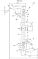
- the rotation axis 24 of the polygon mirror 16 is oriented in the X-axis direction as illustrated in Fig. 1
- the surface of the electrical steel sheet 40 is scanned with the laser beam B irradiated from the optical system 18, in particular, the focusing mirror 30 in a direction along the X-axis direction. That is, the direction of the rotation axis 24 of the polygon mirror 16 and the scanning direction are parallel. In other words, the rotation axis 24 extends along the direction in which the laser beam B is scanned.
- a width occupied by the polygon mirror 16 in the width direction of the electrical steel sheet 40 can be made relatively smaller than a scannable width. That is, the width occupied by one laser scanning device 10 can be reduced.
- the laser scanning device 10 performs processing of scanning the surface of the electrical steel sheet 40 with the laser beam B, and is executed by the laser scanning device 10.
- the laser scanning device 10 when the laser beam B is irradiated from the laser beam output unit 12 toward the plane mirror 14, the laser beam B is reflected at the plane mirror 14 to the negative side in the Y-axis direction (that is, the side of the polygon mirror 16).
- the motor 20 is operated to rotate the polygon mirror 16 integrally with the rotation axis 24 of the motor 20, and the laser beam B irradiated from the laser beam output unit 12 is reflected at the mirror of the mirror surface 22 of the polygon mirror 16.
- the laser beam B having been reflected at the mirror of the mirror surface 22 is reflected at the first mirror 26 to the positive side in the X-axis direction, and the laser beam B having been reflected at the first mirror 26 is reflected at the second mirror 28 to the positive side in the Y-axis direction.
- the laser beam B having been reflected at the second mirror 28 is reflected at the focusing mirror 30 to be focused on the surface of the electrical steel sheet 40. That is, the laser beam B reflected at the polygon mirror 16 is guided to the surface of the electrical steel sheet 40.
- a reflection angle of the laser beam B reflected at the mirror surface 22 continuously changes, and an incident position of the laser beam B incident on the first mirror 26, an incident position of the laser beam B incident on the second mirror 28, and an incident position of the laser beam B incident on the focusing mirror 30 each change.
- the laser beam B is irradiated in the X-axis direction, and the surface of the electrical steel sheet 40 is irradiated with the laser beam B, so that a processed portion 42, which is a linear stress or groove, is formed on the surface of the electrical steel sheet 40.
- the mirror surface 22 that reflects the laser beam B is switched to the next mirror surface 22 with the rotation of the polygon mirror 16, so that the next processed portion 42 is formed on the surface of the electrical steel sheet 40 at a regular interval in the Y-axis direction from the current processed portion 42.
- Fig. 1 illustrates only the current processed portion 42 for convenience.
- the rotation plane (that is, the Y-Z plane) of the polygon mirror 16 is orthogonal to the X-axis direction.
- the width W of the laser scanning device 10 according to the first embodiment is narrower than the width (that is, width occupied in the width direction of the electrical steel sheet 40) w of the laser scanning device 150 according to the comparative example illustrated in Fig. 21 .
- the laser scanning device 10 according to the first embodiment satisfies W ⁇ Ls in the relationship between the width W and the effective scanning length Ls.
- a diameter of the polygon mirror 16 is preferably 400 mm or more, but the width W of the laser irradiation device does not depend on the diameter of the polygon mirror and is, for example, about 150 mm in the example according to the present invention.
- the width W is a width (that is, width occupied in the width direction of the electrical steel sheet 40) of the laser scanning device 10 along the X-axis direction.
- the width W corresponds to the maximum width between an end on the positive side and an end on the negative side in the X-axis direction of the laser scanning device 10.
- the effective scanning length Ls is a beam diameter of the laser beam B reflected at the polygon mirror 16 at a time of reaching the electrical steel sheet 40, the beam diameter moving on the surface of the electrical steel sheet 40, during a period between a beam diameter of the laser beam B irradiated from the laser beam output unit 12 at a time of reaching a mirror formed on the polygon mirror 16 coming into contact with one edge of the mirror until coming into contact with the other end of the mirror as the polygon mirror 16 rotates.
- the effective scanning length Ls is defined by a length along the direction of the rotation axis 24 of the polygon mirror 16.
- the effective scanning length Ls corresponds to a length of the processed portion 42 in the X-axis direction.
- the range of the width W of the laser scanning device 10 may protrude from the range of the effective scanning length Ls as long as the relationship of W ⁇ Ls is satisfied.
- the laser irradiation devices can be arranged in a line in the width direction, and space-saving and compact equipment can be configured.
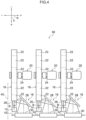
- the laser processing device 50 includes a plurality of the laser scanning devices 10.
- the plurality of laser scanning devices 10 are arranged side by side in the X-axis direction. Positions of the plurality of laser scanning devices 10 are set to positions at which the processed portions 42 are formed to be continuous in the X-axis direction or the processed portion 42 are formed to partially overlap each other in the X-axis direction by the adjacent laser scanning devices 10.
- the adjacent laser scanning devices 10 are controlled to perform scanning with the laser beams B in the same direction and/or controlled to shift scanning timings of the laser beams B in order to avoid interference between the two laser beams B with which the surface of the electrical steel sheet 40 is irradiated by the adjacent laser scanning devices 10.
- Fig. 4 illustrates three laser scanning devices 10 as an example, the number of the plurality of laser scanning devices 10 included in the laser processing device 50 only needs to be two or more and may be any number.
- the laser processing device 50 can reduce a width occupied by each of the laser scanning devices 10 in the width direction of the electrical steel sheet 40 with respect to a scanning width by using the laser scanning devices 10, the laser processing device 50 as a whole can be configured to be compact.
- the electrical steel sheet manufacturing method according to the first embodiment is an electrical steel sheet manufacturing method using the laser scanning device 10 according to the first embodiment, and includes a hot rolling step, a cold rolling step, a primary recrystallization annealing step, a secondary recrystallization annealing step, a coating step, and a laser processing step.
- the hot rolling step a slab is hot-rolled to produce a hot-rolled steel sheet.
- the hot-rolled steel sheet is cold-rolled to produce a cold-rolled steel sheet.
- the primary recrystallization annealing step the cold-rolled steel sheet is subjected to decarburization annealing to develop primary recrystallization in the cold-rolled steel sheet.
- the secondary recrystallization annealing step the cold-rolled steel sheet after the decarburization annealing is subjected to finish annealing to develop secondary recrystallization in the cold-rolled steel sheet, thereby forming the cold-rolled steel sheet into the electrical steel sheet 40.
- the coating step coating is performed on the electrical steel sheet 40 after the finish annealing.
- the laser processing step is performed after the secondary recrystallization step as an example.
- the surface of the electrical steel sheet 40 is scanned and irradiated with the laser beam B to form the processed portion 42 on the surface of the electrical steel sheet 40.
- a laser processing method using the laser processing device 50 illustrated in Fig. 4 is executed.
- the laser beam B is output from the laser beam output unit 12 in each of the plurality of laser scanning devices 10 arranged side by side in the X-axis direction, the laser beam B output from the laser beam output unit 12 is reflected at the plane mirror 14, the laser beam B having been reflected at the plane mirror 14 is reflected at the polygon mirror 16 while rotating the polygon mirror 16, and the laser beam B having been reflected at the polygon mirror 16 is guided to the surface of the electrical steel sheet 40 by the optical system 18.
- the processed portion 42 which is the stress or groove, is formed on the surface of the electrical steel sheet 40 over the sheet width direction.
- the above-described laser processing method is repeatedly executed while passing the electrical steel sheet 40, whereby a plurality of the processed portions 42 continuous in the X-axis direction or partially overlapping each other in the X-axis direction are formed at regular intervals in the length direction of the electrical steel sheet 40.
- the rotation axis 24 extends in the X-axis direction, and the rotation plane of the polygon mirror 16 is orthogonal to the X-axis direction when viewed in the Z-axis direction in the laser scanning device 10 according to the first embodiment. Therefore, in the laser scanning device 10 according to the first embodiment illustrated in Fig. 2 , the width W occupied by the laser scanning device 10 along the X-axis direction can be reduced, for example, as compared with a case in which the rotation plane of the polygon mirror 156 is parallel to the surface of the electrical steel sheet 40 as in the laser scanning device 150 according to the comparative example illustrated in Fig. 20 .
- the width W of the laser scanning device 10 can be made smaller than the effective scanning length Ls since the rotation plane of the polygon mirror 16 is orthogonal to the X-axis direction when viewed in the Z-axis direction in the laser scanning device 10 according to the first embodiment. Therefore, the plurality of laser scanning devices 10 can be arranged side by side in the X-axis direction while avoiding interference between the adjacent laser scanning devices 10 in the laser processing device 50 including the plurality of laser scanning devices 10. As a result, it is possible to achieve downsizing and cost down of the laser processing device 50 including the plurality of laser scanning devices 10 with the laser processing device 50 according to the first embodiment illustrated in Fig.
- the laser processing step is performed after the secondary recrystallization step as an example in the first embodiment, but may be performed after any one of the cold rolling step, the primary recrystallization annealing step, and the coating step.
- the laser processing step may be performed after the coating step in a case in which a stress is formed on the surface of the electrical steel sheet 40 in the laser processing step.
- a recoating step may be performed after the laser processing step if necessary.
- the cold-rolled steel sheet corresponds to an example of an "object” and a "steel sheet formed on an electrical steel sheet" in the disclosure.
- the laser scanning device 10, the laser scanning method, the laser processing device 50, and the laser processing method are applied to laser processing of the electrical steel sheet in the first embodiment, but may be applied to laser processing of an object other than the electrical steel sheet.
- the laser scanning device 10 and the laser scanning method may be applied to applications other than the laser processing.
- the laser scanning device 10 includes the plane mirror 14 that reflects the laser beam B output from the laser beam output unit 12 toward the polygon mirror 16 in the first embodiment, the plane mirror 14 may be omitted. Further, a position of the laser beam output unit 12 may be set to a position to output the laser beam B toward the polygon mirror 16.
- the laser beam output unit 12, the plane mirror 14, the first mirror 26, the second mirror 28, and the focusing mirror 30 may be arranged differently from the above.
- the optical system 18 includes the first mirror 26, the second mirror 28, and the focusing mirror 30, but may include optical components other than the first mirror 26, the second mirror 28, and the focusing mirror 30.
- the optical system 18 includes the focusing mirror 30, but may include an f ⁇ lens instead of the focusing mirror 30.
- the surface of the electrical steel sheet 40 passed in the horizontal direction is irradiated with the laser beam B by the laser scanning device 10 in the first embodiment
- the surface of the electrical steel sheet 40 passed in the vertical direction or an inclined direction with respect to the vertical direction may be irradiated with the laser beam B by the laser scanning device 10.
- the plurality of laser scanning devices 10 arranged in the X-axis direction are arranged at the same position in the Y-axis direction in the laser processing device 50 according to the first embodiment, some laser scanning devices 10 among the plurality of laser scanning devices 10 arranged in the X-axis direction may be arranged to be shifted in the Y-axis direction with respect to the other laser scanning devices 10.
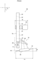
- a laser scanning device 60 according to the second embodiment illustrated in Figs. 5 and 6 is different from the laser scanning device 10 according to the first embodiment illustrated in Figs. 1 and 2 in terms of the following configuration.
- the longitudinal direction of a focusing mirror 30 is inclined with respect to the X-axis direction when viewed in the Z-axis direction, whereby a scanning direction of a laser beam B is inclined with respect to the X-axis direction when viewed in the Z-axis direction.
- a rotation axis 24 of a polygon mirror 16 is oriented in a direction intersecting the scanning direction of the laser beam B when viewed in the normal direction of a surface of the electrical steel sheet 40 which is an object. That is, in the disclosure, the rotation axis 24 is regarded to be substantially parallel to the scanning direction even in a case in which the rotation axis 24 of the polygon mirror 16 is oriented in the direction intersecting the scanning direction of the laser beam B when viewed in the normal direction of the surface of the electrical steel sheet 40. In other words, the rotation axis 24 extends along the direction in which the laser beam B is scanned.
- a first inclination angle ⁇ 1 between the scanning direction of the laser beam B and the X-axis direction is set to, for example, 0° ⁇ ⁇ ⁇ 45°.
- the first inclination angle ⁇ 1 When the first inclination angle ⁇ 1 is larger than 0°, a processed portion 42 formed on the surface of the electrical steel sheet 40 can be inclined with respect to the X-axis direction. Therefore, in a case in which the electrical steel sheet 40 is subjected to bending, it is possible to suppress fracture of the electrical steel sheet 40 starting from the processed portion 42.
- the first inclination angle ⁇ 1 is smaller than 45°, it is possible to ensure an effect of reducing iron loss by formation of the processed portion 42 on the surface of the electrical steel sheet 40. Note that it is more preferable that the first inclination angle ⁇ 1 is from 5° to 10°.
- the laser beam B is scanned in the inclination direction with respect to the X-axis direction, but an effective scanning length Ls is defined by a length of the laser beam B along the X-axis direction as described above.
- the effective scanning length Ls is calculated as L ⁇ cos ⁇ .
- a rotation plane (that is, the Y-Z plane) of the polygon mirror 16 intersects the X-axis direction when viewed in the Z-axis direction as illustrated in Fig. 6 .
- a width W of the laser scanning device 60 according to the second embodiment is narrower than the width w of the laser scanning device 150 according to the comparative example illustrated in Fig. 21 .
- the laser scanning device 60 according to the second embodiment satisfies W ⁇ Ls in a relationship between the width W and the effective scanning length Ls.
- the width W is a width of the laser scanning device 60 along the X-axis direction.
- the width W corresponds to a width between an end on the positive side and an end on the negative side in the X-axis direction of the laser scanning device 60.
- the end on the positive side and the end on the negative side in the X-axis direction of the laser scanning device 60 may be any portion of the laser scanning device 60.
- a laser processing device 70 includes a plurality of the laser scanning devices 60.
- the plurality of laser scanning devices 60 are arranged side by side in the X-axis direction. Positions of the plurality of laser scanning devices 60 are set to positions where the processed portions 42 are formed to partially overlap each other in the X-axis direction by the adjacent laser scanning devices 60.
- An overlap length Wo corresponds to a length by which the processed portions 42 formed adj acent to each other in the X-axis direction partially overlap each other in the X-axis direction.
- Some of the processed portions 42 adjacent to each other in the X-axis direction are formed to be separated in the Y-axis direction.
- Fig. 7 illustrates three laser scanning devices 60 as an example, the number of the plurality of laser scanning devices 60 included in the laser processing device 70 only needs to be two or more and may be any number.
- a laser scanning method and a laser processing method according to the second embodiment are similar to the laser scanning method and the laser processing method according to the first embodiment described above except that the laser beam B is scanned in the inclination direction with respect to the X-axis direction, and the description thereof will be omitted.
- the laser beam B is scanned in the inclination direction with respect to the X-axis direction, and thus, the processed portion 42, which is a linear stress or groove formed on the surface of the electrical steel sheet 40, can be inclined with respect to the X-axis direction. Therefore, even in a case in which the electrical steel sheet 40 is subjected to bending, it is possible to suppress fracture of the electrical steel sheet 40 starting from the processed portion 42.
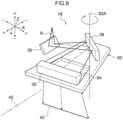
- an optical system 18 may include a first rotary member 62.
- the first rotary member 62 has a sheet shape and an isosceles trapezoidal shape in plan view. In the disclosure, the shape of the first rotary member 62 can be changed, if appropriate.
- the first rotary member 62 is supported by a rotation supporting mechanism (not illustrated) to be rotatable along the X-Y plane about a rotation center 62A.
- the first rotation center 62A is located on an optical axis of a first mirror 26 and on a reflective surface of a second mirror 28 when viewed in the Z-axis direction.
- first rotary member 62 rotates, a distance on the optical axis center between the first mirror 26 and the second mirror 28 is the same.
- first rotary member 62 rotates along a plane including an optical path of the laser beam B between the second mirror 28 and the focusing mirror 30.
- the second mirror 28 and the focusing mirror 30 are fixed on an upper surface of the first rotary member 62.
- a hole 64 through which the laser beam B reflected at the focusing mirror 30 passes is formed in the first rotary member 62.
- the hole 64 has an isosceles trapezoidal shape in plan view.
- the second mirror 28 corresponds to a reflecting mirror according to the disclosure. In the disclosure, the shape of the hole 64 can be changed, if appropriate.
- the optical system 18 according to the second embodiment includes the first rotary member 62 in this manner, the first inclination angle ⁇ 1 between the scanning direction of the laser beam B and the X-axis direction can be adjusted.
- the first rotary member 62 supports the second mirror 28 and the focusing mirror 30 so as to fix a relative position between the second mirror 28 and the focusing mirror 30.
- the change in the position of the second mirror 28 can be interlocked with a change in a position of the focusing mirror 30 due to the rotation of the first rotary member 62.
- the predetermined first inclination angle ⁇ 1 may be formed by rotating the first rotary member 62 in advance before the start of scanning with the laser beam B.
- the first inclination angle ⁇ 1 may be changed, if necessary, due to a change in a sheet passing speed or by an angle rotating device (not illustrated).
- the scanning direction when the scanning direction is to be changed as necessary, it is unnecessary to individually adjust the second mirror 28 and the focusing mirror 30, and the scanning direction can be easily changed only by the rotation of the first rotary member 62.
- a position of the laser beam incident on a reflective surface of the focusing mirror 30 is constant since the relative positional relationship between the second mirror 28 and the focusing mirror 30 is fixed.
- focusing property does not change before and after the change in the scanning direction, and stable processing can be performed.
- the optical system 18 may include a second rotary member 63.
- the second rotary member 63 has a sheet shape and a rectangular shape in plan view. In the disclosure, the shape of the second rotary member 63 can be changed, if appropriate.
- the first mirror 26 is installed on an upper surface at a position of one end (left end in Fig. 10 ) corresponding to a lower side of a polygon mirror (not illustrated).
- the second rotary member 63 is supported by a rotation supporting mechanism (not illustrated) to be rotatable along the Z-X plane about a second rotation center 63A.
- the second rotation center 63A is located on an optical axis of the second mirror 28 and on a reflective surface on the plane of the first mirror 26 when viewed in the Y-axis direction.
- the second rotary member 63 has a function of rotating about an axis of the second rotation center 63A. Even when the second rotary member 63 rotates, a distance on the optical axis between the first mirror 26 and the second mirror 28 is the same. As the second rotary member 63 rotates, the plane including an optical path of the laser beam B between the first mirror 26 and the second mirror 28 rotates to be closed to or separated from the X-Y plane in Fig. 10 , that is, the surface of the electrical steel sheet 40.
- first rotary member 63 is supported to be rotatable along the X-Y plane about the first rotation center 62A at a position separated from the first mirror 26 on the upper surface of the second rotary member 62 in Fig. 10 .
- the first rotary member 62 according to the second modification in Fig. 10 is different from the first rotary member 62 described in the first modification in that the first rotary member has a rectangular shape in plan view and that the hole 64 has a rectangular shape. Note that the shape of the hole 64 can be changed, if appropriate, in the second rotary member 63 of the second modification as well.
- Other configurations of the first rotary member 62 according to the second modification are similar to those of the first rotary member 62 according to the first modification.
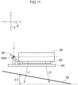
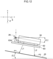
- a first distance L1 between a scanning start position P1 on the surface of the electrical steel sheet 40 and a reflection point of the focusing mirror 30 and a second distance L2 between a scanning end position P2 on the surface of the electrical steel sheet 40 and the reflection point of the focusing mirror 30 are set.
- the first distance L1 and the second distance L2 coincide with a focal length of the focusing mirror 30
- no focus blur occurs over the entire length of scanning lines between the scanning start position P1 and the scanning end position P2.
- the surface of the electrical steel sheet 40 is inclined with respect to the horizontal direction to form a second inclination angle ⁇ 2 between the surface of the electrical steel sheet 40 and the X-axis direction as illustrated in Fig. 11 , the first distance L1 and the second distance L2 are different.
- the first distance L1 and the second distance L2 can be controlled to coincide with the focal length of the focusing mirror 30 since the second rotary member 63 is rotated at the second inclination angle ⁇ 2 in the second modification as illustrated in Fig. 12 .
- the predetermined second inclination angle ⁇ 2 may be formed by rotating the second rotary member 63 in advance before the start of scanning with the laser beam B.
- a variation in inclination may be detected as needed by a steel sheet inclination measuring device (not illustrated) to change the second inclination angle ⁇ 2 as needed.
- uniform laser processing can be performed over the entire width in the scanning direction of the laser beam B on the surface of the electrical steel sheet 40 in the second modification.
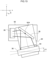
- the second rotary member 63 is provided with the first rotary member 62 as illustrated in Fig. 13 , a position of the second mirror 28 and a position of the focusing mirror 30 integrally change even in a case in which a position of the second mirror 28 changes to form the first inclination angle ⁇ 1 between the scanning direction and the X-axis direction.
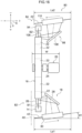
- the surface of the electrical steel sheet 40 can be subjected to laser processing while suppressing the occurrence of focus blur as illustrated in Fig. 14 , which is similar to the first modification.
- the first mirror 26, the second mirror 28, and the focusing mirror 30 may be provided in the second rotary member 63 without providing the first rotary member 62.
- a laser scanning device 80 according to the third embodiment illustrated in Figs. 15 and 16 is different from the laser scanning device 60 according to the second embodiment illustrated in Figs. 5 and 6 in terms of the following configuration.
- the laser scanning device 80 includes a first laser scanning unit 82, a second laser scanning unit 84, a polygon mirror 16, and a motor 20.
- the first laser scanning unit 82 includes a laser beam output unit 12, a plane mirror 14, and an optical system 18.
- the laser beam output unit 12, the plane mirror 14, and the optical system 18 constituting the first laser scanning unit 82 have the same configurations as those of the second embodiment described above.
- the polygon mirror 16 and the motor 20 have the same configurations as those of the second embodiment described above.
- the laser beam output unit 12 outputs a first laser beam B1.
- the first laser beam B1 is irradiated to surface of an electrical steel sheet 40 via the plane mirror 14, the polygon mirror 16, and the optical system 18.
- the second laser scanning unit 84 includes a laser beam output unit 92, a mirror 94, and an optical system 98.
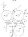
- the optical system 98 includes a first mirror 106, a second mirror 108, and a focusing mirror 110.
- the laser beam output unit 92, the mirror 94, the first mirror 106, the second mirror 108, and the focusing mirror 110 are arranged at positions symmetrical with the laser beam output unit 12, the plane mirror 14, a first mirror 26, a second mirror 28, and a focusing mirror 30 in the Y-axis direction with respect to a rotation axis 24.
- the laser beam output unit 92, the mirror 94, the first mirror 106, the second mirror 108, and the focusing mirror 110 have the same configurations as the laser beam output unit 12, the plane mirror 14, the first mirror 26, the second mirror 28, and the focusing mirror 30, respectively.
- the laser beam output unit 92 outputs a second laser beam B2.
- the second laser beam B2 output from the laser beam output unit 92 is irradiated to the surface of the electrical steel sheet 40 via the mirror 94, the polygon mirror 96, and the optical system 98 similarly to the irradiation of the surface of the electrical steel sheet 40 with the first laser beam B1 output from the laser beam output unit 12 via the plane mirror 14, the polygon mirror 16, and the optical system 18.
- the second laser beam B2 is scanned in a direction opposite to that of the first laser beam B 1.
- Orientations of the second mirror 108 and the focusing mirror 110 are set to orientations with which a scanning direction of the second laser beam B2 is parallel to a scanning direction of the first laser beam B1.
- positions of the second mirror 108 and the focusing mirror 110 are set to positions at which a position and a length in the X-axis direction of a processed portion 42 formed by the second laser beam B2 are the same as a position and a length in the X-axis direction of a processed portion 42 formed by the first laser beam B1.
- An effective scanning length Ls 1 of the first laser beam B1 and an effective scanning length Ls2 of the second laser beam B2 are the same.
- an outer diameter of the polygon mirror 16 and/or an arrangement position of the optical system 18 are set such that the processed portion 42 formed by the second laser beam B2 is formed at the center between a plurality of the processed portions 42 formed by the first laser beams B1. That is, in a case in which a pitch of the plurality of processed portions 42 is denoted by PL, an interval between the processed portion 42 formed by the first laser beam B1 and the processed portion 42 formed by the second laser beam B2 is denoted by G, and n is an integer of 0 or more in the laser scanning device 80 according to the third embodiment, the following Formula (2) is satisfied.
- G 2 n + 1 ⁇ PL
- a laser processing device 120 includes a plurality of the laser scanning devices 80.
- the plurality of laser scanning devices 80 are arranged side by side in the X-axis direction. Positions of the plurality of laser scanning devices 80 are set to positions where the processed portions 42 are formed to partially overlap each other in the X-axis direction by the adjacent laser scanning devices 80.
- An overlap length Wo corresponds to a length by which the processed portions 42 formed adj acent to each other in the X-axis direction partially overlap each other in the X-axis direction.
- Some of the processed portions 42 adjacent to each other in the X-axis direction are formed to be separated in the Y-axis direction.
- Fig. 17 illustrates two laser scanning devices 80 as an example, the number of the plurality of laser scanning devices 80 included in the laser processing device 120 only needs to be two or more and may be any number.
- a laser scanning method and a laser processing method according to the third embodiment are similar to the laser scanning method and the laser processing method according to the second embodiment described above except that the surface of the electrical steel sheet 40 is irradiated with the first laser beam B 1 and the second laser beam B2 by one laser scanning device 80, and the description thereof will be omitted.
- the surface of the electrical steel sheet 40 is irradiated with the first laser beam B 1 and the second laser beam B2 on both the sides in the Y-axis direction with respect to the polygon mirror 16, the processed portions 42 can be formed on both the sides in the Y-axis direction with respect to the polygon mirror 16. Therefore, it is possible to improve the processing efficiency when the plurality of processed portions 42 are formed on the surface of the electrical steel sheet 40, for example, as compared with a case in which the processed portions 42 are formed on one side in the Y-axis direction with respect to the polygon mirror 16.
- each of the pitch of the processed portion 42 formed by the first laser scanning unit 82 and the pitch of the processed portion 42 formed by the second laser scanning unit 84 can be increased as compared with a case in which the processed portions 42 are formed on one side in the Y-axis direction with respect to the polygon mirror 16 when the pitches of the processed portions 42 are made the same and compared. Therefore, the time required for forming one processed portion 42 can be increased, and thus, each of the effective scanning length Ls of the first laser beam B1 and the effective scanning length Ls of the second laser beam B2 can be increased. As a result, it is possible to improve the processing efficiency when the plurality of processed portions 42 are formed on the surface of the electrical steel sheet 40.
- each of the first laser beam B1 and the second laser beam B2 is scanned in an inclination direction with respect to the X-axis direction, but each of the first laser beam B1 and the second laser beam B2 may be scanned in the X-axis direction similarly to the laser beam B of the first embodiment.
- a laser scanning device 130 according to the fourth embodiment illustrated in Figs. 18 and 19 is different from the laser scanning device 80 according to the third embodiment illustrated in Figs. 15 and 16 in terms of the following configuration.
- a second laser scanning unit 84 is configured to be point-symmetrical with a first laser scanning unit 82 about a center point 16A of a polygon mirror 16 when viewed in the Z-axis direction.
- a second mirror 28 and a focusing mirror 30 of the first laser scanning unit 82 are arranged on the positive side in the X-axis direction and the positive side in the Y-axis direction with respect to the polygon mirror 16
- a second mirror 108 and a focusing mirror 110 of the second laser scanning unit 84 are arranged on the negative side in the X-axis direction and the negative side in the Y-axis direction with respect to the polygon mirror 16.
- a second laser beam B2 is scanned in a direction opposite to that of a first laser beam B1.
- orientations of the second mirror 108 and the focusing mirror 110 are set to orientations with which a scanning direction of the second laser beam B2 is parallel to a scanning direction of the first laser beam B1. Furthermore, positions of the second mirror 108 and the focusing mirror 110 are set to positions at which a length in the X-axis direction of a processed portion 42 formed by the second laser beam B2 is the same as a length in the X-axis direction of a processed portion 42 formed by the first laser beam B1.
- An effective scanning length Ls1 of the first laser beam B1 and an effective scanning length Ls2 of the second laser beam B2 are the same.
- a laser processing device 140 includes a plurality of the laser scanning devices 130.
- the plurality of laser scanning devices 130 are arranged side by side in the X-axis direction. Positions of the plurality of laser scanning devices 130 are set to positions where the processed portions 42 are formed to partially overlap each other in the X-axis direction by the adjacent laser scanning devices 130.
- An overlap length Wo corresponds to a length by which the processed portions 42 formed adj acent to each other in the X-axis direction partially overlap each other in the X-axis direction.
- Some of the processed portions 42 adjacent to each other in the X-axis direction are formed to be separated in the Y-axis direction.
- the laser scanning device 130 satisfies W ⁇ Ls1 + Ls2 - Wo in a relationship among a width W, an effective scanning length Ls1 of the first laser beam B1, an effective scanning length Ls2 of the second laser beam B2, and an overlap length Wo.
- Fig. 19 illustrates two laser scanning devices 130 as an example, the number of the plurality of laser scanning devices 130 included in the laser processing device 140 only needs to be two or more and may be any number.
- a laser scanning method and a laser processing method according to the fourth embodiment are similar to the laser scanning method and the laser processing method according to the third embodiment described above except that the second laser scanning unit 84 is configured to be point-symmetrical with the first laser scanning unit 82 so that a position of the processed portion 42 formed by the second laser beam B2 is point-symmetrical with a position of the processed portion 42 formed by the first laser beam B1, and the description thereof will be omitted.
- the processed portions 42 can be formed on both the sides in the X-axis direction with respect to the polygon mirror 16. Therefore, the processed portion 42 can be formed in a wide range in the X-axis direction by one laser scanning device 10, for example, as compared with a case in which the processed portion 42 is formed on one side in the X-axis direction with respect to the polygon mirror 16.
- the laser scanning device 130 can be downsized as compared with a case in which the processed portion 42 is formed on one side in the X-axis direction with respect to the polygon mirror 16 by one laser scanning device 130 when lengths of the processed portions 42 formed by one laser scanning device 130 are made the same and compared.
- each of the first laser beam B 1 and the second laser beam B2 is scanned in an inclination direction with respect to the X-axis direction, but each of the first laser beam B 1 and the second laser beam B2 may be scanned in the X-axis direction similarly to the laser beam B of the first embodiment.
- Aspect 1 is a laser scanning device that scans a surface of an object with a laser beam, the laser scanning device including:
- Aspect 2 is the laser scanning device according to Aspect 1, in which, in a case in which:
- Aspect 3 is the laser scanning device according to Aspect 1 or 2, in which the optical system includes:
- Aspect 4 is a laser scanning method of scanning a surface of an object with a laser beam, the laser scanning method including:
- Aspect 5 is a laser processing device including a plurality of the laser scanning devices according to Aspect 1 arranged side by side in a sheet width direction of an electrical steel sheet or a steel sheet formed on the electrical steel sheet such that a surface of the electrical steel sheet or the steel sheet formed on the electrical steel sheet is scanned and processed with the laser beam.
- Aspect 6 is an electrical steel sheet manufacturing method including:
- another Aspect 1 is a laser scanning device that scans a surface of an object with a laser beam, the laser scanning device including:
- Another Aspect 2 is the laser scanning device according to another Aspect 1, in which, in a case in which:
- Another Aspect 3 is a laser scanning method of scanning a surface of an object with a laser beam, the laser scanning method including:
- Another Aspect 4 is a laser processing device including a plurality of the laser scanning devices according to another Aspect 1 arranged side by side in a sheet width direction of an electrical steel sheet or a steel sheet formed on the electrical steel sheet such that a surface of the electrical steel sheet or the steel sheet formed on the electrical steel sheet is scanned and processed with the laser beam.
- Another Aspect 5 is an electrical steel sheet manufacturing method including:
- the width occupied by the laser scanning device as compared with the conventional laser scanning device exemplified by the laser scanning device or the like in which the rotation plane of the polygon mirror is substantially parallel to the surface of the object.
Landscapes
- Physics & Mathematics (AREA)
- Optics & Photonics (AREA)
- Engineering & Computer Science (AREA)
- Mechanical Engineering (AREA)
- Plasma & Fusion (AREA)
- Chemical & Material Sciences (AREA)
- General Physics & Mathematics (AREA)
- Crystallography & Structural Chemistry (AREA)
- Thermal Sciences (AREA)
- Materials Engineering (AREA)
- Metallurgy (AREA)
- Organic Chemistry (AREA)
- Electromagnetism (AREA)
- Manufacturing & Machinery (AREA)
- Laser Beam Processing (AREA)
- Mechanical Optical Scanning Systems (AREA)
- Optical Elements Other Than Lenses (AREA)
- Manufacturing Of Steel Electrode Plates (AREA)
Abstract
Description
- The present disclosure relates to a laser scanning device, a laser scanning method, a laser processing device, and an electrical steel sheet manufacturing method.
- Conventionally, there have been known laser scanning devices irradiating surfaces of objects with laser beams and scanning the surfaces of the objects with the laser beams to process the surfaces of the objects or modify the surfaces of the objects. Such laser scanning devices include one provided with a laser beam output unit that outputs a laser beam, a polygon mirror that is fixed to a rotation axis and reflects the laser beam output from the laser beam output unit, and an optical system that guides the laser beam reflected at the polygon mirror to a surface of an object, for example, as described in
Fig. 2 of Japanese National-Phase Publication (JP-A) No. 2018-507111 - Patent Literature 1: Japanese National-Phase Publication (
JP-A) No. 2018-507111 - By the way, in an electrical steel sheet manufacturing method, magnetic domain control is known in which a strip-shaped steel sheet is continuously passed, and a surface of the steel sheet is scanned and irradiated with a laser beam in substantially parallel with the sheet width direction to form a thermal stress or a groove, thereby improving iron loss. In this manufacturing method, a scanning direction of the laser beam is one direction in the sheet width direction, and a rotating polygon mirror is most suitable as a scanning device of the unidirectional laser beam.
- Note that a sheet width of the electrical steel sheet is usually 1000 mm or more, and a scanning width of a laser irradiation device is about 150 to 200 mm. Therefore, five to seven laser irradiation devices are required. When adjacent scanning lines are separated from each other so that a non-laser-irradiated portion is generated in the sheet width direction, the effect of reducing the iron loss greatly decreases. Thus, it is necessary to arrange the laser irradiation devices such that the adjacent irradiation lines have no gap or overlap each other by several mm. At this time, if the entire width of the laser irradiation device is wider than the scanning width of the laser, it is necessary to arrange the laser irradiation device to extend in the sheet passing direction of the sheet in order to make the adjacent scanning lines overlap each other, and thus, there is a problem that equipment is increased in size.
- Therefore, it is preferable that the width of the laser scanning line per device is as wide as possible, but in a scanning optical system using reflection of a polygon mirror, there is a problem that power reflection loss of a laser beam having a finite diameter occurs between adjacent mirrors (that is, corners of the mirrors) of the polygon mirror that is a polyhedron. In order to reduce this loss, it is necessary to relatively increase a reflection surface length of the polygon mirror in the circumferential direction with respect to the diameter of the beam incident on the polygon mirror. That is, it is necessary to increase a diameter of the polygon mirror.
- Here, in a case in which the rotation axis of the polygon mirror is orthogonal to the laser scanning direction, that is, in a case in which a rotation surface of the polygon mirror is parallel to a scanning surface and the diameter of the polygon mirror is large, the width of the laser irradiation device in the scanning direction becomes larger than the diameter of the polygon mirror, and as a result, the width occupied by the laser scanning device increases. Therefore, it is necessary to arrange the laser irradiation device so as to extend in the sheet passing direction in order to arrange the laser scanning lines on the surface of the electrical steel sheet without any gap in the sheet width direction, and there is a problem that the equipment is increased in size.
- The disclosure aims to reduce a width occupied by a laser scanning device as compared with a conventional laser scanning device exemplified by a laser scanning device or the like in which a rotation plane of a polygon mirror is parallel to a surface of an object, and to enable a plurality of laser scanning lines to be arranged compactly in the sheet width direction.
- In order to solve the above problem, a laser scanning device according to a first aspect of the disclosure is a laser scanning device that scans a surface of an object with a laser beam, and includes: a laser beam output unit which irradiates the laser beam; a polygon mirror which has a polygonal shape including a top surface and a bottom surface that are polygonal, in which at least any one surface excluding the top surface and the bottom surface is formed as a mirror, which rotates about an axis serving as a rotation axis and penetrating the top surface and the bottom surface, and which causes the laser beam irradiated from the laser beam output unit to be reflected at the mirror; and an optical system which guides the laser beam reflected at the polygon mirror to the surface of the object, the rotation axis of the polygon mirror being parallel to the surface of the object and substantially parallel to a direction in which the laser beam is scanned.
- In order to solve the problem, a laser scanning method according to a second aspect of the disclosure is a laser scanning method of scanning a surface of an object with a laser beam, and includes: a laser beam output step of irradiating the laser beam using a laser beam output unit; a reflection step of reflecting the laser beam irradiated from the laser beam output unit at a mirror using a polygon mirror which has a polygonal shape including a top surface and a bottom surface that are polygonal, in which at least any one surface excluding the top surface and the bottom surface is formed as the mirror, and which rotates about an axis serving as a rotation axis and penetrating the top surface and the bottom surface; and a light guiding step of guiding the laser beam reflected at the polygon mirror to the surface of the object using an optical system, the rotation axis of the polygon mirror being parallel to the surface of the object and substantially parallel to a direction in which the laser beam is scanned.
- According to the disclosure, it is possible to reduce the width occupied by the laser scanning device as compared with the conventional laser scanning device exemplified by the laser scanning device or the like in which the rotation plane of the polygon mirror is substantially parallel to the surface of the object, and to arrange the plurality of laser scanning lines compactly in the sheet width direction.
-
-
Fig. 1 is a perspective view of a laser scanning device according to a first embodiment. -
Fig. 2 is a plan view of the laser scanning device according to the first embodiment. -
Fig. 3 is a view for describing an effective scanning length of a laser beam according to the first embodiment. -
Fig. 4 is a plan view of a laser processing device according to the first embodiment. -
Fig. 5 is a perspective view of a laser scanning device according to a second embodiment. -
Fig. 6 is a plan view of the laser scanning device according to the second embodiment. -
Fig. 7 is a plan view of a laser processing device according to the second embodiment. -
Fig. 8 is a perspective view of a first rotary member applied to a first modification of the laser scanning device according to the second embodiment. -
Fig. 9 is a plan view of the first rotary member applied to the first modification of the laser scanning device according to the second embodiment. -
Fig. 10 is a perspective view of a second rotary member applied to a second modification of the laser scanning device according to the second embodiment. -
Fig. 11 is a front view of the second rotary member applied to the second modification of the laser scanning device according to the second embodiment. -
Fig. 12 is a front view of the second rotary member applied to the second modification of the laser scanning device according to the second embodiment. -
Fig. 13 is a plan view of the second rotary member applied to the second modification of the laser scanning device according to the second embodiment. -
Fig. 14 is a side view of the second rotary member applied to the second modification of the laser scanning device according to the second embodiment. -
Fig. 15 is a perspective view of a laser scanning device according to a third embodiment. -
Fig. 16 is a plan view of the laser scanning device according to the third embodiment. -
Fig. 17 is a plan view of a laser processing device according to the third embodiment. -
Fig. 18 is a plan view of a laser scanning device according to a fourth embodiment. -
Fig. 19 is a plan view of a laser processing device according to the fourth embodiment. -
Fig. 20 is a perspective view of a laser scanning device according to a comparative example. -
Fig. 21 is a plan view of the laser scanning device according to the comparative example. -
Fig. 22 is a view for describing an effective scanning length of a laser beam according to the comparative example. -
Fig. 23 is a view for describing an ideal scanning length of a laser beam according to the comparative example. -
Fig. 24 is a plan view of a laser processing device according to the comparative example. - Hereinafter, first to fourth embodiments in the disclosure will be described. In the following description of the drawings, the same reference signs or similar reference signs are assigned to the same portions and similar portions. However, the relationship between a thickness and a plane dimension, thickness ratios of respective devices and members, and the like in the drawings are different from those in reality. Therefore, specific thicknesses and dimensions should be determined in consideration of the following description. In addition, there are portions having different dimensional relationships and ratios between the respective drawings.
- First, problems in the case of performing laser processing on a grain-oriented electrical steel sheet using a laser scanning device will be described.
- In recent years, various studies have been conducted regarding a so-called magnetic domain control process in which iron loss of a grain-oriented electrical steel sheet (hereinafter, referred to as the electrical steel sheet) is reduced by irradiating the surface of the electrical steel sheet with a minute laser beam focused to a diameter of 1 mm or less while passing the electrical steel sheet at a high speed in the rolling direction to perform scanning in the sheet width direction and forming processed portions, which are linear stress or grooves, on the surface of the electrical steel sheet at regular intervals.
- In such a magnetic domain control process, for example, a polygon mirror type laser scanning device using a polygon mirror is used to perform the scanning of the laser beam. However, if an attempt is made to form the processed portion on the surface of the electrical steel sheet by performing the scanning with only one laser scanning device in a case where an electrical steel sheet having a sheet width of about 1.0 m to 1.5 m is passed at a speed of about 100 m per minute, a polygon mirror capable of scanning with a laser beam at an ultra-high speed is required, and a laser beam output unit having a high output is required. However, a laser scanning device including such a polygon mirror and such a laser beam output unit becomes extremely expensive. In addition, it is difficult to achieve a mirror or a lens capable of uniformly focusing a laser beam to a diameter of 1 mm or less over the entire area in the sheet width direction of the electrical steel sheet having the sheet width of about 1.0 m to 1.5 m. Even if such a mirror or lens can be achieved, a laser scanning device including this mirror or lens becomes extremely expensive.
- In this regard, in order to suppress the cost, a technique is adopted in which a plurality of laser scanning devices is arranged in the sheet width direction of the electrical steel sheet with a scanning width per laser scanning device being set to be short such that scanning can be performed over substantially the entire area in the sheet width direction of the electrical steel sheet using a plurality of laser beams.
-
Figs. 20 and21 illustrate alaser scanning device 150 according to a comparative example as an example of the polygon mirror type laser scanning device. Thelaser scanning device 150 according to the comparative example includes a laserbeam output unit 152, aplane mirror 154, apolygon mirror 156, amotor 160, and a focusingmirror 170. The X-axis direction corresponds to the sheet width direction of anelectrical steel sheet 40, the Y-axis direction corresponds to the length direction of theelectrical steel sheet 40, and the Z-axis direction corresponds to the sheet thickness direction of theelectrical steel sheet 40. Theelectrical steel sheet 40 is passed from the negative side to the positive side in the Y-axis direction. Hereinafter, in some cases, the sheet width direction of theelectrical steel sheet 40 is referred to as the X-axis direction, the length direction of theelectrical steel sheet 40 is referred to as the Y-axis direction, and the sheet thickness direction of theelectrical steel sheet 40 may be referred to as the Z-axis direction. - The laser
beam output unit 152 irradiates a laser beam B, and theplane mirror 154 reflects the laser beam B irradiated from the laserbeam output unit 152 toward thepolygon mirror 156. Thepolygon mirror 156 is formed in a disk shape using a short polygonal prism, and mirrors are provided on surfaces of the respective surfaces corresponding to the outer peripheral surface, so that a plurality of mirror surfaces 162 are formed. Thepolygon mirror 156 is fixed to arotation axis 164 of themotor 160 and rotates integrally with therotation axis 164. - The
rotation axis 164 extends in the normal direction (that is, the Z-axis direction) of a surface of theelectrical steel sheet 40, and a rotation plane of thepolygon mirror 156 is substantially parallel to the surface of the electrical steel sheet 40 (that is, substantially parallel to the X-Y plane). Thepolygon mirror 156 reflects the laser beam B reflected at theplane mirror 154 toward the focusingmirror 170 by the mirror of themirror surface 162 that has moved to a position facing theplane mirror 154 in the X-axis direction and facing the focusingmirror 170 in the Y-axis direction among the plurality of mirror surfaces 162. The focusingmirror 170 reflects the laser beam B reflected at themirror surface 162 toward theelectrical steel sheet 40 and causes the laser beam B to be focused on the surface of theelectrical steel sheet 40. - When the
polygon mirror 156 rotates, a reflection angle of the laser beam B at the time of being reflected at the mirror of themirror surface 162 continuously changes, and an incident position of the laser beam B incident on the focusingmirror 170 changes. As a result, a position on theelectrical steel sheet 40 irradiated with the laser beam B is changed, and the surface of theelectrical steel sheet 40 is continuously scanned with the laser beam B, whereby a processedportion 42, which is a linear stress or groove, is formed on the surface of theelectrical steel sheet 40. Further, themirror surface 162 that reflects the laser beam B is switched to thenext mirror surface 162 with the rotation of thepolygon mirror 156, so that the position on theelectrical steel sheet 40 irradiated with the laser beam B is discontinuously changed. At the same time, theelectrical steel sheet 40 moves at a constant speed in the Y direction, so that the next processedportion 42 is formed on the surface of theelectrical steel sheet 40 at a regular interval in the Y-axis direction from the current processedportion 42.Fig. 20 illustrates only the current processedportion 42 for convenience. - However, the following problems occur if a plurality of
laser scanning devices 150 as described above are arranged in the sheet width direction of theelectrical steel sheet 40 to scan the plurality of laser beams B in the sheet width direction of theelectrical steel sheet 40 in order to perform scanning over substantially the entire area in the width direction of theelectrical steel sheet 40. -
Fig. 22 is a view illustrating an effective scanning length Ls' of the laser beam B. The effective scanning length Ls' corresponds to a beam diameter of the laser beam reflected at thepolygon mirror 156 at a time of reaching theelectrical steel sheet 40, the beam diameter moving on the surface of the electrical steel sheet along a direction of therotation axis 164 of thepolygon mirror 156 during a period between a beam diameter of the laser beam B, which has a finite beam diameter di and is irradiated from the laserbeam output unit 152, at a time of reaching a mirror formed on themirror surface 162 of thepolygon mirror 156 coming into contact with one edge of the mirror until coming into contact with the other end of the mirror as thepolygon mirror 156 rotates. - It is assumed that the beam diameter di of the laser beam B irradiated from the laser
beam output unit 152 is generally defined as a diameter at which the intensity is "1/e2" of the optical axis central intensity assuming that the intensity distribution of the laser beam B in a direction parallel to the rotation plane of thepolygon mirror 156 is a Gaussian distribution, and as a diameter of a region including about 86% of the entire power of the laser beam B, but may be defined, if appropriate, as a diameter of a region including 90% of the entire power, a diameter of a region including 95% of the entire power, or the like. -
Fig. 23 is a view for describing an ideal scanning length Ls" of the laser beam B. The ideal scanning length Ls" corresponds to a length of an optical axis at a time when the laser beam reflected at thepolygon mirror 156 reaches theelectrical steel sheet 40, the optical axis moving on the surface of the electrical steel sheet along the direction of therotation axis 164 of thepolygon mirror 156, during a period between an optical axis at a time when the laser beam B (that is, the laser beam B whose beam diameter can be regarded as a point) irradiated from the laserbeam output unit 152 reaches a mirror formed on themirror surface 162 of thepolygon mirror 156 coming into contact with one edge of the mirror until coming into contact with the other end of the mirror as thepolygon mirror 156 rotates. - In the above-described polygon mirror type laser scanning device, diffused reflection of the laser beam B and/or divided reflection of the laser beam B occur at a boundary between the plurality of mirror surfaces 162 formed on the outer peripheral surface of the
polygon mirror 156. Thus, the power of the laser beam B with which the surface of theelectrical steel sheet 40 is irradiated decreases at a timing when an outer shape of the laser beam B passes the boundary and the boundary is located inside the outer shape of the laser beam B, and thus, the effective scanning length Ls' obtained by considering a size of the beam diameter of the laser beam B is shorter than the ideal scanning length Ls" obtained without considering the size of the beam diameter of the laser beam B. - Therefore, in a case in which a plurality of the polygon mirror type laser scanning devices is arranged in the sheet width direction of the
electrical steel sheet 40 to scan the plurality of laser beams B in the sheet width direction of theelectrical steel sheet 40, the number of thelaser scanning devices 150 required to scan the plurality of laser beams B in the sheet width direction of theelectrical steel sheet 40 increases. - In the
laser scanning device 150 according to the comparative example described above, reflection loss of the laser beam B at the boundary between the plurality of mirror surfaces 162 is determined by a ratio between a tangential length Lm of themirror surface 162 along a tangential direction of thepolygon mirror 156 and the beam diameter di of the laser beam B incident on themirror surface 162. For example, if the tangential length Lm is sufficiently larger than the beam diameter di, the reflection loss decreases, and the effective scanning length Ls' increases. - Here, it is conceivable to reduce the beam diameter di in order to increase Lm/di to reduce the reflection loss of the laser beam B, but a focusing diameter df of the laser beam B is proportional to 1/di as shown in the following Formula (1).

- Here, α is a constant unique to the laser beam B, λ is a wavelength of the laser beam B, and f is a focal length of the focusing
mirror 170. - Thus, when the beam diameter di decreases, the focusing performance of the laser beam B decreases, and there is a possibility that it is difficult to form a stress or a groove on the surface of the
electrical steel sheet 40. In a case in which the high-output laser beam B is used as in a case in which a groove is formed on the surface of theelectrical steel sheet 40, there is a problem that the power density on the mirror surface increases if the beam diameter di is decreased, and a problem of damage of the mirror also occurs. Therefore, there is a limit to decrease the beam diameter di. - Further, in order to increase Lm/di, it is conceivable to increase the tangential length Lm. In order to increase the tangential length Lm, a diameter of the
polygon mirror 156 may be increased. In thelaser scanning device 150 according to the comparative example, however, the rotation plane of thepolygon mirror 156 is parallel to the surface of theelectrical steel sheet 40. Thus, when the diameter of thepolygon mirror 156 is increased, a width (that is, width occupied by the laser scanning device 150) w of thelaser scanning device 150 increases as illustrated inFig. 21 . Therefore, there is a problem that it is difficult to install all thelaser scanning devices 150 side by side in the sheet width direction of theelectrical steel sheet 40 due to the restriction of the installation place. - In this regard, it is conceivable to arrange the plurality of
laser scanning devices 150 side by side in the sheet width direction and the length direction of theelectrical steel sheet 40 as illustrated inFig. 24 . However, in a case in which the plurality oflaser scanning devices 150 are arranged side by side in the sheet width direction and the length direction of theelectrical steel sheet 40 as described above, there is a problem that alaser processing device 180 including the plurality oflaser scanning devices 150 as a whole is increased in size and the cost increases. - Note that the configuration in which light in a direction of the X-Y plane of the beam is focused by the single focusing
mirror 170 has been described as a focusing element in the comparative example illustrated inFig. 20 , but as another method, an fθ lens may be used instead of the focusingmirror 170. Alternatively, a configuration in which a condenser lens is used in front of theplane mirror 154 and a plane mirror is used instead of the focusingmirror 170, or a configuration in which a focusing mirror that focuses only light in the X-axis direction of the laser beam B and a focusing mirror that focuses only light in the Y-axis direction are combined to cause the laser beam B to be focused on an ellipse may be adopted. In any configuration, there is a limit to reduce the beam diameter di on themirror surface 22 of thepolygon mirror 156 due to the above-described reason, and thus, it is necessary to increase the diameter of thepolygon mirror 156 in order to increase the effective scanning length Ls'. - Next, a first embodiment in the disclosure will be described.
- The first embodiment in the disclosure has been made in view of the above problems, and aims to provide a laser scanning device capable of reducing a width occupied by the laser scanning device as compared with a configuration in which a rotation plane of a polygon mirror is parallel to a surface of an electrical steel sheet as in the laser scanning device according to the comparative example, and further to provide a laser processing device capable of achieving downsizing and cost down by reducing the number of the laser scanning devices required for scanning a plurality of laser beams in a sheet width direction of the electrical steel sheet.
- In the disclosure, a surface of a predetermined object is irradiated with a laser beam B to process the surface of the object or modify the surface of the object as will be described later. As the object, various metal materials can be used. For example, an
electrical steel sheet 40 can be used, and it is particularly preferable to use a grain-oriented electrical steel sheet, and thus, the following description will be given using theelectrical steel sheet 40 as an example of the object. - As illustrated in
Fig. 1 , alaser scanning device 10 according to the first embodiment includes a laserbeam output unit 12, aplane mirror 14, apolygon mirror 16, anoptical system 18, and amotor 20. - The laser
beam output unit 12 irradiates the laser beam B irradiated from a laser light source (not illustrated) and transmitted using an optical fiber or the like toward theplane mirror 14 to be described later. The laserbeam output unit 12 is arranged, for example, on the positive side in the Y-axis direction (in other words, the positive direction side of the Y axis) of thepolygon mirror 16 and on the positive side in the Z-axis direction (in other words, the positive direction side of the Z axis) of theelectrical steel sheet 40. The laserbeam output unit 12 is arranged in a direction in which the laser beam B is irradiated toward the negative side in the Z-axis direction (in other words, the negative direction side of the Z axis, that is, the side of the electrical steel sheet 40). - The
plane mirror 14 reflects the laser beam B output from the laserbeam output unit 12 and changes the traveling direction of the laser beam B to a direction of amirror surface 22 of thepolygon mirror 16 to be described later. For example, theplane mirror 14 is arranged in a space on the lower side (that is, the negative side in the Z-axis direction) of the laserbeam output unit 12 and on the upper side (that is, the positive side in the Z-axis direction) of theelectrical steel sheet 40, and is arranged on an optical path of the laser beam B between the laserbeam output unit 12 and thepolygon mirror 16 to be described later. In this case, theplane mirror 14 is arranged in a direction in which the laser beam B output from the laserbeam output unit 12 is reflected to the negative side in the Y-axis direction (that is, the side of the polygon mirror 16). - The
polygon mirror 16 has a polygonal shape having a top surface (that is, an upper surface) and a bottom surface (that is, a lower surface) which are polygonal. In thepolygon mirror 16, at least one surface excluding the top surface and the bottom surface is formed as a mirror to form themirror surface 22. Thepolygon mirror 16 rotates about an axis serving as arotation axis 24 and penetrating the top surface and the bottom surface. Thepolygon mirror 16 reflects the laser beam B, irradiated from the laserbeam output unit 12 and reflected at theplane mirror 14, at the mirror on themirror surface 22. - Therefore, a direction of the laser beam B reflected at the
mirror surface 22 changes according to the rotation of thepolygon mirror 16, and a position where the laser beam B reaches the surface of theelectrical steel sheet 40 through theoptical system 18, which will be described later, also changes. Therefore, the surface of theelectrical steel sheet 40 can be scanned with the laser beam B according to the rotation of thepolygon mirror 16. Although the top surface and the bottom surface of thepolygon mirror 16 are polygons, there is a case where the polygons are regarded as circles, and a diagonal line thereof is expressed as an "outer diameter" in the following description. - The
rotation axis 24 of thepolygon mirror 16 is fixed to the rotation axis of themotor 20 and rotates integrally. Themotor 20 may include a speed reduction mechanism connected to therotation axis 24. Therotation axis 24 of thepolygon mirror 16 extends in parallel to the surface of theelectrical steel sheet 40, and extends, for example, in the X-axis direction. A rotation plane of thepolygon mirror 16 is the Y-Z plane orthogonal to the X-axis direction when viewed in the Z-axis direction. Thepolygon mirror 16 is arranged at a position where the laser beam B is reflected at afirst mirror 26, which will be described later, located on the substantially negative side in the Z-axis direction in a case in which a plurality of the mirror surfaces 22 are located to face theplane mirror 14 in the substantially Y-axis direction and face thefirst mirror 26 in the substantially Z-axis direction. - The
optical system 18 is an optical element group that guides the laser beam B reflected at thepolygon mirror 16 to the surface of theelectrical steel sheet 40 which is the object. Theoptical system 18 can be achieved by combining known optical elements as appropriate, and includes, for example, thefirst mirror 26, asecond mirror 28, and a focusingmirror 30. - The
first mirror 26 is arranged on the negative side in the Z-axis direction facing themirror surface 22 that reflects the laser beam B among the plurality of mirror surfaces 22. Thefirst mirror 26 is arranged in a direction in which the laser beam B having been reflected at themirror surface 22 is reflected toward the positive side in the X-axis direction. Thefirst mirror 26 is arranged in a direction in which an optical axis of thefirst mirror 26 is parallel to the X-axis direction. - The
second mirror 28 is arranged on the positive side in the X-axis direction with respect to thefirst mirror 26, and is arranged in a direction in which the laser beam B having been reflected at thefirst mirror 26 is reflected to the positive side in the Y-axis direction. Thesecond mirror 28 is arranged in a direction in which an optical axis of thesecond mirror 28 is parallel to the Y-axis direction. The focusingmirror 30 is, for example, a focusing parabolic mirror. - The focusing
mirror 30 is arranged on the positive side in the Y-axis direction with respect to thesecond mirror 28 and on the positive side in the Z-axis direction with respect to theelectrical steel sheet 40. The focusingmirror 30 is arranged in a direction in which the laser beam B having been reflected at thesecond mirror 28 is reflected to the negative side in the Z-axis direction (that is, the side of the electrical steel sheet 40). The focusingmirror 30 is arranged in a direction in which an optical axis of the focusingmirror 30 is parallel to the Z-axis direction. A position of the focusingmirror 30 is set to a position where the incident laser beam B is focused on the surface of theelectrical steel sheet 40. - The focusing
mirror 30 is formed in an elongated shape. A direction of the focusingmirror 30 is set such that the longitudinal direction of the focusingmirror 30 is parallel to the X-axis direction when viewed in the Z-axis direction, whereby a scanning direction of the laser beam B is set to be substantially parallel to the X-axis direction. In this manner, theoptical system 18 can guide the laser beam B reflected at thepolygon mirror 16 to the surface of theelectrical steel sheet 40, and can change a position irradiated with the laser beam B on the surface of theelectrical steel sheet 40 in parallel to the X-axis direction, for example, according to the rotation of thepolygon mirror 16. That is, the surface of theelectrical steel sheet 40, which is the object, can be scanned with the laser beam B, and it is possible to process the surface of theelectrical steel sheet 40 or modify the surface of theelectrical steel sheet 40. - In the disclosure, in a case in which the
rotation axis 24 of thepolygon mirror 16 is oriented in the X-axis direction as illustrated inFig. 1 , the surface of theelectrical steel sheet 40 is scanned with the laser beam B irradiated from theoptical system 18, in particular, the focusingmirror 30 in a direction along the X-axis direction. That is, the direction of therotation axis 24 of thepolygon mirror 16 and the scanning direction are parallel. In other words, therotation axis 24 extends along the direction in which the laser beam B is scanned. Therefore, when thelaser scanning device 10 according to the disclosure is used, a width occupied by thepolygon mirror 16 in the width direction of theelectrical steel sheet 40, the width being likely to increase in the radial direction perpendicular to therotation axis 24, can be made relatively smaller than a scannable width. That is, the width occupied by onelaser scanning device 10 can be reduced. - Next, a flow of processing using the
laser scanning device 10 according to the first embodiment will be described. - The
laser scanning device 10 performs processing of scanning the surface of theelectrical steel sheet 40 with the laser beam B, and is executed by thelaser scanning device 10. - In the
laser scanning device 10, when the laser beam B is irradiated from the laserbeam output unit 12 toward theplane mirror 14, the laser beam B is reflected at theplane mirror 14 to the negative side in the Y-axis direction (that is, the side of the polygon mirror 16). - Next, the
motor 20 is operated to rotate thepolygon mirror 16 integrally with therotation axis 24 of themotor 20, and the laser beam B irradiated from the laserbeam output unit 12 is reflected at the mirror of themirror surface 22 of thepolygon mirror 16. - The laser beam B having been reflected at the mirror of the
mirror surface 22 is reflected at thefirst mirror 26 to the positive side in the X-axis direction, and the laser beam B having been reflected at thefirst mirror 26 is reflected at thesecond mirror 28 to the positive side in the Y-axis direction. The laser beam B having been reflected at thesecond mirror 28 is reflected at the focusingmirror 30 to be focused on the surface of theelectrical steel sheet 40. That is, the laser beam B reflected at thepolygon mirror 16 is guided to the surface of theelectrical steel sheet 40. - When the
polygon mirror 16 rotates, a reflection angle of the laser beam B reflected at themirror surface 22 continuously changes, and an incident position of the laser beam B incident on thefirst mirror 26, an incident position of the laser beam B incident on thesecond mirror 28, and an incident position of the laser beam B incident on the focusingmirror 30 each change. Then, the laser beam B is irradiated in the X-axis direction, and the surface of theelectrical steel sheet 40 is irradiated with the laser beam B, so that a processedportion 42, which is a linear stress or groove, is formed on the surface of theelectrical steel sheet 40. - In addition, the
mirror surface 22 that reflects the laser beam B is switched to thenext mirror surface 22 with the rotation of thepolygon mirror 16, so that the next processedportion 42 is formed on the surface of theelectrical steel sheet 40 at a regular interval in the Y-axis direction from the current processedportion 42.Fig. 1 illustrates only the current processedportion 42 for convenience. - Next, a relationship between a width W and an effective scanning length Ls of the
laser scanning device 10 illustrated inFig. 2 will be described. - In the
laser scanning device 10 according to the first embodiment, the rotation plane (that is, the Y-Z plane) of thepolygon mirror 16 is orthogonal to the X-axis direction. As a result, the width W of thelaser scanning device 10 according to the first embodiment is narrower than the width (that is, width occupied in the width direction of the electrical steel sheet 40) w of thelaser scanning device 150 according to the comparative example illustrated inFig. 21 . Thelaser scanning device 10 according to the first embodiment satisfies W < Ls in the relationship between the width W and the effective scanning length Ls. For example, in a case in which the effective scanning length Ls is about 200 mm, a diameter of thepolygon mirror 16 is preferably 400 mm or more, but the width W of the laser irradiation device does not depend on the diameter of the polygon mirror and is, for example, about 150 mm in the example according to the present invention. - The width W is a width (that is, width occupied in the width direction of the electrical steel sheet 40) of the
laser scanning device 10 along the X-axis direction. The width W corresponds to the maximum width between an end on the positive side and an end on the negative side in the X-axis direction of thelaser scanning device 10. - As illustrated in
Fig. 3 , the effective scanning length Ls is a beam diameter of the laser beam B reflected at thepolygon mirror 16 at a time of reaching theelectrical steel sheet 40, the beam diameter moving on the surface of theelectrical steel sheet 40, during a period between a beam diameter of the laser beam B irradiated from the laserbeam output unit 12 at a time of reaching a mirror formed on thepolygon mirror 16 coming into contact with one edge of the mirror until coming into contact with the other end of the mirror as thepolygon mirror 16 rotates. The effective scanning length Ls is defined by a length along the direction of therotation axis 24 of thepolygon mirror 16. The effective scanning length Ls corresponds to a length of the processedportion 42 in the X-axis direction. - Although a part of a range of the width W of the
laser scanning device 10 protrudes from a range of the effective scanning length Ls in thelaser scanning device 10 according to the first embodiment as illustrated inFig. 2 , the range of the width W of thelaser scanning device 10 may protrude from the range of the effective scanning length Ls as long as the relationship of W < Ls is satisfied. - With such a laser processing device, in a case in which plural laser scanning lines are superimposed with each other by a constant width in the sheet width direction required for magnetic domain control of the electrical steel sheet, the laser irradiation devices can be arranged in a line in the width direction, and space-saving and compact equipment can be configured.
- Next, a
laser processing device 50 using thelaser scanning device 10 according to the first embodiment will be described. - As illustrated in
Fig. 4 , thelaser processing device 50 according to the first embodiment includes a plurality of thelaser scanning devices 10. The plurality oflaser scanning devices 10 are arranged side by side in the X-axis direction. Positions of the plurality oflaser scanning devices 10 are set to positions at which the processedportions 42 are formed to be continuous in the X-axis direction or the processedportion 42 are formed to partially overlap each other in the X-axis direction by the adjacentlaser scanning devices 10. - In the
laser processing device 50 according to the first embodiment, the adjacentlaser scanning devices 10 are controlled to perform scanning with the laser beams B in the same direction and/or controlled to shift scanning timings of the laser beams B in order to avoid interference between the two laser beams B with which the surface of theelectrical steel sheet 40 is irradiated by the adjacentlaser scanning devices 10. - Although
Fig. 4 illustrates threelaser scanning devices 10 as an example, the number of the plurality oflaser scanning devices 10 included in thelaser processing device 50 only needs to be two or more and may be any number. - Since the
laser processing device 50 can reduce a width occupied by each of thelaser scanning devices 10 in the width direction of theelectrical steel sheet 40 with respect to a scanning width by using thelaser scanning devices 10, thelaser processing device 50 as a whole can be configured to be compact. - Next, an electrical steel sheet manufacturing method according to the first embodiment will be described.
- The electrical steel sheet manufacturing method according to the first embodiment is an electrical steel sheet manufacturing method using the
laser scanning device 10 according to the first embodiment, and includes a hot rolling step, a cold rolling step, a primary recrystallization annealing step, a secondary recrystallization annealing step, a coating step, and a laser processing step. - In the hot rolling step, a slab is hot-rolled to produce a hot-rolled steel sheet. In the cold rolling step, the hot-rolled steel sheet is cold-rolled to produce a cold-rolled steel sheet. In the primary recrystallization annealing step, the cold-rolled steel sheet is subjected to decarburization annealing to develop primary recrystallization in the cold-rolled steel sheet. In the secondary recrystallization annealing step, the cold-rolled steel sheet after the decarburization annealing is subjected to finish annealing to develop secondary recrystallization in the cold-rolled steel sheet, thereby forming the cold-rolled steel sheet into the
electrical steel sheet 40. In the coating step, coating is performed on theelectrical steel sheet 40 after the finish annealing. - The laser processing step is performed after the secondary recrystallization step as an example. In the laser processing step, the surface of the
electrical steel sheet 40 is scanned and irradiated with the laser beam B to form the processedportion 42 on the surface of theelectrical steel sheet 40. In the laser processing step, a laser processing method using thelaser processing device 50 illustrated inFig. 4 is executed. - In the laser processing method, the laser beam B is output from the laser
beam output unit 12 in each of the plurality oflaser scanning devices 10 arranged side by side in the X-axis direction, the laser beam B output from the laserbeam output unit 12 is reflected at theplane mirror 14, the laser beam B having been reflected at theplane mirror 14 is reflected at thepolygon mirror 16 while rotating thepolygon mirror 16, and the laser beam B having been reflected at thepolygon mirror 16 is guided to the surface of theelectrical steel sheet 40 by theoptical system 18. With this laser processing method, the processedportion 42, which is the stress or groove, is formed on the surface of theelectrical steel sheet 40 over the sheet width direction. - In addition, in the laser processing step, the above-described laser processing method is repeatedly executed while passing the
electrical steel sheet 40, whereby a plurality of the processedportions 42 continuous in the X-axis direction or partially overlapping each other in the X-axis direction are formed at regular intervals in the length direction of theelectrical steel sheet 40. - Next, functions and effects of the first embodiment will be described.
- As described above in detail, the
rotation axis 24 extends in the X-axis direction, and the rotation plane of thepolygon mirror 16 is orthogonal to the X-axis direction when viewed in the Z-axis direction in thelaser scanning device 10 according to the first embodiment. Therefore, in thelaser scanning device 10 according to the first embodiment illustrated inFig. 2 , the width W occupied by thelaser scanning device 10 along the X-axis direction can be reduced, for example, as compared with a case in which the rotation plane of thepolygon mirror 156 is parallel to the surface of theelectrical steel sheet 40 as in thelaser scanning device 150 according to the comparative example illustrated inFig. 20 . - In addition, the width W of the
laser scanning device 10 can be made smaller than the effective scanning length Ls since the rotation plane of thepolygon mirror 16 is orthogonal to the X-axis direction when viewed in the Z-axis direction in thelaser scanning device 10 according to the first embodiment. Therefore, the plurality oflaser scanning devices 10 can be arranged side by side in the X-axis direction while avoiding interference between the adjacentlaser scanning devices 10 in thelaser processing device 50 including the plurality oflaser scanning devices 10. As a result, it is possible to achieve downsizing and cost down of thelaser processing device 50 including the plurality oflaser scanning devices 10 with thelaser processing device 50 according to the first embodiment illustrated inFig. 4 , for example, as compared with a case in which the plurality oflaser scanning devices 150 are arranged side by side in the X-axis direction and the Y-axis direction as in thelaser processing device 180 according to the comparative example illustrated inFig. 24 . - Next, a modification of the first embodiment will be described.
- The laser processing step is performed after the secondary recrystallization step as an example in the first embodiment, but may be performed after any one of the cold rolling step, the primary recrystallization annealing step, and the coating step. In addition, the laser processing step may be performed after the coating step in a case in which a stress is formed on the surface of the
electrical steel sheet 40 in the laser processing step. A recoating step may be performed after the laser processing step if necessary. - Note that, in a case in which the laser processing step is performed after the cold rolling step, the cold-rolled steel sheet corresponds to an example of an "object" and a "steel sheet formed on an electrical steel sheet" in the disclosure.
- The
laser scanning device 10, the laser scanning method, thelaser processing device 50, and the laser processing method are applied to laser processing of the electrical steel sheet in the first embodiment, but may be applied to laser processing of an object other than the electrical steel sheet. - In the first embodiment, the
laser scanning device 10 and the laser scanning method may be applied to applications other than the laser processing. - Although the
laser scanning device 10 includes theplane mirror 14 that reflects the laser beam B output from the laserbeam output unit 12 toward thepolygon mirror 16 in the first embodiment, theplane mirror 14 may be omitted. Further, a position of the laserbeam output unit 12 may be set to a position to output the laser beam B toward thepolygon mirror 16. - In the first embodiment, the laser
beam output unit 12, theplane mirror 14, thefirst mirror 26, thesecond mirror 28, and the focusingmirror 30 may be arranged differently from the above. - In the first embodiment, the
optical system 18 includes thefirst mirror 26, thesecond mirror 28, and the focusingmirror 30, but may include optical components other than thefirst mirror 26, thesecond mirror 28, and the focusingmirror 30. - In the first embodiment, the
optical system 18 includes the focusingmirror 30, but may include an fθ lens instead of the focusingmirror 30. - Although the surface of the
electrical steel sheet 40 passed in the horizontal direction is irradiated with the laser beam B by thelaser scanning device 10 in the first embodiment, the surface of theelectrical steel sheet 40 passed in the vertical direction or an inclined direction with respect to the vertical direction may be irradiated with the laser beam B by thelaser scanning device 10. - Although the plurality of
laser scanning devices 10 arranged in the X-axis direction are arranged at the same position in the Y-axis direction in thelaser processing device 50 according to the first embodiment, somelaser scanning devices 10 among the plurality oflaser scanning devices 10 arranged in the X-axis direction may be arranged to be shifted in the Y-axis direction with respect to the otherlaser scanning devices 10. - Next, a second embodiment in the disclosure will be described.
- A
laser scanning device 60 according to the second embodiment illustrated inFigs. 5 and6 is different from thelaser scanning device 10 according to the first embodiment illustrated inFigs. 1 and2 in terms of the following configuration. - That is, in the
laser scanning device 60 according to the second embodiment, the longitudinal direction of a focusingmirror 30 is inclined with respect to the X-axis direction when viewed in the Z-axis direction, whereby a scanning direction of a laser beam B is inclined with respect to the X-axis direction when viewed in the Z-axis direction. Even in a case where the longitudinal direction of the focusingmirror 30 is parallel to the X-axis direction without being inclined with respect to the X-axis direction, anelectrical steel sheet 40 is conveyed even during a period in which scanning is performed, and thus, a direction of the scanning is not parallel to the X-axis in many cases, and is slightly inclined from the X-axis toward the Y-axis direction. Therefore, arotation axis 24 of apolygon mirror 16 is oriented in a direction intersecting the scanning direction of the laser beam B when viewed in the normal direction of a surface of theelectrical steel sheet 40 which is an object. That is, in the disclosure, therotation axis 24 is regarded to be substantially parallel to the scanning direction even in a case in which therotation axis 24 of thepolygon mirror 16 is oriented in the direction intersecting the scanning direction of the laser beam B when viewed in the normal direction of the surface of theelectrical steel sheet 40. In other words, therotation axis 24 extends along the direction in which the laser beam B is scanned. A first inclination angle θ1 between the scanning direction of the laser beam B and the X-axis direction is set to, for example, 0° < θ < 45°. - When the first inclination angle θ1 is larger than 0°, a processed
portion 42 formed on the surface of theelectrical steel sheet 40 can be inclined with respect to the X-axis direction. Therefore, in a case in which theelectrical steel sheet 40 is subjected to bending, it is possible to suppress fracture of theelectrical steel sheet 40 starting from the processedportion 42. When the first inclination angle θ1 is smaller than 45°, it is possible to ensure an effect of reducing iron loss by formation of the processedportion 42 on the surface of theelectrical steel sheet 40. Note that it is more preferable that the first inclination angle θ1 is from 5° to 10°. - In the
laser scanning device 60 according to the second embodiment, the laser beam B is scanned in the inclination direction with respect to the X-axis direction, but an effective scanning length Ls is defined by a length of the laser beam B along the X-axis direction as described above. In a case in which a scanning length of the laser beam B is denoted by L, the effective scanning length Ls is calculated as L × cosθ. - In the
laser scanning device 60 according to the second embodiment, a rotation plane (that is, the Y-Z plane) of thepolygon mirror 16 intersects the X-axis direction when viewed in the Z-axis direction as illustrated inFig. 6 . As a result, a width W of thelaser scanning device 60 according to the second embodiment is narrower than the width w of thelaser scanning device 150 according to the comparative example illustrated inFig. 21 . Thelaser scanning device 60 according to the second embodiment satisfies W < Ls in a relationship between the width W and the effective scanning length Ls. - The width W is a width of the
laser scanning device 60 along the X-axis direction. The width W corresponds to a width between an end on the positive side and an end on the negative side in the X-axis direction of thelaser scanning device 60. The end on the positive side and the end on the negative side in the X-axis direction of thelaser scanning device 60 may be any portion of thelaser scanning device 60. - As illustrated in
Fig. 7 , alaser processing device 70 according to the second embodiment includes a plurality of thelaser scanning devices 60. The plurality oflaser scanning devices 60 are arranged side by side in the X-axis direction. Positions of the plurality oflaser scanning devices 60 are set to positions where the processedportions 42 are formed to partially overlap each other in the X-axis direction by the adjacentlaser scanning devices 60. An overlap length Wo corresponds to a length by which the processedportions 42 formed adj acent to each other in the X-axis direction partially overlap each other in the X-axis direction. Some of the processedportions 42 adjacent to each other in the X-axis direction are formed to be separated in the Y-axis direction. - Although
Fig. 7 illustrates threelaser scanning devices 60 as an example, the number of the plurality oflaser scanning devices 60 included in thelaser processing device 70 only needs to be two or more and may be any number. - A laser scanning method and a laser processing method according to the second embodiment are similar to the laser scanning method and the laser processing method according to the first embodiment described above except that the laser beam B is scanned in the inclination direction with respect to the X-axis direction, and the description thereof will be omitted.
- Next, functions and effects of the second embodiment will be described regarding differences from those of the first embodiment.
- In the
laser scanning device 60 according to the second embodiment, the laser beam B is scanned in the inclination direction with respect to the X-axis direction, and thus, the processedportion 42, which is a linear stress or groove formed on the surface of theelectrical steel sheet 40, can be inclined with respect to the X-axis direction. Therefore, even in a case in which theelectrical steel sheet 40 is subjected to bending, it is possible to suppress fracture of theelectrical steel sheet 40 starting from the processedportion 42. - Note that configurations of the second embodiment similar to those of the first embodiment described above have functions and effects similar to those of the first embodiment.
- Next, a first modification of the second embodiment in the disclosure will be described.
- As illustrated in
Figs. 8 and9 , anoptical system 18 according to the second embodiment may include afirst rotary member 62. Thefirst rotary member 62 has a sheet shape and an isosceles trapezoidal shape in plan view. In the disclosure, the shape of thefirst rotary member 62 can be changed, if appropriate. Thefirst rotary member 62 is supported by a rotation supporting mechanism (not illustrated) to be rotatable along the X-Y plane about arotation center 62A. Thefirst rotation center 62A is located on an optical axis of afirst mirror 26 and on a reflective surface of asecond mirror 28 when viewed in the Z-axis direction. - Even when the
first rotary member 62 rotates, a distance on the optical axis center between thefirst mirror 26 and thesecond mirror 28 is the same. In addition, thefirst rotary member 62 rotates along a plane including an optical path of the laser beam B between thesecond mirror 28 and the focusingmirror 30. - The
second mirror 28 and the focusingmirror 30 are fixed on an upper surface of thefirst rotary member 62. Ahole 64 through which the laser beam B reflected at the focusingmirror 30 passes is formed in thefirst rotary member 62. Thehole 64 has an isosceles trapezoidal shape in plan view. Thesecond mirror 28 corresponds to a reflecting mirror according to the disclosure. In the disclosure, the shape of thehole 64 can be changed, if appropriate. - When the
optical system 18 according to the second embodiment includes thefirst rotary member 62 in this manner, the first inclination angle θ1 between the scanning direction of the laser beam B and the X-axis direction can be adjusted. - In the first modification, the
first rotary member 62 supports thesecond mirror 28 and the focusingmirror 30 so as to fix a relative position between thesecond mirror 28 and the focusingmirror 30. Thus, even in a case in which a position of thesecond mirror 28 changes so as to change the first inclination angle θ1 between the scanning direction and the X-axis direction, the change in the position of thesecond mirror 28 can be interlocked with a change in a position of the focusingmirror 30 due to the rotation of thefirst rotary member 62. For example, the predetermined first inclination angle θ1 may be formed by rotating thefirst rotary member 62 in advance before the start of scanning with the laser beam B. Alternatively, the first inclination angle θ1 may be changed, if necessary, due to a change in a sheet passing speed or by an angle rotating device (not illustrated). - That is, in the first modification, when the scanning direction is to be changed as necessary, it is unnecessary to individually adjust the
second mirror 28 and the focusingmirror 30, and the scanning direction can be easily changed only by the rotation of thefirst rotary member 62. At that time, a position of the laser beam incident on a reflective surface of the focusingmirror 30 is constant since the relative positional relationship between thesecond mirror 28 and the focusingmirror 30 is fixed. Thus, focusing property does not change before and after the change in the scanning direction, and stable processing can be performed. - Next, a second modification of the second embodiment in the disclosure will be described.
- As illustrated in
Figs. 10 to 14 , theoptical system 18 according to the second embodiment may include asecond rotary member 63. As illustrated inFig. 10 , thesecond rotary member 63 has a sheet shape and a rectangular shape in plan view. In the disclosure, the shape of thesecond rotary member 63 can be changed, if appropriate. - In the
second rotary member 63, thefirst mirror 26 is installed on an upper surface at a position of one end (left end inFig. 10 ) corresponding to a lower side of a polygon mirror (not illustrated). Thesecond rotary member 63 is supported by a rotation supporting mechanism (not illustrated) to be rotatable along the Z-X plane about asecond rotation center 63A. Thesecond rotation center 63A is located on an optical axis of thesecond mirror 28 and on a reflective surface on the plane of thefirst mirror 26 when viewed in the Y-axis direction. - The
second rotary member 63 has a function of rotating about an axis of thesecond rotation center 63A. Even when thesecond rotary member 63 rotates, a distance on the optical axis between thefirst mirror 26 and thesecond mirror 28 is the same. As thesecond rotary member 63 rotates, the plane including an optical path of the laser beam B between thefirst mirror 26 and thesecond mirror 28 rotates to be closed to or separated from the X-Y plane inFig. 10 , that is, the surface of theelectrical steel sheet 40. - In addition, the
first rotary member 63 is supported to be rotatable along the X-Y plane about thefirst rotation center 62A at a position separated from thefirst mirror 26 on the upper surface of thesecond rotary member 62 inFig. 10 . Thefirst rotary member 62 according to the second modification inFig. 10 is different from thefirst rotary member 62 described in the first modification in that the first rotary member has a rectangular shape in plan view and that thehole 64 has a rectangular shape. Note that the shape of thehole 64 can be changed, if appropriate, in thesecond rotary member 63 of the second modification as well. Other configurations of thefirst rotary member 62 according to the second modification are similar to those of thefirst rotary member 62 according to the first modification. - Here, a first distance L1 between a scanning start position P1 on the surface of the
electrical steel sheet 40 and a reflection point of the focusingmirror 30 and a second distance L2 between a scanning end position P2 on the surface of theelectrical steel sheet 40 and the reflection point of the focusingmirror 30 are set. Here, when the first distance L1 and the second distance L2 coincide with a focal length of the focusingmirror 30, no focus blur occurs over the entire length of scanning lines between the scanning start position P1 and the scanning end position P2. For example, when the surface of theelectrical steel sheet 40 is inclined with respect to the horizontal direction to form a second inclination angle θ2 between the surface of theelectrical steel sheet 40 and the X-axis direction as illustrated inFig. 11 , the first distance L1 and the second distance L2 are different. - However, the first distance L1 and the second distance L2 can be controlled to coincide with the focal length of the focusing
mirror 30 since thesecond rotary member 63 is rotated at the second inclination angle θ2 in the second modification as illustrated inFig. 12 . For example, the predetermined second inclination angle θ2 may be formed by rotating thesecond rotary member 63 in advance before the start of scanning with the laser beam B. Alternatively, a variation in inclination may be detected as needed by a steel sheet inclination measuring device (not illustrated) to change the second inclination angle θ2 as needed. Thus, uniform laser processing can be performed over the entire width in the scanning direction of the laser beam B on the surface of theelectrical steel sheet 40 in the second modification. - Since the
second rotary member 63 is provided with thefirst rotary member 62 as illustrated inFig. 13 , a position of thesecond mirror 28 and a position of the focusingmirror 30 integrally change even in a case in which a position of thesecond mirror 28 changes to form the first inclination angle θ1 between the scanning direction and the X-axis direction. Thus, the surface of theelectrical steel sheet 40 can be subjected to laser processing while suppressing the occurrence of focus blur as illustrated inFig. 14 , which is similar to the first modification. In the disclosure, thefirst mirror 26, thesecond mirror 28, and the focusingmirror 30 may be provided in thesecond rotary member 63 without providing thefirst rotary member 62. - In addition, a modification similar to the first embodiment described above may be adopted in the second embodiment.
- A
laser scanning device 80 according to the third embodiment illustrated inFigs. 15 and16 is different from thelaser scanning device 60 according to the second embodiment illustrated inFigs. 5 and6 in terms of the following configuration. - That is, the
laser scanning device 80 according to the third embodiment includes a firstlaser scanning unit 82, a secondlaser scanning unit 84, apolygon mirror 16, and amotor 20. The firstlaser scanning unit 82 includes a laserbeam output unit 12, aplane mirror 14, and anoptical system 18. The laserbeam output unit 12, theplane mirror 14, and theoptical system 18 constituting the firstlaser scanning unit 82 have the same configurations as those of the second embodiment described above. In addition, thepolygon mirror 16 and themotor 20 have the same configurations as those of the second embodiment described above. The laserbeam output unit 12 outputs a first laser beam B1. The first laser beam B1 is irradiated to surface of anelectrical steel sheet 40 via theplane mirror 14, thepolygon mirror 16, and theoptical system 18. - The second
laser scanning unit 84 includes a laserbeam output unit 92, amirror 94, and anoptical system 98. Theoptical system 98 includes afirst mirror 106, asecond mirror 108, and a focusingmirror 110. The laserbeam output unit 92, themirror 94, thefirst mirror 106, thesecond mirror 108, and the focusingmirror 110 are arranged at positions symmetrical with the laserbeam output unit 12, theplane mirror 14, afirst mirror 26, asecond mirror 28, and a focusingmirror 30 in the Y-axis direction with respect to arotation axis 24. For example, the laserbeam output unit 92, themirror 94, thefirst mirror 106, thesecond mirror 108, and the focusingmirror 110 have the same configurations as the laserbeam output unit 12, theplane mirror 14, thefirst mirror 26, thesecond mirror 28, and the focusingmirror 30, respectively. - The laser
beam output unit 92 outputs a second laser beam B2. The second laser beam B2 output from the laserbeam output unit 92 is irradiated to the surface of theelectrical steel sheet 40 via themirror 94, the polygon mirror 96, and theoptical system 98 similarly to the irradiation of the surface of theelectrical steel sheet 40 with the first laser beam B1 output from the laserbeam output unit 12 via theplane mirror 14, thepolygon mirror 16, and theoptical system 18. The second laser beam B2 is scanned in a direction opposite to that of the first laser beam B 1. - Orientations of the
second mirror 108 and the focusingmirror 110 are set to orientations with which a scanning direction of the second laser beam B2 is parallel to a scanning direction of the first laser beam B1. In addition, positions of thesecond mirror 108 and the focusingmirror 110 are set to positions at which a position and a length in the X-axis direction of a processedportion 42 formed by the second laser beam B2 are the same as a position and a length in the X-axis direction of a processedportion 42 formed by the first laser beam B1. An effective scanning length Ls 1 of the first laser beam B1 and an effective scanning length Ls2 of the second laser beam B2 are the same. - In the
laser scanning device 80 according to the third embodiment, an outer diameter of thepolygon mirror 16 and/or an arrangement position of theoptical system 18 are set such that the processedportion 42 formed by the second laser beam B2 is formed at the center between a plurality of the processedportions 42 formed by the first laser beams B1. That is, in a case in which a pitch of the plurality of processedportions 42 is denoted by PL, an interval between the processedportion 42 formed by the first laser beam B1 and the processedportion 42 formed by the second laser beam B2 is denoted by G, and n is an integer of 0 or more in thelaser scanning device 80 according to the third embodiment, the following Formula (2) is satisfied.
- Furthermore, the
laser scanning device 80 according to the third embodiment satisfies W < Ls1 = Ls2 in a relationship among a width W, the effective scanning length Ls1, and the effective scanning length Ls2 as illustrated inFig. 16 . - As illustrated in
Fig. 17 , alaser processing device 120 according to the third embodiment includes a plurality of thelaser scanning devices 80. The plurality oflaser scanning devices 80 are arranged side by side in the X-axis direction. Positions of the plurality oflaser scanning devices 80 are set to positions where the processedportions 42 are formed to partially overlap each other in the X-axis direction by the adjacentlaser scanning devices 80. An overlap length Wo corresponds to a length by which the processedportions 42 formed adj acent to each other in the X-axis direction partially overlap each other in the X-axis direction. Some of the processedportions 42 adjacent to each other in the X-axis direction are formed to be separated in the Y-axis direction. - Although
Fig. 17 illustrates twolaser scanning devices 80 as an example, the number of the plurality oflaser scanning devices 80 included in thelaser processing device 120 only needs to be two or more and may be any number. - A laser scanning method and a laser processing method according to the third embodiment are similar to the laser scanning method and the laser processing method according to the second embodiment described above except that the surface of the
electrical steel sheet 40 is irradiated with the first laser beam B 1 and the second laser beam B2 by onelaser scanning device 80, and the description thereof will be omitted. - Next, functions and effects of the third embodiment will be described regarding differences from those of the second embodiment.
- In the
laser scanning device 80 according to the third embodiment, the surface of theelectrical steel sheet 40 is irradiated with the first laser beam B 1 and the second laser beam B2 on both the sides in the Y-axis direction with respect to thepolygon mirror 16, the processedportions 42 can be formed on both the sides in the Y-axis direction with respect to thepolygon mirror 16. Therefore, it is possible to improve the processing efficiency when the plurality of processedportions 42 are formed on the surface of theelectrical steel sheet 40, for example, as compared with a case in which the processedportions 42 are formed on one side in the Y-axis direction with respect to thepolygon mirror 16. - Since the processed
portions 42 can be formed on both the sides in the Y-axis direction with respect to thepolygon mirror 16 in thelaser scanning device 80 according to the third embodiment, each of the pitch of the processedportion 42 formed by the firstlaser scanning unit 82 and the pitch of the processedportion 42 formed by the secondlaser scanning unit 84 can be increased as compared with a case in which the processedportions 42 are formed on one side in the Y-axis direction with respect to thepolygon mirror 16 when the pitches of the processedportions 42 are made the same and compared. Therefore, the time required for forming one processedportion 42 can be increased, and thus, each of the effective scanning length Ls of the first laser beam B1 and the effective scanning length Ls of the second laser beam B2 can be increased. As a result, it is possible to improve the processing efficiency when the plurality of processedportions 42 are formed on the surface of theelectrical steel sheet 40. - Next, a modification of the third embodiment in the disclosure will be described.
- In the
laser scanning device 80 according to the third embodiment, each of the first laser beam B1 and the second laser beam B2 is scanned in an inclination direction with respect to the X-axis direction, but each of the first laser beam B1 and the second laser beam B2 may be scanned in the X-axis direction similarly to the laser beam B of the first embodiment. - In addition, a modification similar to the first embodiment described above may be adopted in the third embodiment.
- Next, a fourth embodiment in the disclosure will be described.
- A
laser scanning device 130 according to the fourth embodiment illustrated inFigs. 18 and19 is different from thelaser scanning device 80 according to the third embodiment illustrated inFigs. 15 and16 in terms of the following configuration. - That is, in the
laser scanning device 130 according to the fourth embodiment, a secondlaser scanning unit 84 is configured to be point-symmetrical with a firstlaser scanning unit 82 about acenter point 16A of apolygon mirror 16 when viewed in the Z-axis direction. Specifically, asecond mirror 28 and a focusingmirror 30 of the firstlaser scanning unit 82 are arranged on the positive side in the X-axis direction and the positive side in the Y-axis direction with respect to thepolygon mirror 16, whereas asecond mirror 108 and a focusingmirror 110 of the secondlaser scanning unit 84 are arranged on the negative side in the X-axis direction and the negative side in the Y-axis direction with respect to thepolygon mirror 16. A second laser beam B2 is scanned in a direction opposite to that of a first laser beam B1. - In addition, orientations of the
second mirror 108 and the focusingmirror 110 are set to orientations with which a scanning direction of the second laser beam B2 is parallel to a scanning direction of the first laser beam B1. Furthermore, positions of thesecond mirror 108 and the focusingmirror 110 are set to positions at which a length in the X-axis direction of a processedportion 42 formed by the second laser beam B2 is the same as a length in the X-axis direction of a processedportion 42 formed by the first laser beam B1. An effective scanning length Ls1 of the first laser beam B1 and an effective scanning length Ls2 of the second laser beam B2 are the same. - As illustrated in
Fig. 19 , alaser processing device 140 according to the fourth embodiment includes a plurality of thelaser scanning devices 130. The plurality oflaser scanning devices 130 are arranged side by side in the X-axis direction. Positions of the plurality oflaser scanning devices 130 are set to positions where the processedportions 42 are formed to partially overlap each other in the X-axis direction by the adjacentlaser scanning devices 130. An overlap length Wo corresponds to a length by which the processedportions 42 formed adj acent to each other in the X-axis direction partially overlap each other in the X-axis direction. Some of the processedportions 42 adjacent to each other in the X-axis direction are formed to be separated in the Y-axis direction. - The
laser scanning device 130 according to the fourth embodiment satisfies W < Ls1 + Ls2 - Wo in a relationship among a width W, an effective scanning length Ls1 of the first laser beam B1, an effective scanning length Ls2 of the second laser beam B2, and an overlap length Wo. - Although
Fig. 19 illustrates twolaser scanning devices 130 as an example, the number of the plurality oflaser scanning devices 130 included in thelaser processing device 140 only needs to be two or more and may be any number. - A laser scanning method and a laser processing method according to the fourth embodiment are similar to the laser scanning method and the laser processing method according to the third embodiment described above except that the second
laser scanning unit 84 is configured to be point-symmetrical with the firstlaser scanning unit 82 so that a position of the processedportion 42 formed by the second laser beam B2 is point-symmetrical with a position of the processedportion 42 formed by the first laser beam B1, and the description thereof will be omitted. - Next, functions and effects of the fourth embodiment will be described regarding differences from those of the third embodiment.
- In the
laser scanning device 130 according to the fourth embodiment, the surface of theelectrical steel sheet 40 is irradiated with the first laser beam B1 and the second laser beam B2 on both the sides in the X-axis direction with respect to thepolygon mirror 16, the processedportions 42 can be formed on both the sides in the X-axis direction with respect to thepolygon mirror 16. Therefore, the processedportion 42 can be formed in a wide range in the X-axis direction by onelaser scanning device 10, for example, as compared with a case in which the processedportion 42 is formed on one side in the X-axis direction with respect to thepolygon mirror 16. - Since the processed
portion 42 can be formed on both the sides in the X-axis direction with respect to thepolygon mirror 16 in thelaser scanning device 130 according to the fourth embodiment, thelaser scanning device 130 can be downsized as compared with a case in which the processedportion 42 is formed on one side in the X-axis direction with respect to thepolygon mirror 16 by onelaser scanning device 130 when lengths of the processedportions 42 formed by onelaser scanning device 130 are made the same and compared. - Next, a modification of the fourth embodiment in the disclosure will be described.
- In the
laser scanning device 130 according to the fourth embodiment, each of the first laser beam B 1 and the second laser beam B2 is scanned in an inclination direction with respect to the X-axis direction, but each of the first laser beam B 1 and the second laser beam B2 may be scanned in the X-axis direction similarly to the laser beam B of the first embodiment. - In addition, a modification similar to the first embodiment described above may be adopted in the fourth embodiment.
- Although the first to fourth embodiments in the disclosure have been described above, the disclosure is not limited to the description. It is needless to say that various modifications can be made within a scope not departing from a gist of the disclosure.
- From the present specification, the following aspects are conceptualized.
- That is, Aspect 1 is a laser scanning device that scans a surface of an object with a laser beam, the laser scanning device including:
- a laser beam output unit which irradiates the laser beam;
- a polygon mirror which has a polygonal shape including a top surface and a bottom surface that are polygonal, in which at least any one surface excluding the top surface and the bottom surface is formed as a mirror, which rotates about an axis serving as a rotation axis and penetrating the top surface and the bottom surface, and which causes the laser beam irradiated from the laser beam output unit to be reflected at the mirror; and
- an optical system which guides the laser beam reflected at the polygon mirror to the surface of the object,
- in which the rotation axis of the polygon mirror is parallel to the surface of the object and substantially parallel to a direction in which the laser beam is scanned.
- Aspect 2 is the laser scanning device according to Aspect 1, in which,
in a case in which: - an effective scanning length Ls is defined as a beam diameter of the laser beam reflected at the polygon mirror at a time of reaching the object, the beam diameter moving along a direction of the rotation axis of the polygon mirror on the surface of the object, during a period between a beam diameter of the laser beam irradiated from the laser beam output unit at a time of reaching the mirror formed on the polygon mirror coming into contact with one edge of the mirror until coming into contact with another edge of the mirror as the polygon mirror rotates, and
- a width of the laser scanning device along the direction of the rotation axis of the polygon mirror is denoted by W,

- Aspect 3 is the laser scanning device according to Aspect 1 or 2, in which
the optical system includes: - a reflecting mirror that reflects the laser beam reflected at the polygon mirror to change a scanning direction of the laser beam;
- a focusing mirror that reflects the laser beam to the object, the laser beam being reflected at the reflecting mirror; and
- a rotary member that supports the reflecting mirror and the focusing mirror and rotates along a plane including an optical path of the laser beam between the reflecting mirror and the focusing mirror.
-
Aspect 4 is a laser scanning method of scanning a surface of an object with a laser beam, the laser scanning method including: - a laser beam output step of irradiating the laser beam using a laser beam output unit;
- a reflection step of reflecting the laser beam irradiated from the laser beam output unit at a mirror using a polygon mirror which has a polygonal shape including a top surface and a bottom surface that are polygonal, in which at least any one surface excluding the top surface and the bottom surface is formed as the mirror, and which rotates about an axis serving as a rotation axis and penetrating the top surface and the bottom surface; and
- a light guiding step of guiding the laser beam reflected at the polygon mirror to the surface of the object using an optical system,
- in which the rotation axis of the polygon mirror is parallel to the surface of the object and substantially parallel to a direction in which the laser beam is scanned.
- Aspect 5 is a laser processing device including
a plurality of the laser scanning devices according to Aspect 1 arranged side by side in a sheet width direction of an electrical steel sheet or a steel sheet formed on the electrical steel sheet such that a surface of the electrical steel sheet or the steel sheet formed on the electrical steel sheet is scanned and processed with the laser beam. - Aspect 6 is an electrical steel sheet manufacturing method including:
- arranging a plurality of the laser scanning devices according to Aspect 1 side by side in a sheet width direction of an electrical steel sheet or a steel sheet formed on the electrical steel sheet; and
- scanning and processing a surface of the electrical steel sheet or the steel sheet formed on the electrical steel sheet with the laser beam.
- In addition, the following other aspects are conceptualized from the present specification.
- That is, another Aspect 1 is a laser scanning device that scans a surface of an object with a laser beam, the laser scanning device including:
- a laser beam output unit which irradiates the laser beam;
- a polygon mirror which has a polygonal shape including an upper surface and a lower surface that are polygonal, in which at least any one surface excluding the upper surface and the lower surface is formed as a mirror, which rotates about an axis serving as a rotation axis and penetrating the upper surface and the lower surface, and which causes the laser beam irradiated from the laser beam output unit to be reflected at the mirror; and
- an optical system which guides the laser beam reflected at the polygon mirror to the surface of the object,
- in which the rotation axis of the polygon mirror is parallel to the surface of the object and substantially parallel to a direction in which the laser beam is scanned.
- Another Aspect 2 is the laser scanning device according to another Aspect 1, in which,
in a case in which: - an effective scanning length Ls is defined as a beam diameter of the laser beam reflected at the polygon mirror at a time of reaching the object, the beam diameter moving along a direction of the rotation axis of the polygon mirror on the surface of the object, during a period between a beam diameter of the laser beam irradiated from the laser beam output unit at a time of reaching the mirror formed on the polygon mirror coming into contact with one edge of the mirror and then coming into contact with another edge of the mirror as the polygon mirror rotates, and
- a width of the laser scanning device along the direction of the rotation axis of the polygon mirror is denoted by W,

- Another Aspect 3 is a laser scanning method of scanning a surface of an object with a laser beam, the laser scanning method including:
- a laser beam output step of irradiating the laser beam using a laser beam output unit;
- a reflection step of reflecting the laser beam irradiated from the laser beam output unit at a mirror using a polygon mirror which has a polygonal shape including an upper surface and a lower surface that are polygonal, in which at least any one surface excluding the upper surface and the lower surface is formed as the mirror, and which rotates about an axis serving as a rotation axis and penetrating the upper surface and the lower surface; and
- a light guiding step of guiding the laser beam reflected at the polygon mirror to the surface of the object using an optical system,
- in which the rotation axis of the polygon mirror is parallel to the surface of the object and substantially parallel to a direction in which the laser beam is scanned.
- Another
Aspect 4 is a laser processing device including
a plurality of the laser scanning devices according to another Aspect 1 arranged side by side in a sheet width direction of an electrical steel sheet or a steel sheet formed on the electrical steel sheet such that a surface of the electrical steel sheet or the steel sheet formed on the electrical steel sheet is scanned and processed with the laser beam. - Another Aspect 5 is an electrical steel sheet manufacturing method including:
- arranging a plurality of the laser scanning devices according to another Aspect 1 side by side in a sheet width direction of an electrical steel sheet or a steel sheet formed on the electrical steel sheet; and
- scanning and processing a surface of the electrical steel sheet or the steel sheet formed on the electrical steel sheet with the laser beam.
- According to other aspects, it is possible to reduce the width occupied by the laser scanning device as compared with the conventional laser scanning device exemplified by the laser scanning device or the like in which the rotation plane of the polygon mirror is substantially parallel to the surface of the object.
- The disclosure of
Japanese Patent Application No. 2021-058353 filed on March 30, 2021 - In addition, all cited documents, patent applications, and technical standards mentioned in the present specification are incorporated by reference in the present specification to the same extent as if the individual cited document, patent application, or technical standard was specifically and individually indicated to be incorporated by reference.
-
- 10
- Laser scanning device
- 12
- Laser beam output unit
- 14
- Plane mirror
- 16
- Polygon mirror
- 18
- Optical system
- 20
- Motor
- 22
- Mirror surface
- 24
- Rotation axis
- 26
- First mirror
- 28
- Second mirror
- 30
- Focusing mirror
- 40
- Electrical steel sheet
- 42
- Processed portion
- 50
- Laser processing device
- 60
- Laser scanning device
- 62
- First rotary member
- 63
- Second rotary member
- 64
- Hole
- 70
- Laser processing device
- 80
- Laser scanning device
- 82
- First laser scanning unit
- 84
- Second laser scanning unit
- 92
- Laser beam output unit
- 94
- Mirror
- 96
- Polygon mirror
- 98
- Optical system
- 106
- First mirror
- 108
- Second mirror
- 110
- Focusing mirror
- 120
- Laser processing device
- 130
- Laser scanning device
- 140
- Laser processing device
- B
- Laser beam
- B1
- First laser beam
- B2
- Second laser beam
Claims (6)
- A laser scanning device that scans a surface of an object with a laser beam, the laser scanning device comprising:a laser beam output unit which irradiates the laser beam;a polygon mirror which has a prismatic shape including a top surface and a bottom surface that are polygonal, in which at least any one surface excluding the top surface and the bottom surface is formed as a mirror, which rotates about an axis serving as a rotation axis and penetrating the top surface and the bottom surface, and which causes the laser beam irradiated from the laser beam output unit to be reflected at the mirror; andan optical system which guides the laser beam reflected at the polygon mirror to the surface of the object,wherein the rotation axis of the polygon mirror is parallel to the surface of the object and substantially parallel to a direction in which the laser beam is scanned.
- The laser scanning device according to claim 1, wherein, in a case in which:an effective scanning length Ls is defined as a beam diameter of the laser beam reflected at the polygon mirror at a time of reaching the object, the beam diameter moving along a direction of the rotation axis of the polygon mirror on the surface of the object, during a period between a beam diameter of the laser beam irradiated from the laser beam output unit at a time of reaching the mirror formed on the polygon mirror coming into contact with one edge of the mirror until coming into contact with another edge of the mirror as the polygon mirror rotates, anda width of the laser scanning device along the direction of the rotation axis of the polygon mirror is denoted by W,

- The laser scanning device according to claim 1 or 2, wherein the optical system includes:a reflecting mirror that reflects the laser beam reflected at the polygon mirror to change a scanning direction of the laser beam;a focusing mirror that reflects the laser beam to the object, the laser beam being reflected at the reflecting mirror; anda rotary member that supports the reflecting mirror and the focusing mirror and rotates along a plane including an optical path of the laser beam between the reflecting mirror and the focusing mirror.
- A laser scanning method of scanning a surface of an obj ect with a laser beam, the laser scanning method comprising:a laser beam output step of irradiating the laser beam using a laser beam output unit;a reflection step of reflecting the laser beam irradiated from the laser beam output unit at a mirror using a polygon mirror which has a polygonal shape including a top surface and a bottom surface that are polygonal, in which at least any one surface excluding the top surface and the bottom surface is formed as the mirror, and which rotates about an axis serving as a rotation axis and penetrating the top surface and the bottom surface; anda light guiding step of guiding the laser beam reflected at the polygon mirror to the surface of the object using an optical system,wherein the rotation axis of the polygon mirror is parallel to the surface of the object and substantially parallel to a direction in which the laser beam is scanned.
- A laser processing device, comprising:
a plurality of the laser scanning devices according to claim 1 arranged side by side in a sheet width direction of an electrical steel sheet or a steel sheet formed on the electrical steel sheet, such that a surface of the electrical steel sheet or the steel sheet formed on the electrical steel sheet is scanned and processed with the laser beam. - An electrical steel sheet manufacturing method, comprising:arranging a plurality of the laser scanning devices according to claim 1 side by side in a sheet width direction of an electrical steel sheet or a steel sheet formed on the electrical steel sheet; andscanning and processing a surface of the electrical steel sheet or the steel sheet formed on the electrical steel sheet with the laser beam.
Applications Claiming Priority (2)
| Application Number | Priority Date | Filing Date | Title |
|---|---|---|---|
| JP2021058353 | 2021-03-30 | ||
| PCT/JP2022/016369 WO2022210995A1 (en) | 2021-03-30 | 2022-03-30 | Laser scanning device, laser scanning method, laser processing device, and electrical steel plate manufacturing method |
Publications (2)
| Publication Number | Publication Date |
|---|---|
| EP4318075A1 true EP4318075A1 (en) | 2024-02-07 |
| EP4318075A4 EP4318075A4 (en) | 2024-10-23 |
Family
ID=83459590
Family Applications (1)
| Application Number | Title | Priority Date | Filing Date |
|---|---|---|---|
| EP22781205.4A Pending EP4318075A4 (en) | 2021-03-30 | 2022-03-30 | LASER SCANNING DEVICE, LASER SCANNING METHOD, LASER PROCESSING DEVICE AND MANUFACTURING METHOD FOR ELECTRIC STEEL PLATE |
Country Status (7)
| Country | Link |
|---|---|
| US (1) | US20240139869A1 (en) |
| EP (1) | EP4318075A4 (en) |
| JP (1) | JP7594212B2 (en) |
| KR (1) | KR20230145591A (en) |
| CN (1) | CN116981977A (en) |
| BR (1) | BR112023019654A2 (en) |
| WO (1) | WO2022210995A1 (en) |
Families Citing this family (1)
| Publication number | Priority date | Publication date | Assignee | Title |
|---|---|---|---|---|
| WO2020230821A1 (en) * | 2019-05-14 | 2020-11-19 | 日本製鉄株式会社 | Groove processing device and groove processing method |
Family Cites Families (8)
| Publication number | Priority date | Publication date | Assignee | Title |
|---|---|---|---|---|
| JP2001062577A (en) | 1999-08-31 | 2001-03-13 | Toppan Forms Co Ltd | Laser processing equipment |
| DE10225387B4 (en) * | 2002-06-07 | 2007-09-20 | Mlt Micro Laser Technology Gmbh | Device for substrate treatment by means of laser radiation |
| JP4297324B2 (en) | 2002-12-13 | 2009-07-15 | 株式会社リコー | Optical scanning mirror, optical scanning method, optical scanning device, and image forming apparatus |
| CN101462204A (en) * | 2009-01-16 | 2009-06-24 | 华中科技大学 | Cigarette tipping paper laser boring method and apparatus |
| CN101804518A (en) * | 2010-04-02 | 2010-08-18 | 苏州市博海激光科技有限公司 | Laser boring method and equipment of multi-laser parallel cigarette tipping paper |
| KR101711853B1 (en) | 2014-12-24 | 2017-03-03 | 주식회사 포스코 | Method for forming groove of steel surface, and thr device |
| JP6672818B2 (en) * | 2016-01-15 | 2020-03-25 | 日本製鉄株式会社 | Method for producing grain-oriented electrical steel sheet, apparatus for grain-oriented electrical steel sheet production, and grain-oriented electrical steel sheet |
| JP7013429B2 (en) | 2019-10-04 | 2022-01-31 | 株式会社藤商事 | Pachinko machine |
-
2022
- 2022-03-30 WO PCT/JP2022/016369 patent/WO2022210995A1/en not_active Ceased
- 2022-03-30 EP EP22781205.4A patent/EP4318075A4/en active Pending
- 2022-03-30 CN CN202280021118.5A patent/CN116981977A/en active Pending
- 2022-03-30 JP JP2023511691A patent/JP7594212B2/en active Active
- 2022-03-30 KR KR1020237031596A patent/KR20230145591A/en active Pending
- 2022-03-30 BR BR112023019654A patent/BR112023019654A2/en unknown
- 2022-03-30 US US18/549,361 patent/US20240139869A1/en active Pending
Also Published As
| Publication number | Publication date |
|---|---|
| WO2022210995A1 (en) | 2022-10-06 |
| CN116981977A (en) | 2023-10-31 |
| BR112023019654A2 (en) | 2023-10-31 |
| US20240139869A1 (en) | 2024-05-02 |
| KR20230145591A (en) | 2023-10-17 |
| JPWO2022210995A1 (en) | 2022-10-06 |
| EP4318075A4 (en) | 2024-10-23 |
| JP7594212B2 (en) | 2024-12-04 |
Similar Documents
| Publication | Publication Date | Title |
|---|---|---|
| US5661744A (en) | Excimer laser beam irradiation apparatus for optically processing workpiece | |
| KR102290482B1 (en) | Method and apparatus for magnification compensation and beam steering in optical system | |
| KR100507830B1 (en) | Optical scanning device and image forming apparatus using the same | |
| EP4318075A1 (en) | Laser scanning device, laser scanning method, laser processing device, and electrical steel plate manufacturing method | |
| US9945792B2 (en) | Generating an array of spots on inclined surfaces | |
| US20050002076A1 (en) | Optical beam scanning device | |
| RU2829991C1 (en) | Laser scanning device, laser scanning method, laser processing device and method of electrical steel sheet production | |
| JP4137410B2 (en) | Scanning exposure equipment | |
| CN112352186B (en) | Light guide device and laser processing device | |
| JP7617426B2 (en) | Laser Processing Equipment | |
| EP3970903A1 (en) | Groove processing device and groove processing method | |
| CN113678048B (en) | Polygon mirror, light guide device and light scanning device | |
| EP3970904B1 (en) | Groove processing device and groove processing method | |
| JPS61203421A (en) | Laser scanning device | |
| JP6998488B1 (en) | Laser scanning device and laser scanning method | |
| EP0775928B1 (en) | Optical scanner | |
| Eidelloth et al. | High speed laser structuring of crystalline silicon solar cells | |
| RU2778397C1 (en) | Device for manufacturing a groove and method for manufacturing a groove | |
| US20080191150A1 (en) | Multidirectional Electromagnetic Wave Irradiation System of Workpiece and Laser Material Processing System Employing It | |
| CN214379242U (en) | multi-line laser | |
| US20240335905A1 (en) | Laser Welding Method | |
| JP4780228B2 (en) | Optical scanning device | |
| JP3850279B2 (en) | 3D shape measuring device | |
| JP2740021B2 (en) | Laser scanning device | |
| JPH0235410A (en) | optical scanning device |
Legal Events
| Date | Code | Title | Description |
|---|---|---|---|
| STAA | Information on the status of an ep patent application or granted ep patent |
Free format text: STATUS: THE INTERNATIONAL PUBLICATION HAS BEEN MADE |
|
| PUAI | Public reference made under article 153(3) epc to a published international application that has entered the european phase |
Free format text: ORIGINAL CODE: 0009012 |
|
| STAA | Information on the status of an ep patent application or granted ep patent |
Free format text: STATUS: REQUEST FOR EXAMINATION WAS MADE |
|
| 17P | Request for examination filed |
Effective date: 20231011 |
|
| AK | Designated contracting states |
Kind code of ref document: A1 Designated state(s): AL AT BE BG CH CY CZ DE DK EE ES FI FR GB GR HR HU IE IS IT LI LT LU LV MC MK MT NL NO PL PT RO RS SE SI SK SM TR |
|
| DAV | Request for validation of the european patent (deleted) | ||
| DAX | Request for extension of the european patent (deleted) | ||
| A4 | Supplementary search report drawn up and despatched |
Effective date: 20240925 |
|
| RIC1 | Information provided on ipc code assigned before grant |
Ipc: G02B 26/10 20060101ALI20240919BHEP Ipc: B23K 26/364 20140101ALI20240919BHEP Ipc: B23K 26/082 20140101ALI20240919BHEP Ipc: G02B 26/12 20060101AFI20240919BHEP |