EP4317901A1 - Aluminum fiber structure and aluminum composite material - Google Patents
Aluminum fiber structure and aluminum composite material Download PDFInfo
- Publication number
- EP4317901A1 EP4317901A1 EP22779828.7A EP22779828A EP4317901A1 EP 4317901 A1 EP4317901 A1 EP 4317901A1 EP 22779828 A EP22779828 A EP 22779828A EP 4317901 A1 EP4317901 A1 EP 4317901A1
- Authority
- EP
- European Patent Office
- Prior art keywords
- aluminum
- fiber structure
- aluminum fiber
- alumina
- fibers
- Prior art date
- Legal status (The legal status is an assumption and is not a legal conclusion. Google has not performed a legal analysis and makes no representation as to the accuracy of the status listed.)
- Pending
Links
Images




Classifications
-
- F—MECHANICAL ENGINEERING; LIGHTING; HEATING; WEAPONS; BLASTING
- F28—HEAT EXCHANGE IN GENERAL
- F28F—DETAILS OF HEAT-EXCHANGE AND HEAT-TRANSFER APPARATUS, OF GENERAL APPLICATION
- F28F21/00—Constructions of heat-exchange apparatus characterised by the selection of particular materials
- F28F21/08—Constructions of heat-exchange apparatus characterised by the selection of particular materials of metal
- F28F21/081—Heat exchange elements made from metals or metal alloys
- F28F21/084—Heat exchange elements made from metals or metal alloys from aluminium or aluminium alloys
-
- B—PERFORMING OPERATIONS; TRANSPORTING
- B22—CASTING; POWDER METALLURGY
- B22F—WORKING METALLIC POWDER; MANUFACTURE OF ARTICLES FROM METALLIC POWDER; MAKING METALLIC POWDER; APPARATUS OR DEVICES SPECIALLY ADAPTED FOR METALLIC POWDER
- B22F1/00—Metallic powder; Treatment of metallic powder, e.g. to facilitate working or to improve properties
- B22F1/06—Metallic powder characterised by the shape of the particles
- B22F1/062—Fibrous particles
-
- B—PERFORMING OPERATIONS; TRANSPORTING
- B22—CASTING; POWDER METALLURGY
- B22F—WORKING METALLIC POWDER; MANUFACTURE OF ARTICLES FROM METALLIC POWDER; MAKING METALLIC POWDER; APPARATUS OR DEVICES SPECIALLY ADAPTED FOR METALLIC POWDER
- B22F1/00—Metallic powder; Treatment of metallic powder, e.g. to facilitate working or to improve properties
- B22F1/12—Metallic powder containing non-metallic particles
-
- B—PERFORMING OPERATIONS; TRANSPORTING
- B22—CASTING; POWDER METALLURGY
- B22F—WORKING METALLIC POWDER; MANUFACTURE OF ARTICLES FROM METALLIC POWDER; MAKING METALLIC POWDER; APPARATUS OR DEVICES SPECIALLY ADAPTED FOR METALLIC POWDER
- B22F1/00—Metallic powder; Treatment of metallic powder, e.g. to facilitate working or to improve properties
- B22F1/14—Treatment of metallic powder
-
- B—PERFORMING OPERATIONS; TRANSPORTING
- B22—CASTING; POWDER METALLURGY
- B22F—WORKING METALLIC POWDER; MANUFACTURE OF ARTICLES FROM METALLIC POWDER; MAKING METALLIC POWDER; APPARATUS OR DEVICES SPECIALLY ADAPTED FOR METALLIC POWDER
- B22F1/00—Metallic powder; Treatment of metallic powder, e.g. to facilitate working or to improve properties
- B22F1/14—Treatment of metallic powder
- B22F1/142—Thermal or thermo-mechanical treatment
-
- B—PERFORMING OPERATIONS; TRANSPORTING
- B22—CASTING; POWDER METALLURGY
- B22F—WORKING METALLIC POWDER; MANUFACTURE OF ARTICLES FROM METALLIC POWDER; MAKING METALLIC POWDER; APPARATUS OR DEVICES SPECIALLY ADAPTED FOR METALLIC POWDER
- B22F1/00—Metallic powder; Treatment of metallic powder, e.g. to facilitate working or to improve properties
- B22F1/14—Treatment of metallic powder
- B22F1/145—Chemical treatment, e.g. passivation or decarburisation
-
- B—PERFORMING OPERATIONS; TRANSPORTING
- B22—CASTING; POWDER METALLURGY
- B22F—WORKING METALLIC POWDER; MANUFACTURE OF ARTICLES FROM METALLIC POWDER; MAKING METALLIC POWDER; APPARATUS OR DEVICES SPECIALLY ADAPTED FOR METALLIC POWDER
- B22F1/00—Metallic powder; Treatment of metallic powder, e.g. to facilitate working or to improve properties
- B22F1/16—Metallic particles coated with a non-metal
-
- B—PERFORMING OPERATIONS; TRANSPORTING
- B22—CASTING; POWDER METALLURGY
- B22F—WORKING METALLIC POWDER; MANUFACTURE OF ARTICLES FROM METALLIC POWDER; MAKING METALLIC POWDER; APPARATUS OR DEVICES SPECIALLY ADAPTED FOR METALLIC POWDER
- B22F3/00—Manufacture of workpieces or articles from metallic powder characterised by the manner of compacting or sintering; Apparatus specially adapted therefor ; Presses and furnaces
- B22F3/002—Manufacture of articles essentially made from metallic fibres
-
- B—PERFORMING OPERATIONS; TRANSPORTING
- B22—CASTING; POWDER METALLURGY
- B22F—WORKING METALLIC POWDER; MANUFACTURE OF ARTICLES FROM METALLIC POWDER; MAKING METALLIC POWDER; APPARATUS OR DEVICES SPECIALLY ADAPTED FOR METALLIC POWDER
- B22F3/00—Manufacture of workpieces or articles from metallic powder characterised by the manner of compacting or sintering; Apparatus specially adapted therefor ; Presses and furnaces
- B22F3/10—Sintering only
- B22F3/11—Making porous workpieces or articles
-
- B—PERFORMING OPERATIONS; TRANSPORTING
- B22—CASTING; POWDER METALLURGY
- B22F—WORKING METALLIC POWDER; MANUFACTURE OF ARTICLES FROM METALLIC POWDER; MAKING METALLIC POWDER; APPARATUS OR DEVICES SPECIALLY ADAPTED FOR METALLIC POWDER
- B22F7/00—Manufacture of composite layers, workpieces, or articles, comprising metallic powder, by sintering the powder, with or without compacting wherein at least one part is obtained by sintering or compression
- B22F7/008—Manufacture of composite layers, workpieces, or articles, comprising metallic powder, by sintering the powder, with or without compacting wherein at least one part is obtained by sintering or compression characterised by the composition
-
- B—PERFORMING OPERATIONS; TRANSPORTING
- B22—CASTING; POWDER METALLURGY
- B22F—WORKING METALLIC POWDER; MANUFACTURE OF ARTICLES FROM METALLIC POWDER; MAKING METALLIC POWDER; APPARATUS OR DEVICES SPECIALLY ADAPTED FOR METALLIC POWDER
- B22F7/00—Manufacture of composite layers, workpieces, or articles, comprising metallic powder, by sintering the powder, with or without compacting wherein at least one part is obtained by sintering or compression
- B22F7/02—Manufacture of composite layers, workpieces, or articles, comprising metallic powder, by sintering the powder, with or without compacting wherein at least one part is obtained by sintering or compression of composite layers
- B22F7/04—Manufacture of composite layers, workpieces, or articles, comprising metallic powder, by sintering the powder, with or without compacting wherein at least one part is obtained by sintering or compression of composite layers with one or more layers not made from powder, e.g. made from solid metal
-
- C—CHEMISTRY; METALLURGY
- C22—METALLURGY; FERROUS OR NON-FERROUS ALLOYS; TREATMENT OF ALLOYS OR NON-FERROUS METALS
- C22C—ALLOYS
- C22C1/00—Making non-ferrous alloys
- C22C1/08—Alloys with open or closed pores
-
- C—CHEMISTRY; METALLURGY
- C22—METALLURGY; FERROUS OR NON-FERROUS ALLOYS; TREATMENT OF ALLOYS OR NON-FERROUS METALS
- C22C—ALLOYS
- C22C47/00—Making alloys containing metallic or non-metallic fibres or filaments
- C22C47/14—Making alloys containing metallic or non-metallic fibres or filaments by powder metallurgy, i.e. by processing mixtures of metal powder and fibres or filaments
-
- C—CHEMISTRY; METALLURGY
- C22—METALLURGY; FERROUS OR NON-FERROUS ALLOYS; TREATMENT OF ALLOYS OR NON-FERROUS METALS
- C22C—ALLOYS
- C22C49/00—Alloys containing metallic or non-metallic fibres or filaments
- C22C49/02—Alloys containing metallic or non-metallic fibres or filaments characterised by the matrix material
-
- C—CHEMISTRY; METALLURGY
- C22—METALLURGY; FERROUS OR NON-FERROUS ALLOYS; TREATMENT OF ALLOYS OR NON-FERROUS METALS
- C22C—ALLOYS
- C22C49/00—Alloys containing metallic or non-metallic fibres or filaments
- C22C49/14—Alloys containing metallic or non-metallic fibres or filaments characterised by the fibres or filaments
-
- D—TEXTILES; PAPER
- D04—BRAIDING; LACE-MAKING; KNITTING; TRIMMINGS; NON-WOVEN FABRICS
- D04H—MAKING TEXTILE FABRICS, e.g. FROM FIBRES OR FILAMENTARY MATERIAL; FABRICS MADE BY SUCH PROCESSES OR APPARATUS, e.g. FELTS, NON-WOVEN FABRICS; COTTON-WOOL; WADDING ; NON-WOVEN FABRICS FROM STAPLE FIBRES, FILAMENTS OR YARNS, BONDED WITH AT LEAST ONE WEB-LIKE MATERIAL DURING THEIR CONSOLIDATION
- D04H1/00—Non-woven fabrics formed wholly or mainly of staple fibres or like relatively short fibres
- D04H1/40—Non-woven fabrics formed wholly or mainly of staple fibres or like relatively short fibres from fleeces or layers composed of fibres without existing or potential cohesive properties
- D04H1/42—Non-woven fabrics formed wholly or mainly of staple fibres or like relatively short fibres from fleeces or layers composed of fibres without existing or potential cohesive properties characterised by the use of certain kinds of fibres insofar as this use has no preponderant influence on the consolidation of the fleece
- D04H1/4209—Inorganic fibres
- D04H1/4234—Metal fibres
-
- D—TEXTILES; PAPER
- D04—BRAIDING; LACE-MAKING; KNITTING; TRIMMINGS; NON-WOVEN FABRICS
- D04H—MAKING TEXTILE FABRICS, e.g. FROM FIBRES OR FILAMENTARY MATERIAL; FABRICS MADE BY SUCH PROCESSES OR APPARATUS, e.g. FELTS, NON-WOVEN FABRICS; COTTON-WOOL; WADDING ; NON-WOVEN FABRICS FROM STAPLE FIBRES, FILAMENTS OR YARNS, BONDED WITH AT LEAST ONE WEB-LIKE MATERIAL DURING THEIR CONSOLIDATION
- D04H1/00—Non-woven fabrics formed wholly or mainly of staple fibres or like relatively short fibres
- D04H1/40—Non-woven fabrics formed wholly or mainly of staple fibres or like relatively short fibres from fleeces or layers composed of fibres without existing or potential cohesive properties
- D04H1/58—Non-woven fabrics formed wholly or mainly of staple fibres or like relatively short fibres from fleeces or layers composed of fibres without existing or potential cohesive properties by applying, incorporating or activating chemical or thermoplastic bonding agents, e.g. adhesives
- D04H1/60—Non-woven fabrics formed wholly or mainly of staple fibres or like relatively short fibres from fleeces or layers composed of fibres without existing or potential cohesive properties by applying, incorporating or activating chemical or thermoplastic bonding agents, e.g. adhesives the bonding agent being applied in dry state, e.g. thermo-activatable agents in solid or molten state, and heat being applied subsequently
-
- F—MECHANICAL ENGINEERING; LIGHTING; HEATING; WEAPONS; BLASTING
- F28—HEAT EXCHANGE IN GENERAL
- F28D—HEAT-EXCHANGE APPARATUS, NOT PROVIDED FOR IN ANOTHER SUBCLASS, IN WHICH THE HEAT-EXCHANGE MEDIA DO NOT COME INTO DIRECT CONTACT
- F28D15/00—Heat-exchange apparatus with the intermediate heat-transfer medium in closed tubes passing into or through the conduit walls ; Heat-exchange apparatus employing intermediate heat-transfer medium or bodies
- F28D15/02—Heat-exchange apparatus with the intermediate heat-transfer medium in closed tubes passing into or through the conduit walls ; Heat-exchange apparatus employing intermediate heat-transfer medium or bodies in which the medium condenses and evaporates, e.g. heat pipes
- F28D15/04—Heat-exchange apparatus with the intermediate heat-transfer medium in closed tubes passing into or through the conduit walls ; Heat-exchange apparatus employing intermediate heat-transfer medium or bodies in which the medium condenses and evaporates, e.g. heat pipes with tubes having a capillary structure
-
- B—PERFORMING OPERATIONS; TRANSPORTING
- B22—CASTING; POWDER METALLURGY
- B22F—WORKING METALLIC POWDER; MANUFACTURE OF ARTICLES FROM METALLIC POWDER; MAKING METALLIC POWDER; APPARATUS OR DEVICES SPECIALLY ADAPTED FOR METALLIC POWDER
- B22F7/00—Manufacture of composite layers, workpieces, or articles, comprising metallic powder, by sintering the powder, with or without compacting wherein at least one part is obtained by sintering or compression
- B22F7/02—Manufacture of composite layers, workpieces, or articles, comprising metallic powder, by sintering the powder, with or without compacting wherein at least one part is obtained by sintering or compression of composite layers
- B22F7/04—Manufacture of composite layers, workpieces, or articles, comprising metallic powder, by sintering the powder, with or without compacting wherein at least one part is obtained by sintering or compression of composite layers with one or more layers not made from powder, e.g. made from solid metal
- B22F2007/042—Manufacture of composite layers, workpieces, or articles, comprising metallic powder, by sintering the powder, with or without compacting wherein at least one part is obtained by sintering or compression of composite layers with one or more layers not made from powder, e.g. made from solid metal characterised by the layer forming method
-
- B—PERFORMING OPERATIONS; TRANSPORTING
- B22—CASTING; POWDER METALLURGY
- B22F—WORKING METALLIC POWDER; MANUFACTURE OF ARTICLES FROM METALLIC POWDER; MAKING METALLIC POWDER; APPARATUS OR DEVICES SPECIALLY ADAPTED FOR METALLIC POWDER
- B22F2303/00—Functional details of metal or compound in the powder or product
- B22F2303/40—Layer in a composite stack of layers, workpiece or article
Definitions
- the present invention relates to an aluminum fiber structure and an aluminum composite material.
- JP2011-007365A discloses an example in which an aluminum fiber structure formed from aluminum fibers is used as a metal fiber structure.
- the aluminum fiber structure disclosed in Japanese Laid-Open Patent Publication No. 2011-007365 is produced in a method in which a mold having a predetermined shape is filled with aluminum fibers having an average fiber thickness of 50 to 200 ⁇ m and an average fiber length of 20 to 1000 mm, the aluminum fibers filling the mold are compressed to form a compressed molded body having a bulk density of 30% or more, the compressed molded body is heated at 600 to 650°C in an inert gas atmosphere, entangled aluminum fibers are thus spread and joined to each other to form a porous sintered molded body, and the surfaces of the aluminum fibers are thereafter made hydrophilic.
- the aluminum fiber structure disclosed in Japanese Laid-Open Patent Publication No. 2011-007365 has a high coefficient of linear thermal expansion. Therefore, for example, in a case where the aluminum fiber structure and glass or ceramic form a composite, a difference between the coefficient of linear thermal expansion of the aluminum fiber structure and that of glass or ceramic may cause separation due to the relatively low coefficient of linear thermal expansion of the glass or ceramic when a temperature in a surrounding environment has greatly changed.
- the present invention has been made in view of such circumstances, and an object of the present invention is to provide an aluminum fiber structure having a low coefficient of linear thermal expansion, and an aluminum composite material in which the aluminum fiber structure and a composite material are unlikely to separate from each other even in a case where a temperature in a surrounding environment has greatly changed.
- An aluminum fiber structure of the present invention includes
- An aluminum composite material of the present invention includes
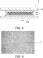
- FIG. 1 to FIG. 5 are schematic configuration diagrams schematically illustrating various examples of a configuration of an aluminum composite material according to an embodiment of the present invention.
- FIG. 6 shows a photograph representing a photographed surface of an aluminum fiber structure of an aluminum composite material according to the present embodiment.
- FIG. 7 shows a photograph representing a cut surface obtained by cutting the aluminum fiber structure shown in FIG. 6 .
- FIG. 8 shows a photograph representing a part of a cross section of the aluminum fiber structure shown in FIG. 7 in an enlarged manner.
- FIG. 9 schematically illustrates a method for producing an aluminum fiber structure of an aluminum composite material according to the present embodiment.
- Aluminum composite materials 1, 2, 3, 4, 5 are each a composite formed of an aluminum fiber structure 10 and a composite material formed of a material different from aluminum. Various examples of the aluminum composite materials 1, 2, 3, 4, 5 having such configurations will be described with reference to FIG. 1 to FIG. 5 .
- a resin 70 is fully impregnated into the aluminum fiber structure 10.
- a material of the resin 70 is not particularly limited, and examples thereof include epoxy, polyolefin, styrene-based polymers, polyether, polyurea, acrylic polymers, polyurethane, polyester, polyamide, polysiloxane, polysaccharide, polypeptide, polynucleotide, polyvinyl alcohol, polyacrylamide, and mixtures thereof.
- the resin 70 is fully impregnated into two aluminum fiber structures 10, and the aluminum fiber structures 10 are thus disposed at portions near the front side and the back side, respectively, of the resin 70.
- the aluminum fiber structures 10 do not protrude outward from the front surface and the back surface of the resin 70.
- the resin 70 is partially impregnated into the aluminum fiber structure 10.
- the resin 70 is partially impregnated into two aluminum fiber structures 10, and thus, the aluminum fiber structures 10 are disposed at portions near the front side and the back side, respectively, of the resin 70, and the aluminum fiber structures 10 protrude outward from the front surface and the back surface, respectively, of the resin 70.
- two aluminum fiber structures 10 are adhered by an adhesive layer 80 formed of an adhesive such as a metal paste other than aluminum, e.g. silver paste, copper paste, or nickel paste, silver solder, copper brazing, tin, or solder.
- an adhesive such as a metal paste other than aluminum, e.g. silver paste, copper paste, or nickel paste, silver solder, copper brazing, tin, or solder.
- a metal component 90 such as a copper plate is adhered to one surface of the aluminum fiber structure 10 by the adhesive layer 80 formed of an adhesive such as metal paste other than aluminum.
- the metal component 90 is adhered to one surface of the aluminum fiber structure 10 by the adhesive layer 80 formed of an adhesive such as metal paste other than aluminum, and an alumina plate 100 is adhered to the other surface of the aluminum fiber structure 10 by an adhesive layer 110 formed of an adhesive such as glass (for example, water glass, frit glass, glass paste).
- the aluminum fiber structure 10 As shown in FIG. 6 to FIG. 8 , in the aluminum fiber structure 10 of the present embodiment, aluminum fibers 20 are partially bound to each other, and an alumina layer 30 is formed on the surface of the aluminum fiber 20. Furthermore, as shown in FIG. 8 , a plurality of alumina protrusions 40 each having a height larger than the thickness of the alumina layer 30 are formed on the surfaces of the aluminum fibers 20 or the alumina layers 30.
- reference numeral 22 represents a portion of the surface of the aluminum fiber 20 in which neither the alumina layer 30 nor the protrusion 40 is formed.
- the coefficient of linear thermal expansion is partially non-uniform, so that the coefficient of linear thermal expansion can be reduced as a whole.
- the aluminum fiber 20 has a length ranging from 0.2 to 15 mm and a diameter ranging from 0.01 to 0.100 mm.
- the length of the aluminum fiber 20 can be actually measured and confirmed by observing a photograph with use of an SEM, an optical microscope, or the like.
- the alumina layer 30 is formed by oxidizing the aluminum fiber 20 in an air atmosphere. In general, the alumina layer 30 is uniformly formed on the surface of the aluminum fiber 20.
- the thickness of the alumina layer 30 having such a configuration ranges from 10 nm to 10 ⁇ m, preferably ranges from 100 nm to 7 ⁇ m, and more preferably ranges from 1 ⁇ m to 5 ⁇ m.
- the protrusions 40 are formed by an eluted substance from the aluminum fibers 20 by sintering the aluminum fibers 20 at 700°C or higher.
- a method for producing the aluminum fiber structure 10 by sintering the aluminum fibers 20 will be described below. In a case where a temperature at which the aluminum fibers 20 are sintered is lower than 700°C, a sufficient amount of alumina is not eluted from the aluminum fibers 20, and the protrusion 40 having a sufficient height cannot be obtained.
- a height of the protrusion 40 at the surface of the aluminum fiber 20 or the alumina layer 30 is larger than the thickness of the alumina layer 30.
- the height of the protrusion 40 at the surface of the aluminum fiber 20 or the alumina layer 30 ranges from 10 nm to 10 ⁇ m, preferably ranges from 100 nm to 7 ⁇ m, and more preferably ranges from 1 ⁇ m to 5 ⁇ m.
- strength for adhering the aluminum fiber 20 and the protrusion 40 becomes high.
- the height of the protrusion 40 at the surface of the aluminum fiber 20 or the alumina layer 30 is excessively small, specifically, in a case where the height of the protrusion 40 is less than 10 nm, a difference between the thickness of the alumina layer 30 and the height of the protrusion 40 does not become large, and a problem arises that the aluminum fiber structure 10 having a partially non-uniform coefficient of linear thermal expansion cannot be formed.
- the height of the protrusion 40 at the surface of the aluminum fiber 20 or the alumina layer 30 is excessively large, specifically, in a case where the height of the protrusion 40 is larger than 10 ⁇ m, a problem arises that a large gap may be formed between the aluminum fibers 20.
- a coverage at a portion covered by the protrusion 40 on the surface of the aluminum fiber 20 is preferably 20% or more and more preferably 40% or more in total.
- the surface of the aluminum fiber 20 is almost entirely covered by the alumina layer 30, and the protrusion 40 is formed on a part of the alumina layer 30.
- a coverage at a portion covered by the protrusion 40 on the surface of the aluminum fiber 20 can be calculated by dividing a length of the alumina layer 30 at a portion covered by the protrusion 40 (specifically, a portion from a peak rise starting point of the protrusion 40 to a descending end point thereof), by the entire length of the alumina layer 30, on the cross-section of the aluminum fiber structure 10.
- the coverage of the protrusions 40 at the surfaces of the aluminum fibers 20 is less than 20%, a proportion of the protrusions 40 in the aluminum fiber structure 10 is relatively small, and a problem arises that the coefficient of linear thermal expansion of the aluminum fiber structure 10 is not reduced.
- At least a part of the plurality of the protrusions 40 are each in contact with the alumina layers 30 of a plurality of the aluminum fibers 20 in a straddling manner.
- the aluminum fibers 20 are connected with each other by the protrusion 40, so that the aluminum fibers 20 are unlikely to move relative to each other, and thus, the coefficient of linear thermal expansion of the aluminum fiber structure 10 can be further reduced.
- the aluminum fiber structure 10 and a composite material for example, the resin 70, the adhesive layer 80, the adhesive layer 110 as described above
- the composite material that has entered a gap of the aluminum fiber structure 10 comes into contact with the protrusion 40.
- a space factor of the aluminum fibers 20 in the aluminum fiber structure 10 ranges from 20% to 90%.
- Such a space factor of the aluminum fibers 20 can be obtained by calculating a proportion of an area occupied by the aluminum fibers 20 to an area inside the outer edge of the aluminum fiber structure 10, on the cut surface obtained by cutting the aluminum fiber structure 10.
- the aluminum fiber structure 10 can have both a light weight and strength. That is, in a case where the space factor of the aluminum fibers 20 in the aluminum fiber structure 10 is less than 20%, sufficient strength cannot be obtained.
- the space factor of the aluminum fibers 20 in the aluminum fiber structure 10 is more than 90%, a problem arises that the weight cannot be reduced.
- the space factor of the aluminum fibers 20 in the aluminum fiber structure 10 is 20% or more, an amount of the aluminum fibers 20 is sufficient and appropriate uniformity can thus be obtained.
- the space factor of the aluminum fibers 20 in the aluminum fiber structure 10 is 90% or less, flexibility can be obtained as desired in addition to appropriate uniformity being obtained.
- a plasma-resistant layer may be formed on the surfaces of the alumina layer 30 and the protrusion 40.
- the plasma-resistant layer may include metal oxide or aluminum nitride.
- the metal oxide includes, for example, at least one of zirconium oxide, yttrium oxide, magnesium oxide, zinc oxide, sapphire, and quartz glass.
- a composite material formed of the aluminum fiber structure 10 and the plasma-resistant layer can be provided, and the composite material has excellent plasma resistance.
- Such a composite material formed of the aluminum fiber structure 10 and the plasma-resistant layer can be produced by applying glaze containing zirconia, yttria, or the like to the alumina layer 30 and the protrusion 40 of the aluminum fiber structure 10 and thereafter heating the obtained product at a high temperature.
- the aluminum fibers 20 are formed into a sheet-like shape in a molding container 50, and pressed. Thus, the aluminum fibers 20 can be brought into close contact with each other. Furthermore, as shown in FIG. 9(b) , the aluminum fibers 20 are heated at 700°C or higher in sintering equipment 60 and thus sintered. Thus, the aluminum fiber structure 10 is formed.
- a method for heating the aluminum fibers 20 is, but is not limited to, a method for heating the surfaces of the aluminum fibers 20 by hot air or the like. As a method for heating the aluminum fibers 20, an electric heating method may be used.
- the aluminum fibers 20 are sintered at 700°C or higher, alumina is eluted from the aluminum fibers 20, and the eluted alumina is solidified at ordinary temperature to form the protrusions 40.
- the aluminum fiber structure 10 is placed in an air atmosphere, and thus, the aluminum fibers 20 are oxidized to form the alumina layers 30.
- the aluminum fibers 20 are partially bound to each other, and the alumina layer 30 is formed on the surface of the aluminum fiber 20.
- the plurality of alumina protrusions 40 each having the height larger than the thickness of the alumina layer 30 are formed on the surfaces of the aluminum fibers 20 or the alumina layers 30.
- a portion of the aluminum fiber structure 10 in which the alumina layers 30 are formed is likely to expand or contract due to temperature change whereas a portion thereof in which the plurality of alumina protrusions 40 are formed is unlikely to expand or contract due to temperature change.
- the coefficient of linear thermal expansion is partially non-uniform, so that the coefficient of linear thermal expansion can be reduced as a whole.
- the alumina protrusions 40 and at least a part of the composite material are in contact with each other. Even in a case where a temperature in a surrounding environment greatly changes, the aluminum fiber structure 10 and the composite material are unlikely to separate from each other. More specifically, the composite material that has entered a gap of the aluminum fiber structure 10 is caught by the protrusion 40 of the aluminum fiber structure 10. Therefore, even in a case where a composite material that does not easily adhere to aluminum is used, the aluminum fiber structure 10 can be firmly adhered to the composite material.
- the resin 70 that has entered a gap of the aluminum fiber structure 10 is caught by the protrusion 40 of the aluminum fiber structure 10. Therefore, even in a case where the resin 70 is a material that does not easily adhere to aluminum, the aluminum fiber structure 10 can be firmly adhered to the resin 70.
- the adhesive that has entered a gap of the aluminum fiber structure 10 is caught by the protrusion 40 of the aluminum fiber structure 10, so that the aluminum fiber structure 10 can be firmly adhered to the adhesive layer 80.
- the two aluminum fiber structures 10 are unlikely to separate from each other.
- the aluminum fiber structure 10 is unlikely to separate from the metal component 90 such as a copper plate. Also in a case where adhesion between the metal component 90 and the adhesive layer 80 is weak, since the aluminum fiber structure 10 has a low coefficient of linear thermal expansion, the aluminum fiber structure 10 is unlikely to separate from the metal component 90 even if the metal component 90 expands.
- the adhesive that has entered a gap of the aluminum fiber structure 10 is caught by the protrusion 40 of the aluminum fiber structure 10, so that the aluminum fiber structure 10 can be firmly adhered to each of the adhesive layers 80 and 110.
- the aluminum fiber structure 10 is unlikely to separate from each of the metal component 90 and the alumina plate 100.
- the aluminum fiber structure 10 has a low coefficient of linear thermal expansion, separation between the metal component 90 and the aluminum fiber structure 10 and separation between the alumina plate 100 and the aluminum fiber structure 10 are unlikely to occur in the entirety of the aluminum composite material 5.
- An aluminum fiber structure was produced in the following procedure. Firstly, a plurality of aluminum fibers which were formed of A1070 as a material, had a fiber diameter of 50 ⁇ m, and had an average length of 2 mm were formed into a sheet-like shape. Thereafter, the aluminum fibers were heated at 700°C in sintering equipment and thus sintered. Thus, an aluminum fiber structure was produced.
- Aluminum fiber structures were each produced in the same method as for Example 1 except that aluminum fibers were heated in sintering equipment at 750°C, 800°C, and 850°C, respectively, and thus sintered.
- a cut surface obtained by cutting each of the produced aluminum fiber structures of Examples 2 to 4 was observed by a microscope, it was found that an alumina layer was formed on the surface of the aluminum fiber, and a plurality of alumina protrusions each having a height larger than the thickness of the alumina layer were formed on the surfaces of the alumina layers or the aluminum fibers.
- the physical property values of the produced aluminum fiber structures of Examples 2 to 4 are as indicated below in Table 1.
- Aluminum fiber structures were each produced in the same method as for Example 1 except that the fiber diameter and the average length of the plurality of aluminum fibers were as indicated in Table 1, and the aluminum fibers were heated in sintering equipment at a temperature (800°C or 900°C) indicated in Table 1 and thus sintered.
- a cut surface obtained by cutting each of the produced aluminum fiber structures of Examples 5 to 8 was observed by a microscope, it was found that an alumina layer was formed on the surface of the aluminum fiber, and a plurality of alumina protrusions each having a height larger than the thickness of the alumina layer were formed on the surfaces of the alumina layers or the aluminum fibers.
- the physical property values of the produced aluminum fiber structures of Examples 5 to 8 are as indicated below in Table 1.
- Example 1 aluminum fibers were formed into a sheet-like shape, and the aluminum fibers were thereafter heated at 900°C in sintering equipment and thus sintered. Glaze containing yttria was applied to the surface of the aluminum fiber structure, and the obtained product was thereafter heated at a high temperature.
- Glaze containing yttria was applied to the surface of the aluminum fiber structure, and the obtained product was thereafter heated at a high temperature.
- a cut surface obtained by cutting the aluminum fiber structure thus produced was observed by a microscope, it was found that an alumina layer was formed on the surface of the aluminum fiber, and a plurality of alumina protrusions each having a height larger than the thickness of the alumina layer were formed on the surfaces of the alumina layers or the aluminum fibers.
- a plasma-resistant layer containing yttrium oxide was formed on the surfaces of the alumina layers and the protrusions.
- the physical property values of the produced aluminum fiber structure of Example 9 are as indicated below in Table 1.
- Example 1 aluminum fibers were formed into a sheet-like shape, and the aluminum fibers were thereafter heated at 900°C in sintering equipment and thus sintered. Glaze containing zirconia was applied to the surface of the aluminum fiber structure, and the obtained product was thereafter heated at a high temperature.
- Glaze containing zirconia was applied to the surface of the aluminum fiber structure, and the obtained product was thereafter heated at a high temperature.
- a cut surface obtained by cutting the aluminum fiber structure thus produced was observed by a microscope, it was found that the alumina layer was formed on the surface of the aluminum fiber, and a plurality of alumina protrusions each having a height larger than the thickness of the alumina layer were formed on the surfaces of the alumina layers or the aluminum fibers.
- a plasma-resistant layer containing zirconium oxide was formed on the surfaces of the alumina layers and the protrusions.
- the physical property values of the produced aluminum fiber structure of Example 10 are as indicated below in Table 1.
- Aluminum fiber structures of Comparative examples 1 to 2 were produced in the same method as for Example 1 except that aluminum fibers were heated in sintering equipment at 680°C and 600°C, respectively, and thus sintered. When a cut surface obtained by cutting each of the produced aluminum fiber structures of Comparative examples 1 to 2 was observed by a microscope, it was found that an alumina layer was formed on the surface of the aluminum fiber, but no alumina protrusions were formed on the surfaces of the alumina layers or the aluminum fibers.
- the physical property values of the produced aluminum fiber structures of Comparative examples 1 to 2 are as indicated below in Table 1.
- the coefficient of linear thermal expansion at 40°C was measured for each of the aluminum fiber structures of Examples 1 to 10 and Comparative examples 1 to 3.
- the examination results are indicated below in Table 1 and Table 2.
- the coverage refers to a coverage of the protrusion portions at the surfaces of the aluminum fibers on the cross-section obtained by cutting the aluminum fiber structure, and was calculated by dividing a length of the alumina layer at a portion (specifically, a portion from a peak rise starting point of the protrusion to a descending end point thereof) covered by the protrusion, by the entire length of the alumina layer, on the cross-section of the aluminum fiber structure.
- the coverage was 0%, and this means that no alumina protrusions were formed.
- the space factor refers to a space factor of the aluminum fibers in the aluminum fiber structure, and was defined as a proportion of an area occupied by the aluminum fibers to an area inside the outer edge of the aluminum fiber structure, on the cut surface obtained by cutting the aluminum fiber structure.
- the coefficient of linear thermal expansion was 22.0 or less in each of the aluminum fiber structures of Examples 1 to 10 whereas the coefficient of linear thermal expansion was more than 23.0 in each of the aluminum fiber structures of Comparative examples 1 to 3. According to the above-described results, it was found that, in a case where the aluminum fibers were heated at 700°C or higher in sintering equipment and thus sintered, the coefficient of linear thermal expansion of the aluminum fiber structure was able to be reduced.
- An aluminum composite material as shown in FIG. 2 was produced by adhering two aluminum fiber structures by a resin.
- the resin was partially impregnated into the aluminum fiber structure.
- the resin was partially impregnated into the two aluminum fiber structures, and thus, the aluminum fiber structures were disposed at portions near the front side and the back side, respectively, of the resin, and the aluminum fiber structures protruded outward from the front surface and the back surface, respectively, of the resin.
- the aluminum fiber structure the aluminum fiber structure of Example 1 was used, and each aluminum fiber structure had a thickness of 3.0 mm and a space factor of 75%.
- epoxy resin was used, and the adhesive layer had a thickness of 125 ⁇ m.
- An aluminum composite material as shown in FIG. 3 was produced by adhering two aluminum fiber structures by an adhesive layer formed of a silver paste adhesive.
- the aluminum fiber structure the aluminum fiber structure of Example 1 was used, and each aluminum fiber structure had a thickness of 3.0 mm and a space factor of 75%.
- the adhesive layer formed of the silver paste adhesive had a thickness of 12 ⁇ m.
- An aluminum composite material as shown in FIG. 4 was produced by adhering a copper plate to one surface of an aluminum fiber structure by an adhesive layer formed of a copper paste adhesive.
- the aluminum fiber structure the aluminum fiber structure of Example 3 was used, and the aluminum fiber structure had a thickness of 1.0 mm and a space factor of 72%.
- the adhesive layer formed of the copper paste adhesive had a thickness of 48 ⁇ m.
- the copper plate a copper plate which was formed of C1100 as a material, and had a thickness of 5.0 mm and a space factor of 100% was used.
- An aluminum composite material as shown in FIG. 5 was produced by adhering a copper plate to one surface of an aluminum fiber structure by an adhesive layer formed of a copper paste adhesive and adhering an alumina plate to the other surface of the aluminum fiber structure by an adhesive layer formed of a glass paste adhesive.
- the aluminum fiber structure the aluminum fiber structure of Example 3 was used, and the aluminum fiber structure had a thickness of 1.0 mm and a space factor of 72%.
- the adhesive layer formed of the copper paste adhesive had a thickness of 48 ⁇ m.
- As the copper plate a copper plate which was formed of C1100 as a material, and which had a thickness of 0.5 mm and a space factor of 100% was used.
- the adhesive layer formed of the glass paste adhesive had a thickness of 27 ⁇ m.
- the alumina plate an alumina plate having a thickness of 1.0 mm and a space factor of 100% was used.
- An aluminum composite material as shown in FIG. 5 was produced by adhering a copper plate to one surface of an aluminum plate instead of the aluminum fiber structure as in Example 14 by an adhesive layer formed of a copper paste adhesive, and adhering an alumina plate to the other surface of the aluminum plate by an adhesive layer formed of a glass paste adhesive.
- As the aluminum plate an aluminum plate having a thickness of 1.0 mm and a space factor of 100% was used.
- the adhesive layer formed of the copper paste adhesive had a thickness of 43 ⁇ m.
- As the copper plate a copper plate which was formed of C1100 as a material, and which had a thickness of 0.5 mm and a space factor of 100% was used.
- the adhesive layer formed of the glass paste adhesive had a thickness of 34 ⁇ m.
- As the alumina plate an alumina plate having a thickness of 1.0 mm and a space factor of 100% was used.
- An alumina composite material was produced by adhering a copper plate to one surface of an alumina plate by an adhesive layer formed of a glass paste adhesive.
- alumina plate an alumina plate having a thickness of 1.0 mm and a space factor of 100% was used.
- the adhesive layer formed of the glass paste adhesive had a thickness of 32 ⁇ m.
- the copper plate a copper plate which was formed of C1100 as a material, and which had a thickness of 0.5 mm and a space factor of 100% was used.
- Adhesiveness and adhesion strength were evaluated for the aluminum composite materials and the alumina composite material according to Examples 11 to 14 and Comparative examples 4 to 5.
- the aluminum composite materials and the alumina composite material according to Examples 11 to 14 and Comparative examples 4 to 5 were subjected to a heat shock test (the number of times of cycling between -40°C and 120°C was 500, and a retention time was 30 minutes in total), and whether or not separation occurred was visually checked. A case where no separation occurred was evaluated as "good", and a case where separation partially occurred or floating occurred in the composite member was evaluated as "poor".
- the adhesiveness and the adhesion strength were good. Specifically, separation was unlikely to occur, and even temperature change in a surrounding environment was unlikely to cause change in the adhesion strength. Meanwhile, in a case where the aluminum plate or the alumina plate instead of the aluminum fiber structure was used for the aluminum composite material, the adhesiveness and the adhesion strength were poor as compared with a case where the aluminum fiber structure was used. Thus, in a case where the aluminum fiber structure was used for the aluminum composite material, even when a temperature in a surrounding environment greatly changed, separation between the aluminum fiber structure and the composite material was unlikely to occur.
Landscapes
- Engineering & Computer Science (AREA)
- Chemical & Material Sciences (AREA)
- Mechanical Engineering (AREA)
- Materials Engineering (AREA)
- Organic Chemistry (AREA)
- Metallurgy (AREA)
- Manufacturing & Machinery (AREA)
- Textile Engineering (AREA)
- Physics & Mathematics (AREA)
- Thermal Sciences (AREA)
- General Engineering & Computer Science (AREA)
- Inorganic Chemistry (AREA)
- Composite Materials (AREA)
- Life Sciences & Earth Sciences (AREA)
- Nanotechnology (AREA)
- Sustainable Development (AREA)
- Chemical Kinetics & Catalysis (AREA)
- General Chemical & Material Sciences (AREA)
- Laminated Bodies (AREA)
- Manufacture Of Alloys Or Alloy Compounds (AREA)
- Inorganic Fibers (AREA)
Abstract
Description
- The present invention relates to an aluminum fiber structure and an aluminum composite material.
- To date, a metal fiber structure formed from metal fibers has been used as a medium for transmitting heat in a heat exchanger in some cases.
Japanese Laid-Open Patent Publication No. 2011-007365 JP2011-007365A - The aluminum fiber structure disclosed in
Japanese Laid-Open Patent Publication No. 2011-007365 - The aluminum fiber structure disclosed in
Japanese Laid-Open Patent Publication No. 2011-007365 - The present invention has been made in view of such circumstances, and an object of the present invention is to provide an aluminum fiber structure having a low coefficient of linear thermal expansion, and an aluminum composite material in which the aluminum fiber structure and a composite material are unlikely to separate from each other even in a case where a temperature in a surrounding environment has greatly changed.
- An aluminum fiber structure of the present invention includes
- aluminum fibers partially bound to each other, in which
- alumina layers are formed on surfaces of the aluminum fibers, and
- a plurality of alumina protrusions each having a height larger than a thickness of each alumina layer are formed on surfaces of the aluminum fibers or the alumina layers.
- An aluminum composite material of the present invention includes
- the above-described aluminum fiber structure and a composite material which form a composite, in which
- the alumina protrusions and at least a part of the composite material are in contact with each other.
-
-
FIG. 1 is a schematic configuration diagram schematically illustrating a first example of a configuration of an aluminum composite material according to an embodiment of the present invention. -
FIG. 2 is a schematic configuration diagram schematically illustrating a second example of a configuration of an aluminum composite material according to an embodiment of the present invention. -
FIG. 3 is a schematic configuration diagram schematically illustrating a third example of a configuration of an aluminum composite material according to an embodiment of the present invention. -
FIG. 4 is a schematic configuration diagram schematically illustrating a fourth example of a configuration of an aluminum composite material according to an embodiment of the present invention. -
FIG. 5 is a schematic configuration diagram schematically illustrating a fifth example of a configuration of an aluminum composite material according to an embodiment of the present invention. -
FIG. 6 shows a photograph representing a photographed surface of an aluminum fiber structure of an aluminum composite material according to an embodiment of the present invention. -
FIG. 7 shows a photograph representing a cut surface obtained by cutting the aluminum fiber structure shown inFIG. 6 . -
FIG. 8 shows a photograph representing a part of a cross section of the aluminum fiber structure shown inFIG. 7 in an enlarged manner. -
FIG. 9 schematically illustrates a method for producing an aluminum fiber structure of an aluminum composite material according to an embodiment of the present invention. - Embodiments of the present invention will be described below with reference to the drawings.
FIG. 1 to FIG. 5 are schematic configuration diagrams schematically illustrating various examples of a configuration of an aluminum composite material according to an embodiment of the present invention.FIG. 6 shows a photograph representing a photographed surface of an aluminum fiber structure of an aluminum composite material according to the present embodiment.FIG. 7 shows a photograph representing a cut surface obtained by cutting the aluminum fiber structure shown inFIG. 6 .FIG. 8 shows a photograph representing a part of a cross section of the aluminum fiber structure shown inFIG. 7 in an enlarged manner.FIG. 9 schematically illustrates a method for producing an aluminum fiber structure of an aluminum composite material according to the present embodiment. - Aluminum
composite materials aluminum fiber structure 10 and a composite material formed of a material different from aluminum. Various examples of the aluminumcomposite materials FIG. 1 to FIG. 5 . - As shown in
FIG. 1 , in the aluminumcomposite material 1 as a first example, aresin 70 is fully impregnated into thealuminum fiber structure 10. A material of theresin 70 is not particularly limited, and examples thereof include epoxy, polyolefin, styrene-based polymers, polyether, polyurea, acrylic polymers, polyurethane, polyester, polyamide, polysiloxane, polysaccharide, polypeptide, polynucleotide, polyvinyl alcohol, polyacrylamide, and mixtures thereof. Specifically, theresin 70 is fully impregnated into twoaluminum fiber structures 10, and thealuminum fiber structures 10 are thus disposed at portions near the front side and the back side, respectively, of theresin 70. Thealuminum fiber structures 10 do not protrude outward from the front surface and the back surface of theresin 70. - As shown in
FIG. 2 , in the aluminumcomposite material 2 as a second example, theresin 70 is partially impregnated into thealuminum fiber structure 10. Specifically, theresin 70 is partially impregnated into twoaluminum fiber structures 10, and thus, thealuminum fiber structures 10 are disposed at portions near the front side and the back side, respectively, of theresin 70, and thealuminum fiber structures 10 protrude outward from the front surface and the back surface, respectively, of theresin 70. - As shown in
FIG. 3 , in the aluminumcomposite material 3 as a third example, twoaluminum fiber structures 10 are adhered by anadhesive layer 80 formed of an adhesive such as a metal paste other than aluminum, e.g. silver paste, copper paste, or nickel paste, silver solder, copper brazing, tin, or solder. - As shown in
FIG. 4 , in the aluminumcomposite material 4 as a fourth example, ametal component 90 such as a copper plate is adhered to one surface of thealuminum fiber structure 10 by theadhesive layer 80 formed of an adhesive such as metal paste other than aluminum. - As shown in
FIG. 5 , in the aluminumcomposite material 5 as a fifth example, themetal component 90 is adhered to one surface of thealuminum fiber structure 10 by theadhesive layer 80 formed of an adhesive such as metal paste other than aluminum, and analumina plate 100 is adhered to the other surface of thealuminum fiber structure 10 by anadhesive layer 110 formed of an adhesive such as glass (for example, water glass, frit glass, glass paste). - Next, a configuration of the
aluminum fiber structure 10 will be described. As shown inFIG. 6 to FIG. 8 , in thealuminum fiber structure 10 of the present embodiment,aluminum fibers 20 are partially bound to each other, and analumina layer 30 is formed on the surface of thealuminum fiber 20. Furthermore, as shown inFIG. 8 , a plurality ofalumina protrusions 40 each having a height larger than the thickness of thealumina layer 30 are formed on the surfaces of thealuminum fibers 20 or thealumina layers 30. InFIG. 8 ,reference numeral 22 represents a portion of the surface of thealuminum fiber 20 in which neither thealumina layer 30 nor theprotrusion 40 is formed. - In the
aluminum fiber structure 10 having such a configuration, a portion of thealuminum fiber structure 10 in which thealumina layers 30 are formed is likely to expand or contract due to temperature change whereas a portion thereof in which the plurality ofalumina protrusions 40 are formed is unlikely to expand or contract due to temperature change. Thus, in the entirety of thealuminum fiber structure 10, the coefficient of linear thermal expansion is partially non-uniform, so that the coefficient of linear thermal expansion can be reduced as a whole. - The
aluminum fiber 20 has a length ranging from 0.2 to 15 mm and a diameter ranging from 0.01 to 0.100 mm. The length of thealuminum fiber 20 can be actually measured and confirmed by observing a photograph with use of an SEM, an optical microscope, or the like. - The
alumina layer 30 is formed by oxidizing thealuminum fiber 20 in an air atmosphere. In general, thealumina layer 30 is uniformly formed on the surface of thealuminum fiber 20. The thickness of thealumina layer 30 having such a configuration ranges from 10 nm to 10 µm, preferably ranges from 100 nm to 7 µm, and more preferably ranges from 1 µm to 5 µm. - The
protrusions 40 are formed by an eluted substance from thealuminum fibers 20 by sintering thealuminum fibers 20 at 700°C or higher. A method for producing thealuminum fiber structure 10 by sintering thealuminum fibers 20 will be described below. In a case where a temperature at which thealuminum fibers 20 are sintered is lower than 700°C, a sufficient amount of alumina is not eluted from thealuminum fibers 20, and theprotrusion 40 having a sufficient height cannot be obtained. - As described above, a height of the
protrusion 40 at the surface of thealuminum fiber 20 or thealumina layer 30 is larger than the thickness of thealumina layer 30. Specifically, the height of theprotrusion 40 at the surface of thealuminum fiber 20 or thealumina layer 30 ranges from 10 nm to 10 µm, preferably ranges from 100 nm to 7 µm, and more preferably ranges from 1 µm to 5 µm. Thus, strength for adhering thealuminum fiber 20 and theprotrusion 40 becomes high. In a case where the height of theprotrusion 40 at the surface of thealuminum fiber 20 or thealumina layer 30 is excessively small, specifically, in a case where the height of theprotrusion 40 is less than 10 nm, a difference between the thickness of thealumina layer 30 and the height of theprotrusion 40 does not become large, and a problem arises that thealuminum fiber structure 10 having a partially non-uniform coefficient of linear thermal expansion cannot be formed. In a case where the height of theprotrusion 40 at the surface of thealuminum fiber 20 or thealumina layer 30 is excessively large, specifically, in a case where the height of theprotrusion 40 is larger than 10 µm, a problem arises that a large gap may be formed between thealuminum fibers 20. - On the cross-section of the
aluminum fiber structure 10 as shown inFIG. 7 and FIG. 8 , a coverage at a portion covered by theprotrusion 40 on the surface of thealuminum fiber 20 is preferably 20% or more and more preferably 40% or more in total. The surface of thealuminum fiber 20 is almost entirely covered by thealumina layer 30, and theprotrusion 40 is formed on a part of thealumina layer 30. A coverage at a portion covered by theprotrusion 40 on the surface of thealuminum fiber 20 can be calculated by dividing a length of thealumina layer 30 at a portion covered by the protrusion 40 (specifically, a portion from a peak rise starting point of theprotrusion 40 to a descending end point thereof), by the entire length of thealumina layer 30, on the cross-section of thealuminum fiber structure 10. In a case where the coverage of theprotrusions 40 at the surfaces of thealuminum fibers 20 is less than 20%, a proportion of theprotrusions 40 in thealuminum fiber structure 10 is relatively small, and a problem arises that the coefficient of linear thermal expansion of thealuminum fiber structure 10 is not reduced. - At least a part of the plurality of the
protrusions 40 are each in contact with the alumina layers 30 of a plurality of thealuminum fibers 20 in a straddling manner. In this case, thealuminum fibers 20 are connected with each other by theprotrusion 40, so that thealuminum fibers 20 are unlikely to move relative to each other, and thus, the coefficient of linear thermal expansion of thealuminum fiber structure 10 can be further reduced. Furthermore, when thealuminum fiber structure 10 and a composite material (for example, theresin 70, theadhesive layer 80, theadhesive layer 110 as described above) form a composite, the composite material that has entered a gap of thealuminum fiber structure 10 comes into contact with theprotrusion 40. - Furthermore, in the present embodiment, a space factor of the
aluminum fibers 20 in thealuminum fiber structure 10 ranges from 20% to 90%. Such a space factor of thealuminum fibers 20 can be obtained by calculating a proportion of an area occupied by thealuminum fibers 20 to an area inside the outer edge of thealuminum fiber structure 10, on the cut surface obtained by cutting thealuminum fiber structure 10. In a case where the space factor of thealuminum fibers 20 in thealuminum fiber structure 10 ranges from 20% to 90%, thealuminum fiber structure 10 can have both a light weight and strength. That is, in a case where the space factor of thealuminum fibers 20 in thealuminum fiber structure 10 is less than 20%, sufficient strength cannot be obtained. Meanwhile, in a case where the space factor of thealuminum fibers 20 in thealuminum fiber structure 10 is more than 90%, a problem arises that the weight cannot be reduced. In a case where the space factor of thealuminum fibers 20 in thealuminum fiber structure 10 is 20% or more, an amount of thealuminum fibers 20 is sufficient and appropriate uniformity can thus be obtained. In a case where the space factor of thealuminum fibers 20 in thealuminum fiber structure 10 is 90% or less, flexibility can be obtained as desired in addition to appropriate uniformity being obtained. - Furthermore, in the
aluminum fiber structure 10 of the present embodiment, a plasma-resistant layer may be formed on the surfaces of thealumina layer 30 and theprotrusion 40. In the present embodiment, the plasma-resistant layer may include metal oxide or aluminum nitride. The metal oxide includes, for example, at least one of zirconium oxide, yttrium oxide, magnesium oxide, zinc oxide, sapphire, and quartz glass. In this case, a composite material formed of thealuminum fiber structure 10 and the plasma-resistant layer can be provided, and the composite material has excellent plasma resistance. Such a composite material formed of thealuminum fiber structure 10 and the plasma-resistant layer can be produced by applying glaze containing zirconia, yttria, or the like to thealumina layer 30 and theprotrusion 40 of thealuminum fiber structure 10 and thereafter heating the obtained product at a high temperature. - As shown in
FIG. 9(a) , thealuminum fibers 20 are formed into a sheet-like shape in amolding container 50, and pressed. Thus, thealuminum fibers 20 can be brought into close contact with each other. Furthermore, as shown inFIG. 9(b) , thealuminum fibers 20 are heated at 700°C or higher insintering equipment 60 and thus sintered. Thus, thealuminum fiber structure 10 is formed. A method for heating thealuminum fibers 20 is, but is not limited to, a method for heating the surfaces of thealuminum fibers 20 by hot air or the like. As a method for heating thealuminum fibers 20, an electric heating method may be used. As described above, in a case where thealuminum fibers 20 are sintered at 700°C or higher, alumina is eluted from thealuminum fibers 20, and the eluted alumina is solidified at ordinary temperature to form theprotrusions 40. Thealuminum fiber structure 10 is placed in an air atmosphere, and thus, thealuminum fibers 20 are oxidized to form the alumina layers 30. - In summary, in the
aluminum fiber structure 10 of the present embodiment, thealuminum fibers 20 are partially bound to each other, and thealumina layer 30 is formed on the surface of thealuminum fiber 20. The plurality ofalumina protrusions 40 each having the height larger than the thickness of thealumina layer 30 are formed on the surfaces of thealuminum fibers 20 or the alumina layers 30. In thealuminum fiber structure 10 having such a configuration, a portion of thealuminum fiber structure 10 in which the alumina layers 30 are formed is likely to expand or contract due to temperature change whereas a portion thereof in which the plurality ofalumina protrusions 40 are formed is unlikely to expand or contract due to temperature change. Thus, in the entirety of thealuminum fiber structure 10, the coefficient of linear thermal expansion is partially non-uniform, so that the coefficient of linear thermal expansion can be reduced as a whole. - In the
aluminum composite materials aluminum fiber structure 10 having such a configuration, and a composite material formed of the composite material (for example, theresin 70, theadhesive layer 80, the adhesive layer 110) different from aluminum form a composite, thealumina protrusions 40 and at least a part of the composite material are in contact with each other. Even in a case where a temperature in a surrounding environment greatly changes, thealuminum fiber structure 10 and the composite material are unlikely to separate from each other. More specifically, the composite material that has entered a gap of thealuminum fiber structure 10 is caught by theprotrusion 40 of thealuminum fiber structure 10. Therefore, even in a case where a composite material that does not easily adhere to aluminum is used, thealuminum fiber structure 10 can be firmly adhered to the composite material. - For example, in the
aluminum composite materials 1 as the first and the second examples, theresin 70 that has entered a gap of thealuminum fiber structure 10 is caught by theprotrusion 40 of thealuminum fiber structure 10. Therefore, even in a case where theresin 70 is a material that does not easily adhere to aluminum, thealuminum fiber structure 10 can be firmly adhered to theresin 70. - In the
aluminum composite materials aluminum fiber structure 10 is caught by theprotrusion 40 of thealuminum fiber structure 10, so that thealuminum fiber structure 10 can be firmly adhered to theadhesive layer 80. Thus, in thealuminum composite material 3 as the third example, the twoaluminum fiber structures 10 are unlikely to separate from each other. In thealuminum composite material 4 as the fourth example, thealuminum fiber structure 10 is unlikely to separate from themetal component 90 such as a copper plate. Also in a case where adhesion between themetal component 90 and theadhesive layer 80 is weak, since thealuminum fiber structure 10 has a low coefficient of linear thermal expansion, thealuminum fiber structure 10 is unlikely to separate from themetal component 90 even if themetal component 90 expands. - In the
aluminum composite material 5 as the fifth example, the adhesive that has entered a gap of thealuminum fiber structure 10 is caught by theprotrusion 40 of thealuminum fiber structure 10, so that thealuminum fiber structure 10 can be firmly adhered to each of theadhesive layers aluminum fiber structure 10 is unlikely to separate from each of themetal component 90 and thealumina plate 100. In this case, even in a case where there is a difference between the coefficient of linear thermal expansion of themetal component 90 and that of thealumina plate 100, since thealuminum fiber structure 10 has a low coefficient of linear thermal expansion, separation between themetal component 90 and thealuminum fiber structure 10 and separation between thealumina plate 100 and thealuminum fiber structure 10 are unlikely to occur in the entirety of thealuminum composite material 5. - The present invention will be described below in more detail by means of examples and comparative examples.
- An aluminum fiber structure was produced in the following procedure. Firstly, a plurality of aluminum fibers which were formed of A1070 as a material, had a fiber diameter of 50 µm, and had an average length of 2 mm were formed into a sheet-like shape. Thereafter, the aluminum fibers were heated at 700°C in sintering equipment and thus sintered. Thus, an aluminum fiber structure was produced.
- When a cut surface obtained by cutting the produced aluminum fiber structure was observed by a microscope, it was found that an alumina layer was formed on the surface of the aluminum fiber, and a plurality of alumina protrusions each having a height larger than the thickness of the alumina layer were formed on the surfaces of the alumina layers or the aluminum fibers. On the cross-section of the aluminum fiber structure, a coverage of the total of the alumina layers and the protrusions on the surfaces of the aluminum fibers was 24%, and a space factor of the aluminum fibers in the aluminum fiber structure was 75%. The physical property values of the aluminum fiber structure having such a configuration are as indicated below in Table 1.
- Aluminum fiber structures were each produced in the same method as for Example 1 except that aluminum fibers were heated in sintering equipment at 750°C, 800°C, and 850°C, respectively, and thus sintered. When a cut surface obtained by cutting each of the produced aluminum fiber structures of Examples 2 to 4 was observed by a microscope, it was found that an alumina layer was formed on the surface of the aluminum fiber, and a plurality of alumina protrusions each having a height larger than the thickness of the alumina layer were formed on the surfaces of the alumina layers or the aluminum fibers. The physical property values of the produced aluminum fiber structures of Examples 2 to 4 are as indicated below in Table 1.
- Aluminum fiber structures were each produced in the same method as for Example 1 except that the fiber diameter and the average length of the plurality of aluminum fibers were as indicated in Table 1, and the aluminum fibers were heated in sintering equipment at a temperature (800°C or 900°C) indicated in Table 1 and thus sintered. When a cut surface obtained by cutting each of the produced aluminum fiber structures of Examples 5 to 8 was observed by a microscope, it was found that an alumina layer was formed on the surface of the aluminum fiber, and a plurality of alumina protrusions each having a height larger than the thickness of the alumina layer were formed on the surfaces of the alumina layers or the aluminum fibers. The physical property values of the produced aluminum fiber structures of Examples 5 to 8 are as indicated below in Table 1.
- As in Example 1, aluminum fibers were formed into a sheet-like shape, and the aluminum fibers were thereafter heated at 900°C in sintering equipment and thus sintered. Glaze containing yttria was applied to the surface of the aluminum fiber structure, and the obtained product was thereafter heated at a high temperature. When a cut surface obtained by cutting the aluminum fiber structure thus produced was observed by a microscope, it was found that an alumina layer was formed on the surface of the aluminum fiber, and a plurality of alumina protrusions each having a height larger than the thickness of the alumina layer were formed on the surfaces of the alumina layers or the aluminum fibers. In such an aluminum fiber structure, a plasma-resistant layer containing yttrium oxide was formed on the surfaces of the alumina layers and the protrusions. The physical property values of the produced aluminum fiber structure of Example 9 are as indicated below in Table 1.
- As in Example 1, aluminum fibers were formed into a sheet-like shape, and the aluminum fibers were thereafter heated at 900°C in sintering equipment and thus sintered. Glaze containing zirconia was applied to the surface of the aluminum fiber structure, and the obtained product was thereafter heated at a high temperature. When a cut surface obtained by cutting the aluminum fiber structure thus produced was observed by a microscope, it was found that the alumina layer was formed on the surface of the aluminum fiber, and a plurality of alumina protrusions each having a height larger than the thickness of the alumina layer were formed on the surfaces of the alumina layers or the aluminum fibers. In such an aluminum fiber structure, a plasma-resistant layer containing zirconium oxide was formed on the surfaces of the alumina layers and the protrusions. The physical property values of the produced aluminum fiber structure of Example 10 are as indicated below in Table 1.
- Aluminum fiber structures of Comparative examples 1 to 2 were produced in the same method as for Example 1 except that aluminum fibers were heated in sintering equipment at 680°C and 600°C, respectively, and thus sintered. When a cut surface obtained by cutting each of the produced aluminum fiber structures of Comparative examples 1 to 2 was observed by a microscope, it was found that an alumina layer was formed on the surface of the aluminum fiber, but no alumina protrusions were formed on the surfaces of the alumina layers or the aluminum fibers. The physical property values of the produced aluminum fiber structures of Comparative examples 1 to 2 are as indicated below in Table 1.
- As Comparative example 3, a plate-like aluminum body formed of A1070 as a material was used.
- The coefficient of linear thermal expansion at 40°C was measured for each of the aluminum fiber structures of Examples 1 to 10 and Comparative examples 1 to 3. The examination results are indicated below in Table 1 and Table 2. In Table 1 and Table 2, the coverage refers to a coverage of the protrusion portions at the surfaces of the aluminum fibers on the cross-section obtained by cutting the aluminum fiber structure, and was calculated by dividing a length of the alumina layer at a portion (specifically, a portion from a peak rise starting point of the protrusion to a descending end point thereof) covered by the protrusion, by the entire length of the alumina layer, on the cross-section of the aluminum fiber structure. In Comparative examples 1 to 3, the coverage was 0%, and this means that no alumina protrusions were formed. In Table 1 and Table 2, the space factor refers to a space factor of the aluminum fibers in the aluminum fiber structure, and was defined as a proportion of an area occupied by the aluminum fibers to an area inside the outer edge of the aluminum fiber structure, on the cut surface obtained by cutting the aluminum fiber structure.
[Table 1] Items Ex. 1 Ex. 2 Ex. 3 Ex. 4 Ex. 5 Ex. 6 Ex. 7 Aluminum fiber Material A1070 A1070 A1070 A1070 A1070 A1070 A1070 Fiber diameter µm 50 µm 50 µm 50 µm 50 µm 70 µm 140 µm 15 µm Average length mm 2 mm 2 mm 2 mm 2 mm 5 mm 15 mm 0.3 mm Sintering temperature 700°C 750°C 800°C 850°C 800°C 900°C 900°C Plasma-resistant layer absent absent absent absent absent absent absent Coverage 24% 42% 68% 84% 70% 88% 92% Space factor 75% 73% 72% 73% 50% 23% 86% Coefficient of linear thermal expansion (ppm/°C) 21.5 20.5 18.2 15.4 17.6 19.4 20.4 [Table 2] Items Ex. 8 Ex. 9 Ex. 10 Comp. Ex. 1 Comp. Ex. 2 Comp. Ex. 3 Aluminum fiber Material A5052 A1070 A1070 A1070 A1070 A1070 Fiber diameter µm 50 µm 50 µm 50 µm 50 µm 50 µm Average length mm 2 mm 2 mm 2 mm 2 mm 2 mm Sintering temperature 900°C 900°C 900°C 680°C 600°C Plasma-resistant layer absent Y2O3 Zr2O3 absent absent absent Coverage 86% 81% 83% 0% 0% 0% Space factor 48% 76% 75% 74% 76% Coefficient of linear thermal expansion (ppm/°C) 16.4 16.9 16.6 23.1 23.7 23.9 - When the cut surface obtained by cutting each of the aluminum fiber structures of Examples 1 to 10 was observed by a microscope, it was found that the alumina layer was formed on the surface of the aluminum fiber, and a plurality of alumina protrusions each having the height larger than the thickness of the alumina layer were formed on the surfaces of the alumina layers or the aluminum fibers. Meanwhile, when the cut surface obtained by cutting each of the aluminum fiber structures of Comparative examples 1 to 3 was observed by a microscope, it was found that the alumina layer was formed on the surface of the aluminum fiber, but no alumina protrusions were formed on the surfaces of the alumina layers or the aluminum fibers. Furthermore, the coefficients of linear thermal expansion of the aluminum fiber structures of Examples 1 to 10 and Comparative examples 1 to 3 were measured. The coefficient of linear thermal expansion was 22.0 or less in each of the aluminum fiber structures of Examples 1 to 10 whereas the coefficient of linear thermal expansion was more than 23.0 in each of the aluminum fiber structures of Comparative examples 1 to 3. According to the above-described results, it was found that, in a case where the aluminum fibers were heated at 700°C or higher in sintering equipment and thus sintered, the coefficient of linear thermal expansion of the aluminum fiber structure was able to be reduced.
- An aluminum composite material as shown in
FIG. 2 was produced by adhering two aluminum fiber structures by a resin. In the aluminum composite material of Example 11, the resin was partially impregnated into the aluminum fiber structure. Specifically, the resin was partially impregnated into the two aluminum fiber structures, and thus, the aluminum fiber structures were disposed at portions near the front side and the back side, respectively, of the resin, and the aluminum fiber structures protruded outward from the front surface and the back surface, respectively, of the resin. As the aluminum fiber structure, the aluminum fiber structure of Example 1 was used, and each aluminum fiber structure had a thickness of 3.0 mm and a space factor of 75%. For the resin as the adhesive layer, epoxy resin was used, and the adhesive layer had a thickness of 125 µm. - An aluminum composite material as shown in
FIG. 3 was produced by adhering two aluminum fiber structures by an adhesive layer formed of a silver paste adhesive. As the aluminum fiber structure, the aluminum fiber structure of Example 1 was used, and each aluminum fiber structure had a thickness of 3.0 mm and a space factor of 75%. The adhesive layer formed of the silver paste adhesive had a thickness of 12 µm. - An aluminum composite material as shown in
FIG. 4 was produced by adhering a copper plate to one surface of an aluminum fiber structure by an adhesive layer formed of a copper paste adhesive. As the aluminum fiber structure, the aluminum fiber structure of Example 3 was used, and the aluminum fiber structure had a thickness of 1.0 mm and a space factor of 72%. The adhesive layer formed of the copper paste adhesive had a thickness of 48 µm. As the copper plate, a copper plate which was formed of C1100 as a material, and had a thickness of 5.0 mm and a space factor of 100% was used. - An aluminum composite material as shown in
FIG. 5 was produced by adhering a copper plate to one surface of an aluminum fiber structure by an adhesive layer formed of a copper paste adhesive and adhering an alumina plate to the other surface of the aluminum fiber structure by an adhesive layer formed of a glass paste adhesive. As the aluminum fiber structure, the aluminum fiber structure of Example 3 was used, and the aluminum fiber structure had a thickness of 1.0 mm and a space factor of 72%. The adhesive layer formed of the copper paste adhesive had a thickness of 48 µm. As the copper plate, a copper plate which was formed of C1100 as a material, and which had a thickness of 0.5 mm and a space factor of 100% was used. The adhesive layer formed of the glass paste adhesive had a thickness of 27 µm. As the alumina plate, an alumina plate having a thickness of 1.0 mm and a space factor of 100% was used. - An aluminum composite material as shown in
FIG. 5 was produced by adhering a copper plate to one surface of an aluminum plate instead of the aluminum fiber structure as in Example 14 by an adhesive layer formed of a copper paste adhesive, and adhering an alumina plate to the other surface of the aluminum plate by an adhesive layer formed of a glass paste adhesive. As the aluminum plate, an aluminum plate having a thickness of 1.0 mm and a space factor of 100% was used. The adhesive layer formed of the copper paste adhesive had a thickness of 43 µm. As the copper plate, a copper plate which was formed of C1100 as a material, and which had a thickness of 0.5 mm and a space factor of 100% was used. The adhesive layer formed of the glass paste adhesive had a thickness of 34 µm. As the alumina plate, an alumina plate having a thickness of 1.0 mm and a space factor of 100% was used. - An alumina composite material was produced by adhering a copper plate to one surface of an alumina plate by an adhesive layer formed of a glass paste adhesive. As the alumina plate, an alumina plate having a thickness of 1.0 mm and a space factor of 100% was used. The adhesive layer formed of the glass paste adhesive had a thickness of 32 µm. As the copper plate, a copper plate which was formed of C1100 as a material, and which had a thickness of 0.5 mm and a space factor of 100% was used.
- Adhesiveness and adhesion strength were evaluated for the aluminum composite materials and the alumina composite material according to Examples 11 to 14 and Comparative examples 4 to 5. For the adhesiveness, the aluminum composite materials and the alumina composite material according to Examples 11 to 14 and Comparative examples 4 to 5 were subjected to a heat shock test (the number of times of cycling between -40°C and 120°C was 500, and a retention time was 30 minutes in total), and whether or not separation occurred was visually checked. A case where no separation occurred was evaluated as "good", and a case where separation partially occurred or floating occurred in the composite member was evaluated as "poor". For the adhesion strength, a rate of change between the adhesion strength before the heat shock test and the adhesion strength after the heat shock test was calculated for the aluminum composite materials and the alumina composite material according to Examples 11 to 14 and Comparative examples 4 to 5. For measuring such adhesion strength, tensile strength was measured in accordance with JIS K 6854-2:1999 (ISO8510-2:1990). A case where a rate of change between the adhesion strengths before and after the heat shock test was less than 10% was evaluated as "excellent", a case where a rate of the change was less than 30% was evaluated as "good", and a case where a rate of the change was 30% or more was evaluated as "poor". The evaluation results are indicated below in Table 3.
[Table 3] Items Ex. 11 Ex. 12 Ex. 13 Ex. 14 Comp. Ex. 4 Comp. Ex. 5 Adhesiveness good good good good poor poor Adhesion strength excellent excellent excellent good poor poor - As indicated in the evaluation results in Table 3, in a case where the aluminum fiber structure was used for the aluminum composite material, the adhesiveness and the adhesion strength were good. Specifically, separation was unlikely to occur, and even temperature change in a surrounding environment was unlikely to cause change in the adhesion strength. Meanwhile, in a case where the aluminum plate or the alumina plate instead of the aluminum fiber structure was used for the aluminum composite material, the adhesiveness and the adhesion strength were poor as compared with a case where the aluminum fiber structure was used. Thus, in a case where the aluminum fiber structure was used for the aluminum composite material, even when a temperature in a surrounding environment greatly changed, separation between the aluminum fiber structure and the composite material was unlikely to occur.
Claims (11)
- An aluminum fiber structure comprisingaluminum fibers partially bound to each other, whereinalumina layers are formed on surfaces of the aluminum fibers, anda plurality of alumina protrusions each having a height larger than a thickness of each alumina layer are formed on surfaces of the aluminum fibers or the alumina layers.
- The aluminum fiber structure according to claim 1, wherein at least a part of the plurality of protrusions are each in contact with the alumina layers of a plurality of the aluminum fibers in a straddling manner.
- The aluminum fiber structure according to claim 1 or 2, wherein the height of each protrusion at the surfaces of the aluminum fibers or the alumina layers ranges from 10 nm to 10 µm.
- The aluminum fiber structure according to any one of claims 1 to 3, wherein the thickness of each alumina layer ranges from 10 nm to 10 µm.
- The aluminum fiber structure according to any one of claims 1 to 3, wherein 20% or more of surfaces of the aluminum fibers on a cross-section of the aluminum fiber structure is covered by the protrusions.
- The aluminum fiber structure according to any one of claims 1 to 5, wherein 40% or more of the surfaces of the aluminum fibers on the cross-section of the aluminum fiber structure is covered by the protrusions in total.
- The aluminum fiber structure according to any one of claims 1 to 6, wherein a plasma-resistant layer is formed on surfaces of the alumina layers and the protrusions.
- The aluminum fiber structure according to claim 7, wherein the plasma-resistant layer includes metal oxide or aluminum nitride.
- The aluminum fiber structure according to any one of claims 1 to 8, wherein the protrusions are formed by an eluted substance from the aluminum fibers when the aluminum fibers are sintered at 700°C or higher.
- The aluminum fiber structure according to any one of claims 1 to 9, wherein a space factor of the aluminum fibers in the aluminum fiber structure ranges from 20% to 90%.
- An aluminum composite material comprisingthe aluminum fiber structure according to any one of claims 1 to 10 and a composite material which form a composite, whereinthe alumina protrusions and at least a part of the composite material are in contact with each other.
Applications Claiming Priority (3)
| Application Number | Priority Date | Filing Date | Title |
|---|---|---|---|
| JP2021058012 | 2021-03-30 | ||
| JP2021058011 | 2021-03-30 | ||
| PCT/JP2022/009679 WO2022209604A1 (en) | 2021-03-30 | 2022-03-07 | Aluminum fiber structure and aluminum composite material |
Publications (2)
| Publication Number | Publication Date |
|---|---|
| EP4317901A1 true EP4317901A1 (en) | 2024-02-07 |
| EP4317901A4 EP4317901A4 (en) | 2024-08-07 |
Family
ID=83458626
Family Applications (1)
| Application Number | Title | Priority Date | Filing Date |
|---|---|---|---|
| EP22779828.7A Pending EP4317901A4 (en) | 2021-03-30 | 2022-03-07 | ALUMINUM FIBER STRUCTURE AND ALUMINUM COMPOSITE MATERIAL |
Country Status (7)
| Country | Link |
|---|---|
| US (1) | US20250269426A1 (en) |
| EP (1) | EP4317901A4 (en) |
| JP (1) | JP7850706B2 (en) |
| KR (1) | KR20230142789A (en) |
| CN (1) | CN117083403B (en) |
| TW (1) | TWI809764B (en) |
| WO (1) | WO2022209604A1 (en) |
Family Cites Families (19)
| Publication number | Priority date | Publication date | Assignee | Title |
|---|---|---|---|---|
| JPH06235B2 (en) * | 1990-03-28 | 1994-01-05 | エヌデーシー株式会社 | Oxygen enriched filter device |
| FR2688154A1 (en) * | 1992-03-04 | 1993-09-10 | Pechiney Recherche | PROCESS FOR OBTAINING BIMATERIAL PIECES BY OVERMOLDING INSERT COATED WITH METALLIC FILM |
| JPH06136563A (en) * | 1992-10-27 | 1994-05-17 | Toshiba Corp | Metallic composite member |
| JPH06228601A (en) * | 1993-02-04 | 1994-08-16 | Ndc Co Ltd | Granular material of aluminum or its alloy |
| JPH0780289A (en) * | 1993-06-24 | 1995-03-28 | Ndc Co Ltd | Offensive smell adsorbing filter material |
| JPH07147889A (en) * | 1993-11-26 | 1995-06-13 | Ndc Co Ltd | Thawing board |
| JPH0867990A (en) * | 1994-08-26 | 1996-03-12 | Hitachi Ltd | Thermal barrier coating with excellent adhesion |
| JP4642955B2 (en) * | 1999-06-23 | 2011-03-02 | イビデン株式会社 | Catalyst support and method for producing the same |
| JP4119770B2 (en) * | 2003-02-20 | 2008-07-16 | 中央精機株式会社 | Method for producing composite preform |
| EP1905861B1 (en) * | 2005-06-30 | 2013-01-16 | K2R Co., Ltd. | Method for formation of alumina coating film, alumina fiber, and gas treatment system comprising the alumina fiber |
| JP2009260168A (en) * | 2008-04-21 | 2009-11-05 | Sumitomo Electric Ind Ltd | Heat-dissipating structure, heat radiating device, and manufacturing method for the heat-dissipating structure |
| JP2009266983A (en) * | 2008-04-24 | 2009-11-12 | Sumitomo Electric Ind Ltd | Heat dissipation structure and manufacturing method therefor, and heat radiator using heat-dissipating structure |
| JP5606690B2 (en) | 2009-06-23 | 2014-10-15 | 太盛工業株式会社 | Aluminum fiber porous sintered compact and manufacturing method thereof |
| CN102618968B (en) * | 2011-12-30 | 2014-07-02 | 洛阳理工学院 | Aluminum fiber covered by ceramic membrane structure and preparation method thereof |
| JP5673707B2 (en) * | 2012-12-27 | 2015-02-18 | 三菱マテリアル株式会社 | Aluminum porous body and method for producing the same |
| JP5594445B1 (en) * | 2013-03-01 | 2014-09-24 | 三菱マテリアル株式会社 | Aluminum raw material for sintering, method for producing aluminum raw material for sintering, and method for producing porous aluminum sintered body |
| JP5633658B2 (en) * | 2013-03-01 | 2014-12-03 | 三菱マテリアル株式会社 | Porous aluminum sintered body |
| JP6357926B2 (en) * | 2014-07-02 | 2018-07-18 | 三菱マテリアル株式会社 | Porous aluminum adsorbent, desiccant air conditioner |
| JP6237500B2 (en) * | 2014-07-02 | 2017-11-29 | 三菱マテリアル株式会社 | Porous aluminum heat exchange member |
-
2022
- 2022-03-07 CN CN202280025251.8A patent/CN117083403B/en active Active
- 2022-03-07 JP JP2023510737A patent/JP7850706B2/en active Active
- 2022-03-07 US US18/552,556 patent/US20250269426A1/en active Pending
- 2022-03-07 KR KR1020237030797A patent/KR20230142789A/en not_active Ceased
- 2022-03-07 WO PCT/JP2022/009679 patent/WO2022209604A1/en not_active Ceased
- 2022-03-07 EP EP22779828.7A patent/EP4317901A4/en active Pending
- 2022-03-17 TW TW111109884A patent/TWI809764B/en active
Also Published As
| Publication number | Publication date |
|---|---|
| JPWO2022209604A1 (en) | 2022-10-06 |
| KR20230142789A (en) | 2023-10-11 |
| JP7850706B2 (en) | 2026-04-23 |
| CN117083403A (en) | 2023-11-17 |
| WO2022209604A1 (en) | 2022-10-06 |
| US20250269426A1 (en) | 2025-08-28 |
| EP4317901A4 (en) | 2024-08-07 |
| TW202248589A (en) | 2022-12-16 |
| TWI809764B (en) | 2023-07-21 |
| CN117083403B (en) | 2025-12-12 |
Similar Documents
| Publication | Publication Date | Title |
|---|---|---|
| KR100740522B1 (en) | Alumina member and manufacturing method thereof | |
| US20020011919A1 (en) | Electrode for PTC thermistor and method for producing the same, and PTC thermistor | |
| US5010388A (en) | Connection structure between components for semiconductor apparatus | |
| KR20080025012A (en) | Electrostatic chuck and its manufacturing method | |
| JP2012019159A (en) | Ceramic electronic component | |
| CN106068251A (en) | The manufacture method of conjugant | |
| EP4317901A1 (en) | Aluminum fiber structure and aluminum composite material | |
| EP3308883A1 (en) | Porous copper body, porous copper composite member, method for producing porous copper body, and method for producing porous copper composite member | |
| US3713787A (en) | Porous plate made of metal fibers | |
| KR102227015B1 (en) | EMI shielding-Heat radiation composite sheet and manufacturing method thereof | |
| US7306858B2 (en) | Aluminum nitride sintered body | |
| EP2921470A1 (en) | Heat-resistant member and method for manufacturing the same | |
| KR102134327B1 (en) | Bonded body of ceramic member and metal member and method for manufacturing the same | |
| JP4884103B2 (en) | Ceramic heater and gas sensor element | |
| KR102069637B1 (en) | Heat radiation sheet and EMI shielding-Heat radiation composite sheet comprising the same | |
| US20140125448A1 (en) | Chip thermistor | |
| JP2006062898A (en) | Metal-ceramic composite structure and manufacturing method thereof | |
| JP2005203723A (en) | Glass ceramic substrate and manufacturing method thereof | |
| EP3450061A1 (en) | Copper porous body, copper porous composite member, method for producing copper porous body, and method for producing copper porous composite member | |
| KR102191344B1 (en) | Heat radiation sheet and EMI shielding-Heat radiation composite sheet comprising the same | |
| JP2011241099A (en) | Joined body of ceramics material and metallic material, and joining method | |
| KR20220078575A (en) | Method for manufacturing a glass member having a heat reflecting member and a heat reflecting layer | |
| KR102804643B1 (en) | Planar heating element | |
| CN120897813A (en) | Metal fiber structure | |
| JP7773879B2 (en) | Joint, manufacturing method thereof, and electrode-embedded member |
Legal Events
| Date | Code | Title | Description |
|---|---|---|---|
| STAA | Information on the status of an ep patent application or granted ep patent |
Free format text: STATUS: THE INTERNATIONAL PUBLICATION HAS BEEN MADE |
|
| PUAI | Public reference made under article 153(3) epc to a published international application that has entered the european phase |
Free format text: ORIGINAL CODE: 0009012 |
|
| STAA | Information on the status of an ep patent application or granted ep patent |
Free format text: STATUS: REQUEST FOR EXAMINATION WAS MADE |
|
| 17P | Request for examination filed |
Effective date: 20231005 |
|
| AK | Designated contracting states |
Kind code of ref document: A1 Designated state(s): AL AT BE BG CH CY CZ DE DK EE ES FI FR GB GR HR HU IE IS IT LI LT LU LV MC MK MT NL NO PL PT RO RS SE SI SK SM TR |
|
| DAV | Request for validation of the european patent (deleted) | ||
| DAX | Request for extension of the european patent (deleted) | ||
| A4 | Supplementary search report drawn up and despatched |
Effective date: 20240709 |
|
| RIC1 | Information provided on ipc code assigned before grant |
Ipc: D04H 1/60 20060101ALI20240703BHEP Ipc: D04H 1/4234 20120101ALI20240703BHEP Ipc: C22C 49/14 20060101ALI20240703BHEP Ipc: C22C 49/02 20060101ALI20240703BHEP Ipc: C22C 47/14 20060101ALI20240703BHEP Ipc: B22F 7/04 20060101ALI20240703BHEP Ipc: B22F 7/00 20060101ALI20240703BHEP Ipc: B22F 3/00 20210101ALI20240703BHEP Ipc: B22F 1/145 20220101ALI20240703BHEP Ipc: B22F 1/142 20220101ALI20240703BHEP Ipc: B22F 1/12 20220101ALI20240703BHEP Ipc: B22F 1/062 20220101AFI20240703BHEP |