EP4317889A1 - A tube bundle for aheat exchanger - Google Patents
A tube bundle for aheat exchanger Download PDFInfo
- Publication number
- EP4317889A1 EP4317889A1 EP22188648.4A EP22188648A EP4317889A1 EP 4317889 A1 EP4317889 A1 EP 4317889A1 EP 22188648 A EP22188648 A EP 22188648A EP 4317889 A1 EP4317889 A1 EP 4317889A1
- Authority
- EP
- European Patent Office
- Prior art keywords
- tube
- tubes
- bundle
- bridge
- heat exchanger
- Prior art date
- Legal status (The legal status is an assumption and is not a legal conclusion. Google has not performed a legal analysis and makes no representation as to the accuracy of the status listed.)
- Withdrawn
Links
- 239000012530 fluid Substances 0.000 claims description 37
- 238000009826 distribution Methods 0.000 claims description 10
- 238000004891 communication Methods 0.000 claims description 3
- 239000003507 refrigerant Substances 0.000 description 16
- CURLTUGMZLYLDI-UHFFFAOYSA-N Carbon dioxide Chemical compound O=C=O CURLTUGMZLYLDI-UHFFFAOYSA-N 0.000 description 6
- 239000007789 gas Substances 0.000 description 4
- 229910002092 carbon dioxide Inorganic materials 0.000 description 3
- 239000001569 carbon dioxide Substances 0.000 description 2
- 238000000034 method Methods 0.000 description 2
- 238000004806 packaging method and process Methods 0.000 description 2
- 230000008569 process Effects 0.000 description 2
- 238000004378 air conditioning Methods 0.000 description 1
- 230000008901 benefit Effects 0.000 description 1
- 238000005219 brazing Methods 0.000 description 1
- 230000008859 change Effects 0.000 description 1
- 238000002788 crimping Methods 0.000 description 1
- 230000001419 dependent effect Effects 0.000 description 1
- 230000006872 improvement Effects 0.000 description 1
- 230000003993 interaction Effects 0.000 description 1
- 238000004519 manufacturing process Methods 0.000 description 1
- 239000003345 natural gas Substances 0.000 description 1
- 238000007789 sealing Methods 0.000 description 1
- 230000035939 shock Effects 0.000 description 1
Images


Classifications
-
- F—MECHANICAL ENGINEERING; LIGHTING; HEATING; WEAPONS; BLASTING
- F28—HEAT EXCHANGE IN GENERAL
- F28D—HEAT-EXCHANGE APPARATUS, NOT PROVIDED FOR IN ANOTHER SUBCLASS, IN WHICH THE HEAT-EXCHANGE MEDIA DO NOT COME INTO DIRECT CONTACT
- F28D1/00—Heat-exchange apparatus having stationary conduit assemblies for one heat-exchange medium only, the media being in contact with different sides of the conduit wall, in which the other heat-exchange medium is a large body of fluid, e.g. domestic or motor car radiators
- F28D1/02—Heat-exchange apparatus having stationary conduit assemblies for one heat-exchange medium only, the media being in contact with different sides of the conduit wall, in which the other heat-exchange medium is a large body of fluid, e.g. domestic or motor car radiators with heat-exchange conduits immersed in the body of fluid
- F28D1/04—Heat-exchange apparatus having stationary conduit assemblies for one heat-exchange medium only, the media being in contact with different sides of the conduit wall, in which the other heat-exchange medium is a large body of fluid, e.g. domestic or motor car radiators with heat-exchange conduits immersed in the body of fluid with tubular conduits
- F28D1/053—Heat-exchange apparatus having stationary conduit assemblies for one heat-exchange medium only, the media being in contact with different sides of the conduit wall, in which the other heat-exchange medium is a large body of fluid, e.g. domestic or motor car radiators with heat-exchange conduits immersed in the body of fluid with tubular conduits the conduits being straight
- F28D1/0535—Heat-exchange apparatus having stationary conduit assemblies for one heat-exchange medium only, the media being in contact with different sides of the conduit wall, in which the other heat-exchange medium is a large body of fluid, e.g. domestic or motor car radiators with heat-exchange conduits immersed in the body of fluid with tubular conduits the conduits being straight the conduits having a non-circular cross-section
- F28D1/05366—Assemblies of conduits connected to common headers, e.g. core type radiators
- F28D1/05391—Assemblies of conduits connected to common headers, e.g. core type radiators with multiple rows of conduits or with multi-channel conduits combined with a particular flow pattern, e.g. multi-row multi-stage radiators
-
- F—MECHANICAL ENGINEERING; LIGHTING; HEATING; WEAPONS; BLASTING
- F28—HEAT EXCHANGE IN GENERAL
- F28F—DETAILS OF HEAT-EXCHANGE AND HEAT-TRANSFER APPARATUS, OF GENERAL APPLICATION
- F28F1/00—Tubular elements; Assemblies of tubular elements
- F28F1/02—Tubular elements of cross-section which is non-circular
- F28F1/022—Tubular elements of cross-section which is non-circular with multiple channels
-
- F—MECHANICAL ENGINEERING; LIGHTING; HEATING; WEAPONS; BLASTING
- F28—HEAT EXCHANGE IN GENERAL
- F28F—DETAILS OF HEAT-EXCHANGE AND HEAT-TRANSFER APPARATUS, OF GENERAL APPLICATION
- F28F1/00—Tubular elements; Assemblies of tubular elements
- F28F1/02—Tubular elements of cross-section which is non-circular
- F28F1/025—Tubular elements of cross-section which is non-circular with variable shape, e.g. with modified tube ends, with different geometrical features
-
- F—MECHANICAL ENGINEERING; LIGHTING; HEATING; WEAPONS; BLASTING
- F28—HEAT EXCHANGE IN GENERAL
- F28F—DETAILS OF HEAT-EXCHANGE AND HEAT-TRANSFER APPARATUS, OF GENERAL APPLICATION
- F28F1/00—Tubular elements; Assemblies of tubular elements
- F28F1/10—Tubular elements and assemblies thereof with means for increasing heat-transfer area, e.g. with fins, with projections, with recesses
- F28F1/12—Tubular elements and assemblies thereof with means for increasing heat-transfer area, e.g. with fins, with projections, with recesses the means being only outside the tubular element
- F28F1/14—Tubular elements and assemblies thereof with means for increasing heat-transfer area, e.g. with fins, with projections, with recesses the means being only outside the tubular element and extending longitudinally
- F28F1/16—Tubular elements and assemblies thereof with means for increasing heat-transfer area, e.g. with fins, with projections, with recesses the means being only outside the tubular element and extending longitudinally the means being integral with the element, e.g. formed by extrusion
-
- F—MECHANICAL ENGINEERING; LIGHTING; HEATING; WEAPONS; BLASTING
- F28—HEAT EXCHANGE IN GENERAL
- F28F—DETAILS OF HEAT-EXCHANGE AND HEAT-TRANSFER APPARATUS, OF GENERAL APPLICATION
- F28F1/00—Tubular elements; Assemblies of tubular elements
- F28F1/10—Tubular elements and assemblies thereof with means for increasing heat-transfer area, e.g. with fins, with projections, with recesses
- F28F1/12—Tubular elements and assemblies thereof with means for increasing heat-transfer area, e.g. with fins, with projections, with recesses the means being only outside the tubular element
- F28F1/14—Tubular elements and assemblies thereof with means for increasing heat-transfer area, e.g. with fins, with projections, with recesses the means being only outside the tubular element and extending longitudinally
- F28F1/22—Tubular elements and assemblies thereof with means for increasing heat-transfer area, e.g. with fins, with projections, with recesses the means being only outside the tubular element and extending longitudinally the means having portions engaging further tubular elements
-
- F—MECHANICAL ENGINEERING; LIGHTING; HEATING; WEAPONS; BLASTING
- F28—HEAT EXCHANGE IN GENERAL
- F28F—DETAILS OF HEAT-EXCHANGE AND HEAT-TRANSFER APPARATUS, OF GENERAL APPLICATION
- F28F9/00—Casings; Header boxes; Auxiliary supports for elements; Auxiliary members within casings
- F28F9/02—Header boxes; End plates
- F28F9/0202—Header boxes having their inner space divided by partitions
- F28F9/0204—Header boxes having their inner space divided by partitions for elongated header box, e.g. with transversal and longitudinal partitions
-
- F—MECHANICAL ENGINEERING; LIGHTING; HEATING; WEAPONS; BLASTING
- F28—HEAT EXCHANGE IN GENERAL
- F28F—DETAILS OF HEAT-EXCHANGE AND HEAT-TRANSFER APPARATUS, OF GENERAL APPLICATION
- F28F9/00—Casings; Header boxes; Auxiliary supports for elements; Auxiliary members within casings
- F28F9/02—Header boxes; End plates
- F28F9/0246—Arrangements for connecting header boxes with flow lines
- F28F9/0251—Massive connectors, e.g. blocks; Plate-like connectors
- F28F9/0253—Massive connectors, e.g. blocks; Plate-like connectors with multiple channels, e.g. with combined inflow and outflow channels
-
- F—MECHANICAL ENGINEERING; LIGHTING; HEATING; WEAPONS; BLASTING
- F28—HEAT EXCHANGE IN GENERAL
- F28F—DETAILS OF HEAT-EXCHANGE AND HEAT-TRANSFER APPARATUS, OF GENERAL APPLICATION
- F28F2255/00—Heat exchanger elements made of materials having special features or resulting from particular manufacturing processes
- F28F2255/16—Heat exchanger elements made of materials having special features or resulting from particular manufacturing processes extruded
-
- F—MECHANICAL ENGINEERING; LIGHTING; HEATING; WEAPONS; BLASTING
- F28—HEAT EXCHANGE IN GENERAL
- F28F—DETAILS OF HEAT-EXCHANGE AND HEAT-TRANSFER APPARATUS, OF GENERAL APPLICATION
- F28F2275/00—Fastening; Joining
- F28F2275/04—Fastening; Joining by brazing
-
- F—MECHANICAL ENGINEERING; LIGHTING; HEATING; WEAPONS; BLASTING
- F28—HEAT EXCHANGE IN GENERAL
- F28F—DETAILS OF HEAT-EXCHANGE AND HEAT-TRANSFER APPARATUS, OF GENERAL APPLICATION
- F28F2275/00—Fastening; Joining
- F28F2275/12—Fastening; Joining by methods involving deformation of the elements
- F28F2275/122—Fastening; Joining by methods involving deformation of the elements by crimping, caulking or clinching
Definitions
- the invention relates to a heat exchanger.
- the invention relates to the heat exchanger for a motor vehicle.
- the present invention relates to the field of heat exchanger and in particular to heat exchangers intended to be traversed by a fluid under high pressure.
- the invention relates more particularly to air conditioning gas coolers, inner gas coolers or evaporators capable of being traversed by a refrigerant fluid in the supercritical state, as is the case for natural gases such as carbon dioxide, also known as CO2 or R744.
- natural gases such as carbon dioxide, also known as CO2 or R744.
- Such heat exchangers find particular application in motor vehicles.
- a known fluid refrigerant circuit forms a closed loop in which the refrigerant fluid flows in order to dissipate or collect calories through heat exchangers.
- the heat exchanger comprises the manifold to connect said heat exchanger to the fluid refrigerant circuit, said manifold linking pipes from the fluid refrigerant circuit to the heat exchanger core, in order for the refrigerant fluid to flow through heat exchanger tubes.
- this refrigerant fluid In a fluid refrigerant circuit traversed by a refrigerant fluid in the supercritical state, this refrigerant fluid remains essentially in the gaseous state and under a very high pressure, which is usually around 100 bar. As a result, heat exchangers must be able to withstand such high pressure, the recommended burst pressure being generally three times the value of the nominal operating pressure, burst pressure thus reaching around 300 bars.
- a known heat exchangers comprise the manifolds and the heat exchange tubes allowing the refrigerant fluid to migrate between the manifolds.
- the heat exchange tubes also allow a thermal exchange between the refrigerant fluid, flowing inside said heat exchange tubes, and an air flowing outside the heat exchanger, thus capturing calories from the air flowing across the heat exchanger core.
- the manifold comprises a cover plate a header plate and a distribution plate localized between the tank and the header plate.
- the tank plate of the manifold is configured to delimit said manifold.
- the header plate of the manifold is designed to allow the refrigerant fluid to flow between the first manifold or the second manifold and the heat exchange tubes.
- the tank plate, the distribution plate and the header plate are brazed together to ensure the sealing of the manifold, avoiding leaks of the refrigerant fluid.
- the header plate comprises teeth configured to secure the assembly of the header plate, the distribution plate and the tank plate together, in order to help the brazed manifold to withstand the very high pressure generated into the fluid refrigerating circuit.
- the tubes are arranged in one stack, or two stacks arranged next to each other.
- the individual tubes are located in respective manifolds and they are not in a direct contact with each other. This brings many drawbacks, starting from the assembling process of the heat exchanger. Individual tubes are difficult to introduce into tight slots in the manifolds. Moreover, the stack of tubes is not robust as such, since there is no interaction between the tubes forming said stack.
- the above-mentioned tube may be improved so that the robustness of the tube is increased and assembling process the of the heat exchanger is facilitated.
- the object of the invention is, among others, a tube bundle for a heat exchanger, the bundle comprising: a first tube, and at least one second tube, each tube comprising two juxtaposed longer walls having essentially flat surface, two shorter walls connecting the longer walls to form a closed profile of the tube, and an axis of elongation extending between two open ends thereof, wherein the open ends of each tube and are arranged next to each other and at the same level, the longer walls of the adjacent tubes are arranged so that their flat surfaces are coplanar with respect to each other, wherein the first tube is fixed to the second tube via a bridge extending between median portion of corresponding shorter walls.
- the bundle further comprises a third tube and at least fourth tube arranged in series with respect to the first tube and the second tube.
- the third tube and fourth tube comprise the bridge extending between median portion of corresponding shorter walls.
- the bundle comprises a bridge between the second tube and the third tube, the bridge extending between median portion of corresponding shorter walls.
- the first tube is greater than the second tube
- the second tube is greater than the third tube
- the third tube is greater than at least the fourth tube.
- the bridge comprises a depletion on at least one of the terminal ends thereof.
- the bridge comprises at least one aperture located between the shorter walls of adjacent tubes.
- the bridge is shifted towards any of the longer walls of the adjacent tubes, so that it forms a substantially flat surface with at least one of said longer walls.
- the invention may also include a heat exchanger comprising a tube bundle.
- the heat exchanger may comprise: the plurality of tube bundles arranged in a stacking direction, the stacking direction being perpendicular to the flat surfaces of the tubes, at least one first manifold group configured to receive one end of the tube bundle and a second manifold group configured to receive the other end of the tube bundle, characterised in that the first manifold group comprises at least a first channel fluidly connected with the first tubes, so that a fluidal communication between at least two tube bundles is provided, and in that the second manifold group comprises a second channel fluidly communicated with at least second tubes.
- the tube bundle further comprises a first tube, a second tube, a third tube and a fourth tube, wherein the first tubes form a first pass for a fluid, the second tubes form a second pass for the fluid, the third tubes form a third pass for the fluid, and the fourth tubes form a fourth pass for the for the fluid, the first tubes being fluidly connected together by a first channel in the first manifold group, the second tubes being fluidly connected with respective first tubes by the second channel in the second manifold group, the third tubes being fluidly connected with the second tubes by the second channel in the first manifold group, and the fourth tubes are fluidly connected with the third tubes by the first channel in the first manifold group.
- the first and the second manifold groups comprise a header plate comprising slots for receiving the tubes, a distribution plate configured to form the first and the second channel in the manifold groups, and the tank plate for closure of the manifold groups.
- the header plate comprises a plurality of teeth configured to fix the distribution plate and the tank plate.
- the header plate comprises at least one wall portion configured to support the depletion in the bridge of the tube bundle.
- the subject-matter of an invention is tube bundle 10 for the heat exchanger 1 which is adapted for heat exchange between a first fluid and a second fluid.
- the first fluid may be for, example pressurized refrigerant such as carbon-dioxide circulating within the heat exchanger 1, whereas the second fluid may be, for example air.
- the heat exchanger 1 aims to decrease the temperature of the first fluid. It can therefore be associated with the gas coolers, inner gas coolers, evaporators and alike. Further paragraphs provide discuss the main components and the mechanical or structural features which ensure improvement in terms of efficiency with respect to know heat exchangers.
- Fig. 1 shows a simple tube bundle 10 for a heat exchanger 1.
- the term "tube bundle” means that there is more than one tubular element suitable for fluid transportation, whereas the tubular elements are at least partially integrated to form one sub-component.
- the tube bundle 10 may be further referred to as "the bundle”
- the bundle 10 may comprise first tube 11, and at least one second tube 12.
- An embodiment in which more tubes are introduced, i.e. a third tube 30 and a fourth tube 40, is discussed in further paragraphs.
- Each tube 11, 12, 30, 40 may comprise two juxtaposed longer walls 13 having essentially flat surface. In other words, the longer walls 13 are substantially identical wall portions arranged in parallel and facing each other with their respective flat surfaces.
- the tube 11, 12, 30, 40 may also comprise two shorter walls 14 connecting the longer walls 13 to form a closed profile of the tube 11, 12, 30, 40, and an axis of elongation extending between two open ends 15.
- the term open end refers to a terminal ends of the tube 11, 12, 30, 40 which allows the fluid to enter or exit said tube 11, 12, 30, 40.
- the open ends 15 of each tube 11, 12, 30, 40 are arranged next to each other and at the same level, whereas the longer walls 13 of the adjacent tubes 11, 12 are arranged so that their flat surfaces are coplanar with respect to each other.
- the first tube 11 may be fixed to the second tube 12 via a bridge 20 extending between median portion of corresponding shorter walls 14.
- the bridge 20 allows the tube 11, 12, 30, 40 to be more rigid as standalone sub-component, as well as functional element of the heat exchanger 1 in operational mode.
- the bridge 20 allows part of the heat accumulated in the tube 11, 12, 30, 40 to be evacuated, so that the risk of thermal shock to the individual tube 11, 12, 30, 40 is reduced.
- the bridge 20 allows fixing the first tube 11 and the second tube 12 together. Thickness of bridge, measured in perpendicular direction with respect to the flat surface of the longer walls 13 may be reduced in to increase thermal resistance between the first and second tube 11, 12, and thus prevent internal heat exchange between the first and second tubes 11 ,12. To prevent this there is higher heat exchange between consecutive tubes (for example refrigerant and the air).
- the bundle 10 may further comprise a third tube 30 and at least fourth tube 40 arranged in series with respect to the first tube 11 and the second tube 12.
- the third tube 30 and the fourth tube 40 are the same as or similar to the first tube 11 and the second tube 12. It is apparent, that each tube 11, 12, 30, 40 comprises a set of micro channels extending between the open ends, in parallel to the main axis of elongation of the tube 11, 12, 30, 40.
- the tubes 11, 12, 30, 40 may be of the same size, i.e.
- the tubes 11, 12, 30, 40 may comprise the same or different number of micro channels formed therein.
- the third tube 30 and fourth tube 40 may comprise the bridge 20 extending between median portion of corresponding shorter walls 14, similarly as the bridge 20 extending between the first tube 11 and the second tube 12.
- the bundle 10 may comprise a bridge 20 between the second tube 12 and the third tube 30.
- the bridge 20 may extend between median portion of corresponding shorter walls 14.
- the bundle 10 may comprise the first tube 11 and the second tube 12 connected via bridge 20, whereas the third tube and the fourth tube 40 are free.
- the bundle 10 may this comprise an arrangement in which the first tube 11 and the second tube 12 are sandwiched between the third tube 30 and the fourth tube 40, or an arrangement in which the first tube 11 and the second tube 12 are arranged subsequently to the third tube 30 and the fourth tube 40. These examples are not shown in the figures though.
- the bundle 10 may comprise the first tube 11, the second tube 12 and the third tube 30 connected via respective bridges 20, whereas the fourth tube 40 is free in the bundle 10.
- At least the first tube 11 may be bigger than the other tubes 12, 30, 40, Term bigger means that at least one of the external dimensions in the first tube 11 is greater than in the other tubes 12, 30, 40, yet it should be understood that term bigger should refer to width of the first tube 11, since it is the most promising dimension to change. Manipulating with the length of the tube 11, 12, 30, 40 or its height may cause the bundle 10 impossible to be used in production of heat exchanger 1.
- the first tube 11 may be greater than the second tube 12
- the second tube 12 may be greater than the third tube 30
- the third tube 30 is greater than at least the fourth tube 40.
- the size of the tubes forming the tube bundle 10 may gradually decrease from the first tube 11 to the last tube forming said bundle 10. This will allow to increase the heat transfer.
- the bridge 20 may comprise a depletion 21 on at least one of the terminal ends thereof.
- the depletion 21 allows the tube bundle 10 to be tightly assembled with the sub-components of the heat exchanger 1. In other words, the depletion 21 compensates the tolerances required to provide the heat exchanger 1 of reduced packaging.
- the depletion 21 extends from the plane formed by the open ends of the tubes 11, 12, 30, 40 towards the median portion of the depletion 21.
- the depletion may comprise a curved profile, yet other shapes are also envisaged.
- the bridge 20 may also comprise at least one aperture 22 located between the shorter walls 14 of adjacent tubes 11, 12, 30, 40.
- the aperture 22 facilitates heat evacuation. In other words, the aperture increases the heat transfer between the tube bundle 10 and the ambience.
- the aperture 22, may be present in different numbers, shapes and sizes.
- the bridge 20 may comprise at least one circular aperture, a rectangular aperture, or an undefined shape. The aperture 22 may be easily adjusted according to the needs.
- the bridge 20 may also be shifted towards any of the longer walls 13 of the adjacent tubes 11, 12, 30, 40.
- the term shifted includes any type of bridge 20 which is deployed asymmetrically with respect to the axis extending between the shorter walls 14 of adjacent tubes 11, 12 ,30 ,40.
- the bridge 20 may also be shifted to such extent, that it forms a substantially flat surface with at least one of said longer walls 13.
- the tube bundle may be implemented in a heat exchanger 1, as shown in Figs 4 and 5 .
- the exchanger 1 may comprise, inter alia: the plurality of tube bundles 10 which arranged in a stacking direction, wherein the stacking direction is perpendicular to the flat surfaces of the tubes 11, 12, 30, 40.
- the heat exchanger 1 may further comprise at least one first manifold group 100 and the second manifold group 200.
- the first manifold group 100 may be configured to receive one end of the tube bundle 10 and the second manifold group 200 may be configured to receive the other end of the tube bundle 10.
- the heat exchanger 1 may also comprise a first set comprising the tube bundle 10 and a second set comprising plurality of individual tubes arranged in a stack.
- the term individual refers to the tubes not comprising bridges 20.
- the first manifold group 100 may at least a first channel 101 fluidly connected with the first tubes 11, so that a fluidal communication between at least two tube bundles 10 is provided.
- the second manifold group 200 may comprise a second channel 202 fluidly communicated with at least second tubes 12.
- Figs 5 and 6 show the heat exchanger 1, wherein the tube bundle 10 further comprises a first tube 11, a second tube 12, a third tube 30 and a fourth tube 40, wherein the first tubes 11 form a first pass P1 for a fluid, the second tubes 12 form a second pass P2 for the fluid, the third tubes 30 form a third pass P3 for the fluid, and the fourth tubes 40 form a fourth pass P4 for the for the fluid.
- the term pass refers to intended direction of the fluid moving in said pass in the same sense.
- the heat exchanger 1 comprising four passes arranged as in present invention allow better heat evacuation, increased heat transfer and generally, increased performance of the heat exchanger while keeping relatively small packaging.
- manifold group may refer to one or more manifolds arranged in the vicinity one to another.
- first manifold group may refer to two manifolds arranged next to each other, wherein these manifolds share the same structural features.
- first tubes 11 may be fluidly connected together by a first channel 101 in the first manifold group 101
- second tubes 12 may be fluidly connected with respective first tubes 11 by the second channel 202 in the second manifold group 200
- third tubes 30 may be fluidly connected with the second tubes 12 by the second channel 202 in the first manifold group 100
- fourth tubes 40 may be fluidly connected with the third tubes 30 by the first channel 101 in the first manifold group 100.
- channel refers to all structural elements which allow to provide a conduit for the fluid within the manifold.
- the first and the second manifold groups 100, 200 may thus comprise a header plate 100a, 200a comprising slots 150 for receiving the tubes 11, 12, 30, 40, a distribution plate 100b. 200b configured to provide U-flow between the tubes 11, 12, 30, 40 forming the same bundle 10, and the tank plate 100c, 200c configured to form the first and the second channel 101, 202 in the manifold groups 100, 200.
- manifold groups 100, 200 may be manufactured by crimping and brazing the latter components, they may comprise plurality of teeth 160) configured to fix the distribution plate 100b, 200b) and the tank plate 100c, 200c) to the header plate 100a, 200a .
- header plate 100a, 200a may comprise at least one wall portion 170 configured to support the depletion 21 in the bridge 20 of the tube bundle 10.
- the wall portion 170 is basically the portion of the header plate 100a, 200a located between each slot 150.
- the function of the depletion has already been discussed in previous paragraphs.
- the depletion 21 may be in contact with the wall portion 170 to increase the robustness of the assembly.
- the depletion may be spaced away from the wall portion 170, so that the two are not in contact with each other, to compensate the thermal expansion of the sub-components during operational mode of the heat exchanger 1.
- the heat exchanger 1 may comprise an inlet and an outlet for the first fluid (not shown). Both inlet an outlet may be in form of openings fluidly connected to respective pipes of the refrigerant loop. The openings may also be connected indirectly, for example by means of connection block or other types of connectors.
- the pipes or the connection blocks may be fixed wherever suitable, depending on desired flow pattern or location of the inlet and outlet.
- the arrows marked on the tube bundle 10 represent an exemplary flow direction within each pass P1, P2, P3, P4 of respective tube 11, 12, 30, 40.
Landscapes
- Engineering & Computer Science (AREA)
- Physics & Mathematics (AREA)
- Thermal Sciences (AREA)
- Mechanical Engineering (AREA)
- General Engineering & Computer Science (AREA)
- Geometry (AREA)
- Heat-Exchange Devices With Radiators And Conduit Assemblies (AREA)
Abstract
The object of the invention is, among others, a tube bundle (10) for a heat exchanger (1), the bundle (10) comprising: a first tube (11), and at least one second tube (12), each tube (11, 12) comprising two juxtaposed longer walls (13) having essentially flat surface, two shorter walls (14) connecting the longer walls (13) to form a closed profile of the tube (11, 12), and an axis of elongation extending between two open ends (15) thereof, wherein the open ends (15) of each tube and are arranged next to each other and at the same level, the longer walls (13) of the adjacent tubes (11, 12) are arranged so that their flat surfaces are coplanar with respect to each other, wherein the first tube (11) is fixed to the second tube (12) via a bridge (20) extending between median portion of corresponding shorter walls (14).
Description
- The invention relates to a heat exchanger. In particular, the invention relates to the heat exchanger for a motor vehicle.
- The present invention relates to the field of heat exchanger and in particular to heat exchangers intended to be traversed by a fluid under high pressure. In this respect, the invention relates more particularly to air conditioning gas coolers, inner gas coolers or evaporators capable of being traversed by a refrigerant fluid in the supercritical state, as is the case for natural gases such as carbon dioxide, also known as CO2 or R744. Such heat exchangers find particular application in motor vehicles.
- A known fluid refrigerant circuit forms a closed loop in which the refrigerant fluid flows in order to dissipate or collect calories through heat exchangers. The heat exchanger comprises the manifold to connect said heat exchanger to the fluid refrigerant circuit, said manifold linking pipes from the fluid refrigerant circuit to the heat exchanger core, in order for the refrigerant fluid to flow through heat exchanger tubes.
- In a fluid refrigerant circuit traversed by a refrigerant fluid in the supercritical state, this refrigerant fluid remains essentially in the gaseous state and under a very high pressure, which is usually around 100 bar. As a result, heat exchangers must be able to withstand such high pressure, the recommended burst pressure being generally three times the value of the nominal operating pressure, burst pressure thus reaching around 300 bars.
- A known heat exchangers comprise the manifolds and the heat exchange tubes allowing the refrigerant fluid to migrate between the manifolds. The heat exchange tubes also allow a thermal exchange between the refrigerant fluid, flowing inside said heat exchange tubes, and an air flowing outside the heat exchanger, thus capturing calories from the air flowing across the heat exchanger core.
- The manifold comprises a cover plate a header plate and a distribution plate localized between the tank and the header plate. The tank plate of the manifold is configured to delimit said manifold. The header plate of the manifold is designed to allow the refrigerant fluid to flow between the first manifold or the second manifold and the heat exchange tubes.
- The tank plate, the distribution plate and the header plate are brazed together to ensure the sealing of the manifold, avoiding leaks of the refrigerant fluid. The header plate comprises teeth configured to secure the assembly of the header plate, the distribution plate and the tank plate together, in order to help the brazed manifold to withstand the very high pressure generated into the fluid refrigerating circuit.
- In known heat exchangers, the tubes are arranged in one stack, or two stacks arranged next to each other. The individual tubes are located in respective manifolds and they are not in a direct contact with each other. This brings many drawbacks, starting from the assembling process of the heat exchanger. Individual tubes are difficult to introduce into tight slots in the manifolds. Moreover, the stack of tubes is not robust as such, since there is no interaction between the tubes forming said stack.
- The above-mentioned tube may be improved so that the robustness of the tube is increased and assembling process the of the heat exchanger is facilitated.
- The object of the invention is, among others, a tube bundle for a heat exchanger, the bundle comprising: a first tube, and at least one second tube, each tube comprising two juxtaposed longer walls having essentially flat surface, two shorter walls connecting the longer walls to form a closed profile of the tube, and an axis of elongation extending between two open ends thereof, wherein the open ends of each tube and are arranged next to each other and at the same level, the longer walls of the adjacent tubes are arranged so that their flat surfaces are coplanar with respect to each other, wherein the first tube is fixed to the second tube via a bridge extending between median portion of corresponding shorter walls.
- Advantageously the bundle further comprises a third tube and at least fourth tube arranged in series with respect to the first tube and the second tube.
- Advantageously, the third tube and fourth tube comprise the bridge extending between median portion of corresponding shorter walls.
- Advantageously, the bundle comprises a bridge between the second tube and the third tube, the bridge extending between median portion of corresponding shorter walls.
- Advantageously, wherein at least the first tube is bigger than the other tubes.
- Advantageously, the first tube is greater than the second tube, the second tube is greater than the third tube and the third tube is greater than at least the fourth tube.
- Advantageously, the bridge comprises a depletion on at least one of the terminal ends thereof.
- Advantageously, the bridge comprises at least one aperture located between the shorter walls of adjacent tubes.
- Advantageously, the bridge is shifted towards any of the longer walls of the adjacent tubes, so that it forms a substantially flat surface with at least one of said longer walls.
- The invention may also include a heat exchanger comprising a tube bundle. The heat exchanger may comprise: the plurality of tube bundles arranged in a stacking direction, the stacking direction being perpendicular to the flat surfaces of the tubes, at least one first manifold group configured to receive one end of the tube bundle and a second manifold group configured to receive the other end of the tube bundle, characterised in that the first manifold group comprises at least a first channel fluidly connected with the first tubes, so that a fluidal communication between at least two tube bundles is provided, and in that the second manifold group comprises a second channel fluidly communicated with at least second tubes.
- Advantageously, the tube bundle further comprises a first tube, a second tube, a third tube and a fourth tube, wherein the first tubes form a first pass for a fluid, the second tubes form a second pass for the fluid, the third tubes form a third pass for the fluid, and the fourth tubes form a fourth pass for the for the fluid, the first tubes being fluidly connected together by a first channel in the first manifold group, the second tubes being fluidly connected with respective first tubes by the second channel in the second manifold group, the third tubes being fluidly connected with the second tubes by the second channel in the first manifold group, and the fourth tubes are fluidly connected with the third tubes by the first channel in the first manifold group.
- Advantageously, the first and the second manifold groups comprise a header plate comprising slots for receiving the tubes, a distribution plate configured to form the first and the second channel in the manifold groups, and the tank plate for closure of the manifold groups.
- Advantageously, the header plate comprises a plurality of teeth configured to fix the distribution plate and the tank plate.
- Advantageously, the header plate comprises at least one wall portion configured to support the depletion in the bridge of the tube bundle.
- Examples of the invention will be apparent from and described in detail with reference to the accompanying drawings, in which:
-
Fig. 1 shows a perspective view of the tube bundle comprising two tubes. -
Fig. 2 shows a cross-section view of the tube bundle comprising four tubes with micro channels. -
Fig. 3 shows a side-perspective view of the tube bundle ofFig. 2 . -
Fig. 4 shows a heat exchanger comprising at least one tube bundle. -
Fig. 5 shows the simplified view of the heat exchanger ofFig. 4 , showing the header plate and the distribution plate. -
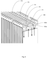
Fig. 6 shows a detailed perspective view of theFig. 5 . - The subject-matter of an invention is
tube bundle 10 for theheat exchanger 1 which is adapted for heat exchange between a first fluid and a second fluid. The first fluid may be for, example pressurized refrigerant such as carbon-dioxide circulating within theheat exchanger 1, whereas the second fluid may be, for example air. Theheat exchanger 1 aims to decrease the temperature of the first fluid. It can therefore be associated with the gas coolers, inner gas coolers, evaporators and alike. Further paragraphs provide discuss the main components and the mechanical or structural features which ensure improvement in terms of efficiency with respect to know heat exchangers. -
Fig. 1 shows asimple tube bundle 10 for aheat exchanger 1. The term "tube bundle" means that there is more than one tubular element suitable for fluid transportation, whereas the tubular elements are at least partially integrated to form one sub-component. Thetube bundle 10 may be further referred to as "the bundle" Thebundle 10 may comprisefirst tube 11, and at least onesecond tube 12. An embodiment in which more tubes are introduced, i.e. athird tube 30 and afourth tube 40, is discussed in further paragraphs. Eachtube longer walls 13 having essentially flat surface. In other words, thelonger walls 13 are substantially identical wall portions arranged in parallel and facing each other with their respective flat surfaces. Thetube shorter walls 14 connecting thelonger walls 13 to form a closed profile of thetube open ends 15. The term open end refers to a terminal ends of thetube tube - As shown in
Figs 2 and3 , in thebundle 10 theopen ends 15 of eachtube longer walls 13 of theadjacent tubes first tube 11 may be fixed to thesecond tube 12 via abridge 20 extending between median portion of correspondingshorter walls 14. Thebridge 20 allows thetube heat exchanger 1 in operational mode. Thebridge 20 allows part of the heat accumulated in thetube individual tube - The
bridge 20 allows fixing thefirst tube 11 and thesecond tube 12 together. Thickness of bridge, measured in perpendicular direction with respect to the flat surface of thelonger walls 13 may be reduced in to increase thermal resistance between the first andsecond tube second tubes - As further shown in
Figs 2 and3 , thebundle 10 may further comprise athird tube 30 and at leastfourth tube 40 arranged in series with respect to thefirst tube 11 and thesecond tube 12. Thethird tube 30 and thefourth tube 40 are the same as or similar to thefirst tube 11 and thesecond tube 12. It is apparent, that eachtube tube tubes shorter walls 14; the length- measured along thelonger walls 13, as the distance between the open ends of the tube; or as the height, measured as the distance between the outer faces of the longer walls of thesame tube tubes - As further shown foe example in
Fig. 3 , thethird tube 30 andfourth tube 40 may comprise thebridge 20 extending between median portion of correspondingshorter walls 14, similarly as thebridge 20 extending between thefirst tube 11 and thesecond tube 12. - Further, the
bundle 10 may comprise abridge 20 between thesecond tube 12 and thethird tube 30. Thebridge 20 may extend between median portion of correspondingshorter walls 14. - Alternatively, the
bundle 10 may comprise thefirst tube 11 and thesecond tube 12 connected viabridge 20, whereas the third tube and thefourth tube 40 are free. In one example, thebundle 10 may this comprise an arrangement in which thefirst tube 11 and thesecond tube 12 are sandwiched between thethird tube 30 and thefourth tube 40, or an arrangement in which thefirst tube 11 and thesecond tube 12 are arranged subsequently to thethird tube 30 and thefourth tube 40. These examples are not shown in the figures though. Similarly, thebundle 10 may comprise thefirst tube 11, thesecond tube 12 and thethird tube 30 connected viarespective bridges 20, whereas thefourth tube 40 is free in thebundle 10. - As already mentioned, at least the
first tube 11 may be bigger than theother tubes first tube 11 is greater than in theother tubes first tube 11, since it is the most promising dimension to change. Manipulating with the length of thetube bundle 10 impossible to be used in production ofheat exchanger 1. - In one of the options, the
first tube 11 may be greater than thesecond tube 12, thesecond tube 12 may be greater than thethird tube 30 and thethird tube 30 is greater than at least thefourth tube 40. In other words, the size of the tubes forming thetube bundle 10 may gradually decrease from thefirst tube 11 to the last tube forming saidbundle 10. This will allow to increase the heat transfer. - As shown in the
Fig. 3 , thebridge 20 may comprise adepletion 21 on at least one of the terminal ends thereof. Thedepletion 21 allows thetube bundle 10 to be tightly assembled with the sub-components of theheat exchanger 1. In other words, thedepletion 21 compensates the tolerances required to provide theheat exchanger 1 of reduced packaging. Thedepletion 21 extends from the plane formed by the open ends of thetubes depletion 21. As shown in the figures, the depletion may comprise a curved profile, yet other shapes are also envisaged. - The
bridge 20 may also comprise at least oneaperture 22 located between theshorter walls 14 ofadjacent tubes aperture 22 facilitates heat evacuation. In other words, the aperture increases the heat transfer between thetube bundle 10 and the ambience. Theaperture 22, may be present in different numbers, shapes and sizes. For example, thebridge 20 may comprise at least one circular aperture, a rectangular aperture, or an undefined shape. Theaperture 22 may be easily adjusted according to the needs. - The
bridge 20 may also be shifted towards any of thelonger walls 13 of theadjacent tubes bridge 20 which is deployed asymmetrically with respect to the axis extending between theshorter walls 14 ofadjacent tubes bridge 20 may also be shifted to such extent, that it forms a substantially flat surface with at least one of saidlonger walls 13. - The tube bundle may be implemented in a
heat exchanger 1, as shown inFigs 4 and5 . Theexchanger 1 may comprise, inter alia: the plurality of tube bundles 10 which arranged in a stacking direction, wherein the stacking direction is perpendicular to the flat surfaces of thetubes - The
heat exchanger 1 may further comprise at least onefirst manifold group 100 and thesecond manifold group 200. Thefirst manifold group 100 may be configured to receive one end of thetube bundle 10 and thesecond manifold group 200 may be configured to receive the other end of thetube bundle 10. In other embodiment not presented in the figures, theheat exchanger 1 may also comprise a first set comprising thetube bundle 10 and a second set comprising plurality of individual tubes arranged in a stack. The term individual refers to the tubes not comprising bridges 20. - The
first manifold group 100 may at least afirst channel 101 fluidly connected with thefirst tubes 11, so that a fluidal communication between at least twotube bundles 10 is provided. Thesecond manifold group 200 may comprise asecond channel 202 fluidly communicated with at leastsecond tubes 12. -
Figs 5 and6 show theheat exchanger 1, wherein thetube bundle 10 further comprises afirst tube 11, asecond tube 12, athird tube 30 and afourth tube 40, wherein thefirst tubes 11 form a first pass P1 for a fluid, thesecond tubes 12 form a second pass P2 for the fluid, thethird tubes 30 form a third pass P3 for the fluid, and thefourth tubes 40 form a fourth pass P4 for the for the fluid. The term pass refers to intended direction of the fluid moving in said pass in the same sense. Theheat exchanger 1 comprising four passes arranged as in present invention allow better heat evacuation, increased heat transfer and generally, increased performance of the heat exchanger while keeping relatively small packaging. - Term "manifold group" may refer to one or more manifolds arranged in the vicinity one to another. For example, "first manifold group" may refer to two manifolds arranged next to each other, wherein these manifolds share the same structural features.
- Further, the
first tubes 11 may be fluidly connected together by afirst channel 101 in thefirst manifold group 101, thesecond tubes 12 may be fluidly connected with respectivefirst tubes 11 by thesecond channel 202 in thesecond manifold group 200, thethird tubes 30 may be fluidly connected with thesecond tubes 12 by thesecond channel 202 in thefirst manifold group 100, and thefourth tubes 40 may be fluidly connected with thethird tubes 30 by thefirst channel 101 in thefirst manifold group 100. The term "channel" refers to all structural elements which allow to provide a conduit for the fluid within the manifold. - The first and the second
manifold groups header plate tubes distribution plate 100b. 200b configured to provide U-flow between thetubes same bundle 10, and thetank plate second channel manifold groups - Referring to
Fig. 6 , since themanifold groups distribution plate tank plate header plate - Further the
header plate wall portion 170 configured to support thedepletion 21 in thebridge 20 of thetube bundle 10. Thewall portion 170 is basically the portion of theheader plate depletion 21 may be in contact with thewall portion 170 to increase the robustness of the assembly. Alternatively, the depletion may be spaced away from thewall portion 170, so that the two are not in contact with each other, to compensate the thermal expansion of the sub-components during operational mode of theheat exchanger 1. - The
heat exchanger 1 may comprise an inlet and an outlet for the first fluid (not shown). Both inlet an outlet may be in form of openings fluidly connected to respective pipes of the refrigerant loop. The openings may also be connected indirectly, for example by means of connection block or other types of connectors. The pipes or the connection blocks may be fixed wherever suitable, depending on desired flow pattern or location of the inlet and outlet. - In
Fig. 6 , the arrows marked on thetube bundle 10 represent an exemplary flow direction within each pass P1, P2, P3, P4 ofrespective tube - Other variations to the disclosed embodiments can be understood and effected by those skilled in the art in practicing the claimed invention, from a study of drawings, the disclosure, and the appended claims. The mere fact that certain measures are recited in mutually different dependent claims does not indicate that a combination of these measures cannot be used to the advantage.
Claims (14)
- A tube bundle (10) for a heat exchanger (1), the bundle (10) comprising: a first tube (11), and at least one second tube (12), each tube (11, 12) comprising two juxtaposed longer walls (13) having essentially flat surface, two shorter walls (14) connecting the longer walls (13) to form a closed profile of the tube (11, 12), and an axis of elongation extending between two open ends (15) thereof, wherein the open ends (15) of each tube and are arranged next to each other and at the same level, the longer walls (13) of the adjacent tubes (11, 12) are arranged so that their flat surfaces are coplanar with respect to each other, wherein the first tube (11) is fixed to the second tube (12) via a bridge (20) extending between median portion of corresponding shorter walls (14).
- The tube bundle (10) according to claim 1, wherein the bundle (10) further comprises a third tube (30) and at least fourth tube (40) arranged in series with respect to the first tube (11) and the second tube (12).
- The tube bundle (10) according to claim 2, wherein the third tube (30) and fourth tube (40) comprise the bridge (20) extending between median portion of corresponding shorter walls (14).
- The tube bundle (10) according to claim 2 or 3, wherein the bundle (10) comprises a bridge (20) between the second tube (12) and the third tube (30), the bridge (20) extending between median portion of corresponding shorter walls (14).
- The tube bundle (10) according to any of the preceding claims, wherein at least the first tube (11) is bigger than the other tubes (12, 30, 40).
- The tube bundle (10) according to claim 5, wherein the first tube (11) is greater than the second tube (12), the second tube (12) is greater than the third tube (30) and the third tube (30) is greater than at least the fourth tube (40).
- The tube bundle (10) according to any of the preceding claims, wherein the bridge (20) comprises a depletion (21) on at least one of the terminal ends thereof.
- The tube bundle (10) according to any of the preceding claims, wherein the bridge (20) comprises at least one aperture (22) located between the shorter walls (14) of adjacent tubes (11, 12, 30, 40).
- The tube bundle (10) according to any of the preceding claim, wherein the bridge (20) is shifted towards any of the longer walls (13) of the adjacent tubes (11, 12, 30, 40), so that it forms a substantially flat surface with at least one of said longer walls (13).
- A heat exchanger (1) comprising a tube bundle (10) according to claim 1, the heat exchanger (1) comprising: the plurality of tube bundles (10) arranged in a stacking direction, the stacking direction being perpendicular to the flat surfaces of the tubes (11, 12, 30, 40), at least one first manifold group (100) configured to receive one end of the tube bundle (10) and a second manifold group (200) configured to receive the other end of the tube bundle (10), characterised in that the first manifold group (100) comprises at least a first channel (101) fluidly connected with the first tubes (11), so that a fluidal communication between at least two tube bundles (10) is provided, and in that the second manifold group (200) comprises a second channel (202) fluidly communicated with at least second tubes (12).
- The heat exchanger (1) according to claim 10, wherein the tube bundle (10) further comprises a first tube (11), a second tube (12), a third tube (30) and a fourth tube (40), wherein the first tubes (11) form a first pass (P1) for a fluid, the second tubes (12) form a second pass (P2) for the fluid, the third tubes (30) form a third pass (P3) for the fluid, and the fourth tubes (40) form a fourth pass (P4) for the for the fluid, the first tubes (11) being fluidly connected together by a first channel (101) in the first manifold group (101), the second tubes (12) being fluidly connected with respective first tubes (11) by the second channel (202) in the second manifold group (200), the third tubes (30) being fluidly connected with the second tubes (12) by the second channel (202) in the first manifold group (100), and the fourth tubes (40) are fluidly connected with the third tubes (30) by the first channel (101) in the first manifold group (100).
- The heat exchanger (1) according to any of claim 10-12, wherein the first and the second manifold groups (100, 200) comprise a header plate (100a, 200a) comprising slots (150) for receiving the tubes (11, 12, 30, 40), a distribution plate (100b, 200b) configured to form the first and the second channel (101, 202) in the manifold groups (100, 200), and the tank plate (100c, 200c) for closure of the manifold groups (100, 200).
- The heat exchanger (1) according to claim 12, wherein the header plate (100a, 200a) comprises a plurality of teeth (160) configured to fix the distribution plate (100b, 200b) and the tank plate (100c, 200c).
- The heat exchanger (1) according to any of claims 10-13, wherein the header plate (100a, 200a) comprises at least one wall portion (170) configured to support the depletion (21) in the bridge (20) of the tube bundle (10).
Priority Applications (1)
| Application Number | Priority Date | Filing Date | Title |
|---|---|---|---|
| EP22188648.4A EP4317889A1 (en) | 2022-08-04 | 2022-08-04 | A tube bundle for aheat exchanger |
Applications Claiming Priority (1)
| Application Number | Priority Date | Filing Date | Title |
|---|---|---|---|
| EP22188648.4A EP4317889A1 (en) | 2022-08-04 | 2022-08-04 | A tube bundle for aheat exchanger |
Publications (1)
| Publication Number | Publication Date |
|---|---|
| EP4317889A1 true EP4317889A1 (en) | 2024-02-07 |
Family
ID=82839425
Family Applications (1)
| Application Number | Title | Priority Date | Filing Date |
|---|---|---|---|
| EP22188648.4A Withdrawn EP4317889A1 (en) | 2022-08-04 | 2022-08-04 | A tube bundle for aheat exchanger |
Country Status (1)
| Country | Link |
|---|---|
| EP (1) | EP4317889A1 (en) |
Citations (3)
| Publication number | Priority date | Publication date | Assignee | Title |
|---|---|---|---|---|
| KR20030027610A (en) * | 2001-09-29 | 2003-04-07 | 한라공조주식회사 | Manufacturing method of tube for heat exchanger |
| US20030066633A1 (en) * | 2001-09-29 | 2003-04-10 | Halla Climate Control Corporation | Heat exchanger |
| WO2020245836A1 (en) * | 2019-06-04 | 2020-12-10 | Pranav Vikas India Pvt. Limited | Ccf heater core assembly |
-
2022
- 2022-08-04 EP EP22188648.4A patent/EP4317889A1/en not_active Withdrawn
Patent Citations (3)
| Publication number | Priority date | Publication date | Assignee | Title |
|---|---|---|---|---|
| KR20030027610A (en) * | 2001-09-29 | 2003-04-07 | 한라공조주식회사 | Manufacturing method of tube for heat exchanger |
| US20030066633A1 (en) * | 2001-09-29 | 2003-04-10 | Halla Climate Control Corporation | Heat exchanger |
| WO2020245836A1 (en) * | 2019-06-04 | 2020-12-10 | Pranav Vikas India Pvt. Limited | Ccf heater core assembly |
Similar Documents
| Publication | Publication Date | Title |
|---|---|---|
| CN102138056B (en) | Heat exchanger and housing for the heat exchanger | |
| US10337808B2 (en) | Condenser | |
| EP2108909A1 (en) | Heat exchanger provided with a fitting block | |
| US20260043615A1 (en) | Tube for heat exchanger | |
| US6543530B2 (en) | Heat exchanger having an improved pipe connecting structure | |
| CN101782296B (en) | Micro-channel heat exchanger | |
| US7311138B2 (en) | Stacking-type, multi-flow, heat exchangers and methods for manufacturing such heat exchangers | |
| US20080135222A1 (en) | Pipe connecting structure for a heat exchanger | |
| US20230168039A1 (en) | Heat exchanger | |
| JP2013164199A (en) | Heat exchanger, and method for manufacturing the same | |
| JPH04371798A (en) | Heat exchanger | |
| EP4317898A1 (en) | A manifold | |
| JPH11281287A (en) | Heat exchanger | |
| EP1975540A1 (en) | A pipe connecting structure for a heat exchanger | |
| EP4464965A1 (en) | A heat exchanger | |
| EP4464966A1 (en) | A heat exchanger | |
| EP4574477A1 (en) | A heat exchanger | |
| EP4574475A1 (en) | A heat exchanger | |
| US20190353426A1 (en) | Side member and heat exchanger having the same | |
| EP4574476A1 (en) | A manifold | |
| EP4703665A1 (en) | A heat exchanger | |
| US20080230214A1 (en) | Heat exchanger and method of manufacturing the same | |
| EP4332492A1 (en) | Heat exchanger | |
| EP2554031B1 (en) | Method and device of heat transport | |
| EP4332491A1 (en) | Heat exchanger |
Legal Events
| Date | Code | Title | Description |
|---|---|---|---|
| PUAI | Public reference made under article 153(3) epc to a published international application that has entered the european phase |
Free format text: ORIGINAL CODE: 0009012 |
|
| STAA | Information on the status of an ep patent application or granted ep patent |
Free format text: STATUS: THE APPLICATION HAS BEEN PUBLISHED |
|
| AK | Designated contracting states |
Kind code of ref document: A1 Designated state(s): AL AT BE BG CH CY CZ DE DK EE ES FI FR GB GR HR HU IE IS IT LI LT LU LV MC MK MT NL NO PL PT RO RS SE SI SK SM TR |
|
| STAA | Information on the status of an ep patent application or granted ep patent |
Free format text: STATUS: THE APPLICATION IS DEEMED TO BE WITHDRAWN |
|
| 18D | Application deemed to be withdrawn |
Effective date: 20240808 |