EP4317863A1 - Refrigerant recovery system - Google Patents
Refrigerant recovery system Download PDFInfo
- Publication number
- EP4317863A1 EP4317863A1 EP22780818.5A EP22780818A EP4317863A1 EP 4317863 A1 EP4317863 A1 EP 4317863A1 EP 22780818 A EP22780818 A EP 22780818A EP 4317863 A1 EP4317863 A1 EP 4317863A1
- Authority
- EP
- European Patent Office
- Prior art keywords
- refrigerant
- cylinder
- recovery system
- unit
- control unit
- Prior art date
- Legal status (The legal status is an assumption and is not a legal conclusion. Google has not performed a legal analysis and makes no representation as to the accuracy of the status listed.)
- Pending
Links
Images


Classifications
-
- F—MECHANICAL ENGINEERING; LIGHTING; HEATING; WEAPONS; BLASTING
- F25—REFRIGERATION OR COOLING; COMBINED HEATING AND REFRIGERATION SYSTEMS; HEAT PUMP SYSTEMS; MANUFACTURE OR STORAGE OF ICE; LIQUEFACTION SOLIDIFICATION OF GASES
- F25B—REFRIGERATION MACHINES, PLANTS OR SYSTEMS; COMBINED HEATING AND REFRIGERATION SYSTEMS; HEAT PUMP SYSTEMS
- F25B45/00—Arrangements for charging or discharging refrigerant
-
- F—MECHANICAL ENGINEERING; LIGHTING; HEATING; WEAPONS; BLASTING
- F25—REFRIGERATION OR COOLING; COMBINED HEATING AND REFRIGERATION SYSTEMS; HEAT PUMP SYSTEMS; MANUFACTURE OR STORAGE OF ICE; LIQUEFACTION SOLIDIFICATION OF GASES
- F25B—REFRIGERATION MACHINES, PLANTS OR SYSTEMS; COMBINED HEATING AND REFRIGERATION SYSTEMS; HEAT PUMP SYSTEMS
- F25B49/00—Arrangement or mounting of control or safety devices
- F25B49/005—Arrangement or mounting of control or safety devices of safety devices
-
- F—MECHANICAL ENGINEERING; LIGHTING; HEATING; WEAPONS; BLASTING
- F25—REFRIGERATION OR COOLING; COMBINED HEATING AND REFRIGERATION SYSTEMS; HEAT PUMP SYSTEMS; MANUFACTURE OR STORAGE OF ICE; LIQUEFACTION SOLIDIFICATION OF GASES
- F25B—REFRIGERATION MACHINES, PLANTS OR SYSTEMS; COMBINED HEATING AND REFRIGERATION SYSTEMS; HEAT PUMP SYSTEMS
- F25B9/00—Compression machines, plants or systems, in which the refrigerant is air or other gas of low boiling point
- F25B9/002—Compression machines, plants or systems, in which the refrigerant is air or other gas of low boiling point characterised by the refrigerant
- F25B9/008—Compression machines, plants or systems, in which the refrigerant is air or other gas of low boiling point characterised by the refrigerant the refrigerant being carbon dioxide
Definitions
- the present disclosure relates to a refrigerant recovery system.
- PTL 1 Japanese Unexamined Patent Application Publication (Translation of PCT Application) No. 2018-532091 discloses a system that recovers a refrigerant of a refrigeration unit (refrigeration cycle apparatus) to reuse the refrigerant.
- the present disclosure proposes a refrigerant recovery system that suppresses complication of the operation for reusing a refrigerant accommodated from a refrigeration cycle apparatus.
- a refrigerant recovery system of a first aspect includes a cylinder, a first detection unit, and a control unit.
- the cylinder accommodates a refrigerant filling a refrigeration cycle apparatus.
- the first detection unit detects a predetermined physical quantity for calculating a composition of the refrigerant accommodated in the cylinder.
- the control unit acquires a result of detection by the first detection unit and outputs the result as a first detection result.
- the first detection unit detects the predetermined physical quantity for calculating the composition of the refrigerant accommodated in the cylinder, and the control unit outputs the result of detection as the first detection result. Therefore, it is possible to determine whether the refrigerant is reusable, by calculating the composition of the refrigerant accommodated in the cylinder with reference to the result output from the control unit, without taking out the refrigerant from the cylinder.
- the refrigerant recovery system can suppress complication of the operation for reusing a refrigerant accommodated from a refrigeration cycle apparatus.
- a refrigerant recovery system of a second aspect is the refrigerant recovery system of the first aspect and further includes a calculation unit.
- the calculation unit calculates, based on the first detection result, composition information that is information related to the composition of the refrigerant accommodated in the cylinder.
- a refrigerant recovery system of a third aspect is the refrigerant recovery system of the second aspect and further includes a display unit.
- the display unit is attached to the cylinder and displays predetermined information.
- the control unit causes the display unit to display the composition information.
- the display unit attached to the cylinder is caused to display the composition information.
- a refrigerant recovery system of a fourth aspect is the refrigerant recovery system of the third aspect, in which the control unit refers to the composition information, and causes the display unit to display first information upon determining that a proportion of a predetermined composite is not within a predetermined range.
- a refrigerant recovery system of a fifth aspect is the refrigerant recovery system of any of the first aspect to the fourth aspect and further includes a communication unit attached to the cylinder.
- the control unit causes the communication unit to transmit the first detection result.
- the first detection result of the refrigerant accommodated can be acquired further in a site other than the site where the refrigerant is recovered. Therefore, the complication of the operation for reusing the refrigerant accommodated from the refrigeration cycle apparatus can be more effectively suppressed.
- a refrigerant recovery system of a sixth aspect is the refrigerant recovery system of any of the first aspect to the fifth aspect, in which the control unit causes the display unit to display an identification number set for the cylinder.
- the operator can easily refer to the composition information on a mixed refrigerant in the cylinder and the identification number set for the cylinder, using the display unit. Therefore, with this refrigerant recovery system, the cylinder and the composition information on the refrigerant filling the cylinder can be easily associated with each other, whereby the complication of the operation for reusing the refrigerant accommodated from the refrigeration cycle apparatus can be more effectively suppressed.
- a refrigerant recovery system of a seventh aspect is the refrigerant recovery system of any of the first aspect to the sixth aspect, in which the physical quantity is an infrared absorptivity of a gas phase of the refrigerant accommodated in the cylinder.
- the control unit outputs the infrared absorptivity of the gas phase of the refrigerant accommodated in the cylinder as the first detection result.
- a composition ratio of the refrigerant can be calculated based on the infrared absorptivity of the gas phase of the refrigerant.
- a refrigerant recovery system of an eighth aspect is the refrigerant recovery system of the seventh aspect, in which the physical quantity further includes a temperature and a pressure of the refrigerant when accommodated in the cylinder.
- composition information can be calculated more accurately than in a case where the composition information is calculated only from the infrared absorptivity of the gas phase of the refrigerant.
- a refrigerant recovery system of a ninth aspect is the refrigerant recovery system of the eighth aspect, in which the physical quantity further includes a liquid refrigerant amount of the refrigerant accommodated in the cylinder.
- the composition information can be calculated further accurately than in a case where the composition information is calculated from the infrared absorptivity of the gas phase of the refrigerant and from the temperature and the pressure of the refrigerant when accommodated in the cylinder.
- a refrigerant recovery system of a tenth aspect is the refrigerant recovery system of any of the first aspect to the ninth aspect and further includes a second detection unit.
- the second detection unit detects a predetermined impurity contained in the refrigerant accommodated in the cylinder.
- the control unit causes the display unit to display second information when the second detection unit detects the impurity.
- the operator can recognize the content of the impurity in addition to the composition information on the refrigerant, without taking out the refrigerant from the cylinder.
- the refrigerant recovery system can more effectively suppress the complication of the operation for reusing the refrigerant accommodated from a refrigeration cycle apparatus.
- a refrigerant recovery system of an eleventh aspect is the refrigerant recovery system of the tenth aspect, in which the impurity is air or water.
- a refrigerant recovery system 100 is a system that suppresses complication of an operation for recovering a refrigerant from a refrigeration cycle apparatus 500.
- the refrigeration cycle apparatus 500 is a device that provides a vapor compression refrigeration cycle using a refrigerant.
- the refrigeration cycle apparatus 500 is, for example, an air conditioning apparatus, an air purification apparatus, a heat pump hot water supply apparatus, a refrigeration apparatus, or a freezer apparatus.
- the refrigerant used in the refrigeration cycle apparatus 500 is a mixed refrigerant obtained by mixing a plurality of refrigerants at a predetermined composition ratio.
- the refrigerant used in the refrigeration cycle apparatus 500 contains, but not limited to, 2,3,3,3-tetrafluoropropene (HFO-1234yf) and carbon dioxide (R744) at a predetermined composition ratio.
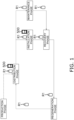
- Fig. 1 is a diagram illustrating a schematic configuration of the refrigerant circulation cycle.
- the refrigerant circulation cycle mainly includes a production phase, a distribution phase, an installation phase, a maintenance phase, a recovery phase, and a regeneration phase.
- the flow of the refrigerant is indicated by arrows.
- the refrigerant is distributed in a state of filling a dedicated container such as a cylinder R1 or the refrigeration cycle apparatus 500.
- Fig. 1 illustrates a flow of the cylinder R1 filled with the refrigerant and the refrigeration cycle apparatus 500 filled with the refrigerant.
- the refrigerant is newly produced by a refrigerant manufacturer.
- the refrigerant produced in the production phase fills the dedicated cylinder R1 and is shipped to a distributor of the refrigerant.
- Shipping destinations of the refrigerant are, for example, a manufacturer of a refrigerant using apparatus, such as the refrigeration cycle apparatus 500, an installer of the refrigerant using apparatus, and a maintainer of the refrigerant using apparatus.
- the manufacturer of the refrigerant using apparatus fills the refrigerant using apparatus with the refrigerant as necessary at the time of manufacturing or shipping of the refrigerant using apparatus.
- the refrigerant newly produced in the production phase or the refrigerant regenerated in the regeneration phase is distributed by the distributor of the refrigerant.
- the distributor purchases the refrigerant manufactured by the refrigerant manufacturer or the refrigerant regenerated by a regenerator, and sells the refrigerant to at least one of the manufacturer, the installer, and the maintainer of the refrigerant using apparatus.
- the installer installs the refrigeration cycle apparatus 500 in a predetermined installation location.
- the predetermined installation location is, for example, a property such as a building used or owned by an owner of the refrigeration cycle apparatus 500.
- the installer fills the refrigeration cycle apparatus 500 with the refrigerant distributed by the distributor at the time of installation of the refrigeration cycle apparatus 500.
- the maintainer performs maintenance management for the refrigeration cycle apparatus 500 installed. Specifically, the maintainer performs an inspection operation, a repair operation, or the like on the refrigeration cycle apparatus 500. The maintainer performs as appropriate a replacement operation for the refrigerant filling the refrigeration cycle apparatus 500 by using the cylinder R1 filled with the refrigerant, or a refilling operation of replenishing the refrigeration cycle apparatus 500 with the refrigerant.
- the refrigerant replacement operation is performed, for example, when a predetermined period of time elapses after the refrigeration cycle apparatus 500 is installed.
- the refrigerant refilling operation is performed, for example, when it is found at the time of inspection that the amount of the refrigerant filling the refrigeration cycle apparatus 500 is insufficient.
- a refrigerant recycler recovers the refrigerant filling the refrigeration cycle apparatus 500 or filling the refrigeration cycle apparatus 500 and a refrigerant pipe installed in the property.
- the recycler recovers the refrigerant when the refrigeration cycle apparatus 500 is repaired, relocated, discarded, or the like.
- Methods of recovering the refrigerant include: a method of collecting and recovering the refrigerant filling the refrigerant pipe into the refrigeration cycle apparatus 500, a method of recovering the refrigerant in the refrigeration cycle apparatus 500 and the refrigerant pipe to accommodate the refrigerant in the dedicated cylinder R1, and the like. Also when replacing the refrigerant filling the refrigeration cycle apparatus 500, the recycler takes out and recovers the refrigerant from the refrigeration cycle apparatus 500.
- the refrigerant recovered by the recycler is subjected to regeneration processing by the refrigerant regenerator.
- the refrigerant regeneration processing is, for example, processing of regenerating the refrigerant by using the recovered refrigerant as a raw material and processing of removing impurities from the recovered refrigerant.
- the regenerator receives the cylinder R1 filled with the refrigerant to be regenerated from the recycler and regenerates the refrigerant.
- the regenerated refrigerant is accommodated in the cylinder R1.
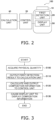
- the refrigerant recovery system 100 includes a cylinder 10, a first detection unit 20, a control unit 30, a calculation unit 40, and a display unit 50.
- Fig. 2 is a diagram illustrating a schematic configuration of the refrigerant recovery system 100.
- the cylinder 10 is a container accommodating, for recovery, the refrigerant filling the refrigeration cycle apparatus 500. Specifically, the cylinder 10 corresponds to the cylinder R1 used between the maintenance phase or the recovery phase and the regeneration phase of the refrigerant circulation cycle.
- the first detection unit 20 detects a predetermined physical quantity for calculating a composition ratio of the refrigerant accommodated in the cylinder 10.
- the first detection unit 20 in order to calculate a composition ratio of carbon dioxide in the refrigerant accommodated in the cylinder 10, the first detection unit 20 detects, as a predetermined physical quantity, the infrared absorptivity of the gas phase of the refrigerant accommodated in the cylinder 10.
- the first detection unit 20 is an infrared gas analyzer capable of measuring the infrared absorptivity of the gas phase.
- the control unit 30 acquires a result of detection by the first detection unit 20 and outputs the result as a first detection result.
- the control unit 30 acquires the infrared absorptivity of the gas phase of the refrigerant detected by the first detection unit 20 and outputs the infrared absorptivity as the first detection result to the calculation unit 40.
- the control unit 30 acquires composition information, which is a calculation result, from the calculation unit 40. Upon receiving the composition information from the calculation unit 40, the control unit 30 causes the display unit 50 to display the composition information.
- the control unit 30 is implemented by a computer.
- the control unit 30 includes a control calculation device and a storage device (both of which are not illustrated).
- a processor such as a CPU or a GPU is usable as the control calculation device.
- the control calculation device reads a program stored in the storage device and executes, based on the program, predetermined image processing and calculation processing. Furthermore, based on the program, the control calculation device may write a calculation result to the storage device and read information stored in the storage device.
- the calculation unit 40 calculates, based on the first detection result output from the control unit 30, composition information that is information related to the composition of the refrigerant accommodated in the cylinder 10. In the present embodiment, the calculation unit 40 calculates, as the composition information, the composition ratio of carbon dioxide accommodated in the cylinder 10 based on the infrared absorptivity of the gas phase of the refrigerant. The calculation unit 40 outputs the calculated composition information to the control unit 30. In the present embodiment, the calculation unit 40 is attached to the cylinder 10.
- the calculation unit 40 is implemented by a computer as in the case of the control unit 30.
- the calculation unit 40 may be implemented by the same computer as the control unit 30, or may be implemented by another computer.
- the display unit 50 is a display medium that is attached to the cylinder 10 and displays predetermined information.
- the display unit 50 acquires the predetermined information from the control unit 30 and displays the predetermined information.
- the predetermined information displayed by the display unit 50 is the composition ratio of carbon dioxide accommodated in the cylinder 10 calculated by the calculation unit 40.
- Examples of the display unit 50 include, but not limited to, a liquid crystal display, an LED display, an electrophoretic display, and the like.
- the display unit 50 is not necessarily attached to the cylinder 10.
- the display unit 50 may include a communication port, acquire the predetermined information from the control unit 30 through the communication port, and display the predetermined information.
- Fig. 3 is a flowchart of a flow of control executed by the control unit 30 and the calculation unit 40.
- the control flow in Fig. 3 starts when the control unit 30 and the calculation unit 40 are turned ON.
- step S100 the control unit 30 acquires the physical quantity (the infrared absorptivity of the gas phase of the refrigerant accommodated in the cylinder 10) detected by the first detection unit 20. Then, the processing proceeds to step S110.
- step S110 the control unit 30 outputs the detection result acquired from the first detection unit 20 to the calculation unit 40 as the first detection result. Then, the processing proceeds to step S120.
- step S120 the calculation unit 40 calculates the composition information (the composition ratio of the carbon dioxide accommodated in the cylinder 10) based on the first detection result, and outputs the composition information to the control unit 30. Then, the processing proceeds to step S130.
- step S130 the control unit 30 acquires the composition information and causes the display unit 50 to display the composition information, and ends the control flow.
- the control flow described above is executed, for example, in the maintenance phase or the recovery phase of the refrigerant circulation cycle described above. Specifically, when the refrigerant of the refrigeration cycle apparatus 500 is recovered into the cylinder 10 in the maintenance phase or the recovery phase, the operator of the maintainer or the recycler starts executing the control flow in Fig. 3 . When the control flow in Fig. 3 ends, the composition ratio of the carbon dioxide recovered into the cylinder 10 is displayed on the display unit 50 attached to the cylinder 10.
- the refrigerant recovery system 100 includes the cylinder 10, the first detection unit 20, and the control unit 30.
- the cylinder 10 accommodates the refrigerant filling the refrigeration cycle apparatus 500.
- the first detection unit 20 detects the predetermined physical quantity for calculating the composition of the refrigerant accommodated in the cylinder 10.
- the control unit 30 acquires a result of detection by the first detection unit 20 and outputs the result as a first detection result.
- the refrigerant recovered from the refrigeration cycle apparatus 500 is directly reusable, without regeneration processing of newly adding or reducing the refrigerant.
- the composition of the refrigerant may change due to, for example, partial leakage of the refrigerant.
- the recovery operation for reusing the refrigerant accommodated in the cylinder 10 is complicated because it is necessary to determine whether the refrigerant can be reused by measuring the composition of part of the refrigerant taken out from the cylinder 10.
- the refrigerant recovery system 100 In the refrigerant recovery system 100, the infrared absorptivity of the gas phase of the refrigerant accommodated in the cylinder 10 is detected by the first detection unit 20, and is output by the control unit 30 as the first detection result. Therefore, in the regeneration phase, it is possible to determine whether the refrigerant is reusable, by calculating the composition ratio of the refrigerant accommodated in the cylinder 10 with reference to the result output from the control unit 30, without taking out the refrigerant from the cylinder 10. Thus, the refrigerant recovery system 100 can suppress complication of the operation for reusing the refrigerant recovered from the refrigeration cycle apparatus 500.
- the refrigerant recovery system 100 further includes the calculation unit 40.
- the calculation unit 40 calculates, based on the first detection result, composition information that is information related to the composition of the refrigerant accommodated in the cylinder 10.
- the refrigerant recovery system 100 can calculate the composition ratio of carbon dioxide, which is the composition information on the refrigerant accommodated in the cylinder 10, based on the infrared absorptivity, which is the first detection result, of the gas phase of the refrigerant accommodated in the cylinder 10.
- the calculation unit 40 calculates the composition information, the operator can easily refer to the composition information on the refrigerant. Therefore, the complication of the operation for reusing the refrigerant recovered from the refrigeration cycle apparatus 500 can be more effectively suppressed.
- the refrigerant recovery system 100 further includes the display unit 50.
- the display unit 50 is attached to the cylinder 10 and displays predetermined information.
- the control unit 30 causes the display unit 50 to display the composition information.
- the display unit 50 attached to the cylinder 10 is caused to display the composition information.
- this refrigerant recovery system 100 the operator can easily refer to the composition information on the refrigerant using the display unit 50. Therefore, the complication of the operation for reusing the refrigerant recovered from the refrigeration cycle apparatus 500 can be more effectively suppressed.
- the physical quantity is the infrared absorptivity of the gas phase of the refrigerant accommodated in the cylinder 10.
- the control unit 30 outputs, as the first detection result, the infrared absorptivity of the gas phase of the refrigerant accommodated in the cylinder 10.
- the composition ratio of the carbon dioxide contained in the refrigerant can be calculated based on the infrared absorptivity of the gas phase of the refrigerant.
- the information that the control unit 30 causes the display unit 50 to display is not limited to the composition information.
- the control unit 30 refers to the composition information, and causes the display unit 50 to display first information upon determining that the proportion of the predetermined composition is not within a predetermined range.
- the control unit 30 refers to the composition ratio of the carbon dioxide as the composition information, and upon determining that the composition ratio of the carbon dioxide is not within a range of an allowable proportion set in advance, causes the display unit 50 to display the first information.
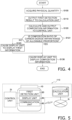
- Fig. 4 is a flowchart of a flow of control executed by the control unit 30 and the calculation unit 40 of the refrigerant recovery system 100 according to Modification 1A.
- the main difference between the control flow illustrated in Fig. 3 and the control flow illustrated in Fig. 4 is that the control flow illustrated in Fig. 4 includes step S121 and step S123. The difference will be mainly described below.
- step S120 the calculation unit 40 calculates the composition information (the composition ratio of the carbon dioxide accommodated in the cylinder 10) based on the first detection result, and outputs the composition information to the control unit 30. Then, the processing proceeds to step S121.
- step S121 the control unit 30 acquires the composition information and determines whether the composition ratio of the carbon dioxide is within the range of the allowable proportion.
- the processing proceeds to step S130, whereas when the control unit 30 determines that the composition ratio of the carbon dioxide is outside the range of the allowable proportion (No), the processing proceeds to step S123.
- the control unit 30 reads the allowable proportion of the carbon dioxide that is recorded in the storage device in advance, and compares the allowable proportion with the acquired composition information, to determine whether the composition ratio of the carbon dioxide is within the range of the allowable proportion.
- the range of the allowable proportion is a range of the composition ratio of the carbon dioxide at which the refrigerant accommodated in the cylinder 10 is reusable, without the regeneration processing of newly adding or reducing carbon dioxide in the regeneration phase of the refrigerant circulation cycle.
- the range of the allowable proportion of the carbon dioxide is, for example, 0.1% or more and 30% or less.
- step S123 the control unit 30 causes the display unit 50 to output the first information.
- step S130 the processing proceeds to step S130.
- the first information is a warning informing the operator of the fact that the reuse is not an option unless the cylinder 10 is newly filled with the refrigerant because the carbon dioxide accommodated in the cylinder 10 is outside the range of the allowable proportion.
- control unit 30 causes the display unit 50 to display an identification number set for the cylinder 10.
- the identification number is, for example, a number that is individually set for each cylinder 10 by a refrigerant recycler in order to manage the cylinder 10 in the refrigerant circulation cycle.
- the identification number is recorded in the storage device of the control unit 30.
- the control unit 30 refers to the identification number recorded in the storage device and causes the display unit 50 to display the identification number.
- this refrigerant recovery system 100 the operator can easily refer to the composition information on the refrigerant and the identification number, using the display unit 50.
- the cylinder 10 and the composition information on the refrigerant accommodated in the cylinder 10 are easily associated with each other, whereby the complication of the operation for recovering the refrigerant from the refrigeration cycle apparatus 500 is more effectively suppressed.
- the predetermined physical quantity for calculating the composition of the refrigerant detected by the first detection unit 20 is not limited to the infrared absorptivity of the gas phase of the refrigerant.
- the predetermined physical quantity may further include the temperature and the pressure of the refrigerant when accommodated in the cylinder 10.
- the first detection unit 20 includes, in addition to the infrared gas analyzer, a temperature sensor and a pressure sensor for measuring the temperature and the pressure of the refrigerant.
- step S110 of the control flow illustrated in Fig. 3 the control unit 30 acquires, as physical quantities, the infrared absorptivity of the gas phase of the refrigerant and the temperature and the pressure of the refrigerant when accommodated in the cylinder 10.
- the control unit 30 outputs these physical quantities as the first detection result to the calculation unit 40 in step S100.
- step S120 the calculation unit 40 calculates, in addition to the infrared absorptivity of the gas phase of the refrigerant, the composition information on the refrigerant accommodated in the cylinder 10 using the temperature and the pressure of the refrigerant when accommodated in the cylinder 10.
- the composition information can be calculated more accurately than in a case where the composition information is calculated based only on the infrared absorptivity of the gas phase of the refrigerant.
- the predetermined physical quantity may further include a liquid refrigerant amount accommodated in the cylinder 10.
- the first detection unit 20 includes a liquid level sensor in addition to the infrared gas analyzer, the temperature sensor, and the pressure sensor.
- the liquid level sensor measures the height of the liquid level of the liquid refrigerant in the cylinder 10 to obtain the liquid refrigerant amount.
- step S100 of the control flow illustrated in Fig. 3 the control unit 30 acquires, as physical quantities, the infrared absorptivity of the gas phase of the refrigerant, the temperature and the pressure of the refrigerant when accommodated in the cylinder 10, and the liquid refrigerant amount.
- the control unit 30 outputs these physical quantities as the first detection result to the calculation unit 40 in step S110.
- step S120 the calculation unit 40 calculates the composition information on the refrigerant accommodated in the cylinder 10 using the liquid refrigerant amount, in addition to the infrared absorptivity of the gas phase of the refrigerant and the temperature and the pressure of the refrigerant when accommodated in the cylinder 10.
- the composition information can be calculated further accurately than in a case where the composition information is calculated based on the infrared absorptivity of the gas phase of the refrigerant and the temperature and the pressure of the refrigerant when accommodated in the cylinder 10.
- the control unit 30 may cause the display unit 50 to display the first detection result together with the composition information or instead of the composition information.
- the control unit 30 of the refrigerant recovery system 100 according to the Modification 1E outputs the detection result acquired from the first detection unit 20 to the display unit 50.
- a refrigerant recovery system 110 implements the functions of the refrigerant recovery system 100 by using a processing server provided separately from the cylinder 10.
- the difference between the refrigerant recovery system 110 and the refrigerant recovery system 100 is that the refrigerant recovery system 110 includes a control unit 31 in place of the control unit 30 and a calculation unit 41 in place of the calculation unit 40, and in that the refrigerant recovery system 110 further includes a communication unit 60.
- the refrigerant recovery system 110 will be described focusing on the differences from the refrigerant recovery system 100.
- the refrigerant recovery system 110 includes the cylinder 10, the first detection unit 20, the control unit 31, the calculation unit 44, the display unit 50, and the communication unit 60.
- Fig. 5 is a diagram illustrating a schematic configuration of the refrigerant recovery system 110.
- control unit 31 outputs the first detection result to the communication unit 60 to transmit the first detection result to a network N.
- the control unit 31 acquires composition information, which is a calculation result of the calculation unit 41, via the communication unit 60. Upon receiving the composition information, the control unit 31 causes the display unit 50 to display the composition information.
- the difference between the calculation unit 41 and the calculation unit 40 is that the calculation unit 41 is not attached to the cylinder 10.
- the calculation unit 41 is coupled to the network N such as the Internet.
- the calculation unit 41 acquires the first detection result transmitted by the communication unit 60 from the network N using a communication device (not illustrated).
- the calculation unit 41 calculates, upon receiving the first detection result, the composition information, which is information related to the composition of the refrigerant accommodated in the cylinder 10, based on the first detection result.
- the calculation unit 41 transmits the calculated composition information to the network N using the communication device (not illustrated).
- the calculation unit 41 is implemented by, for example, a processing server owned by the recycler, the maintainer, or the regenerator.
- the communication unit 60 is a communication device that transmits the first detection result output from the control unit 31 and receives the composition information transmitted by the calculation unit 41.
- the communication unit 60 transmits the first detection result output from the control unit 31 to the network N using, for example, wireless communications.
- the communication unit 60 acquires the composition information calculated by the calculation unit 41 from the network N.
- the communication unit 60 is attached to the cylinder 10.
- the difference in operation between the refrigerant recovery system 100 and the refrigerant recovery system 110 is that the exchange of the first detection result and the composition information between the control unit 31 and the calculation unit 41 in the refrigerant recovery system 110 is performed via the communication unit 60 and the network N. Since there is no difference from the control flow illustrated in Fig. 3 in other respects, a detailed description of the operation will be omitted.
- the refrigerant recovery system 110 further includes the communication unit 60 attached to the cylinder 10.
- the control unit 31 causes the communication unit 60 to transmit the first detection result.
- the first detection result obtained at the timing of accommodation of the refrigerant of the refrigeration cycle apparatus 500 in the cylinder 10 in the maintenance phase or the recovery phase can be transmitted to the regenerator from the communication unit 60.
- the regenerator can obtain information indicating whether the refrigerant to be recovered is reusable without the regeneration processing, or processing such as refilling is required.
- the refrigerant recovery system 110 can more effectively suppress the complication of the operation for reusing a refrigerant accommodated from a refrigeration cycle apparatus 500.
- the display unit 50 may also be provided to the calculation unit 41. Specifically, the display unit 50 may be provided to a processing server that implements the calculation unit 41.
- a refrigerant recovery system 120 has a function of detecting a predetermined impurity in the refrigerant accommodated in the cylinder 10, in addition to the functions of the refrigerant recovery system 100.
- the difference between the refrigerant recovery system 120 and the refrigerant recovery system 100 is that the refrigerant recovery system 120 further includes a second detection unit 70 and includes a control unit 32 instead of the control unit 30.
- the refrigerant recovery system 120 will be described focusing on the differences from the refrigerant recovery system 100.
- the refrigerant recovery system 120 includes the cylinder 10, the first detection unit 20, the control unit 32, the calculation unit 40, the display unit 50, and the second detection unit 70.
- Fig. 6 is a diagram illustrating a schematic configuration of the refrigerant recovery system 120.
- the second detection unit 70 detects a predetermined impurity in the refrigerant accommodated in the cylinder 10.
- the impurity is moisture.
- the second detection unit 70 is a moisture sensor capable of detecting moisture contained in the refrigerant and outputs whether moisture is detected.
- control unit 32 acquires the result of detection by the first detection unit 20 and outputs the result as the first detection result to the calculation unit 40, and in addition, the control unit 32 causes the display unit to display second information when the second detection unit 70 detects the impurity.
- the control unit 32 acquires composition information which is a calculation result from the calculation unit 40. Upon receiving the composition information from the calculation unit 40, the control unit 32 causes the display unit 50 to display the composition information.
- Fig. 7 is a flowchart of a flow of control executed by the control unit 32 and the calculation unit 40.
- control flow illustrated in Fig. 3 The difference between the control flow illustrated in Fig. 3 and the control flow illustrated in Fig. 7 is that the control flow illustrated in Fig. 7 includes step S125 to step S127. The difference will be mainly described below.
- step S120 the calculation unit 40 calculates the composition information on the refrigerant accommodated in the cylinder 10 based on the first detection result, and outputs the composition information to the control unit 32. Then, the processing proceeds to step S125.
- step S125 the control unit 32 acquires the result of detection by the second detection unit 70 and determines whether moisture as the impurity is contained in the refrigerant.
- the processing proceeds to step S127, whereas when the impurity is not contained (No), the processing proceeds to step S130.
- step S127 the control unit 32 causes the display unit 50 to output the second information. Then, the processing proceeds to step S130.
- the second information is a warning informing the operator of the fact that the direct reuse is not an option because the refrigerant accommodated in the cylinder 10 contains moisture.
- the refrigerant recovery system 120 further includes the second detection unit 70.
- the second detection unit 70 detects a predetermined impurity (moisture) contained in the refrigerant accommodated in the cylinder 10.
- the control unit 32 causes the display unit 50 to display the second information when the second detection unit 70 detects moisture.
- the refrigerant recovery system 120 With the refrigerant recovery system 120, the operator can learn, without taking out the refrigerant from the cylinder 10, whether impurities are present in addition to the composition information on the refrigerant. Thus, the refrigerant recovery system 120 can more effectively suppress the complication of the operation for reusing the refrigerant accommodated from the refrigeration cycle apparatus 500.
- the impurity detected by the second detection unit 70 is not limited to moisture as long as the impurity is a substance that is not preferable to be contained in the refrigerant.
- the second detection unit 70 of the refrigerant recovery system 120 according to the third embodiment according to Modification 3A detects the air as an impurity.
Landscapes
- Engineering & Computer Science (AREA)
- Physics & Mathematics (AREA)
- Mechanical Engineering (AREA)
- Thermal Sciences (AREA)
- General Engineering & Computer Science (AREA)
- Sorption Type Refrigeration Machines (AREA)
Abstract
Description
- The present disclosure relates to a refrigerant recovery system.
- PTL 1 (
Japanese Unexamined Patent Application Publication (Translation of PCT Application) No. 2018-532091 - With a refrigerant circulation cycle using the system as disclosed in PTL 1, recovery of a refrigerant from a refrigeration cycle apparatus using a mixed refrigerant involves a risk of change in composition of the refrigerant due to, for example, partial leakage of the refrigerant. Thus, an operation for reusing a refrigerant accommodated in a cylinder is complicated because it is necessary to determine whether the refrigerant can be reused by measuring the composition of part of the refrigerant taken out from the cylinder.
- The present disclosure proposes a refrigerant recovery system that suppresses complication of the operation for reusing a refrigerant accommodated from a refrigeration cycle apparatus. Solution to Problem
- A refrigerant recovery system of a first aspect includes a cylinder, a first detection unit, and a control unit. The cylinder accommodates a refrigerant filling a refrigeration cycle apparatus. The first detection unit detects a predetermined physical quantity for calculating a composition of the refrigerant accommodated in the cylinder. The control unit acquires a result of detection by the first detection unit and outputs the result as a first detection result.
- In the refrigerant recovery system, the first detection unit detects the predetermined physical quantity for calculating the composition of the refrigerant accommodated in the cylinder, and the control unit outputs the result of detection as the first detection result. Therefore, it is possible to determine whether the refrigerant is reusable, by calculating the composition of the refrigerant accommodated in the cylinder with reference to the result output from the control unit, without taking out the refrigerant from the cylinder. Thus, the refrigerant recovery system can suppress complication of the operation for reusing a refrigerant accommodated from a refrigeration cycle apparatus.
- A refrigerant recovery system of a second aspect is the refrigerant recovery system of the first aspect and further includes a calculation unit. The calculation unit calculates, based on the first detection result, composition information that is information related to the composition of the refrigerant accommodated in the cylinder.
- With this refrigerant recovery system, since the calculation unit calculates the composition information, an operator can easily refer to the composition information on the refrigerant. Therefore, the complication of the operation for reusing the refrigerant accommodated from the refrigeration cycle apparatus can be more effectively suppressed.
- A refrigerant recovery system of a third aspect is the refrigerant recovery system of the second aspect and further includes a display unit. The display unit is attached to the cylinder and displays predetermined information. The control unit causes the display unit to display the composition information. In the refrigerant recovery system, the display unit attached to the cylinder is caused to display the composition information.
- With this refrigerant recovery system, the operator can easily refer to the composition information on the refrigerant using the display unit. Therefore, the complication of the operation for reusing the refrigerant accommodated from the refrigeration cycle apparatus can be more effectively suppressed.
- A refrigerant recovery system of a fourth aspect is the refrigerant recovery system of the third aspect, in which the control unit refers to the composition information, and causes the display unit to display first information upon determining that a proportion of a predetermined composite is not within a predetermined range.
- With this refrigerant recovery system, the operator can easily recognize whether the refrigerant filling the cylinder can be reused. Therefore, the complication of the operation for reusing the refrigerant accommodated from the refrigeration cycle apparatus can be more effectively suppressed.
- A refrigerant recovery system of a fifth aspect is the refrigerant recovery system of any of the first aspect to the fourth aspect and further includes a communication unit attached to the cylinder. The control unit causes the communication unit to transmit the first detection result.
- With this refrigerant recovery system, the first detection result of the refrigerant accommodated can be acquired further in a site other than the site where the refrigerant is recovered. Therefore, the complication of the operation for reusing the refrigerant accommodated from the refrigeration cycle apparatus can be more effectively suppressed.
- A refrigerant recovery system of a sixth aspect is the refrigerant recovery system of any of the first aspect to the fifth aspect, in which the control unit causes the display unit to display an identification number set for the cylinder.
- With this refrigerant recovery system, the operator can easily refer to the composition information on a mixed refrigerant in the cylinder and the identification number set for the cylinder, using the display unit. Therefore, with this refrigerant recovery system, the cylinder and the composition information on the refrigerant filling the cylinder can be easily associated with each other, whereby the complication of the operation for reusing the refrigerant accommodated from the refrigeration cycle apparatus can be more effectively suppressed.
- A refrigerant recovery system of a seventh aspect is the refrigerant recovery system of any of the first aspect to the sixth aspect, in which the physical quantity is an infrared absorptivity of a gas phase of the refrigerant accommodated in the cylinder. In the refrigerant recovery system, the control unit outputs the infrared absorptivity of the gas phase of the refrigerant accommodated in the cylinder as the first detection result.
- With this refrigerant recovery system, a composition ratio of the refrigerant can be calculated based on the infrared absorptivity of the gas phase of the refrigerant.
- A refrigerant recovery system of an eighth aspect is the refrigerant recovery system of the seventh aspect, in which the physical quantity further includes a temperature and a pressure of the refrigerant when accommodated in the cylinder.
- With this refrigerant recovery system, the composition information can be calculated more accurately than in a case where the composition information is calculated only from the infrared absorptivity of the gas phase of the refrigerant.
- A refrigerant recovery system of a ninth aspect is the refrigerant recovery system of the eighth aspect, in which the physical quantity further includes a liquid refrigerant amount of the refrigerant accommodated in the cylinder.
- With this refrigerant recovery system, the composition information can be calculated further accurately than in a case where the composition information is calculated from the infrared absorptivity of the gas phase of the refrigerant and from the temperature and the pressure of the refrigerant when accommodated in the cylinder.
- A refrigerant recovery system of a tenth aspect is the refrigerant recovery system of any of the first aspect to the ninth aspect and further includes a second detection unit. The second detection unit detects a predetermined impurity contained in the refrigerant accommodated in the cylinder. The control unit causes the display unit to display second information when the second detection unit detects the impurity.
- With this refrigerant recovery system, the operator can recognize the content of the impurity in addition to the composition information on the refrigerant, without taking out the refrigerant from the cylinder. Thus, the refrigerant recovery system can more effectively suppress the complication of the operation for reusing the refrigerant accommodated from a refrigeration cycle apparatus.
- A refrigerant recovery system of an eleventh aspect is the refrigerant recovery system of the tenth aspect, in which the impurity is air or water.
-
- [
Fig. 1] Fig. 1 is a diagram illustrating a schematic configuration of a refrigerant circulation cycle. - [
Fig. 2] Fig. 2 is a diagram illustrating a schematic configuration of arefrigerant recovery system 100. - [
Fig. 3] Fig. 3 is a flowchart of a flow of control executed by acontrol unit 30 and acalculation unit 40. - [
Fig. 4] Fig. 4 is a flowchart of a flow of control executed by thecontrol unit 30 and thecalculation unit 40 of therefrigerant recovery system 100 according to Modification 1A. - [
Fig. 5] Fig. 5 is a diagram illustrating a schematic configuration of arefrigerant recovery system 110. - [
Fig. 6] Fig. 6 is a diagram illustrating a schematic configuration of arefrigerant recovery system 120. - [
Fig. 7] Fig. 7 is a flowchart of a flow of control executed by acontrol unit 32 and thecalculation unit 40. - A
refrigerant recovery system 100 according to a first embodiment is a system that suppresses complication of an operation for recovering a refrigerant from arefrigeration cycle apparatus 500. Therefrigeration cycle apparatus 500 is a device that provides a vapor compression refrigeration cycle using a refrigerant. Therefrigeration cycle apparatus 500 is, for example, an air conditioning apparatus, an air purification apparatus, a heat pump hot water supply apparatus, a refrigeration apparatus, or a freezer apparatus. The refrigerant used in therefrigeration cycle apparatus 500 is a mixed refrigerant obtained by mixing a plurality of refrigerants at a predetermined composition ratio. The refrigerant used in therefrigeration cycle apparatus 500 contains, but not limited to, 2,3,3,3-tetrafluoropropene (HFO-1234yf) and carbon dioxide (R744) at a predetermined composition ratio. - First, an overview of a refrigerant circulation cycle in which the
refrigerant recovery system 100 is mainly used will be described.Fig. 1 is a diagram illustrating a schematic configuration of the refrigerant circulation cycle. - The refrigerant circulation cycle mainly includes a production phase, a distribution phase, an installation phase, a maintenance phase, a recovery phase, and a regeneration phase. In
Fig. 1 , the flow of the refrigerant is indicated by arrows. The refrigerant is distributed in a state of filling a dedicated container such as a cylinder R1 or therefrigeration cycle apparatus 500.Fig. 1 illustrates a flow of the cylinder R1 filled with the refrigerant and therefrigeration cycle apparatus 500 filled with the refrigerant. - In the production phase, the refrigerant is newly produced by a refrigerant manufacturer. The refrigerant produced in the production phase fills the dedicated cylinder R1 and is shipped to a distributor of the refrigerant. Shipping destinations of the refrigerant are, for example, a manufacturer of a refrigerant using apparatus, such as the
refrigeration cycle apparatus 500, an installer of the refrigerant using apparatus, and a maintainer of the refrigerant using apparatus. The manufacturer of the refrigerant using apparatus fills the refrigerant using apparatus with the refrigerant as necessary at the time of manufacturing or shipping of the refrigerant using apparatus. - In the distribution phase, the refrigerant newly produced in the production phase or the refrigerant regenerated in the regeneration phase is distributed by the distributor of the refrigerant. For example, the distributor purchases the refrigerant manufactured by the refrigerant manufacturer or the refrigerant regenerated by a regenerator, and sells the refrigerant to at least one of the manufacturer, the installer, and the maintainer of the refrigerant using apparatus.
- In the installation phase, the installer installs the
refrigeration cycle apparatus 500 in a predetermined installation location. The predetermined installation location is, for example, a property such as a building used or owned by an owner of therefrigeration cycle apparatus 500. The installer fills therefrigeration cycle apparatus 500 with the refrigerant distributed by the distributor at the time of installation of therefrigeration cycle apparatus 500. - In the maintenance phase, the maintainer performs maintenance management for the
refrigeration cycle apparatus 500 installed. Specifically, the maintainer performs an inspection operation, a repair operation, or the like on therefrigeration cycle apparatus 500. The maintainer performs as appropriate a replacement operation for the refrigerant filling therefrigeration cycle apparatus 500 by using the cylinder R1 filled with the refrigerant, or a refilling operation of replenishing therefrigeration cycle apparatus 500 with the refrigerant. The refrigerant replacement operation is performed, for example, when a predetermined period of time elapses after therefrigeration cycle apparatus 500 is installed. The refrigerant refilling operation is performed, for example, when it is found at the time of inspection that the amount of the refrigerant filling therefrigeration cycle apparatus 500 is insufficient. - In the recovery phase, a refrigerant recycler recovers the refrigerant filling the
refrigeration cycle apparatus 500 or filling therefrigeration cycle apparatus 500 and a refrigerant pipe installed in the property. The recycler recovers the refrigerant when therefrigeration cycle apparatus 500 is repaired, relocated, discarded, or the like. Methods of recovering the refrigerant include: a method of collecting and recovering the refrigerant filling the refrigerant pipe into therefrigeration cycle apparatus 500, a method of recovering the refrigerant in therefrigeration cycle apparatus 500 and the refrigerant pipe to accommodate the refrigerant in the dedicated cylinder R1, and the like. Also when replacing the refrigerant filling therefrigeration cycle apparatus 500, the recycler takes out and recovers the refrigerant from therefrigeration cycle apparatus 500. - In the regeneration phase, the refrigerant recovered by the recycler is subjected to regeneration processing by the refrigerant regenerator. The refrigerant regeneration processing is, for example, processing of regenerating the refrigerant by using the recovered refrigerant as a raw material and processing of removing impurities from the recovered refrigerant. The regenerator receives the cylinder R1 filled with the refrigerant to be regenerated from the recycler and regenerates the refrigerant. The regenerated refrigerant is accommodated in the cylinder R1.
- The
refrigerant recovery system 100 includes acylinder 10, afirst detection unit 20, acontrol unit 30, acalculation unit 40, and adisplay unit 50.Fig. 2 is a diagram illustrating a schematic configuration of therefrigerant recovery system 100. - The
cylinder 10 is a container accommodating, for recovery, the refrigerant filling therefrigeration cycle apparatus 500. Specifically, thecylinder 10 corresponds to the cylinder R1 used between the maintenance phase or the recovery phase and the regeneration phase of the refrigerant circulation cycle. - The
first detection unit 20 detects a predetermined physical quantity for calculating a composition ratio of the refrigerant accommodated in thecylinder 10. In the present embodiment, in order to calculate a composition ratio of carbon dioxide in the refrigerant accommodated in thecylinder 10, thefirst detection unit 20 detects, as a predetermined physical quantity, the infrared absorptivity of the gas phase of the refrigerant accommodated in thecylinder 10. In the present embodiment, thefirst detection unit 20 is an infrared gas analyzer capable of measuring the infrared absorptivity of the gas phase. - The
control unit 30 acquires a result of detection by thefirst detection unit 20 and outputs the result as a first detection result. In the present embodiment, thecontrol unit 30 acquires the infrared absorptivity of the gas phase of the refrigerant detected by thefirst detection unit 20 and outputs the infrared absorptivity as the first detection result to thecalculation unit 40. Thecontrol unit 30 acquires composition information, which is a calculation result, from thecalculation unit 40. Upon receiving the composition information from thecalculation unit 40, thecontrol unit 30 causes thedisplay unit 50 to display the composition information. - The
control unit 30 is implemented by a computer. Thecontrol unit 30 includes a control calculation device and a storage device (both of which are not illustrated). A processor such as a CPU or a GPU is usable as the control calculation device. The control calculation device reads a program stored in the storage device and executes, based on the program, predetermined image processing and calculation processing. Furthermore, based on the program, the control calculation device may write a calculation result to the storage device and read information stored in the storage device. - The
calculation unit 40 calculates, based on the first detection result output from thecontrol unit 30, composition information that is information related to the composition of the refrigerant accommodated in thecylinder 10. In the present embodiment, thecalculation unit 40 calculates, as the composition information, the composition ratio of carbon dioxide accommodated in thecylinder 10 based on the infrared absorptivity of the gas phase of the refrigerant. Thecalculation unit 40 outputs the calculated composition information to thecontrol unit 30. In the present embodiment, thecalculation unit 40 is attached to thecylinder 10. - The
calculation unit 40 is implemented by a computer as in the case of thecontrol unit 30. Thecalculation unit 40 may be implemented by the same computer as thecontrol unit 30, or may be implemented by another computer. - The
display unit 50 is a display medium that is attached to thecylinder 10 and displays predetermined information. Thedisplay unit 50 acquires the predetermined information from thecontrol unit 30 and displays the predetermined information. In the present embodiment, the predetermined information displayed by thedisplay unit 50 is the composition ratio of carbon dioxide accommodated in thecylinder 10 calculated by thecalculation unit 40. Examples of thedisplay unit 50 include, but not limited to, a liquid crystal display, an LED display, an electrophoretic display, and the like. Thedisplay unit 50 is not necessarily attached to thecylinder 10. In this case, thedisplay unit 50 may include a communication port, acquire the predetermined information from thecontrol unit 30 through the communication port, and display the predetermined information. -
Fig. 3 is a flowchart of a flow of control executed by thecontrol unit 30 and thecalculation unit 40. The control flow inFig. 3 starts when thecontrol unit 30 and thecalculation unit 40 are turned ON. - In step S100, the
control unit 30 acquires the physical quantity (the infrared absorptivity of the gas phase of the refrigerant accommodated in the cylinder 10) detected by thefirst detection unit 20. Then, the processing proceeds to step S110. - In step S110, the
control unit 30 outputs the detection result acquired from thefirst detection unit 20 to thecalculation unit 40 as the first detection result. Then, the processing proceeds to step S120. - In step S120, the
calculation unit 40 calculates the composition information (the composition ratio of the carbon dioxide accommodated in the cylinder 10) based on the first detection result, and outputs the composition information to thecontrol unit 30. Then, the processing proceeds to step S130. - In step S130, the
control unit 30 acquires the composition information and causes thedisplay unit 50 to display the composition information, and ends the control flow. - The control flow described above is executed, for example, in the maintenance phase or the recovery phase of the refrigerant circulation cycle described above. Specifically, when the refrigerant of the
refrigeration cycle apparatus 500 is recovered into thecylinder 10 in the maintenance phase or the recovery phase, the operator of the maintainer or the recycler starts executing the control flow inFig. 3 . When the control flow inFig. 3 ends, the composition ratio of the carbon dioxide recovered into thecylinder 10 is displayed on thedisplay unit 50 attached to thecylinder 10. - (4-1)
Therefrigerant recovery system 100 includes thecylinder 10, thefirst detection unit 20, and thecontrol unit 30. Thecylinder 10 accommodates the refrigerant filling therefrigeration cycle apparatus 500. Thefirst detection unit 20 detects the predetermined physical quantity for calculating the composition of the refrigerant accommodated in thecylinder 10. Thecontrol unit 30 acquires a result of detection by thefirst detection unit 20 and outputs the result as a first detection result. - Preferably, in the refrigerant circulation cycle, the refrigerant recovered from the
refrigeration cycle apparatus 500 is directly reusable, without regeneration processing of newly adding or reducing the refrigerant. However, when the refrigerant is accommodated in thecylinder 10 from therefrigeration cycle apparatus 500 using the mixed refrigerant, the composition of the refrigerant may change due to, for example, partial leakage of the refrigerant. Thus, the recovery operation for reusing the refrigerant accommodated in thecylinder 10 is complicated because it is necessary to determine whether the refrigerant can be reused by measuring the composition of part of the refrigerant taken out from thecylinder 10. - In the
refrigerant recovery system 100, the infrared absorptivity of the gas phase of the refrigerant accommodated in thecylinder 10 is detected by thefirst detection unit 20, and is output by thecontrol unit 30 as the first detection result. Therefore, in the regeneration phase, it is possible to determine whether the refrigerant is reusable, by calculating the composition ratio of the refrigerant accommodated in thecylinder 10 with reference to the result output from thecontrol unit 30, without taking out the refrigerant from thecylinder 10. Thus, therefrigerant recovery system 100 can suppress complication of the operation for reusing the refrigerant recovered from therefrigeration cycle apparatus 500. - (4-2)
Therefrigerant recovery system 100 further includes thecalculation unit 40. Thecalculation unit 40 calculates, based on the first detection result, composition information that is information related to the composition of the refrigerant accommodated in thecylinder 10. - With the
calculation unit 40 provided, therefrigerant recovery system 100 can calculate the composition ratio of carbon dioxide, which is the composition information on the refrigerant accommodated in thecylinder 10, based on the infrared absorptivity, which is the first detection result, of the gas phase of the refrigerant accommodated in thecylinder 10. With thisrefrigerant recovery system 100, since thecalculation unit 40 calculates the composition information, the operator can easily refer to the composition information on the refrigerant. Therefore, the complication of the operation for reusing the refrigerant recovered from therefrigeration cycle apparatus 500 can be more effectively suppressed. - (4-3)
Therefrigerant recovery system 100 further includes thedisplay unit 50. Thedisplay unit 50 is attached to thecylinder 10 and displays predetermined information. Thecontrol unit 30 causes thedisplay unit 50 to display the composition information. In therefrigerant recovery system 100, thedisplay unit 50 attached to thecylinder 10 is caused to display the composition information. - With this
refrigerant recovery system 100, the operator can easily refer to the composition information on the refrigerant using thedisplay unit 50. Therefore, the complication of the operation for reusing the refrigerant recovered from therefrigeration cycle apparatus 500 can be more effectively suppressed. - (4-4)
The physical quantity is the infrared absorptivity of the gas phase of the refrigerant accommodated in thecylinder 10. In therefrigerant recovery system 100, thecontrol unit 30 outputs, as the first detection result, the infrared absorptivity of the gas phase of the refrigerant accommodated in thecylinder 10. - With this
refrigerant recovery system 100, the composition ratio of the carbon dioxide contained in the refrigerant can be calculated based on the infrared absorptivity of the gas phase of the refrigerant. - The information that the
control unit 30 causes thedisplay unit 50 to display is not limited to the composition information. In therefrigerant recovery system 100 according to Modification 1A, thecontrol unit 30 refers to the composition information, and causes thedisplay unit 50 to display first information upon determining that the proportion of the predetermined composition is not within a predetermined range. Specifically, thecontrol unit 30 refers to the composition ratio of the carbon dioxide as the composition information, and upon determining that the composition ratio of the carbon dioxide is not within a range of an allowable proportion set in advance, causes thedisplay unit 50 to display the first information. -
Fig. 4 is a flowchart of a flow of control executed by thecontrol unit 30 and thecalculation unit 40 of therefrigerant recovery system 100 according to Modification 1A. The main difference between the control flow illustrated inFig. 3 and the control flow illustrated inFig. 4 is that the control flow illustrated inFig. 4 includes step S121 and step S123. The difference will be mainly described below. - In step S120, the
calculation unit 40 calculates the composition information (the composition ratio of the carbon dioxide accommodated in the cylinder 10) based on the first detection result, and outputs the composition information to thecontrol unit 30. Then, the processing proceeds to step S121. - In step S121, the
control unit 30 acquires the composition information and determines whether the composition ratio of the carbon dioxide is within the range of the allowable proportion. When thecontrol unit 30 determines that the composition ratio of the carbon dioxide is within the range of the allowable proportion (Yes), the processing proceeds to step S130, whereas when thecontrol unit 30 determines that the composition ratio of the carbon dioxide is outside the range of the allowable proportion (No), the processing proceeds to step S123. - More specifically, in step S121, the
control unit 30 reads the allowable proportion of the carbon dioxide that is recorded in the storage device in advance, and compares the allowable proportion with the acquired composition information, to determine whether the composition ratio of the carbon dioxide is within the range of the allowable proportion. The range of the allowable proportion is a range of the composition ratio of the carbon dioxide at which the refrigerant accommodated in thecylinder 10 is reusable, without the regeneration processing of newly adding or reducing carbon dioxide in the regeneration phase of the refrigerant circulation cycle. The range of the allowable proportion of the carbon dioxide is, for example, 0.1% or more and 30% or less. - In step S123, the
control unit 30 causes thedisplay unit 50 to output the first information. Then, the processing proceeds to step S130. The first information is a warning informing the operator of the fact that the reuse is not an option unless thecylinder 10 is newly filled with the refrigerant because the carbon dioxide accommodated in thecylinder 10 is outside the range of the allowable proportion. - With this
refrigerant recovery system 100, the operator can easily recognize whether the refrigerant filling thecylinder 10 can be reused. Therefore, the complication of the operation for reusing the refrigerant recovered from therefrigeration cycle apparatus 500 can be more effectively suppressed. - In the
refrigerant recovery system 100 according to Modification 1B, thecontrol unit 30 causes thedisplay unit 50 to display an identification number set for thecylinder 10. - The identification number is, for example, a number that is individually set for each
cylinder 10 by a refrigerant recycler in order to manage thecylinder 10 in the refrigerant circulation cycle. The identification number is recorded in the storage device of thecontrol unit 30. Thecontrol unit 30 refers to the identification number recorded in the storage device and causes thedisplay unit 50 to display the identification number. - With this
refrigerant recovery system 100, the operator can easily refer to the composition information on the refrigerant and the identification number, using thedisplay unit 50. Thus, with thisrefrigerant recovery system 100, thecylinder 10 and the composition information on the refrigerant accommodated in thecylinder 10 are easily associated with each other, whereby the complication of the operation for recovering the refrigerant from therefrigeration cycle apparatus 500 is more effectively suppressed. - The predetermined physical quantity for calculating the composition of the refrigerant detected by the
first detection unit 20 is not limited to the infrared absorptivity of the gas phase of the refrigerant. The predetermined physical quantity may further include the temperature and the pressure of the refrigerant when accommodated in thecylinder 10. - In the
refrigerant recovery system 100 according to Modification 1C, thefirst detection unit 20 includes, in addition to the infrared gas analyzer, a temperature sensor and a pressure sensor for measuring the temperature and the pressure of the refrigerant. - In the
refrigerant recovery system 100 according to Modification 1C, in step S110 of the control flow illustrated inFig. 3 , thecontrol unit 30 acquires, as physical quantities, the infrared absorptivity of the gas phase of the refrigerant and the temperature and the pressure of the refrigerant when accommodated in thecylinder 10. Thecontrol unit 30 outputs these physical quantities as the first detection result to thecalculation unit 40 in step S100. In step S120, thecalculation unit 40 calculates, in addition to the infrared absorptivity of the gas phase of the refrigerant, the composition information on the refrigerant accommodated in thecylinder 10 using the temperature and the pressure of the refrigerant when accommodated in thecylinder 10. - With this
refrigerant recovery system 100, the composition information can be calculated more accurately than in a case where the composition information is calculated based only on the infrared absorptivity of the gas phase of the refrigerant. - The predetermined physical quantity may further include a liquid refrigerant amount accommodated in the
cylinder 10. - In the
refrigerant recovery system 100 according to Modification 1D, thefirst detection unit 20 includes a liquid level sensor in addition to the infrared gas analyzer, the temperature sensor, and the pressure sensor. The liquid level sensor measures the height of the liquid level of the liquid refrigerant in thecylinder 10 to obtain the liquid refrigerant amount. - In the
refrigerant recovery system 100 according to Modification 1D, in step S100 of the control flow illustrated inFig. 3 , thecontrol unit 30 acquires, as physical quantities, the infrared absorptivity of the gas phase of the refrigerant, the temperature and the pressure of the refrigerant when accommodated in thecylinder 10, and the liquid refrigerant amount. Thecontrol unit 30 outputs these physical quantities as the first detection result to thecalculation unit 40 in step S110. In step S120, thecalculation unit 40 calculates the composition information on the refrigerant accommodated in thecylinder 10 using the liquid refrigerant amount, in addition to the infrared absorptivity of the gas phase of the refrigerant and the temperature and the pressure of the refrigerant when accommodated in thecylinder 10. - With this
refrigerant recovery system 100, the composition information can be calculated further accurately than in a case where the composition information is calculated based on the infrared absorptivity of the gas phase of the refrigerant and the temperature and the pressure of the refrigerant when accommodated in thecylinder 10. - The
control unit 30 may cause thedisplay unit 50 to display the first detection result together with the composition information or instead of the composition information. In other words, thecontrol unit 30 of therefrigerant recovery system 100 according to the Modification 1E outputs the detection result acquired from thefirst detection unit 20 to thedisplay unit 50. - A
refrigerant recovery system 110 according to a second embodiment implements the functions of therefrigerant recovery system 100 by using a processing server provided separately from thecylinder 10. The difference between therefrigerant recovery system 110 and therefrigerant recovery system 100 is that therefrigerant recovery system 110 includes acontrol unit 31 in place of thecontrol unit 30 and acalculation unit 41 in place of thecalculation unit 40, and in that therefrigerant recovery system 110 further includes acommunication unit 60. Hereinafter, therefrigerant recovery system 110 will be described focusing on the differences from therefrigerant recovery system 100. - The
refrigerant recovery system 110 includes thecylinder 10, thefirst detection unit 20, thecontrol unit 31, the calculation unit 44, thedisplay unit 50, and thecommunication unit 60.Fig. 5 is a diagram illustrating a schematic configuration of therefrigerant recovery system 110. - The difference between the
control unit 31 and thecontrol unit 30 is that thecontrol unit 31 outputs the first detection result to thecommunication unit 60 to transmit the first detection result to a network N. Thecontrol unit 31 acquires composition information, which is a calculation result of thecalculation unit 41, via thecommunication unit 60. Upon receiving the composition information, thecontrol unit 31 causes thedisplay unit 50 to display the composition information. - The difference between the
calculation unit 41 and thecalculation unit 40 is that thecalculation unit 41 is not attached to thecylinder 10. Thecalculation unit 41 is coupled to the network N such as the Internet. Thecalculation unit 41 acquires the first detection result transmitted by thecommunication unit 60 from the network N using a communication device (not illustrated). As with thecalculation unit 40, thecalculation unit 41 calculates, upon receiving the first detection result, the composition information, which is information related to the composition of the refrigerant accommodated in thecylinder 10, based on the first detection result. Thecalculation unit 41 transmits the calculated composition information to the network N using the communication device (not illustrated). Thecalculation unit 41 is implemented by, for example, a processing server owned by the recycler, the maintainer, or the regenerator. - The
communication unit 60 is a communication device that transmits the first detection result output from thecontrol unit 31 and receives the composition information transmitted by thecalculation unit 41. Thecommunication unit 60 transmits the first detection result output from thecontrol unit 31 to the network N using, for example, wireless communications. Thecommunication unit 60 acquires the composition information calculated by thecalculation unit 41 from the network N. Thecommunication unit 60 is attached to thecylinder 10. - The difference in operation between the
refrigerant recovery system 100 and therefrigerant recovery system 110 is that the exchange of the first detection result and the composition information between thecontrol unit 31 and thecalculation unit 41 in therefrigerant recovery system 110 is performed via thecommunication unit 60 and the network N. Since there is no difference from the control flow illustrated inFig. 3 in other respects, a detailed description of the operation will be omitted. - (4-1)
Therefrigerant recovery system 110 further includes thecommunication unit 60 attached to thecylinder 10. Thecontrol unit 31 causes thecommunication unit 60 to transmit the first detection result. - In the
refrigerant recovery system 110, for example, the first detection result obtained at the timing of accommodation of the refrigerant of therefrigeration cycle apparatus 500 in thecylinder 10 in the maintenance phase or the recovery phase can be transmitted to the regenerator from thecommunication unit 60. Thus, based on the first detection result obtained at the timing of accommodation of the refrigerant, the regenerator can obtain information indicating whether the refrigerant to be recovered is reusable without the regeneration processing, or processing such as refilling is required. Thus, therefrigerant recovery system 110 can more effectively suppress the complication of the operation for reusing a refrigerant accommodated from arefrigeration cycle apparatus 500. - In the
refrigerant recovery system 110, thedisplay unit 50 may also be provided to thecalculation unit 41. Specifically, thedisplay unit 50 may be provided to a processing server that implements thecalculation unit 41. - A
refrigerant recovery system 120 according to a third embodiment has a function of detecting a predetermined impurity in the refrigerant accommodated in thecylinder 10, in addition to the functions of therefrigerant recovery system 100. The difference between therefrigerant recovery system 120 and therefrigerant recovery system 100 is that therefrigerant recovery system 120 further includes asecond detection unit 70 and includes acontrol unit 32 instead of thecontrol unit 30. Hereinafter, therefrigerant recovery system 120 will be described focusing on the differences from therefrigerant recovery system 100. - The
refrigerant recovery system 120 includes thecylinder 10, thefirst detection unit 20, thecontrol unit 32, thecalculation unit 40, thedisplay unit 50, and thesecond detection unit 70.Fig. 6 is a diagram illustrating a schematic configuration of therefrigerant recovery system 120. - The
second detection unit 70 detects a predetermined impurity in the refrigerant accommodated in thecylinder 10. In the present embodiment, the impurity is moisture. Thesecond detection unit 70 is a moisture sensor capable of detecting moisture contained in the refrigerant and outputs whether moisture is detected. - The difference between the
control unit 32 and thecontrol unit 30 is that thecontrol unit 32 acquires the result of detection by thefirst detection unit 20 and outputs the result as the first detection result to thecalculation unit 40, and in addition, thecontrol unit 32 causes the display unit to display second information when thesecond detection unit 70 detects the impurity. - The
control unit 32 acquires composition information which is a calculation result from thecalculation unit 40. Upon receiving the composition information from thecalculation unit 40, thecontrol unit 32 causes thedisplay unit 50 to display the composition information. -
Fig. 7 is a flowchart of a flow of control executed by thecontrol unit 32 and thecalculation unit 40. - The difference between the control flow illustrated in
Fig. 3 and the control flow illustrated inFig. 7 is that the control flow illustrated inFig. 7 includes step S125 to step S127. The difference will be mainly described below. - In step S120, the
calculation unit 40 calculates the composition information on the refrigerant accommodated in thecylinder 10 based on the first detection result, and outputs the composition information to thecontrol unit 32. Then, the processing proceeds to step S125. - In step S125, the
control unit 32 acquires the result of detection by thesecond detection unit 70 and determines whether moisture as the impurity is contained in the refrigerant. When the impurity is contained in the refrigerant (Yes), the processing proceeds to step S127, whereas when the impurity is not contained (No), the processing proceeds to step S130. - In step S127, the
control unit 32 causes thedisplay unit 50 to output the second information. Then, the processing proceeds to step S130. The second information is a warning informing the operator of the fact that the direct reuse is not an option because the refrigerant accommodated in thecylinder 10 contains moisture. - (4-1)
Therefrigerant recovery system 120 further includes thesecond detection unit 70. Thesecond detection unit 70 detects a predetermined impurity (moisture) contained in the refrigerant accommodated in thecylinder 10. Thecontrol unit 32 causes thedisplay unit 50 to display the second information when thesecond detection unit 70 detects moisture. - With the
refrigerant recovery system 120, the operator can learn, without taking out the refrigerant from thecylinder 10, whether impurities are present in addition to the composition information on the refrigerant. Thus, therefrigerant recovery system 120 can more effectively suppress the complication of the operation for reusing the refrigerant accommodated from therefrigeration cycle apparatus 500. - The impurity detected by the
second detection unit 70 is not limited to moisture as long as the impurity is a substance that is not preferable to be contained in the refrigerant. Thesecond detection unit 70 of therefrigerant recovery system 120 according to the third embodiment according to Modification 3A detects the air as an impurity. - While embodiments of the present disclosure have been described above, it should be understood that various changes in mode and detail may be made without departing from the spirit and scope of the present disclosure as set forth in the claims.
-
- 100
- Refrigerant recovery system
- 10
- Cylinder
- 20
- First detection unit
- 30
- Control unit
- 40
- Calculation unit
- 50
- Display unit
- 60
- Communication unit
- 70
- Second detection unit
- 500
- Refrigeration cycle apparatus
- PTL 1:
Japanese Unexamined Patent Application Publication (Translation of PCT Application) No. 2018-532091
Claims (11)
- A refrigerant recovery system (100) comprising:a cylinder (10) configured to accommodate a refrigerant filling a refrigeration cycle apparatus (500);a first detection unit (20) configured to detect a predetermined physical quantity for calculating a composition of the refrigerant accommodated in the cylinder; anda control unit (30) configured to acquire a result of detection by the first detection unit and output the result as a first detection result.
- The refrigerant recovery system according to claim 1, further comprising a calculation unit (40) configured to calculate, based on the first detection result, composition information that is information related to the composition of the refrigerant accommodated in the cylinder.
- The refrigerant recovery system according to claim 2, further comprising a display unit (50) attached to the cylinder and configured to display predetermined information, wherein
the control unit causes the display unit to display the first detection result or the composition information. - The refrigerant recovery system according to claim 3, wherein
the control unit refers to the composition information, and causes the display unit to display first information upon determining that a proportion of a predetermined composite is not within a predetermined range. - The refrigerant recovery system according to any one of claims 1 to 4, further comprising a communication unit (60) attached to the cylinder, wherein
the control unit causes the communication unit to transmit the first detection result. - The refrigerant recovery system according to any one of claims 1 to 5, wherein
the control unit causes the display unit to display an identification number set for the cylinder. - The refrigerant recovery system according to any one of claims 1 to 6, wherein
the physical quantity is an infrared absorptivity of a gas phase of the refrigerant accommodated in the cylinder. - The refrigerant recovery system according to claim 7, wherein
the physical quantity further includes a temperature and a pressure of the refrigerant when accommodated in the cylinder. - The refrigerant recovery system according to claim 8, wherein
the physical quantity further includes a liquid refrigerant amount of the refrigerant accommodated in the cylinder. - The refrigerant recovery system according to any one of claims 1 to 9, further comprising a second detection unit (70) configured to detect a predetermined impurity contained in the refrigerant accommodated in the cylinder, wherein
the control unit causes the display unit to display second information when the second detection unit detects the impurity. - The refrigerant recovery system according to claim 10, wherein
the impurity is air or water.
Applications Claiming Priority (2)
| Application Number | Priority Date | Filing Date | Title |
|---|---|---|---|
| JP2021061282A JP7141000B1 (en) | 2021-03-31 | 2021-03-31 | Refrigerant recovery system |
| PCT/JP2022/015195 WO2022210607A1 (en) | 2021-03-31 | 2022-03-28 | Refrigerant recovery system |
Publications (2)
| Publication Number | Publication Date |
|---|---|
| EP4317863A1 true EP4317863A1 (en) | 2024-02-07 |
| EP4317863A4 EP4317863A4 (en) | 2024-09-18 |
Family
ID=83360840
Family Applications (1)
| Application Number | Title | Priority Date | Filing Date |
|---|---|---|---|
| EP22780818.5A Pending EP4317863A4 (en) | 2021-03-31 | 2022-03-28 | Refrigerant recovery system |
Country Status (5)
| Country | Link |
|---|---|
| US (1) | US12590742B2 (en) |
| EP (1) | EP4317863A4 (en) |
| JP (2) | JP7141000B1 (en) |
| CN (1) | CN117098963A (en) |
| WO (1) | WO2022210607A1 (en) |
Family Cites Families (23)
| Publication number | Priority date | Publication date | Assignee | Title |
|---|---|---|---|---|
| US4998413A (en) * | 1988-09-01 | 1991-03-12 | Nippondenso Co., Ltd. | Refrigerant recovery system |
| JPH0697129B2 (en) * | 1989-07-14 | 1994-11-30 | 日本電装株式会社 | Refrigerant regenerator |
| JPH0476122U (en) | 1990-11-14 | 1992-07-02 | ||
| JPH0610765U (en) * | 1991-08-26 | 1994-02-10 | 株式会社トキメック | Fluorocarbon recovery / reproduction device monitoring device |
| US5802859A (en) * | 1996-12-16 | 1998-09-08 | Hudson Technologies, Inc. | Apparatus for recovering and analyzing volatile refrigerants |
| JPH10253203A (en) * | 1997-03-13 | 1998-09-25 | Mitsubishi Electric Corp | Refrigerant recovery method |
| JP2002213845A (en) * | 2001-01-22 | 2002-07-31 | Daikin Ind Ltd | Refrigerant liquid storage tank monitoring system, its monitored side system, its monitoring side system, method for monitoring refrigerant liquid storage tank, program for refrigerant liquid simulation, and computer-readable recording medium recording the program |
| JP2002267232A (en) | 2001-03-12 | 2002-09-18 | Hitachi Ltd | Air conditioner service system and service providing device |
| EP1398618A3 (en) * | 2002-09-11 | 2004-07-28 | Horiba, Ltd. | Multi-component analyzing apparatus |
| JP2004116875A (en) | 2002-09-25 | 2004-04-15 | Horiba Ltd | Device and method of calculating additional charging amount of refrigerant |
| JP4165566B2 (en) * | 2006-01-25 | 2008-10-15 | ダイキン工業株式会社 | Air conditioner |
| EP2208007B1 (en) * | 2007-10-02 | 2015-12-09 | Carrier Corporation | Refrigerating system and method for operating the same |
| US7832222B2 (en) * | 2007-12-07 | 2010-11-16 | Spx Corporation | Background tank fill based on refrigerant composition |
| US8572992B2 (en) | 2008-03-31 | 2013-11-05 | Service Solutions U.S. Llc | Method for recovery and recharge of blend refrigerants with blend sent for reclamation |
| ITTV20110073A1 (en) * | 2011-05-30 | 2012-12-01 | Texa Spa | GAS ANALYZER SYSTEM CONFIGURED TO DETERMINE THE CONCENTRATION OF A REFRIGERANT GAS AND / OR OF CONTAMINATING GAS PRESENT IN A SELF-MULTI-AIR AIR CONDITIONING SYSTEM |
| DE102011111836A1 (en) * | 2011-08-27 | 2013-02-28 | Inficon Gmbh | Apparatus and method for refrigerant identification |
| CN108139129A (en) * | 2015-08-11 | 2018-06-08 | 特灵国际有限公司 | Refrigerant recovery and reuse |
| JP6573523B2 (en) * | 2015-10-06 | 2019-09-11 | 三菱電機ビルテクノサービス株式会社 | Refrigerant recovery device |
| JP6939902B2 (en) | 2017-12-08 | 2021-09-22 | ダイキン工業株式会社 | Refrigerant recovery management system |
| JP7159315B2 (en) * | 2018-06-29 | 2022-10-24 | ダイキン工業株式会社 | Playback information management system |
| US11953248B2 (en) * | 2019-04-19 | 2024-04-09 | Daikin Industries, Ltd. | Refrigerant management system and refrigerant management method |
| JP7249860B2 (en) | 2019-04-25 | 2023-03-31 | 三菱電機ビルソリューションズ株式会社 | Refrigerant recovery system and refrigerant recovery method |
| JP7333514B2 (en) * | 2019-07-23 | 2023-08-25 | プロステップ株式会社 | Refrigerant work support device |
-
2021
- 2021-03-31 JP JP2021061282A patent/JP7141000B1/en active Active
-
2022
- 2022-03-28 EP EP22780818.5A patent/EP4317863A4/en active Pending
- 2022-03-28 WO PCT/JP2022/015195 patent/WO2022210607A1/en not_active Ceased
- 2022-03-28 CN CN202280025611.4A patent/CN117098963A/en active Pending
- 2022-09-08 JP JP2022143337A patent/JP2022174204A/en active Pending
-
2023
- 2023-09-26 US US18/373,097 patent/US12590742B2/en active Active
Also Published As
| Publication number | Publication date |
|---|---|
| US20240019183A1 (en) | 2024-01-18 |
| CN117098963A (en) | 2023-11-21 |
| JP2022157189A (en) | 2022-10-14 |
| EP4317863A4 (en) | 2024-09-18 |
| WO2022210607A1 (en) | 2022-10-06 |
| US12590742B2 (en) | 2026-03-31 |
| JP2022174204A (en) | 2022-11-22 |
| JP7141000B1 (en) | 2022-09-22 |
Similar Documents
| Publication | Publication Date | Title |
|---|---|---|
| CN110542520B (en) | Method and system for monitoring engine fluid leakage | |
| CN105584747B (en) | Method and system for predicting remaining service life of a transport unit | |
| US7904229B2 (en) | Method for determination of engine lubrication oil consumption | |
| US11927945B2 (en) | Apparatus for assisting maintenance work, method of assisting maintenance work, and program for assisting maintenance work | |
| US20130014854A1 (en) | Fuel gas station, fuel gas filling system, and fuel gas supplying method | |
| CN115061440B (en) | Methods and apparatus for setting up single-use devices/processes | |
| US20220134844A1 (en) | Méthode de détermination du niveau de charge en fluide réfrigérant dans un circuit de refroidissement pour un système de climatisation | |
| CN106322680B (en) | Air conditioner alarm device and method | |
| CN115790804A (en) | Dynamic truck scale state monitoring method, medium, equipment and device | |
| US12590742B2 (en) | Refrigerant recovery system | |
| EP3225431B1 (en) | System for predicting tire failure location, and method for predicting tire failure location | |
| US20170219260A1 (en) | Control device and control method for bleed device | |
| CN115111703B (en) | Method, terminal and storage medium for detecting filth blockage of water-cooled air conditioner | |
| CN112177883A (en) | Refrigeration system detection method, device and readable medium | |
| CN111928415B (en) | Method, device and air conditioner for determining corresponding relationship of temperature sensor | |
| CN115655753A (en) | Electric automobile endurance mileage testing method, system, device and storage medium | |
| CN112684159B (en) | Techniques for checking analyzer status | |
| CN112577154A (en) | Method and device for detecting air conditioner abnormity | |
| CN116343444B (en) | Special type pull transportation semitrailer monitoring early warning system | |
| CN111189267A (en) | New energy automobile refrigerant charge detection system | |
| JP6234968B2 (en) | Fluid recovery and refilling equipment | |
| EP4253876A1 (en) | Refrigerant recovery device | |
| TW202509356A (en) | Predictive maintenance method for a neg vacuum pump | |
| US12546520B2 (en) | Method of evaluating refrigerant charge within a refrigeration circuit | |
| CN112179592B (en) | Refrigeration system detection method, device and readable medium |
Legal Events
| Date | Code | Title | Description |
|---|---|---|---|
| STAA | Information on the status of an ep patent application or granted ep patent |
Free format text: STATUS: THE INTERNATIONAL PUBLICATION HAS BEEN MADE |
|
| PUAI | Public reference made under article 153(3) epc to a published international application that has entered the european phase |
Free format text: ORIGINAL CODE: 0009012 |
|
| STAA | Information on the status of an ep patent application or granted ep patent |
Free format text: STATUS: REQUEST FOR EXAMINATION WAS MADE |
|
| 17P | Request for examination filed |
Effective date: 20231026 |
|
| AK | Designated contracting states |
Kind code of ref document: A1 Designated state(s): AL AT BE BG CH CY CZ DE DK EE ES FI FR GB GR HR HU IE IS IT LI LT LU LV MC MK MT NL NO PL PT RO RS SE SI SK SM TR |
|
| DAV | Request for validation of the european patent (deleted) | ||
| DAX | Request for extension of the european patent (deleted) | ||
| P01 | Opt-out of the competence of the unified patent court (upc) registered |
Free format text: CASE NUMBER: APP_38434/2024 Effective date: 20240627 |
|
| A4 | Supplementary search report drawn up and despatched |
Effective date: 20240816 |
|
| RIC1 | Information provided on ipc code assigned before grant |
Ipc: F25B 45/00 20060101AFI20240809BHEP |
|
| STAA | Information on the status of an ep patent application or granted ep patent |
Free format text: STATUS: EXAMINATION IS IN PROGRESS |
|
| 17Q | First examination report despatched |
Effective date: 20250417 |