EP4317824A1 - Air-conditioning device - Google Patents
Air-conditioning device Download PDFInfo
- Publication number
- EP4317824A1 EP4317824A1 EP22779874.1A EP22779874A EP4317824A1 EP 4317824 A1 EP4317824 A1 EP 4317824A1 EP 22779874 A EP22779874 A EP 22779874A EP 4317824 A1 EP4317824 A1 EP 4317824A1
- Authority
- EP
- European Patent Office
- Prior art keywords
- air
- conditioning device
- columnar support
- air conditioning
- heat exchanger
- Prior art date
- Legal status (The legal status is an assumption and is not a legal conclusion. Google has not performed a legal analysis and makes no representation as to the accuracy of the status listed.)
- Pending
Links
Images





Classifications
-
- F—MECHANICAL ENGINEERING; LIGHTING; HEATING; WEAPONS; BLASTING
- F04—POSITIVE - DISPLACEMENT MACHINES FOR LIQUIDS; PUMPS FOR LIQUIDS OR ELASTIC FLUIDS
- F04D—NON-POSITIVE-DISPLACEMENT PUMPS
- F04D17/00—Radial-flow pumps, e.g. centrifugal pumps; Helico-centrifugal pumps
- F04D17/02—Radial-flow pumps, e.g. centrifugal pumps; Helico-centrifugal pumps having non-centrifugal stages, e.g. centripetal
- F04D17/04—Radial-flow pumps, e.g. centrifugal pumps; Helico-centrifugal pumps having non-centrifugal stages, e.g. centripetal of transverse-flow type
-
- F—MECHANICAL ENGINEERING; LIGHTING; HEATING; WEAPONS; BLASTING
- F04—POSITIVE - DISPLACEMENT MACHINES FOR LIQUIDS; PUMPS FOR LIQUIDS OR ELASTIC FLUIDS
- F04D—NON-POSITIVE-DISPLACEMENT PUMPS
- F04D29/00—Details, component parts, or accessories
- F04D29/40—Casings; Connections of working fluid
- F04D29/42—Casings; Connections of working fluid for radial or helico-centrifugal pumps
- F04D29/4206—Casings; Connections of working fluid for radial or helico-centrifugal pumps especially adapted for elastic fluid pumps
- F04D29/4226—Fan casings
-
- F—MECHANICAL ENGINEERING; LIGHTING; HEATING; WEAPONS; BLASTING
- F04—POSITIVE - DISPLACEMENT MACHINES FOR LIQUIDS; PUMPS FOR LIQUIDS OR ELASTIC FLUIDS
- F04D—NON-POSITIVE-DISPLACEMENT PUMPS
- F04D29/00—Details, component parts, or accessories
- F04D29/66—Combating cavitation, whirls, noise, vibration or the like; Balancing
- F04D29/661—Combating cavitation, whirls, noise, vibration or the like; Balancing especially adapted for elastic fluid pumps
- F04D29/663—Sound attenuation
- F04D29/665—Sound attenuation by means of resonance chambers or interference
-
- F—MECHANICAL ENGINEERING; LIGHTING; HEATING; WEAPONS; BLASTING
- F04—POSITIVE - DISPLACEMENT MACHINES FOR LIQUIDS; PUMPS FOR LIQUIDS OR ELASTIC FLUIDS
- F04D—NON-POSITIVE-DISPLACEMENT PUMPS
- F04D29/00—Details, component parts, or accessories
- F04D29/66—Combating cavitation, whirls, noise, vibration or the like; Balancing
- F04D29/661—Combating cavitation, whirls, noise, vibration or the like; Balancing especially adapted for elastic fluid pumps
- F04D29/667—Combating cavitation, whirls, noise, vibration or the like; Balancing especially adapted for elastic fluid pumps by influencing the flow pattern, e.g. suppression of turbulence
-
- F—MECHANICAL ENGINEERING; LIGHTING; HEATING; WEAPONS; BLASTING
- F04—POSITIVE - DISPLACEMENT MACHINES FOR LIQUIDS; PUMPS FOR LIQUIDS OR ELASTIC FLUIDS
- F04D—NON-POSITIVE-DISPLACEMENT PUMPS
- F04D29/00—Details, component parts, or accessories
- F04D29/70—Suction grids; Strainers; Dust separation; Cleaning
- F04D29/701—Suction grids; Strainers; Dust separation; Cleaning especially adapted for elastic fluid pumps
- F04D29/703—Suction grids; Strainers; Dust separation; Cleaning especially adapted for elastic fluid pumps specially for fans, e.g. fan guards
-
- F—MECHANICAL ENGINEERING; LIGHTING; HEATING; WEAPONS; BLASTING
- F24—HEATING; RANGES; VENTILATING
- F24F—AIR-CONDITIONING; AIR-HUMIDIFICATION; VENTILATION; USE OF AIR CURRENTS FOR SCREENING
- F24F1/00—Room units for air-conditioning, e.g. separate or self-contained units or units receiving primary air from a central station
- F24F1/0007—Indoor units, e.g. fan coil units
- F24F1/0018—Indoor units, e.g. fan coil units characterised by fans
- F24F1/0022—Centrifugal or radial fans
-
- F—MECHANICAL ENGINEERING; LIGHTING; HEATING; WEAPONS; BLASTING
- F24—HEATING; RANGES; VENTILATING
- F24F—AIR-CONDITIONING; AIR-HUMIDIFICATION; VENTILATION; USE OF AIR CURRENTS FOR SCREENING
- F24F1/00—Room units for air-conditioning, e.g. separate or self-contained units or units receiving primary air from a central station
- F24F1/0007—Indoor units, e.g. fan coil units
- F24F1/0018—Indoor units, e.g. fan coil units characterised by fans
- F24F1/0025—Cross-flow or tangential fans
-
- F—MECHANICAL ENGINEERING; LIGHTING; HEATING; WEAPONS; BLASTING
- F24—HEATING; RANGES; VENTILATING
- F24F—AIR-CONDITIONING; AIR-HUMIDIFICATION; VENTILATION; USE OF AIR CURRENTS FOR SCREENING
- F24F1/00—Room units for air-conditioning, e.g. separate or self-contained units or units receiving primary air from a central station
- F24F1/0007—Indoor units, e.g. fan coil units
- F24F1/0043—Indoor units, e.g. fan coil units characterised by mounting arrangements
- F24F1/0057—Indoor units, e.g. fan coil units characterised by mounting arrangements mounted in or on a wall
-
- F—MECHANICAL ENGINEERING; LIGHTING; HEATING; WEAPONS; BLASTING
- F24—HEATING; RANGES; VENTILATING
- F24F—AIR-CONDITIONING; AIR-HUMIDIFICATION; VENTILATION; USE OF AIR CURRENTS FOR SCREENING
- F24F1/00—Room units for air-conditioning, e.g. separate or self-contained units or units receiving primary air from a central station
- F24F1/0007—Indoor units, e.g. fan coil units
- F24F1/0059—Indoor units, e.g. fan coil units characterised by heat exchangers
- F24F1/0063—Indoor units, e.g. fan coil units characterised by heat exchangers by the mounting or arrangement of the heat exchangers
-
- F—MECHANICAL ENGINEERING; LIGHTING; HEATING; WEAPONS; BLASTING
- F24—HEATING; RANGES; VENTILATING
- F24F—AIR-CONDITIONING; AIR-HUMIDIFICATION; VENTILATION; USE OF AIR CURRENTS FOR SCREENING
- F24F1/00—Room units for air-conditioning, e.g. separate or self-contained units or units receiving primary air from a central station
- F24F1/0007—Indoor units, e.g. fan coil units
- F24F1/0071—Indoor units, e.g. fan coil units with means for purifying supplied air
- F24F1/0073—Indoor units, e.g. fan coil units with means for purifying supplied air characterised by the mounting or arrangement of filters
-
- F—MECHANICAL ENGINEERING; LIGHTING; HEATING; WEAPONS; BLASTING
- F24—HEATING; RANGES; VENTILATING
- F24F—AIR-CONDITIONING; AIR-HUMIDIFICATION; VENTILATION; USE OF AIR CURRENTS FOR SCREENING
- F24F13/00—Details common to, or for air-conditioning, air-humidification, ventilation or use of air currents for screening
- F24F13/20—Casings or covers
-
- F—MECHANICAL ENGINEERING; LIGHTING; HEATING; WEAPONS; BLASTING
- F24—HEATING; RANGES; VENTILATING
- F24F—AIR-CONDITIONING; AIR-HUMIDIFICATION; VENTILATION; USE OF AIR CURRENTS FOR SCREENING
- F24F13/00—Details common to, or for air-conditioning, air-humidification, ventilation or use of air currents for screening
- F24F13/28—Arrangement or mounting of filters
Definitions
- the application concerned relates to an air conditioning device.
- An indoor equipment for an air conditioning device in which an air blower is installed for blowing in the air using a rotatable tangential fan.
- the casing in which the tangential fan is stored has a tongue region placed in the vicinity of the tangential fan.
- a blade pitch sound occurs between the tangential fan and the tongue region.
- an indoor equipment for an air conditioning device in order to reduce the blade pitch sound without affecting the air blowing performance, it is common practice to improve the shape of a plurality of blades disposed in the tangential fan and to improve the shape of the tongue region, (refer to Patent Literature 1 to Patent Literature 3).
- the application concerned is made in view of the issues mentioned above, and it is an objective of the application concerned to provide an air conditioning device that reduces the blade pitch sound and at the same time holds down an increase in the level of noise attributed to the wind noise.
- an air conditioning device includes a tangential fan, a columnar support, a heat exchanger that is placed between the columnar support and the tangential fan, and a mechanism configured to rotate the tangential fan around a rotation axis and cause air to pass through the heat exchanger, wherein at least some part of the columnar support is placed along a straight line that is inclined with respect to the rotation axis.
- the air condition device is able to reduce the blade pitch sound and at the same time hold down an increase in the level of noise attributed to the wind noise.
- FIG. 1 is a cross-sectional view of an indoor equipment of an air conditioning device according to a first embodiment.
- the air conditioning device includes an indoor equipment 10 and an outdoor equipment (not illustrated).
- the outdoor equipment is installed outdoors.
- the indoor equipment 10 is installed on the wall surface of an air-conditioned room that is isolated from the outdoors.
- the indoor equipment 10 includes an air blower 1, a housing 2, a heat exchanger 3, a filter 5, and a columnar support 6.
- the housing 2 includes a housing main body 21 and a front panel 22.
- the housing main body 21 is formed roughly in a box shape.
- the housing main body 21 is fixed to the wall surface on which the indoor equipment 10 is to be installed.
- the front panel 22 is formed roughly in a plate shape.
- the front panel 22 is disposed on the front side of the housing main body 21 in such a way that the frontside opening 23 gets covered by the front panel 22.
- the front panel 22 is attached to the housing main body 21 in a detachably attachable manner, and is fixed to the housing main body 21.
- an air passageway 24 is formed on the inside of the housing 2.
- a suction opening 25 is formed in the upper portion of the housing main body 21, so that the air passageway 24 gets communicated with the outside of the housing 2.
- the air blower 1 is disposed in the lower portion of the air passageway 24.
- the heat exchanger 3 includes a frontside heat exchanger 26, an upper backside heat exchanger 27, and an upper frontside heat exchanger 28.
- the frontside heat exchanger 26 is formed in a plate shape, is disposed in the air passageway 24 in between the air blower 1 and the front panel 22, and is fixed to the housing main body 21.
- the plane following the frontside heat exchanger 26 is parallel to a rotation axis 16 and is roughly perpendicular to the front back direction of the indoor equipment 10 (the direction from the front side to the back side).
- the upper backside heat exchanger 27 is formed in a plate shape.
- the upper backside heat exchanger 27 is inclined in such a way that the lower end thereof is placed more on the back side than the upper end thereof.
- the upper backside heat exchanger 27 is disposed in the air passageway 24 in between the suction opening 25 and the air blower 1, and is fixed to the housing main body 21.
- the plane following the upper backside heat exchanger 27 is parallel to the rotation axis 16.
- the heat exchanger 3 includes a plurality of fins (not illustrated) and a plurality of heat transfer tubes (not illustrated).
- the fins are formed in a plate shape and are disposed along a plurality of planes orthogonal to the rotation axis 16.
- On the inside of each heat transfer tube a flow passage is formed through which a refrigerant can flow.
- Each heat transfer tube is formed in a rod shape, penetrates through a plurality of fins, and remains thermally in contact with the fins.
- the heat transfer tubes are placed along a plurality of straight lines parallel to the rotation axis 16.
- the upper frontside heat exchanger 28 is formed in a plate shape, and is disposed in the air passageway 24 in between the suction opening 25 and the air blower 1. Moreover, the upper frontside heat exchanger 28 is inclined to have its lower end linked to the upper end of the frontside heat exchanger 26 and have its upper end linked to the upper end of the upper backside heat exchanger 27. Furthermore, the upper frontside heat exchanger 28 is fixed to the housing main body 21.
- the filter 5 is disposed in the air passageway 24 in between the heat exchanger 3 and the suction opening 25, is attached to the housing main body 21 in a detachably attachable manner, and is fixed to the housing main body 21.
- the filter 5 removes dust from the air that flows through the air passageway 24.
- the columnar support 6 is disposed in the air passageway 24 in between the heat exchanger 3 and the filter 5, and is fixed to the housing main body 21. The columnar support 6 prevents the filter 5 from making contact with the heat exchanger 3, and prevents deformation of the fins provided in the heat exchanger 3.
- the air blower 1 includes a fan casing 7 and a tangential fan 8.
- the fan casing 7 either is disposed on the inside of the housing 2 and is fixed to the housing main body 21, or is formed in an integrated manner with the housing main body 21.
- a draft air duct 11 and a vent 12 are formed in the fan casing 7.
- the draft air duct 11 is formed on the inside of the fan casing 7.
- One end of the draft air duct 11 is connected to that region in the air passageway 24 which is in between the air blower 1 and the heat exchanger 3.
- the vent 12 is formed at the lower end of the fan casing 7.
- the other end of the draft air duct 11 is connected to the vent 12, and is connected to the outside of the housing 2 of the indoor equipment 10 via the vent 12.
- the tangential fan 8 is disposed in the draft air duct 11.
- the fan casing 7 includes a frontside tongue portion 14 and a backside tongue portion 15.
- the frontside tongue portion 14 is disposed on the front side of the draft air duct 11.
- the backside tongue portion 15 is disposed on the back side of the draft air duct 11.
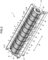
- FIG. 2 is a perspective view of the air blower 1.
- the tangential fan 8 is formed roughly in a cylindrical shape, is disposed in the draft air duct 11 along the rotation axis 16, and is supported by the fan casing 7 to be rotatable around the rotation axis 16.
- the tangential fan 8 includes a plurality of impellers 31, a plurality of dividers 32, a first endplate 33, and a second endplate 34.
- the impellers 31 are arranged in an axial direction 35 that is parallel to the rotation axis 16, and are fixed to each other via the dividers 32. From among the impellers 31, one impeller 36 includes a plurality of blades 41 as illustrated in FIG. 1 . Each blade 41 is formed in what is called an airfoil profile.
- the blades 41 are arranged in the circumferential direction centered on the rotation axis 16, and are disposed along straight lines parallel to the rotation axis 16. From among the impellers 31, each other impeller other than the impeller 36 also includes a plurality of blades 41 in an identical manner to the impeller 36.
- Each divider 32 is formed roughly in a disk shape. As illustrated in FIG. 2 , the dividers 32 are disposed along a plurality of planes orthogonal to the rotation axis 16. Moreover, each divider 32 is placed in between two impellers 31, and is fixed to the blades 41 of those two impellers 31.
- the first endplate 33 is formed roughly in a disk shape.
- the first endplate 33 is disposed at one end of the tangential fan 8 and along a plane orthogonal to the rotation axis 16, and is fixed to a plurality of blades 41 of a first type impeller 37 that, from among the impellers 31, is placed at one end.
- the second endplate 34 is formed roughly in a disk shape.
- the second endplate 34 is disposed at the other end of the tangential fan 8 and along a plane orthogonal to the rotation axis 16, and is fixed to a plurality of blades 41 of a second type impeller 38 that, from among the impellers 31, is placed at the other end.
- third type impellers other than the first type impeller 37 and the second type impeller 38 are disposed in between the first type impeller 37 and the second type impeller 38.
- the air blower 1 further includes a motor unit (not illustrated).
- the motor unit is a mechanism for rotating the tangential fan 8 around the rotation axis 16 and in a predetermined rotation direction 40 as illustrated in FIG. 1 .
- the impellers 31 are formed in such a way that, when the tangential fan 8 rotates in the rotation direction 40, the air flows through the draft air duct 11 toward the vent 12.
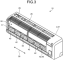
- FIG. 3 is a perspective view of the indoor equipment 10 from which the filter 5 and the front panel 22 have been removed.
- One end of the columnar support 6 is disposed at one end in the axial direction 35 of the air passageway 24, and the other end of the columnar support 6 is disposed at the other end in the axial direction 35 of the air passageway 24.
- the columnar support 6 includes a plurality of oblique columnar support portions 42. From among the oblique columnar support portions 42, one oblique columnar support portion 43 is formed in a rod shape. The straight line that follows the oblique columnar support portion 43 is inclined with respect to the axial direction 35, that is, is neither parallel to the axial direction 35 nor orthogonal to the axial direction 35.
- each other oblique columnar support portion other than the oblique columnar support portion 43 is also formed in a rod shape in an identical manner to the oblique columnar support portion 43 and is disposed along a straight line inclined with respect to the axial direction 35.
- the oblique columnar support portions 42 are formed in an integrated manner, are fixed to each other, and are fixed to the housing main body 21.
- the air conditioning device circulates a refrigerant between the indoor equipment 10 and the outdoor equipment.
- the outdoor equipment performs heat exchange between the refrigerant and the outside air.
- the air blower 1 uses the motor unit to rotate the tangential fan 8 around the rotation axis 16 and in the rotation direction 40. As a result of the rotation of the tangential fan 8, the air blower 1 supplies the air present in the air conditioned room to the air passageway 24 from the suction opening 25 of the indoor equipment 10.
- the heat exchanger 3 performs heat exchange between the air, which is supplied to the air passageway 24 from the suction opening 25, and the refrigerant; and adjusts the temperature of the air supplied to the air passageway 24. Then, the air having its temperature adjusted by the heat exchanger 3 is blown into the air conditioned room from the vent 12. As a result of performing such operations, the air conditioning device becomes able to either cool or heat the air conditioned room.
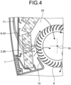
- FIG. 4 is a lateral cross-sectional view obtained when the indoor equipment 10 of the air conditioning device according to the first embodiment is cut in the plane through which one end of the oblique columnar support portion 43 (i.e., the left end portion illustrated in FIG. 3 ) passes and which is orthogonal to the rotation axis 16.
- a flowline 71 represents the flow of the air passing by the vicinity of the concerned one end of the oblique columnar support portion 43.
- the air passing through the air passageway 24 along the flowline 71 passes through the frontside heat exchanger 26 and gets supplied to the air blower 1.
- FIG. 1 is a lateral cross-sectional view obtained when the indoor equipment 10 of the air conditioning device according to the first embodiment is cut in the plane through which one end of the oblique columnar support portion 43 (i.e., the left end portion illustrated in FIG. 3 ) passes and which is orthogonal to the rotation axis 16.
- a flowline 71 represents the flow of the air passing by the vicinity of the concerned one
- a flowline 72 represents the flow of the air passing by the vicinity of the other end of the oblique columnar support portion 43.
- the air passing through the air passageway 24 along the flowline 72 passes through the frontside heat exchanger 26 and gets supplied to the air blower 1.
- the straight line followed by the oblique columnar support portion 43 is inclined with respect to the axial direction 35.
- the position of placement of the other end of the oblique columnar support portion 43 with respect to the heat exchanger 3 is different in the height direction (i.e., the direction parallel to the straight line that follows the cross-sectional surface of the frontside heat exchanger 26 illustrated in FIG. 4 ) than the position of placement of the concerned one end of the oblique columnar support portion 43 with respect to the heat exchanger 3.
- the flowline 72 followed by the air flowing in the vicinity of the other end of the oblique columnar support portion 43 is different than the flowline 71 followed by the air flowing in the vicinity of the other end of the oblique columnar support portion 43.
- the wind noise is generated when the air passes therethrough.
- the wind noise includes a one end wind noise and an other end wind noise.
- the one end wind noise is generated in the portion through which passes the air that flows along the flowline 71.
- the other end wind noise is generated in the portion through which passes the air that flows along the flowline 72.
- the wind noise gets generated at the places at which the distance between the frontside heat exchanger 26 and the tangential fan 8 is the shortest (i.e., the wind noise gets generated in the vicinity of the dead ends of the flowlines 71 and 72 on the side of the tangential fan 8). With reference to those places, the oblique columnar support portion 43 is positioned on the upstream side of the flow of the air.
- the position of the oblique columnar support portion 43 is different, then the flow velocity of the air at those places also differs.
- the position of the oblique columnar support portion 43 at the other end has a position overlap on the upstream side of the flow of the air. That is, the flow velocity of the air that flows along the flowline 71 and passes through the frontside heat exchanger 26 is greater than the flow velocity of the air that flows along the flowline 72 and passes through the frontside heat exchanger 26.
- the frequency of the wind noise varies according to the flow velocity. Conventionally, the wind noise having a constant frequency is generated from one end to the other end of the frontside heat exchanger 26 in the axial direction 35.
- the resonance results in a high level of noise.
- the frequency of the wind noise is dispersed across the ends of the heat exchanger 3 in the axial direction 35. That enables achieving reduction in the portion in which the sound resonating with the blade pitch sound is generated. As a result, the noise attributed to the resonance gets reduced.
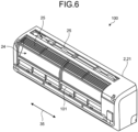
- FIG. 6 is a perspective view of an indoor equipment 100 of an air conditioning device according to a first comparison example.
- the columnar support 6 in the indoor equipment 10 of the air conditioning device according to the first embodiment is replaced with a columnar support 101, and the other constituent elements are same as the constituent elements of the indoor equipment 10 of the air conditioning device according to the first embodiment described above.
- the columnar support 101 is formed in a rod shape, is placed along a straight line parallel to the axial direction 35, and is fixed to the housing main body 21.
- a plurality of wind noises generated in a plurality of different portions in the axial direction 35 has the same frequency.
- the indoor equipment 10 of the air conditioning device according to the first embodiment enables holding down an increase in the level of noise attributed to the wind noise.
- the indoor equipment 10 of the air conditioning device includes: the tangential fan 8; the columnar support 6; the heat exchanger 3 disposed between the columnar support 6 and the tangential fan 8; and the motor unit that rotates the tangential fan 8 around the rotation axis 16 and lets the air pass through the heat exchanger 3.
- the oblique columnar support portion 43 is disposed along a straight line that is inclined with respect to the rotation axis 16.
- the columnar support 6 is made of a plurality of oblique columnar support portions 42 disposed along a plurality of straight lines inclined with respect to the axial direction 35.
- the indoor equipment 10 of the air conditioning device according to the first embodiment enables holding down an increase in the level of noise, which is attributed to the wind noise, across the full width of the air blower 1 in the axial direction 35.
- the indoor equipment 10 of the air conditioning device according to the first embodiment further includes the filter 5 that removes dust from the air.
- the columnar support 6 is disposed in between the filter 5 and the heat exchanger 3. That is, the columnar support 6 is used for preventing the filter 5 from making contact with the heat exchanger 3.
- the filter 5 since the filter 5 is prevented from making contact with the heat exchanger 3, it also becomes possible to prevent deformation of the fins provided in the heat exchanger 3.
- FIG. 7 is a perspective view of the indoor equipment 80, from which the front panel 22 has been removed, of the air conditioning device according to the second embodiment.
- FIG. 8 is a planar view of the filter 81 of the indoor equipment 80 of the air conditioning device according to the second embodiment.
- the filter 81 includes a filter main body 82, a frame 83, and a plurality of sash bars 84.
- the filter main body 82 is formed in the shape of a rectangular sheet.
- the filter main body 82 is formed to be reticular so that the air can pass in the thickness direction of the filter 81 and that dust is removed from the air passing through the filter 81.
- the frame 83 is formed in a rod shape around the filter main body 82, and is fixed to the rim of the filter main body 82.
- the frame 83 prevents deformation of the filter 81 from a predetermined shape.
- the sash bars 84 are formed in a rod shape.
- the sash bars 84 are disposed along the filter main body 82 and are fixed to the filter main body 82.
- the sash bars 84 are fixed to each other in an integrated manner and are also fixed to the frame 83.
- the sash bars 84 prevent deformation of the filter 81 from a predetermined shape.
- the sash bars 84 include columnar support portions mentioned in claims.
- the columnar support portions included in the sash bars 84 include a plurality of columnar support portions 85 and a plurality of oblique columnar support portions 86.
- the straight lines followed by the columnar support portions 85 are either parallel to the axial direction 35 or orthogonal to the axial direction 35.
- the straight lines followed by the oblique columnar support portions 86 are inclined with respect to the axial direction 35, that is, are neither parallel to the axial direction 35 nor orthogonal to the axial direction 35.
- the oblique columnar support portions 86 have different positions in the height direction (i.e., the direction parallel to the straight line that follows the cross-sectional surface of the frontside heat exchanger 26 illustrated in FIG. 4 ) than the position of placement of the concerned one end of oblique columnar support portion 43 with respect to the heat exchanger 3.
- the flow velocity of the air is ensured to be different according to the position of the oblique columnar support portion 43, a plurality of wind noises generated at a plurality of parts can be ensured to be different from each other.
- the indoor equipment 80 of the air conditioning device according to the second embodiment it becomes possible to hold down an increase in the level of noise attributed to the overlapping of a plurality of wind noises generated at a plurality of different positions in the axial direction 35.
- FIG. 9 is a perspective view of the indoor equipment 80, from which the front panel 22 has been removed, of the air conditioning device according to the second embodiment.
- FIG. 10 is a planar view of the filter 201 of the indoor equipment 200 of the air conditioning device according to the second comparison example.
- the filter 201 is configured by omitting the oblique columnar support portions 86 from the filter 81, and the other constituent elements are same as the constituent elements of the filter 81. That is, the filter 201 includes the filter main body 82, the frame 83, and the columnar support portions 85.
- the indoor equipment 80 of the air conditioning device according to the second embodiment enables holding down an increase in the level of noise attributed to the wind noise.
- the indoor equipment 80 of the air conditioning device according to the second embodiment described above has the oblique columnar support portions 42 disposed therein.
- the oblique columnar support portions 42 can be replaced with the columnar support 101 of the indoor equipment 100 of the air conditioning device according to the first comparison example.
- the presence of the oblique columnar support portions 86 enables holding down an increase in the level of noise attributed to the wind noise.
- FIG. 11 is a lateral cross-sectional view of the indoor equipment 90 of the air conditioning device according to the third embodiment.
- the front panel 91 includes a front panel main body 92 and a plurality of reinforcing members 93.
- the front panel main body 92 is disposed on the front side of the housing main body 21 in such a way that the frontside opening 23 gets covered by the front panel 91.
- the front panel main body 92 is attached in a detachably attachable manner to the housing main body 21, and is fixed to the housing main body 21.
- a plurality of frontside suction openings 94 is formed in the front panel main body 92.
- FIG. 12 is a perspective view of the front panel 91 of the indoor equipment 90 of the air conditioning device according to the third embodiment.
- the frontside suction openings 94 are formed at the upper end of the front panel main body 92 and in the axial direction 35.
- the reinforcing members 93 are disposed in a corresponding manner to the frontside suction openings 94. From among the reinforcing members 93, one reinforcing member 95 corresponding to a frontside suction opening 94-1 is formed in the vicinity of the frontside suction opening 94-1, is formed parallel to the axial direction 35, and is formed substantially orthogonal to the plane of the front panel 91.
- the upper end of the reinforcing member 95 is placed at the upper end of the frontside suction opening 94-1 and is fixed to the front panel main body 92.
- the reinforcing member 95 is so formed that a lower end 96 thereof follows a straight line.
- the straight line followed by the lower end 96 of the reinforcing member 95 is inclined with respect to the axial direction 35, that is, is neither parallel to the axial direction 35 nor orthogonal to the axial direction 35.
- the other reinforcing members other than the reinforcing member 95 are also formed in an identical manner to the reinforcing member 95.
- the indoor equipment 90 of the air conditioning device As a result of having a plurality of reinforcing members 93 in the front panel 91, it becomes possible to reinforce the front panel 91 in such a way that the front panel main body 92 does not get deformed even when the frontside suction openings 94 are formed on the front panel 91.
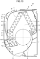
- FIG. 13 is a lateral cross-sectional view illustrating a cross-sectional surface on which the plane having one end of the oblique columnar support portion 43 passing therethrough intersects with the indoor equipment 90 of the air conditioning device according to the third embodiment.
- the air that has passes by the vicinity of the other end of the reinforcing member 95 in the axial direction 35 passes through the air passageway 24 along a flowline 97, then passes through the frontside heat exchanger 26, and is then supplied to the air blower 1.
- the position of placement of the other end of the lower end 96 is different than the position of placement of the concerned one end of the lower end 96. Since the position of the other end of the lower end 96 is different in the height direction (i.e., the direction parallel to the straight line that follows the cross-sectional surface of the frontside heat exchanger 26 illustrated in FIG. 13 ) than the position of the concerned one end of the lower end 96, the flowline 97 followed by the air flowing in the vicinity of the other end of the reinforcing member 95 is different than the flowline 98 followed by the air flowing in the vicinity of the concerned one end of the reinforcing member 95.
- the reinforcing members 93 can ensure that different wind noises are generated in a plurality of parts having mutually different positions in the frontside tongue portion 14 in the axial direction 35.
- the indoor equipment 90 of the air conditioning device according to the third embodiment it becomes possible to hold down an increase in the level of noise attributed to the overlapping of a plurality of wind noises generated at a plurality of different positions in the axial direction 35.
- FIG. 14 is a perspective view of the front panel 301 of the indoor equipment of the air conditioning device according to the third comparison example.
- the reinforcing members 93 of the front panel 91 explained earlier are replaced with a plurality of reinforcing members 302, and the other constituent elements are same as the constituent elements of the front panel 91.
- one reinforcing member 304 corresponding to the frontside suction opening 94-1 is placed close to the frontside suction opening 94-1 and along a vertical plane parallel to the axial direction 35.
- the upper end of the reinforcing member 304 is placed at the upper end of the frontside suction opening 94-1 and is fixed to the front panel main body 92.
- the reinforcing member 304 is formed in such a way that a lower end 305 thereof follows a straight line.
- the straight line followed by the lower end 305 of the reinforcing member 304 is parallel to the axial direction 35.
- the other reinforcing members other than the reinforcing member 304 are also formed in an identical manner to the reinforcing member 304.
- the indoor equipment 90 of the air conditioning device according to the third embodiment enables holding down an increase in the level of noise attributed to the wind noise.
- the indoor equipment 90 of the air conditioning device according to the third embodiment described above has the oblique columnar support portions 42 disposed therein.
- the oblique columnar support portions 42 can be replaced with the columnar support 101 of the indoor equipment 100 of the air conditioning device according to the first comparison example.
- the presence of the reinforcing members 93 enables holding down an increase in the level of noise attributed to the wind noise.
- the front panel main body 92 has the frontside suction openings 94 formed thereon.
- the frontside suction openings 94 can be absent.
- the tangential fan 8 is disposed that sucks in the air from a radial direction and blows out the air from another radial direction.
- a multiblade fan can be disposed that is different than a tangential fan. Examples of a multiblade fan include a fan that sucks in the air from a radial direction and blows out the air from the axial direction 35. In such an indoor equipment too, in an identical manner to the indoor equipment of the air conditioning device according to the embodiments, it becomes possible to hold down an increase in the level of noise attributed to the wind noise.
Landscapes
- Engineering & Computer Science (AREA)
- Mechanical Engineering (AREA)
- General Engineering & Computer Science (AREA)
- Chemical & Material Sciences (AREA)
- Combustion & Propulsion (AREA)
- Physics & Mathematics (AREA)
- Thermal Sciences (AREA)
- Air Filters, Heat-Exchange Apparatuses, And Housings Of Air-Conditioning Units (AREA)
- Structures Of Non-Positive Displacement Pumps (AREA)
- Central Air Conditioning (AREA)
Abstract
Description
- The application concerned relates to an air conditioning device.
- An indoor equipment for an air conditioning device is known in which an air blower is installed for blowing in the air using a rotatable tangential fan. The casing in which the tangential fan is stored has a tongue region placed in the vicinity of the tangential fan. When the tangential fan rotates in such an indoor equipment for an air conditioning device, a blade pitch sound occurs between the tangential fan and the tongue region. As far as an indoor equipment for an air conditioning device is concerned, in order to reduce the blade pitch sound without affecting the air blowing performance, it is common practice to improve the shape of a plurality of blades disposed in the tangential fan and to improve the shape of the tongue region, (refer to
Patent Literature 1 to Patent Literature 3). -
- [Patent Literature 1]
Japanese Laid-open Patent Publication No. 2007-10240 - [Patent Literature 2]
Japanese Laid-open Patent Publication No. 2007-40543 - [Patent Literature 3]
Japanese Laid-open Patent Publication No. 2010-156210 - In an indoor equipment for an air conditioning device, due the wind noise generated in the space through which the blown air passes, the level of noise undergoes further increase.
- The application concerned is made in view of the issues mentioned above, and it is an objective of the application concerned to provide an air conditioning device that reduces the blade pitch sound and at the same time holds down an increase in the level of noise attributed to the wind noise.
- According to an aspect of an embodiment, an air conditioning device includes a tangential fan, a columnar support, a heat exchanger that is placed between the columnar support and the tangential fan, and a mechanism configured to rotate the tangential fan around a rotation axis and cause air to pass through the heat exchanger, wherein at least some part of the columnar support is placed along a straight line that is inclined with respect to the rotation axis.
- The air condition device according to the application concerned is able to reduce the blade pitch sound and at the same time hold down an increase in the level of noise attributed to the wind noise.
-
-
FIG. 1 is a cross-sectional view of an indoor equipment of an air conditioning device according to a first embodiment. -
FIG. 2 is a perspective view of an air blower. -
FIG. 3 is a perspective view of the indoor equipment from which a filter and a front panel have been removed. -
FIG. 4 is a lateral cross-sectional view illustrating a cross-sectional surface on which the plane having one end of an oblique columnar support portion passing therethrough intersects with the indoor equipment of the air conditioning device according to the first embodiment. -
FIG. 5 is another lateral cross-sectional view illustrating a cross-sectional surface on which the plane having the other end of the oblique columnar support portion passing therethrough intersects with the indoor equipment of the air conditioning device according to the first embodiment. -
FIG. 6 is a perspective view of an indoor equipment of an air conditioning device according to a first comparison example. -
FIG. 7 is a perspective view of an indoor equipment, from which the front panel has been removed, of an air conditioning device according to a second embodiment. -
FIG. 8 is a planar view of a filter of the indoor equipment of the air conditioning device according to the second embodiment. -
FIG. 9 is a perspective view of the indoor equipment, from which the front panel has been removed, of the air conditioning device according to the second embodiment. -
FIG. 10 is a planar view of a filter of the indoor equipment of the air conditioning device according to the second comparison example. -
FIG. 11 is a lateral cross-sectional view of an indoor equipment of an air conditioning device according to a third embodiment. -
FIG. 12 is a perspective view of a front panel of the indoor equipment of the air conditioning device according to the third embodiment. -
FIG. 13 is a lateral cross-sectional view illustrating a cross-sectional surface on which the plane having one end of the oblique columnar support portion passing therethrough intersects with the indoor equipment of the air conditioning device according to the third embodiment. -
FIG. 14 is a perspective view of a front panel of an indoor equipment of an air conditioning device according to a third comparison example. - Exemplary embodiments of an indoor equipment according to the application concerned are described below with reference to the accompanying drawings. However, the application concerned is not limited by the embodiments described below. In the following explanation, identical constituent elements are referred to by the same reference numerals, and the same explanation is not repeated.
-
FIG. 1 is a cross-sectional view of an indoor equipment of an air conditioning device according to a first embodiment. The air conditioning device includes anindoor equipment 10 and an outdoor equipment (not illustrated). The outdoor equipment is installed outdoors. Theindoor equipment 10 is installed on the wall surface of an air-conditioned room that is isolated from the outdoors. Theindoor equipment 10 includes anair blower 1, ahousing 2, aheat exchanger 3, afilter 5, and acolumnar support 6. - The
housing 2 includes a housingmain body 21 and afront panel 22. The housingmain body 21 is formed roughly in a box shape. The housingmain body 21 is fixed to the wall surface on which theindoor equipment 10 is to be installed. On the front side of the housingmain body 21, a frontside opening 23 is formed. Thefront panel 22 is formed roughly in a plate shape. Thefront panel 22 is disposed on the front side of the housingmain body 21 in such a way that the frontside opening 23 gets covered by thefront panel 22. Moreover, thefront panel 22 is attached to the housingmain body 21 in a detachably attachable manner, and is fixed to the housingmain body 21. - On the inside of the
housing 2, anair passageway 24 is formed. In the upper portion of the housingmain body 21, a suction opening 25 is formed so that theair passageway 24 gets communicated with the outside of thehousing 2. Theair blower 1 is disposed in the lower portion of theair passageway 24. - The
heat exchanger 3 includes a frontside heat exchanger 26, an upper backside heat exchanger 27, and an upper frontside heat exchanger 28. The frontside heat exchanger 26 is formed in a plate shape, is disposed in theair passageway 24 in between theair blower 1 and thefront panel 22, and is fixed to the housingmain body 21. The plane following the frontside heat exchanger 26 is parallel to arotation axis 16 and is roughly perpendicular to the front back direction of the indoor equipment 10 (the direction from the front side to the back side). The upper backside heat exchanger 27 is formed in a plate shape. Moreover, the upper backside heat exchanger 27 is inclined in such a way that the lower end thereof is placed more on the back side than the upper end thereof. Furthermore, the upper backside heat exchanger 27 is disposed in theair passageway 24 in between the suction opening 25 and theair blower 1, and is fixed to the housingmain body 21. The plane following the upper backside heat exchanger 27 is parallel to therotation axis 16. - The
heat exchanger 3 includes a plurality of fins (not illustrated) and a plurality of heat transfer tubes (not illustrated). The fins are formed in a plate shape and are disposed along a plurality of planes orthogonal to therotation axis 16. On the inside of each heat transfer tube, a flow passage is formed through which a refrigerant can flow. Each heat transfer tube is formed in a rod shape, penetrates through a plurality of fins, and remains thermally in contact with the fins. The heat transfer tubes are placed along a plurality of straight lines parallel to therotation axis 16. - The upper frontside heat exchanger 28 is formed in a plate shape, and is disposed in the
air passageway 24 in between thesuction opening 25 and theair blower 1. Moreover, the upper frontside heat exchanger 28 is inclined to have its lower end linked to the upper end of the frontside heat exchanger 26 and have its upper end linked to the upper end of the upper backside heat exchanger 27. Furthermore, the upper frontside heat exchanger 28 is fixed to the housingmain body 21. - The
filter 5 is disposed in theair passageway 24 in between theheat exchanger 3 and thesuction opening 25, is attached to the housingmain body 21 in a detachably attachable manner, and is fixed to the housingmain body 21. Thefilter 5 removes dust from the air that flows through theair passageway 24. Thecolumnar support 6 is disposed in theair passageway 24 in between theheat exchanger 3 and thefilter 5, and is fixed to the housingmain body 21. Thecolumnar support 6 prevents thefilter 5 from making contact with theheat exchanger 3, and prevents deformation of the fins provided in theheat exchanger 3. - The
air blower 1 includes afan casing 7 and atangential fan 8. Thefan casing 7 either is disposed on the inside of thehousing 2 and is fixed to the housingmain body 21, or is formed in an integrated manner with the housingmain body 21. In thefan casing 7, adraft air duct 11 and avent 12 are formed. Thedraft air duct 11 is formed on the inside of thefan casing 7. One end of thedraft air duct 11 is connected to that region in theair passageway 24 which is in between theair blower 1 and theheat exchanger 3. Thevent 12 is formed at the lower end of thefan casing 7. The other end of thedraft air duct 11 is connected to thevent 12, and is connected to the outside of thehousing 2 of theindoor equipment 10 via thevent 12. - The
tangential fan 8 is disposed in thedraft air duct 11. Thefan casing 7 includes afrontside tongue portion 14 and abackside tongue portion 15. Thefrontside tongue portion 14 is disposed on the front side of thedraft air duct 11. Thebackside tongue portion 15 is disposed on the back side of thedraft air duct 11. When thetangential fan 8 is rotary driven by a mechanism explained later, an air current is generated that passes through theheat exchanger 3. -
FIG. 2 is a perspective view of theair blower 1. Thetangential fan 8 is formed roughly in a cylindrical shape, is disposed in thedraft air duct 11 along therotation axis 16, and is supported by thefan casing 7 to be rotatable around therotation axis 16. Thetangential fan 8 includes a plurality ofimpellers 31, a plurality ofdividers 32, afirst endplate 33, and asecond endplate 34. Theimpellers 31 are arranged in anaxial direction 35 that is parallel to therotation axis 16, and are fixed to each other via thedividers 32. From among theimpellers 31, oneimpeller 36 includes a plurality ofblades 41 as illustrated inFIG. 1 . Eachblade 41 is formed in what is called an airfoil profile. Theblades 41 are arranged in the circumferential direction centered on therotation axis 16, and are disposed along straight lines parallel to therotation axis 16. From among theimpellers 31, each other impeller other than theimpeller 36 also includes a plurality ofblades 41 in an identical manner to theimpeller 36. - Each
divider 32 is formed roughly in a disk shape. As illustrated inFIG. 2 , thedividers 32 are disposed along a plurality of planes orthogonal to therotation axis 16. Moreover, eachdivider 32 is placed in between twoimpellers 31, and is fixed to theblades 41 of those twoimpellers 31. - The
first endplate 33 is formed roughly in a disk shape. Thefirst endplate 33 is disposed at one end of thetangential fan 8 and along a plane orthogonal to therotation axis 16, and is fixed to a plurality ofblades 41 of a first type impeller 37 that, from among theimpellers 31, is placed at one end. Thesecond endplate 34 is formed roughly in a disk shape. Thesecond endplate 34 is disposed at the other end of thetangential fan 8 and along a plane orthogonal to therotation axis 16, and is fixed to a plurality ofblades 41 of a second type impeller 38 that, from among theimpellers 31, is placed at the other end. From among theimpellers 31, third type impellers other than the first type impeller 37 and the second type impeller 38 are disposed in between the first type impeller 37 and the second type impeller 38. - The
air blower 1 further includes a motor unit (not illustrated). The motor unit is a mechanism for rotating thetangential fan 8 around therotation axis 16 and in apredetermined rotation direction 40 as illustrated inFIG. 1 . Theimpellers 31 are formed in such a way that, when thetangential fan 8 rotates in therotation direction 40, the air flows through thedraft air duct 11 toward thevent 12. -
FIG. 3 is a perspective view of theindoor equipment 10 from which thefilter 5 and thefront panel 22 have been removed. One end of thecolumnar support 6 is disposed at one end in theaxial direction 35 of theair passageway 24, and the other end of thecolumnar support 6 is disposed at the other end in theaxial direction 35 of theair passageway 24. Thecolumnar support 6 includes a plurality of obliquecolumnar support portions 42. From among the obliquecolumnar support portions 42, one oblique columnar support portion 43 is formed in a rod shape. The straight line that follows the oblique columnar support portion 43 is inclined with respect to theaxial direction 35, that is, is neither parallel to theaxial direction 35 nor orthogonal to theaxial direction 35. In the first embodiment, from among the obliquecolumnar support portions 42, each other oblique columnar support portion other than the oblique columnar support portion 43 is also formed in a rod shape in an identical manner to the oblique columnar support portion 43 and is disposed along a straight line inclined with respect to theaxial direction 35. Alternatively, only some of the oblique columnar support portions can be disposed along straight lines inclined with respect to theaxial direction 35. The obliquecolumnar support portions 42 are formed in an integrated manner, are fixed to each other, and are fixed to the housingmain body 21. - The air conditioning device circulates a refrigerant between the
indoor equipment 10 and the outdoor equipment. The outdoor equipment performs heat exchange between the refrigerant and the outside air. Theair blower 1 uses the motor unit to rotate thetangential fan 8 around therotation axis 16 and in therotation direction 40. As a result of the rotation of thetangential fan 8, theair blower 1 supplies the air present in the air conditioned room to theair passageway 24 from thesuction opening 25 of theindoor equipment 10. Theheat exchanger 3 performs heat exchange between the air, which is supplied to theair passageway 24 from thesuction opening 25, and the refrigerant; and adjusts the temperature of the air supplied to theair passageway 24. Then, the air having its temperature adjusted by theheat exchanger 3 is blown into the air conditioned room from thevent 12. As a result of performing such operations, the air conditioning device becomes able to either cool or heat the air conditioned room. -
FIG. 4 is a lateral cross-sectional view obtained when theindoor equipment 10 of the air conditioning device according to the first embodiment is cut in the plane through which one end of the oblique columnar support portion 43 (i.e., the left end portion illustrated inFIG. 3 ) passes and which is orthogonal to therotation axis 16. Herein, aflowline 71 represents the flow of the air passing by the vicinity of the concerned one end of the oblique columnar support portion 43. The air passing through theair passageway 24 along theflowline 71 passes through the frontside heat exchanger 26 and gets supplied to theair blower 1.FIG. 5 is a lateral cross-sectional view obtained when theindoor equipment 10 of the air conditioning device according to the first embodiment is cut in the plane through which the other end of the oblique columnar support portion 43 (i.e., the right end portion illustrated inFIG. 3 ) passes and which is orthogonal to therotation axis 16. Herein, aflowline 72 represents the flow of the air passing by the vicinity of the other end of the oblique columnar support portion 43. The air passing through theair passageway 24 along theflowline 72 passes through the frontside heat exchanger 26 and gets supplied to theair blower 1. - The straight line followed by the oblique columnar support portion 43 is inclined with respect to the
axial direction 35. Hence, the position of placement of the other end of the oblique columnar support portion 43 with respect to theheat exchanger 3 is different in the height direction (i.e., the direction parallel to the straight line that follows the cross-sectional surface of the frontside heat exchanger 26 illustrated inFIG. 4 ) than the position of placement of the concerned one end of the oblique columnar support portion 43 with respect to theheat exchanger 3. Since the position of the other end of the oblique columnar support portion 43 is different than the position of the concerned one end thereof, theflowline 72 followed by the air flowing in the vicinity of the other end of the oblique columnar support portion 43 is different than theflowline 71 followed by the air flowing in the vicinity of the other end of the oblique columnar support portion 43. - In the frontside heat exchanger 26, a wind noise is generated when the air passes therethrough. The wind noise includes a one end wind noise and an other end wind noise. The one end wind noise is generated in the portion through which passes the air that flows along the
flowline 71. The other end wind noise is generated in the portion through which passes the air that flows along theflowline 72. The wind noise gets generated at the places at which the distance between the frontside heat exchanger 26 and thetangential fan 8 is the shortest (i.e., the wind noise gets generated in the vicinity of the dead ends of theflowlines flowline 71 and passes through the frontside heat exchanger 26 is greater than the flow velocity of the air that flows along theflowline 72 and passes through the frontside heat exchanger 26. The frequency of the wind noise varies according to the flow velocity. Conventionally, the wind noise having a constant frequency is generated from one end to the other end of the frontside heat exchanger 26 in theaxial direction 35. Hence, when the frequency of the wind noise overlaps with the frequency of the blade pitch sound, the resonance results in a high level of noise. In contrast, in the application concerned, the frequency of the wind noise is dispersed across the ends of theheat exchanger 3 in theaxial direction 35. That enables achieving reduction in the portion in which the sound resonating with the blade pitch sound is generated. As a result, the noise attributed to the resonance gets reduced. -
FIG. 6 is a perspective view of anindoor equipment 100 of an air conditioning device according to a first comparison example. In theindoor equipment 100 of the air conditioning device according to the first comparison example, thecolumnar support 6 in theindoor equipment 10 of the air conditioning device according to the first embodiment is replaced with acolumnar support 101, and the other constituent elements are same as the constituent elements of theindoor equipment 10 of the air conditioning device according to the first embodiment described above. Thecolumnar support 101 is formed in a rod shape, is placed along a straight line parallel to theaxial direction 35, and is fixed to the housingmain body 21. In theair passageway 24, regarding the air that passes by the vicinity of thecolumnar support 101, there is roughly equal airflow passing through a plurality of different regions in theaxial direction 35 due to the fact that thecolumnar support 101 follows a straight line that is parallel to theaxial direction 35. - At that time, a plurality of wind noises generated in a plurality of different portions in the
axial direction 35 has the same frequency. When the wind noises having the same frequency get overlapped, it leads to an increase in the level of noise. In that regard, as compared to theindoor equipment 100 of the air conditioning device according to the first comparison example, theindoor equipment 10 of the air conditioning device according to the first embodiment enables holding down an increase in the level of noise attributed to the wind noise. - The
indoor equipment 10 of the air conditioning device according to the first embodiment includes: thetangential fan 8; thecolumnar support 6; theheat exchanger 3 disposed between thecolumnar support 6 and thetangential fan 8; and the motor unit that rotates thetangential fan 8 around therotation axis 16 and lets the air pass through theheat exchanger 3. Of thecolumnar support 6, some part (the oblique columnar support portion 43) is disposed along a straight line that is inclined with respect to therotation axis 16. Theindoor equipment 10 of the air conditioning device according to the first embodiment enables holding down an increase in the level of noise attributed to the overlapping of a plurality of wind noises generated at a plurality of different positions in theaxial direction 35. - In the
indoor equipment 10 of the air conditioning device according to the first embodiment, thecolumnar support 6 is made of a plurality of obliquecolumnar support portions 42 disposed along a plurality of straight lines inclined with respect to theaxial direction 35. Thus, theindoor equipment 10 of the air conditioning device according to the first embodiment enables holding down an increase in the level of noise, which is attributed to the wind noise, across the full width of theair blower 1 in theaxial direction 35. - The
indoor equipment 10 of the air conditioning device according to the first embodiment further includes thefilter 5 that removes dust from the air. Thecolumnar support 6 is disposed in between thefilter 5 and theheat exchanger 3. That is, thecolumnar support 6 is used for preventing thefilter 5 from making contact with theheat exchanger 3. In theindoor equipment 10 of the air conditioning device according to the first embodiment, since thefilter 5 is prevented from making contact with theheat exchanger 3, it also becomes possible to prevent deformation of the fins provided in theheat exchanger 3. - In an
indoor equipment 80 of the air conditioning device according to a second embodiment, as illustrated inFIG. 7 , thefilter 5 in theindoor equipment 10 of the air conditioning device according to the first embodiment is replaced with afilter 81, and the other constituent elements are same as the constituent elements of theindoor equipment 10 of the air conditioning device according to the first embodiment described above.FIG. 7 is a perspective view of theindoor equipment 80, from which thefront panel 22 has been removed, of the air conditioning device according to the second embodiment.FIG. 8 is a planar view of thefilter 81 of theindoor equipment 80 of the air conditioning device according to the second embodiment. Thefilter 81 includes a filtermain body 82, aframe 83, and a plurality of sash bars 84. The filtermain body 82 is formed in the shape of a rectangular sheet. Moreover, the filtermain body 82 is formed to be reticular so that the air can pass in the thickness direction of thefilter 81 and that dust is removed from the air passing through thefilter 81. - As illustrated in
FIG. 8 , theframe 83 is formed in a rod shape around the filtermain body 82, and is fixed to the rim of the filtermain body 82. Theframe 83 prevents deformation of thefilter 81 from a predetermined shape. The sash bars 84 are formed in a rod shape. Moreover, the sash bars 84 are disposed along the filtermain body 82 and are fixed to the filtermain body 82. Furthermore, the sash bars 84 are fixed to each other in an integrated manner and are also fixed to theframe 83. The sash bars 84 prevent deformation of thefilter 81 from a predetermined shape. - The sash bars 84 include columnar support portions mentioned in claims. The columnar support portions included in the sash bars 84 include a plurality of
columnar support portions 85 and a plurality of obliquecolumnar support portions 86. The straight lines followed by thecolumnar support portions 85 are either parallel to theaxial direction 35 or orthogonal to theaxial direction 35. The straight lines followed by the obliquecolumnar support portions 86 are inclined with respect to theaxial direction 35, that is, are neither parallel to theaxial direction 35 nor orthogonal to theaxial direction 35. - In an identical manner to the oblique
columnar support portions 42 of thecolumnar support 6 in theindoor equipment 10 of the air conditioning device according to the first embodiment described above, the obliquecolumnar support portions 86 have different positions in the height direction (i.e., the direction parallel to the straight line that follows the cross-sectional surface of the frontside heat exchanger 26 illustrated inFIG. 4 ) than the position of placement of the concerned one end of oblique columnar support portion 43 with respect to theheat exchanger 3. In an identical manner to the air conditioning device according to the first embodiment, since the flow velocity of the air is ensured to be different according to the position of the oblique columnar support portion 43, a plurality of wind noises generated at a plurality of parts can be ensured to be different from each other. Hence, in an identical manner to theindoor equipment 10 of the air conditioning device according to the first embodiment described above, in theindoor equipment 80 of the air conditioning device according to the second embodiment, it becomes possible to hold down an increase in the level of noise attributed to the overlapping of a plurality of wind noises generated at a plurality of different positions in theaxial direction 35. - In an
indoor equipment 200 of an air conditioning device according to a second comparison example, as illustrated inFIG. 9 , thefilter 81 in theindoor equipment 80 of the air conditioning device according to the second embodiment described above is replaced with afilter 201, and the other constituent elements are same as the constituent elements of theindoor equipment 80 of the air conditioning device according to the second embodiment described above.FIG. 9 is a perspective view of theindoor equipment 80, from which thefront panel 22 has been removed, of the air conditioning device according to the second embodiment.FIG. 10 is a planar view of thefilter 201 of theindoor equipment 200 of the air conditioning device according to the second comparison example. Thefilter 201 is configured by omitting the obliquecolumnar support portions 86 from thefilter 81, and the other constituent elements are same as the constituent elements of thefilter 81. That is, thefilter 201 includes the filtermain body 82, theframe 83, and thecolumnar support portions 85. - Regarding the air that flows through the
filter 201, there is roughly equal airflow passing through a plurality of different regions in the axial direction due to the fact that all of the sash bars 84 are either parallel to theaxial direction 35 or orthogonal to theaxial direction 35. Thus, a plurality of wind noises generated in a plurality of different portions in theaxial direction 35 sometimes has the same frequency. When the wind noises having the same frequency get overlapped, it leads to an increase in the level of noise. In that regard, as compared to theindoor equipment 200 of the air conditioning device according to the second comparison example, theindoor equipment 80 of the air conditioning device according to the second embodiment enables holding down an increase in the level of noise attributed to the wind noise. - Meanwhile, the
indoor equipment 80 of the air conditioning device according to the second embodiment described above has the obliquecolumnar support portions 42 disposed therein. However, alternatively, the obliquecolumnar support portions 42 can be replaced with thecolumnar support 101 of theindoor equipment 100 of the air conditioning device according to the first comparison example. In theindoor equipment 80 of the air conditioning device according to the second embodiment described above, even when the obliquecolumnar support portions 42 are replaced with thecolumnar support 101, the presence of the obliquecolumnar support portions 86 enables holding down an increase in the level of noise attributed to the wind noise. - In an
indoor equipment 90 of an air conditioning device according to a third embodiment, as illustrated inFIG. 11 , thefront panel 22 of theindoor equipment 10 of the air conditioning device according to the first embodiment described earlier is replaced with afront panel 91, and the other constituent elements are same as the constituent elements of theindoor equipment 10 of the air conditioning device according to the first embodiment described earlier.FIG. 11 is a lateral cross-sectional view of theindoor equipment 90 of the air conditioning device according to the third embodiment. Thefront panel 91 includes a front panelmain body 92 and a plurality of reinforcingmembers 93. In an identical manner to thefront panel 22 of theindoor equipment 10 of the air conditioning device according to the first embodiment described earlier, the front panelmain body 92 is disposed on the front side of the housingmain body 21 in such a way that thefrontside opening 23 gets covered by thefront panel 91. The front panelmain body 92 is attached in a detachably attachable manner to the housingmain body 21, and is fixed to the housingmain body 21. In the front panelmain body 92, a plurality offrontside suction openings 94 is formed. -
FIG. 12 is a perspective view of thefront panel 91 of theindoor equipment 90 of the air conditioning device according to the third embodiment. Thefrontside suction openings 94 are formed at the upper end of the front panelmain body 92 and in theaxial direction 35. The reinforcingmembers 93 are disposed in a corresponding manner to thefrontside suction openings 94. From among the reinforcingmembers 93, one reinforcing member 95 corresponding to a frontside suction opening 94-1 is formed in the vicinity of the frontside suction opening 94-1, is formed parallel to theaxial direction 35, and is formed substantially orthogonal to the plane of thefront panel 91. The upper end of the reinforcing member 95 is placed at the upper end of the frontside suction opening 94-1 and is fixed to the front panelmain body 92. The reinforcing member 95 is so formed that alower end 96 thereof follows a straight line. The straight line followed by thelower end 96 of the reinforcing member 95 is inclined with respect to theaxial direction 35, that is, is neither parallel to theaxial direction 35 nor orthogonal to theaxial direction 35. From among the reinforcingmembers 93, the other reinforcing members other than the reinforcing member 95 are also formed in an identical manner to the reinforcing member 95. In theindoor equipment 90 of the air conditioning device according to the third embodiment, as a result of having a plurality of reinforcingmembers 93 in thefront panel 91, it becomes possible to reinforce thefront panel 91 in such a way that the front panelmain body 92 does not get deformed even when thefrontside suction openings 94 are formed on thefront panel 91. - In the
indoor equipment 90 of the air conditioning device according to the third embodiment, when thetangential fan 8 rotates, the air in the air conditioned room is supplied to theair passageway 24 from thesuction opening 25 as well as from thefrontside suction openings 94. The air that passes by the vicinity of one end of the reinforcing member 95 in the axial direction passes through theair passageway 24 along aflowline 98, then passes through the frontside heat exchanger 26, and is then supplied to theair blower 1 as illustrated inFIG. 13. FIG. 13 is a lateral cross-sectional view illustrating a cross-sectional surface on which the plane having one end of the oblique columnar support portion 43 passing therethrough intersects with theindoor equipment 90 of the air conditioning device according to the third embodiment. The air that has passes by the vicinity of the other end of the reinforcing member 95 in theaxial direction 35 passes through theair passageway 24 along aflowline 97, then passes through the frontside heat exchanger 26, and is then supplied to theair blower 1. - Since the straight line followed by the lower end of the reinforcing member 95 is inclined with respect to the
axial direction 35, the position of placement of the other end of thelower end 96 is different than the position of placement of the concerned one end of thelower end 96. Since the position of the other end of thelower end 96 is different in the height direction (i.e., the direction parallel to the straight line that follows the cross-sectional surface of the frontside heat exchanger 26 illustrated inFIG. 13 ) than the position of the concerned one end of thelower end 96, theflowline 97 followed by the air flowing in the vicinity of the other end of the reinforcing member 95 is different than theflowline 98 followed by the air flowing in the vicinity of the concerned one end of the reinforcing member 95. - In an identical manner to the oblique
columnar support portions 42 of thecolumnar support 6 of theindoor equipment 10 in the air conditioning device according to the first embodiment described earlier, the reinforcingmembers 93 can ensure that different wind noises are generated in a plurality of parts having mutually different positions in thefrontside tongue portion 14 in theaxial direction 35. Hence, in an identical manner to theindoor equipment 10 of the air conditioning device according to the first embodiment described earlier, in theindoor equipment 90 of the air conditioning device according to the third embodiment, it becomes possible to hold down an increase in the level of noise attributed to the overlapping of a plurality of wind noises generated at a plurality of different positions in theaxial direction 35. - In an indoor equipment of an air conditioning device according to a third comparison example, as illustrated in
FIG. 14 , thefront panel 91 of theindoor equipment 90 of the air conditioning device according to the third embodiment described above is replaced with afront panel 301, and the other constituent elements are same as the constituent elements of theindoor equipment 90 according to the third embodiment described above.FIG. 14 is a perspective view of thefront panel 301 of the indoor equipment of the air conditioning device according to the third comparison example. In thefront panel 301, the reinforcingmembers 93 of thefront panel 91 explained earlier are replaced with a plurality of reinforcingmembers 302, and the other constituent elements are same as the constituent elements of thefront panel 91. From among the reinforcingmembers 302, one reinforcing member 304 corresponding to the frontside suction opening 94-1 is placed close to the frontside suction opening 94-1 and along a vertical plane parallel to theaxial direction 35. The upper end of the reinforcing member 304 is placed at the upper end of the frontside suction opening 94-1 and is fixed to the front panelmain body 92. The reinforcing member 304 is formed in such a way that alower end 305 thereof follows a straight line. The straight line followed by thelower end 305 of the reinforcing member 304 is parallel to theaxial direction 35. From among the reinforcingmembers 302, the other reinforcing members other than the reinforcing member 304 are also formed in an identical manner to the reinforcing member 304. - Since the
lower end 305 of the reinforcing member 304 is parallel to theaxial direction 35, there is roughly equal airflow passing by the vicinity of a plurality of different parts of the reinforcing member 304 in theaxial direction 35. At that time, a plurality of wind noises generated in a plurality of different portions of theheat exchanger 3 in theaxial direction 35 has the same frequency. When the frequencies of a plurality of blade pitch sounds get overlapped, it leads to an increase in the level of noise. In that regard, as compared to the indoor equipment of the air conditioning device according to the third comparison example, theindoor equipment 90 of the air conditioning device according to the third embodiment enables holding down an increase in the level of noise attributed to the wind noise. - Meanwhile, the
indoor equipment 90 of the air conditioning device according to the third embodiment described above has the obliquecolumnar support portions 42 disposed therein. However, alternatively, the obliquecolumnar support portions 42 can be replaced with thecolumnar support 101 of theindoor equipment 100 of the air conditioning device according to the first comparison example. In theindoor equipment 90 of the air conditioning device according to the third embodiment described above, even when the obliquecolumnar support portions 42 are replaced with thecolumnar support 101, the presence of the reinforcingmembers 93 enables holding down an increase in the level of noise attributed to the wind noise. - In the
indoor equipment 90 of the air conditioning device according to the third embodiment described above, the front panelmain body 92 has thefrontside suction openings 94 formed thereon. However, alternatively, thefrontside suction openings 94 can be absent. In theindoor equipment 90 of the air conditioning device according to the third embodiment described above, even when thefrontside suction openings 94 are not formed on the front panelmain body 92, it can be ensured to have different airflow through a plurality of different positions of theair passageway 24 in theaxial direction 35. - In the
indoor equipment 10 of the air conditioning device according to the embodiments, thetangential fan 8 is disposed that sucks in the air from a radial direction and blows out the air from another radial direction. However, alternatively, a multiblade fan can be disposed that is different than a tangential fan. Examples of a multiblade fan include a fan that sucks in the air from a radial direction and blows out the air from theaxial direction 35. In such an indoor equipment too, in an identical manner to the indoor equipment of the air conditioning device according to the embodiments, it becomes possible to hold down an increase in the level of noise attributed to the wind noise. - Although the application concerned has been described with respect to specific embodiments for a complete and clear disclosure, the appended claims are not to be thus limited but are to be construed as embodying all modifications and alternative constructions that may occur to one skilled in the art that fairly fall within the basic teaching herein set forth.
-
- 10
- indoor equipment
- 3
- heat exchanger
- 5
- filter
- 6
- columnar support
- 8
- tangential fan
- 14
- frontside tongue portion
- 15
- backside tongue portion
- 16
- rotation axis
- 22
- front panel
- 24
- air passageway
- 25
- suction opening
- 31
- plurality of impellers
- 35
- radial direction
- 42
- plurality of oblique columnar support portions
- 80
- indoor equipment
- 81
- filter
- 86
- plurality of oblique columnar support portions
- 90
- indoor equipment
- 91
- front panel
- 92
- front panel main body
- 93
- plurality of reinforcing members
- 94
- plurality of frontside suction openings
- 95
- reinforcing member
Claims (6)
- An air conditioning device comprising:a tangential fan;a columnar support;a heat exchanger that is disposed between the columnar support and the tangential fan; anda mechanism configured to rotate the tangential fan around a rotation axis and cause air to pass through the heat exchanger, whereinat least some part of the columnar support is placed along a straight line that is inclined with respect to the rotation axis.
- The air conditioning device according to claim 1, wherein the columnar support is made of a plurality of portions that are placed along a plurality of straight lines, respectively, inclined with respect to axial direction that is parallel to the rotation axis.
- The air conditioning device according to claim 1, further comprising a filter that removes dust from the air, wherein
the columnar support is disposed between the filter and the heat exchanger. - The air conditioning device according to claim 1, further comprising a filter that removes dust from the air, wherein
the columnar support is a sash bar provided in the filter. - The air conditioning device according to claim 1, further comprising a front panel that covers the heat exchanger, wherein
the columnar support is disposed between the front panel and the heat exchanger and is a reinforcing member fixed to the front panel. - The air conditioning device according to claim 5, whereinin the front panel, a suction opening is formed through which the air passes, andthe columnar support is disposed along the suction opening.
Applications Claiming Priority (2)
| Application Number | Priority Date | Filing Date | Title |
|---|---|---|---|
| JP2021058827A JP7298641B2 (en) | 2021-03-30 | 2021-03-30 | air conditioner |
| PCT/JP2022/010174 WO2022209651A1 (en) | 2021-03-30 | 2022-03-09 | Air-conditioning device |
Publications (2)
| Publication Number | Publication Date |
|---|---|
| EP4317824A1 true EP4317824A1 (en) | 2024-02-07 |
| EP4317824A4 EP4317824A4 (en) | 2025-03-05 |
Family
ID=83458694
Family Applications (1)
| Application Number | Title | Priority Date | Filing Date |
|---|---|---|---|
| EP22779874.1A Pending EP4317824A4 (en) | 2021-03-30 | 2022-03-09 | AIR CONDITIONING DEVICE |
Country Status (6)
| Country | Link |
|---|---|
| US (1) | US20240191884A1 (en) |
| EP (1) | EP4317824A4 (en) |
| JP (1) | JP7298641B2 (en) |
| CN (1) | CN117063024A (en) |
| AU (1) | AU2022248100B2 (en) |
| WO (1) | WO2022209651A1 (en) |
Family Cites Families (14)
| Publication number | Priority date | Publication date | Assignee | Title |
|---|---|---|---|---|
| US6074450A (en) * | 1996-10-15 | 2000-06-13 | Raber; Robert R. | Air filter assembly |
| JP2002310448A (en) * | 2001-04-05 | 2002-10-23 | Fujitsu General Ltd | Air conditioner |
| US7685833B2 (en) * | 2004-06-15 | 2010-03-30 | Lg Electronics Inc. | Air conditioner |
| JP4873845B2 (en) * | 2004-10-01 | 2012-02-08 | 三菱電機株式会社 | Air conditioner |
| JP4539855B2 (en) | 2005-06-30 | 2010-09-08 | 株式会社富士通ゼネラル | Air conditioner |
| JP2007040543A (en) | 2005-07-29 | 2007-02-15 | Fujitsu General Ltd | Air conditioner |
| JP2010156210A (en) | 2008-12-26 | 2010-07-15 | Fujitsu General Ltd | Blower and air conditioner using the same |
| JP5304343B2 (en) * | 2009-03-11 | 2013-10-02 | パナソニック株式会社 | Air conditioner filter device and air conditioner |
| JP5287549B2 (en) * | 2009-07-01 | 2013-09-11 | 三菱電機株式会社 | Air conditioner indoor unit |
| JP6029355B2 (en) * | 2012-07-02 | 2016-11-24 | ジョンソンコントロールズ ヒタチ エア コンディショニング テクノロジー(ホンコン)リミテッド | Air conditioner indoor unit |
| EP3168604B1 (en) * | 2015-11-10 | 2021-12-01 | LG Electronics Inc. | Device for measuring floating micro-organisms |
| KR102393890B1 (en) * | 2016-07-22 | 2022-05-03 | 엘지전자 주식회사 | Air conditioner |
| CN110366663B (en) * | 2017-03-03 | 2021-06-29 | 三菱电机株式会社 | Indoor unit of air conditioner |
| WO2020213031A1 (en) * | 2019-04-15 | 2020-10-22 | 三菱電機株式会社 | Air blower, indoor unit for air conditioning device, and air conditioning device |
-
2021
- 2021-03-30 JP JP2021058827A patent/JP7298641B2/en active Active
-
2022
- 2022-03-09 AU AU2022248100A patent/AU2022248100B2/en active Active
- 2022-03-09 US US18/284,785 patent/US20240191884A1/en active Pending
- 2022-03-09 CN CN202280021752.9A patent/CN117063024A/en active Pending
- 2022-03-09 EP EP22779874.1A patent/EP4317824A4/en active Pending
- 2022-03-09 WO PCT/JP2022/010174 patent/WO2022209651A1/en not_active Ceased
Also Published As
| Publication number | Publication date |
|---|---|
| US20240191884A1 (en) | 2024-06-13 |
| CN117063024A (en) | 2023-11-14 |
| WO2022209651A1 (en) | 2022-10-06 |
| JP7298641B2 (en) | 2023-06-27 |
| AU2022248100B2 (en) | 2025-02-27 |
| AU2022248100A1 (en) | 2023-09-28 |
| EP4317824A4 (en) | 2025-03-05 |
| JP2022155372A (en) | 2022-10-13 |
Similar Documents
| Publication | Publication Date | Title |
|---|---|---|
| US7614250B2 (en) | Centrifugal fan with air guide | |
| JP6248486B2 (en) | Air conditioner duct type indoor unit | |
| CN104428595B (en) | The indoor set of air conditioner and the air conditioner with the indoor set | |
| CN113302401B (en) | Blowers, indoor units and air conditioners | |
| AU2022248100B2 (en) | Air-conditioning device | |
| JP2004353510A (en) | Centrifugal blower and air conditioner equipped with centrifugal blower | |
| EP3739268B1 (en) | Air conditioner | |
| JP2012097930A (en) | Duct type air conditioner | |
| JPWO2017134720A1 (en) | Air conditioner | |
| JP3682524B2 (en) | Outdoor unit for air conditioner | |
| JP2001248854A (en) | Air conditioner | |
| JP3614649B2 (en) | Embedded ceiling air conditioner | |
| AU2022248081B2 (en) | Blower and indoor unit | |
| JPH09209994A (en) | Centrifugal multiblade blower and ventilation device using the same | |
| JPH08159546A (en) | Air conditioner | |
| JP7399156B2 (en) | air conditioner | |
| CN118475776A (en) | Centrifugal blower and indoor unit | |
| JP4639683B2 (en) | Outdoor unit for air conditioner | |
| US12270402B2 (en) | Fan and indoor equipment | |
| JP4194925B2 (en) | Air conditioner | |
| JP7191554B2 (en) | Air conditioning indoor unit | |
| JP2018131046A (en) | Air conditioner for vehicle | |
| JP2025159927A (en) | Blower and indoor unit of air conditioner | |
| JP2007192454A (en) | Air conditioner outdoor unit | |
| JP2023135688A (en) | Shutter device and ventilation device |
Legal Events
| Date | Code | Title | Description |
|---|---|---|---|
| STAA | Information on the status of an ep patent application or granted ep patent |
Free format text: STATUS: THE INTERNATIONAL PUBLICATION HAS BEEN MADE |
|
| PUAI | Public reference made under article 153(3) epc to a published international application that has entered the european phase |
Free format text: ORIGINAL CODE: 0009012 |
|
| STAA | Information on the status of an ep patent application or granted ep patent |
Free format text: STATUS: REQUEST FOR EXAMINATION WAS MADE |
|
| 17P | Request for examination filed |
Effective date: 20231010 |
|
| AK | Designated contracting states |
Kind code of ref document: A1 Designated state(s): AL AT BE BG CH CY CZ DE DK EE ES FI FR GB GR HR HU IE IS IT LI LT LU LV MC MK MT NL NO PL PT RO RS SE SI SK SM TR |
|
| DAV | Request for validation of the european patent (deleted) | ||
| DAX | Request for extension of the european patent (deleted) | ||
| A4 | Supplementary search report drawn up and despatched |
Effective date: 20250129 |
|
| RIC1 | Information provided on ipc code assigned before grant |
Ipc: F04D 17/04 20060101ALI20250124BHEP Ipc: F24F 1/0073 20190101ALI20250124BHEP Ipc: F24F 13/20 20060101AFI20250124BHEP |