EP4317821A1 - Contaminant detection device and refrigeration cycle device - Google Patents
Contaminant detection device and refrigeration cycle device Download PDFInfo
- Publication number
- EP4317821A1 EP4317821A1 EP21939283.4A EP21939283A EP4317821A1 EP 4317821 A1 EP4317821 A1 EP 4317821A1 EP 21939283 A EP21939283 A EP 21939283A EP 4317821 A1 EP4317821 A1 EP 4317821A1
- Authority
- EP
- European Patent Office
- Prior art keywords
- detection object
- unit
- detection
- drainage
- contaminant
- Prior art date
- Legal status (The legal status is an assumption and is not a legal conclusion. Google has not performed a legal analysis and makes no representation as to the accuracy of the status listed.)
- Granted
Links
Images




Classifications
-
- F—MECHANICAL ENGINEERING; LIGHTING; HEATING; WEAPONS; BLASTING
- F24—HEATING; RANGES; VENTILATING
- F24F—AIR-CONDITIONING; AIR-HUMIDIFICATION; VENTILATION; USE OF AIR CURRENTS FOR SCREENING
- F24F13/00—Details common to, or for air-conditioning, air-humidification, ventilation or use of air currents for screening
- F24F13/22—Means for preventing condensation or evacuating condensate
- F24F13/222—Means for preventing condensation or evacuating condensate for evacuating condensate
-
- F—MECHANICAL ENGINEERING; LIGHTING; HEATING; WEAPONS; BLASTING
- F24—HEATING; RANGES; VENTILATING
- F24F—AIR-CONDITIONING; AIR-HUMIDIFICATION; VENTILATION; USE OF AIR CURRENTS FOR SCREENING
- F24F11/00—Control or safety arrangements
- F24F11/89—Arrangement or mounting of control or safety devices
-
- G—PHYSICS
- G01—MEASURING; TESTING
- G01N—INVESTIGATING OR ANALYSING MATERIALS BY DETERMINING THEIR CHEMICAL OR PHYSICAL PROPERTIES
- G01N17/00—Investigating resistance of materials to the weather, to corrosion, or to light
- G01N17/008—Monitoring fouling
-
- F—MECHANICAL ENGINEERING; LIGHTING; HEATING; WEAPONS; BLASTING
- F24—HEATING; RANGES; VENTILATING
- F24F—AIR-CONDITIONING; AIR-HUMIDIFICATION; VENTILATION; USE OF AIR CURRENTS FOR SCREENING
- F24F11/00—Control or safety arrangements
- F24F11/50—Control or safety arrangements characterised by user interfaces or communication
- F24F11/61—Control or safety arrangements characterised by user interfaces or communication using timers
-
- F—MECHANICAL ENGINEERING; LIGHTING; HEATING; WEAPONS; BLASTING
- F24—HEATING; RANGES; VENTILATING
- F24F—AIR-CONDITIONING; AIR-HUMIDIFICATION; VENTILATION; USE OF AIR CURRENTS FOR SCREENING
- F24F2140/00—Control inputs relating to system states
- F24F2140/30—Condensation of water from cooled air
Definitions
- the present invention relates to a contaminant detector that detects a state of contamination by contaminants and a refrigeration cycle apparatus.
- a known contaminant detector detects a state of contamination by contaminants.
- contaminants in the presence of water include biofilms.
- biofilm refers to a semisolid slimy layer of microorganisms growing in water accumulated in a sump or a drainage channel. Biofilms are hygienically undesirable.
- a biofilm may block, for example, a discharge port through which accumulated water is discharged to a drainage channel.
- Patent Literature 1 discloses an air-conditioning apparatus including a drain pan to receive water, a discharge unit to discharge water received by the drain pan, and a detection unit to detect a biofilm as contaminants that form on the drain pan. The detection unit in Patent Literature 1 detects a biofilm after completion of a step of discharging water from the drain pan.
- Patent Literature 1 Japanese Patent JP 6 188 994 B2
- Patent Literature 1 a contamination state cannot be detected until the water discharging step is completed.
- a sump or a drainage channel tends to have water. This leads to demands for devices capable of detecting a contamination state in the presence of water.
- a contaminant detector includes a detection object that is inclined relative to a horizontal direction in a drainage unit for accumulation of discharged water and on which a contaminant is to be deposited, and a detection unit configured to emit energy toward the detection object to detect a contamination state of the detection object.
- the detection unit includes a transmission and reception module configured to emit and receive energy, a calculation module configured to calculate an amount of energy received from the detection object by the transmission and reception module, and a determination module configured to determine, based on the amount of energy calculated by the calculation module, the contamination state of the detection object.
- the detection object on which a contaminant is to be deposited is inclined relative to the horizontal direction.
- the detection unit detects the height of a portion of the inclined detection object that is located in the water and determines whether the detection object is submerged.
- the determination module of the detection unit determines a contamination state of the detection object. As described above, the contamination state can be detected even in the presence of water.
- FIG. 1 is a circuit diagram illustrating a refrigeration cycle apparatus 100 in Embodiment 1.
- the refrigeration cycle apparatus 100 is, for example, an air-conditioning apparatus that conditions air in an indoor space.
- the refrigeration cycle apparatus 100 includes an outdoor unit 102, an indoor unit 103, and a controller 9.
- the outdoor unit 102 includes a compressor 106, a flow switching device 107, a first heat exchanger 108, an outdoor fan 109, and an expansion unit 110.
- the indoor unit 103 includes a second heat exchanger 111 and an indoor fan 112.
- the refrigeration cycle apparatus 100 is not limited to an air-conditioning apparatus, and may be a refrigeration apparatus.
- the compressor 106, the flow switching device 107, the first heat exchanger 108, the expansion unit 110, and the second heat exchanger 111 are connected by refrigerant pipes 105, thus forming a refrigerant circuit 104.
- the compressor 106 sucks low-temperature, low-pressure refrigerant, compresses the sucked refrigerant into high-temperature, high-pressure refrigerant, and discharges the compressed refrigerant.
- the compressor 106 is, for example, a capacity-controllable inverter compressor.
- the flow switching device 107, which switches between refrigerant flow directions in the refrigerant circuit 104, is a four-way valve, for example.
- the first heat exchanger 108 exchanges heat between, for example, the refrigerant and outdoor air.
- the first heat exchanger 108 operates as a condenser in a cooling operation, and operates as an evaporator in a heating operation.
- the expansion unit 110 is a pressure reducing valve or expansion valve that reduces the pressure of refrigerant to expand the refrigerant.
- the expansion unit 110 is, for example, an electronic expansion valve having an adjustable opening degree.
- the second heat exchanger 111 exchanges heat between, for example, the refrigerant and indoor air.
- the second heat exchanger 111 operates as an evaporator in the cooling operation, and operates as a condenser in the heating operation.
- the indoor fan 112 is a device that sends the indoor air to the second heat exchanger 111.
- the cooling operation will first be described.
- the refrigerant sucked by the compressor 106 is compressed into high-temperature, high-pressure gaseous refrigerant and is then discharged by the compressor 106.
- the high-temperature, high-pressure gaseous refrigerant discharged from the compressor 106 passes through the flow switching device 107 and flows into the first heat exchanger 108, serving as a condenser.
- the refrigerant exchanges heat with the outdoor air sent by the outdoor fan 109 and thus condenses and liquifies.
- the condensed liquid refrigerant flows into the expansion unit 110.
- the refrigerant is expanded and reduced in pressure, and thus turns into refrigerant in a low-temperature, low-pressure, two-phase gas-liquid state.
- the refrigerant in the two-phase gas-liquid state flows into the second heat exchanger 111, serving as an evaporator.
- the refrigerant exchanges heat with the indoor air sent by the indoor fan 112, and thus evaporates and gasifies.
- the indoor air is cooled, thus cooling the indoor space.
- the evaporated, low-temperature, low-pressure gaseous refrigerant passes through the flow switching device 107 and is then sucked into the compressor 106.
- the heating operation will now be described.
- the refrigerant sucked by the compressor 106 is compressed into high-temperature, high-pressure gaseous refrigerant and is then discharged by the compressor 106.
- the high-temperature, high-pressure gaseous refrigerant discharged from the compressor 106 passes through the flow switching device 107 and flows into the second heat exchanger 111, serving as a condenser.
- the second heat exchanger 111 the refrigerant exchanges heat with the indoor air sent by the indoor fan 112, and thus condenses and liquifies. At this time, the indoor air is heated, thus heating the indoor space.
- the condensed liquid refrigerant flows into the expansion unit 110.
- the refrigerant is expanded and reduced in pressure, and thus turns into refrigerant in the low-temperature, low-pressure two-phase gas-liquid state.
- the refrigerant in the two-phase gas-liquid state flows into the first heat exchanger 108, serving as an evaporator.
- the refrigerant exchanges heat with the outdoor air sent by the outdoor fan 109, and thus evaporates and gasifies.
- the evaporated, low-temperature, low-pressure gaseous refrigerant passes through the flow switching device 107 and is then sucked into the compressor 106.
- the refrigeration cycle apparatus 100 may exclude the flow switching device 107.
- the refrigeration cycle apparatus 100 is a dedicated cooling apparatus or a dedicated heating apparatus.
- the controller 9 is configured as dedicated hardware or a central processing unit (CPU) (also called a processing unit, an arithmetic unit, a microprocessor, a microcomputer, or a processor) that runs a program stored in a storage device.
- CPU central processing unit
- the controller 9 corresponds to, for example, a single circuit, a composite circuit, an application specific integrated circuit (ASIC), a field-programmable gate array (FPGA), or a combination thereof.
- Functional parts that the controller 9 implements may be implemented by individual hardware components or may be implemented by a single hardware component.
- controller 9 In the case where the controller 9 is a CPU, functions that the controller 9 performs are implemented by software, firmware, or a combination of software and firmware. Software and firmware are described as programs. The CPU reads and runs the programs, thus implementing the functions. A subset of the functions of the controller 9 may be implemented by dedicated hardware, and another subset thereof may be implemented by software or firmware.
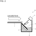
- FIG. 2 is a schematic diagram illustrating a contaminant detector 10 according to Embodiment 1.
- the first heat exchanger 108 includes a drain pan 1 and a drainage unit 6.
- the drain pan 1, to which water 5 is discharged, is a sump that receives water droplets or the discharged water 5.
- the drain pan 1 tends to have a gently sloping surface extending to the drainage unit 6. Such a surface facilitates the flow of the discharged water 5 to the drainage unit 6.
- the drainage unit 6, which accumulates discharged water from the drain pan 1, is a drainage channel, for example.
- the drainage unit 6 is a place to temporarily accumulate water droplets or the discharged water 5 until the water flows downstream.
- the drainage unit 6 may have a hollow to temporarily retain the water 5.
- the water 5 accumulated in the drainage unit 6 is discharged to the outside, for example, through a drainage pipe (not illustrated) or by a drainage pump (not illustrated).
- the drainage unit 6 is likely to be contaminated because of long exposure to the accumulated water 5.
- the drainage pipe or the drainage pump may be clogged with contaminants 4.
- the water 5 accumulated in the drainage unit 6 may fail to be discharged, resulting in an increase in water level in the drainage unit 6. If the accumulated water 5 is contaminated by the contaminants 4, the water 5 may have an unevenly colored, translucent appearance.
- the contaminants 4 include contamination with microorganisms.
- the contaminants 4 are not limited to contamination with microorganisms.
- the contaminants 4 may have a translucent appearance.
- the term "contamination with microorganisms" as used herein refers to a combination of dirt components in the air and mucilaginous polysaccharides metabolized by, for example, bacteria or mold. Contamination with microorganisms include contamination by a viscous aggregate called a biofilm or a slime.
- the contaminants 4 containing microorganisms can encourage the growth of bacteria or mold that is hazardous to humans, and pose a pathogenic risk when dispersed in the air. Therefore, for example, an air-conditioning apparatus, which is a target of legal inspection under the Act on Maintenance of Sanitation in Buildings, needs to be subjected to periodic inspection.
- the contaminant detector 10 which detects a state of contamination by the contaminants 4, includes a detection object 2 and a detection unit 3.
- the contaminant detector 10 is used in the air-conditioning apparatus, serving as the refrigeration cycle apparatus 100.
- the contaminant detector 10 can be used in, for example, an industrial plant, a drainage channel around a water supply system, and an apparatus including a drainage channel.
- the detection object 2 is a flat or plate-shaped part that is inclined relative to the horizontal direction in the drainage unit 6 and on which the contaminants 4 can be deposited.
- the angle of inclination is not limited to any angle.
- the detection object 2 is preferably inclined from the drain pan 1 toward the bottom of the drainage unit 6 so that the detection object 2 can be contaminated by water droplets or the discharged water 5.
- the water droplets or discharged water 5 flows on the detection object 2.
- the detection object 2 is located downstream in a flow direction of the water 5 in the drainage unit 6.
- the detection object 2 is joined at at least one point to the drainage unit 6. This eliminates the likelihood that the detection object 2 may interfere with accumulation of the water 5.
- the detection object 2 preferably defines a space with a side or the bottom of the drainage unit 6 so that the entire bottom of the drainage unit 6 is not covered with the detection object 2.
- the detection object 2 is preferably made of a material that can be contaminated to the same extent as that to which the drainage unit 6 is contaminated.
- the detection object 2 may be made of the same material as that of the drainage unit 6.
- the detection object 2 may be contaminated to the same extent as that to which the drainage unit is contaminated by changing the surface roughness, hydrophilicity, and other properties of the detection object 2.
- the detection object 2, which is disposed in the drainage unit 6, is likely to be contaminated because of long exposure to the water 5 accumulated in the drainage unit 6.
- the detection unit 3 emits energy toward the detection object 2 to detect a contamination state of the detection object 2.
- the detection unit 3 detects whether the contaminants 4 on the detection object 2 in the drainage unit 6 are submerged. Furthermore, the detection unit 3 determines the amount of contamination by the contaminants 4 when detecting the contaminants 4.
- the detection unit 3 is disposed above the drainage unit 6 and faces the detection object 2 in a non-contact manner. The detection unit 3 emits energy toward the detection object 2 and then receives reflected energy.
- the detection unit 3 detects, based on a received signal, whether the detection object 2 is submerged. When the detection object 2 is not submerged, the detection unit 3 detects the presence or absence of contaminants 4 on the detection object 2. Upon detecting the presence of contaminants 4, the detection unit 3 determines the amount of contamination by the contaminants 4. In other words, the detection unit 3 can detect the presence or absence of submersion of the detection object 2, the amount of contamination by the contaminants 4, and the detection object 2 with no contaminants 4. Therefore, the detection unit 3 detects a water level relative to the detection object 2 when it is not clear whether the detection object 2 is submerged, and detects the presence or absence of contamination and the amount of contamination when the detection object 2 is not submerged.
- FIG. 3 is a functional block diagram of the detection unit 3 in Embodiment 1. As illustrated in FIG. 3 , the detection unit 3 includes a transmission and reception module 11, a calculation module 12, and a determination module 13.
- the transmission and reception module 11 emits and receives energy, and is a sensor, for example.
- the transmission and reception module 11 is of a non-contact type.
- Examples of the transmission and reception module 11 include a photoelectric sensor, a capacitive proximity switch, an ultrasonic sensor, a laser Doppler meter, a camera, a charge-coupled device (CCD) image sensor, and a complementary metal-oxide semiconductor (CMOS) image sensor.
- the transmission and reception module 11, which is of the non-contact type, has excellent environmental resistance.
- the calculation module 12 calculates the amount of energy received by the transmission and reception module 11. For example, the calculation module 12 obtains the total amount of received energy or the intensity of reflected energy.
- the determination module 13 determines, based on the amount of energy calculated by the calculation module 12, a contamination state of the detection object 2. Specifically, the determination module 13 determines, based on the amount of energy calculated by the calculation module 12, whether the detection object 2 is submerged. Then, the determination module 13 determines, based on the amount of energy calculated by the calculation module 12, the amount of contaminants 4 deposited on the detection object 2.
- the calculation module 12 and the determination module 13 may be mounted on an electric circuit included in the detection unit 3.
- the detection unit 3 operates at any time.
- the transmission and reception module 11 of the detection unit 3 is an ultrasonic sensor.
- the detection object 2 is made of the same material as that of the drainage unit 6. An upstream portion of the detection object 2 is fixed to the drainage unit 6. An operation of the contaminant detector 10 in a state where the detection object 2 is not submerged and that in a state where the detection object 2 is submerged will be described separately.
- FIG. 4 is a schematic diagram illustrating the contaminant detector 10 according to Embodiment 1 at a low water level. The state where the detection object 2 is not submerged will first be described.
- an open arrow represents a flow direction of the water 5
- solid-line arrows represent energy emitted and received by the detection unit 3.
- water droplets or the discharged water 5 is received by the drain pan 1. Since the drain pan 1 has a gently sloping surface extending to the drainage unit 6, the discharged water 5 smoothly flows to and accumulates in the drainage unit 6.
- the detection object 2 is inclined from the drain pan 1 toward the bottom of the drainage unit 6. Thus, the water droplets or discharged water 5 flows on the detection object 2 and accumulates in the drainage unit 6. Since the water 5 flows on the detection object 2, the contaminants 4, or a combination of dirt components in the air and water, are likely to form on the detection object 2. Therefore, the detection object 2 can be used to simulate contaminants 4 in the drainage unit 6, which is likely to suffer from contamination.
- the detection object 2 When the water 5 is discharged to the outside, for example, through the drainage pipe or by the drainage pump, at a rate higher than a rate at which the water 5 is accumulated, the detection object 2 is not submerged, as illustrated in FIG. 4 .
- the transmission and reception module 11 of the detection unit 3 emits energy toward the detection object 2 and then receives reflected energy.
- the calculation module 12 calculates the amount of received energy.
- the determination module 13 determines, based on the amount of received energy, that the detection object 2 is not submerged. The determination module 13 then determines the amount of contaminants 4 deposited on the detection object 2.
- the transmission and reception module 11 is the ultrasonic sensor.
- the detection unit 3 determines a contamination state by using, as an index, the intensity of a received signal depending on, for example, the extent of attenuation of ultrasonic waves, specular reflection, or non-specular reflection.
- the intensities of received signals have the following relationship: the intensity in a state with no contaminants 4 > the intensity in a state with the contaminants 4 > the intensity in a state where the detection object 2 is submerged.
- the detection unit 3 detects that the detection object 2 is not submerged, and detects the presence or absence of contaminants 4 on the detection object 2.
- the detection unit 3 also determines the amount of contaminants 4 on the basis of the intensity of a received signal. In this case, the detection unit 3 performs detection based on a received signal that depends on the extent of attenuation of ultrasonic waves. If the contaminants 4 are translucent, the detection unit 3 can detect the contaminants 4. Furthermore, if the accumulated water 5 is contaminated and has an unevenly colored or translucent appearance, the detection object 2 can detect the presence or absence of submersion of the detection object 2.
- FIG. 5 is a schematic diagram illustrating the contaminant detector 10 according to Embodiment 1 at a high water level.
- an open arrow represents the flow direction of the water 5
- solid-line arrows represent energy emitted and received by the detection unit 3.
- the transmission and reception module 11 of the detection unit 3 emits energy toward the detection object 2 and then receives reflected energy.
- the calculation module 12 calculates the amount of received energy.
- the determination module 13 determines, based on the amount of received energy, that the detection object 2 is submerged. If the detection object 2 is located in an upper portion of the drainage unit 6, the detection unit 3 can detect a high water level in the drainage unit 6.
- the detection object 2 on which the contaminants 4 can be deposited is inclined relative to the horizontal direction.
- the detection unit 3 detects the height of a portion of the inclined detection object 2 that is located in the water 5 to determine whether the detection object 2 is submerged.
- the determination module 13 of the detection unit 3 determines a contamination state of the detection object 2. As described above, the contamination state can be detected even in the presence of the water 5.
- the contaminants 4 include a contamination state with microorganisms.
- the contaminant detector 10 according to Embodiment 1 may be an alternative to legal inspection under the Act on Maintenance of Sanitation in Buildings. Since the detection unit 3 receives a signal reflected from the detection object 2 to detect a contamination state, the appearance of the accumulated water 5 hardly interferes with detection. Furthermore, the operation timing of the detection unit 3 is not limited to timing after a drainage process. Since the detection unit 3 can operate at any time, the amount of contaminants 4 can be detected before a water level in the drainage unit 6 is abnormally high due to the contaminants 4 blocking the drainage pipe or the drainage pump.
- a contamination state can be detected in the above-described manner before the occurrence of an abnormal state where the water level is abnormally high.
- the drain pan 1 to receive discharged water is a target of legal inspection under the Act on Maintenance of Sanitation in Buildings and is subjected to periodic inspection.
- the air-conditioning apparatus typically needs to be disassembled, which is laborious and costly.
- the contaminant detector 10 according to Embodiment 1 can detect the presence or absence of contaminants 4 without the need for disassembly of the air-conditioning apparatus. This results in a reduction in time, effort, and cost.
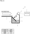
- FIG. 6 is a schematic diagram illustrating a contaminant detector 10 according to Embodiment 2.
- Embodiment 2 differs from Embodiment 1 in that the contaminant detector includes a notification unit 7.
- parts that are common to Embodiment 1 are designated by the same reference signs, and description thereof is omitted. The following description will focus on the difference between Embodiments 1 and 2.
- the notification unit 7 is connected to the detection unit 3, and provides notification of a contamination state detected by the detection unit 3.
- the notification unit 7 provides notification that, for example, cleaning and maintenance are required because of submersion of the drainage unit 6 or contamination of the drainage unit 6 by the contaminants 4.
- the notification unit 7 includes a light, an electronic notice board, buzzer sound, and a network.
- the notification unit 7 provides notifications associated with detection results of the detection unit 3, and the detection results show a small amount of contaminants 4, a large amount of contaminants 4, and submersion of the drainage unit 6.
- the notification unit 7 may include a storage medium to store the detection results of the detection unit 3 and a microcomputer to check the stored detection results. In this case, if a detection result showing submersion of the drainage unit 6 is obtained, the notification unit 7 can provide, by using the storage medium, notification of the submersion as long as the preceding detection result shows a large amount of contaminants 4.
- the contaminant detector 10 further includes the notification unit 7 to provide notification of a contamination state detected by the detection unit 3.
- the notification unit 7 provides notification of the need for, for example, cleaning and maintenance, in each of the case where the drainage unit 6 is submerged and the case where the amount of contaminants 4 is large.
- the drain pan 1 to receive discharged water is a target of legal inspection under the Act on Maintenance of Sanitation in Buildings and is subjected to periodic inspection.
- the air-conditioning apparatus typically needs to be disassembled, which is laborious and costly.
- the contaminant detector 10 according to Embodiment 1 includes the notification unit 7 and provides notification of the presence or absence of contaminants 4 without the need for disassembly of the air-conditioning apparatus. Therefore, the contaminant detector 10 can prompt a user to perform, for example, cleaning and maintenance.
- FIG. 7 is a schematic diagram illustrating a contaminant detector 10 according to Embodiment 3.
- Embodiment 3 differs from Embodiments 1 and 2 in the operation timing of the detection unit 3.
- parts that are common to Embodiments 1 and 2 are designated by the same reference signs, and description thereof is omitted. The following description will focus on the difference between Embodiment 3 and Embodiments 1 and 2.
- the controller 9 is connected to the detection unit 3, and causes the detection unit 3 to operate at predetermined operation timing.
- the refrigeration cycle apparatus 100 has operation steps including the start of operation, a steady state operation, a drainage process, a drying process, and the stop of operation.
- the controller 9 causes the detection unit 3 to operate at a time determined for each of the operation steps.
- the controller 9 causes the detection unit 3 to operate at any timing.
- the controller 9 causes the detection unit 3 to operate at a predetermined time for each of the operation steps, for example, A minutes after the start of operation, every B minutes during the steady state operation, C minutes after the drainage process, every D minutes during the drying process, and E minutes after the stop of operation.
- the controller 9 causes the detection unit 3 to operate every D minutes.
- the controller 9 again causes the detection unit 3 to operate every B minutes.
- the controller 9 causes the detection unit 3 to operate E minutes after the stop of operation of the refrigeration cycle apparatus 100.
- the refrigeration cycle apparatus further includes the controller 9 that causes the detection unit 3 to operate at a time determined for each of the operation steps including the start of operation, the steady state operation, the drainage process, the drying process, and the stop of operation.
- the controller 9 that causes the detection unit 3 to operate at a time determined for each of the operation steps including the start of operation, the steady state operation, the drainage process, the drying process, and the stop of operation.
- detection of the presence or absence of contaminants 4 and detection of whether the drainage unit 6 is submerged are performed not only at completion of the drainage process but also at each of the operation steps, such as the start of operation, the steady state operation, the drying process, and the stop of operation.
Landscapes
- Engineering & Computer Science (AREA)
- Chemical & Material Sciences (AREA)
- Combustion & Propulsion (AREA)
- Mechanical Engineering (AREA)
- General Engineering & Computer Science (AREA)
- Life Sciences & Earth Sciences (AREA)
- Environmental & Geological Engineering (AREA)
- Ecology (AREA)
- Biodiversity & Conservation Biology (AREA)
- Environmental Sciences (AREA)
- Physics & Mathematics (AREA)
- Health & Medical Sciences (AREA)
- Analytical Chemistry (AREA)
- Biochemistry (AREA)
- General Health & Medical Sciences (AREA)
- General Physics & Mathematics (AREA)
- Immunology (AREA)
- Pathology (AREA)
- Air Conditioning Control Device (AREA)
Abstract
Description
- The present invention relates to a contaminant detector that detects a state of contamination by contaminants and a refrigeration cycle apparatus.
- A known contaminant detector detects a state of contamination by contaminants. Examples of contaminants in the presence of water include biofilms. The term "biofilm" as used herein refers to a semisolid slimy layer of microorganisms growing in water accumulated in a sump or a drainage channel. Biofilms are hygienically undesirable. A biofilm may block, for example, a discharge port through which accumulated water is discharged to a drainage channel.
Patent Literature 1 discloses an air-conditioning apparatus including a drain pan to receive water, a discharge unit to discharge water received by the drain pan, and a detection unit to detect a biofilm as contaminants that form on the drain pan. The detection unit inPatent Literature 1 detects a biofilm after completion of a step of discharging water from the drain pan. - Patent Literature 1: Japanese Patent
JP 6 188 994 B2 - In the air-conditioning apparatus disclosed in
Patent Literature 1, a contamination state cannot be detected until the water discharging step is completed. For example, a sump or a drainage channel tends to have water. This leads to demands for devices capable of detecting a contamination state in the presence of water. - In response to the above issue, it is an object of the present invention to provide a contaminant detector that detects a contamination state even in the presence of water and a refrigeration cycle apparatus.
- A contaminant detector according to an embodiment of the present invention includes a detection object that is inclined relative to a horizontal direction in a drainage unit for accumulation of discharged water and on which a contaminant is to be deposited, and a detection unit configured to emit energy toward the detection object to detect a contamination state of the detection object.
- The detection unit includes a transmission and reception module configured to emit and receive energy, a calculation module configured to calculate an amount of energy received from the detection object by the transmission and reception module, and a determination module configured to determine, based on the amount of energy calculated by the calculation module, the contamination state of the detection object.
- In the embodiment of the present invention, the detection object on which a contaminant is to be deposited is inclined relative to the horizontal direction. In the case where the detection object is located in water, the detection unit detects the height of a portion of the inclined detection object that is located in the water and determines whether the detection object is submerged. In the case where the detection object is not submerged, the determination module of the detection unit determines a contamination state of the detection object. As described above, the contamination state can be detected even in the presence of water.
-
-
FIG. 1 is a circuit diagram illustrating a refrigeration cycle apparatus inEmbodiment 1. -
FIG. 2 is a schematic diagram illustrating a contaminant detector according toEmbodiment 1. -
FIG. 3 is a functional block diagram of a detection unit inEmbodiment 1. -
FIG. 4 is a schematic diagram illustrating the contaminant detector according toEmbodiment 1 at a low water level. -
FIG. 5 is a schematic diagram illustrating the contaminant detector according toEmbodiment 1 at a high water level. -
FIG. 6 is a schematic diagram illustrating a contaminant detector according toEmbodiment 2. -
FIG. 7 is a schematic diagram illustrating a contaminant detector according toEmbodiment 3. - Contaminant detectors and refrigeration cycle apparatuses according to embodiments of the present invention will be described below with reference to the drawings. Note that the embodiments should not be construed as limiting the present invention. Furthermore, note that the relationship between the sizes of components in the following figures including
FIG. 1 may differ from that of actual ones. For the sake of understanding the present invention, terms representing directions will be used as appropriate. These terms are used herein only for the purpose of description of the present invention, and should not be construed as limiting the present invention. Examples of the terms representing directions include "upper", "lower", "right", "left", "front", and "rear". -
FIG. 1 is a circuit diagram illustrating arefrigeration cycle apparatus 100 inEmbodiment 1. Therefrigeration cycle apparatus 100 is, for example, an air-conditioning apparatus that conditions air in an indoor space. As illustrated inFIG. 1 , therefrigeration cycle apparatus 100 includes anoutdoor unit 102, anindoor unit 103, and acontroller 9. Theoutdoor unit 102 includes acompressor 106, aflow switching device 107, afirst heat exchanger 108, an outdoor fan 109, and anexpansion unit 110. Theindoor unit 103 includes asecond heat exchanger 111 and anindoor fan 112. Therefrigeration cycle apparatus 100 is not limited to an air-conditioning apparatus, and may be a refrigeration apparatus. - The
compressor 106, theflow switching device 107, thefirst heat exchanger 108, theexpansion unit 110, and thesecond heat exchanger 111 are connected byrefrigerant pipes 105, thus forming arefrigerant circuit 104. Thecompressor 106 sucks low-temperature, low-pressure refrigerant, compresses the sucked refrigerant into high-temperature, high-pressure refrigerant, and discharges the compressed refrigerant. Thecompressor 106 is, for example, a capacity-controllable inverter compressor. Theflow switching device 107, which switches between refrigerant flow directions in therefrigerant circuit 104, is a four-way valve, for example. Thefirst heat exchanger 108 exchanges heat between, for example, the refrigerant and outdoor air. Thefirst heat exchanger 108 operates as a condenser in a cooling operation, and operates as an evaporator in a heating operation. Theexpansion unit 110 is a pressure reducing valve or expansion valve that reduces the pressure of refrigerant to expand the refrigerant. Theexpansion unit 110 is, for example, an electronic expansion valve having an adjustable opening degree. - The second heat exchanger 111 exchanges heat between, for example, the refrigerant and indoor air. The
second heat exchanger 111 operates as an evaporator in the cooling operation, and operates as a condenser in the heating operation. Theindoor fan 112 is a device that sends the indoor air to thesecond heat exchanger 111. - Operation modes of the
refrigeration cycle apparatus 100 will now be described. The cooling operation will first be described. In the cooling operation, the refrigerant sucked by thecompressor 106 is compressed into high-temperature, high-pressure gaseous refrigerant and is then discharged by thecompressor 106. The high-temperature, high-pressure gaseous refrigerant discharged from thecompressor 106 passes through theflow switching device 107 and flows into thefirst heat exchanger 108, serving as a condenser. In thefirst heat exchanger 108, the refrigerant exchanges heat with the outdoor air sent by the outdoor fan 109 and thus condenses and liquifies. The condensed liquid refrigerant flows into theexpansion unit 110. In theexpansion unit 110, the refrigerant is expanded and reduced in pressure, and thus turns into refrigerant in a low-temperature, low-pressure, two-phase gas-liquid state. The refrigerant in the two-phase gas-liquid state flows into thesecond heat exchanger 111, serving as an evaporator. In thesecond heat exchanger 111, the refrigerant exchanges heat with the indoor air sent by theindoor fan 112, and thus evaporates and gasifies. At this time, the indoor air is cooled, thus cooling the indoor space. The evaporated, low-temperature, low-pressure gaseous refrigerant passes through theflow switching device 107 and is then sucked into thecompressor 106. - The heating operation will now be described. In the heating operation, the refrigerant sucked by the
compressor 106 is compressed into high-temperature, high-pressure gaseous refrigerant and is then discharged by thecompressor 106. The high-temperature, high-pressure gaseous refrigerant discharged from thecompressor 106 passes through theflow switching device 107 and flows into thesecond heat exchanger 111, serving as a condenser. In thesecond heat exchanger 111, the refrigerant exchanges heat with the indoor air sent by theindoor fan 112, and thus condenses and liquifies. At this time, the indoor air is heated, thus heating the indoor space. The condensed liquid refrigerant flows into theexpansion unit 110. In theexpansion unit 110, the refrigerant is expanded and reduced in pressure, and thus turns into refrigerant in the low-temperature, low-pressure two-phase gas-liquid state. The refrigerant in the two-phase gas-liquid state flows into thefirst heat exchanger 108, serving as an evaporator. In thefirst heat exchanger 108, the refrigerant exchanges heat with the outdoor air sent by the outdoor fan 109, and thus evaporates and gasifies. The evaporated, low-temperature, low-pressure gaseous refrigerant passes through theflow switching device 107 and is then sucked into thecompressor 106. - The
refrigeration cycle apparatus 100 may exclude theflow switching device 107. In this case, therefrigeration cycle apparatus 100 is a dedicated cooling apparatus or a dedicated heating apparatus. - The
controller 9 is configured as dedicated hardware or a central processing unit (CPU) (also called a processing unit, an arithmetic unit, a microprocessor, a microcomputer, or a processor) that runs a program stored in a storage device. In the case where thecontroller 9 is dedicated hardware, thecontroller 9 corresponds to, for example, a single circuit, a composite circuit, an application specific integrated circuit (ASIC), a field-programmable gate array (FPGA), or a combination thereof. Functional parts that thecontroller 9 implements may be implemented by individual hardware components or may be implemented by a single hardware component. - In the case where the
controller 9 is a CPU, functions that thecontroller 9 performs are implemented by software, firmware, or a combination of software and firmware. Software and firmware are described as programs. The CPU reads and runs the programs, thus implementing the functions. A subset of the functions of thecontroller 9 may be implemented by dedicated hardware, and another subset thereof may be implemented by software or firmware. -
FIG. 2 is a schematic diagram illustrating acontaminant detector 10 according toEmbodiment 1. As illustrated inFIG. 2 , thefirst heat exchanger 108 includes adrain pan 1 and adrainage unit 6. - The
drain pan 1, to whichwater 5 is discharged, is a sump that receives water droplets or the dischargedwater 5. Thedrain pan 1 tends to have a gently sloping surface extending to thedrainage unit 6. Such a surface facilitates the flow of the dischargedwater 5 to thedrainage unit 6. - The
drainage unit 6, which accumulates discharged water from thedrain pan 1, is a drainage channel, for example. Thedrainage unit 6 is a place to temporarily accumulate water droplets or the dischargedwater 5 until the water flows downstream. Thedrainage unit 6 may have a hollow to temporarily retain thewater 5. Thewater 5 accumulated in thedrainage unit 6 is discharged to the outside, for example, through a drainage pipe (not illustrated) or by a drainage pump (not illustrated). Thedrainage unit 6 is likely to be contaminated because of long exposure to the accumulatedwater 5. For example, the drainage pipe or the drainage pump may be clogged withcontaminants 4. Thus, thewater 5 accumulated in thedrainage unit 6 may fail to be discharged, resulting in an increase in water level in thedrainage unit 6. If the accumulatedwater 5 is contaminated by thecontaminants 4, thewater 5 may have an unevenly colored, translucent appearance. - The
contaminants 4 include contamination with microorganisms. Thecontaminants 4 are not limited to contamination with microorganisms. Thecontaminants 4 may have a translucent appearance. The term "contamination with microorganisms" as used herein refers to a combination of dirt components in the air and mucilaginous polysaccharides metabolized by, for example, bacteria or mold. Contamination with microorganisms include contamination by a viscous aggregate called a biofilm or a slime. Thecontaminants 4 containing microorganisms can encourage the growth of bacteria or mold that is hazardous to humans, and pose a pathogenic risk when dispersed in the air. Therefore, for example, an air-conditioning apparatus, which is a target of legal inspection under the Act on Maintenance of Sanitation in Buildings, needs to be subjected to periodic inspection. - As illustrated in
FIG. 2 , thecontaminant detector 10, which detects a state of contamination by thecontaminants 4, includes adetection object 2 and adetection unit 3. InEmbodiment 1, thecontaminant detector 10 is used in the air-conditioning apparatus, serving as therefrigeration cycle apparatus 100. Thecontaminant detector 10 can be used in, for example, an industrial plant, a drainage channel around a water supply system, and an apparatus including a drainage channel. - The
detection object 2 is a flat or plate-shaped part that is inclined relative to the horizontal direction in thedrainage unit 6 and on which thecontaminants 4 can be deposited. The larger the angle of inclination of thedetection object 2 relative to the horizontal direction is, the more preferable it is. The angle of inclination is not limited to any angle. Thedetection object 2 is preferably inclined from thedrain pan 1 toward the bottom of thedrainage unit 6 so that thedetection object 2 can be contaminated by water droplets or the dischargedwater 5. Thus, the water droplets or dischargedwater 5 flows on thedetection object 2. In other words, thedetection object 2 is located downstream in a flow direction of thewater 5 in thedrainage unit 6. Thedetection object 2 is joined at at least one point to thedrainage unit 6. This eliminates the likelihood that thedetection object 2 may interfere with accumulation of thewater 5. - The
detection object 2 preferably defines a space with a side or the bottom of thedrainage unit 6 so that the entire bottom of thedrainage unit 6 is not covered with thedetection object 2. Thedetection object 2 is preferably made of a material that can be contaminated to the same extent as that to which thedrainage unit 6 is contaminated. For example, thedetection object 2 may be made of the same material as that of thedrainage unit 6. Thedetection object 2 may be contaminated to the same extent as that to which the drainage unit is contaminated by changing the surface roughness, hydrophilicity, and other properties of thedetection object 2. Like thedrainage unit 6, thedetection object 2, which is disposed in thedrainage unit 6, is likely to be contaminated because of long exposure to thewater 5 accumulated in thedrainage unit 6. - The
detection unit 3 emits energy toward thedetection object 2 to detect a contamination state of thedetection object 2. Thedetection unit 3 detects whether thecontaminants 4 on thedetection object 2 in thedrainage unit 6 are submerged. Furthermore, thedetection unit 3 determines the amount of contamination by thecontaminants 4 when detecting thecontaminants 4. Thedetection unit 3 is disposed above thedrainage unit 6 and faces thedetection object 2 in a non-contact manner. Thedetection unit 3 emits energy toward thedetection object 2 and then receives reflected energy. - The
detection unit 3 detects, based on a received signal, whether thedetection object 2 is submerged. When thedetection object 2 is not submerged, thedetection unit 3 detects the presence or absence ofcontaminants 4 on thedetection object 2. Upon detecting the presence ofcontaminants 4, thedetection unit 3 determines the amount of contamination by thecontaminants 4. In other words, thedetection unit 3 can detect the presence or absence of submersion of thedetection object 2, the amount of contamination by thecontaminants 4, and thedetection object 2 with nocontaminants 4. Therefore, thedetection unit 3 detects a water level relative to thedetection object 2 when it is not clear whether thedetection object 2 is submerged, and detects the presence or absence of contamination and the amount of contamination when thedetection object 2 is not submerged. -
FIG. 3 is a functional block diagram of thedetection unit 3 inEmbodiment 1. As illustrated inFIG. 3 , thedetection unit 3 includes a transmission andreception module 11, acalculation module 12, and adetermination module 13. - The transmission and
reception module 11 emits and receives energy, and is a sensor, for example. The transmission andreception module 11 is of a non-contact type. Examples of the transmission andreception module 11 include a photoelectric sensor, a capacitive proximity switch, an ultrasonic sensor, a laser Doppler meter, a camera, a charge-coupled device (CCD) image sensor, and a complementary metal-oxide semiconductor (CMOS) image sensor. The transmission andreception module 11, which is of the non-contact type, has excellent environmental resistance. - The
calculation module 12 calculates the amount of energy received by the transmission andreception module 11. For example, thecalculation module 12 obtains the total amount of received energy or the intensity of reflected energy. - The
determination module 13 determines, based on the amount of energy calculated by thecalculation module 12, a contamination state of thedetection object 2. Specifically, thedetermination module 13 determines, based on the amount of energy calculated by thecalculation module 12, whether thedetection object 2 is submerged. Then, thedetermination module 13 determines, based on the amount of energy calculated by thecalculation module 12, the amount ofcontaminants 4 deposited on thedetection object 2. Thecalculation module 12 and thedetermination module 13 may be mounted on an electric circuit included in thedetection unit 3. - Operations of the
contaminant detector 10 will now be described. InEmbodiment 1, thedetection unit 3 operates at any time. The transmission andreception module 11 of thedetection unit 3 is an ultrasonic sensor. Thedetection object 2 is made of the same material as that of thedrainage unit 6. An upstream portion of thedetection object 2 is fixed to thedrainage unit 6. An operation of thecontaminant detector 10 in a state where thedetection object 2 is not submerged and that in a state where thedetection object 2 is submerged will be described separately. -
FIG. 4 is a schematic diagram illustrating thecontaminant detector 10 according toEmbodiment 1 at a low water level. The state where thedetection object 2 is not submerged will first be described. InFIG. 4 , an open arrow represents a flow direction of thewater 5, and solid-line arrows represent energy emitted and received by thedetection unit 3. As illustrated inFIG. 4 , water droplets or the dischargedwater 5 is received by thedrain pan 1. Since thedrain pan 1 has a gently sloping surface extending to thedrainage unit 6, the dischargedwater 5 smoothly flows to and accumulates in thedrainage unit 6. Thedetection object 2 is inclined from thedrain pan 1 toward the bottom of thedrainage unit 6. Thus, the water droplets or dischargedwater 5 flows on thedetection object 2 and accumulates in thedrainage unit 6. Since thewater 5 flows on thedetection object 2, thecontaminants 4, or a combination of dirt components in the air and water, are likely to form on thedetection object 2. Therefore, thedetection object 2 can be used to simulatecontaminants 4 in thedrainage unit 6, which is likely to suffer from contamination. - When the
water 5 is discharged to the outside, for example, through the drainage pipe or by the drainage pump, at a rate higher than a rate at which thewater 5 is accumulated, thedetection object 2 is not submerged, as illustrated inFIG. 4 . The transmission andreception module 11 of thedetection unit 3 emits energy toward thedetection object 2 and then receives reflected energy. Thecalculation module 12 calculates the amount of received energy. Thedetermination module 13 determines, based on the amount of received energy, that thedetection object 2 is not submerged. Thedetermination module 13 then determines the amount ofcontaminants 4 deposited on thedetection object 2. - In
Embodiment 1, the transmission andreception module 11 is the ultrasonic sensor. In this case, thedetection unit 3 determines a contamination state by using, as an index, the intensity of a received signal depending on, for example, the extent of attenuation of ultrasonic waves, specular reflection, or non-specular reflection. The intensities of received signals have the following relationship: the intensity in a state with nocontaminants 4 > the intensity in a state with thecontaminants 4 > the intensity in a state where thedetection object 2 is submerged. - As described above, the
detection unit 3 detects that thedetection object 2 is not submerged, and detects the presence or absence ofcontaminants 4 on thedetection object 2. Thedetection unit 3 also determines the amount ofcontaminants 4 on the basis of the intensity of a received signal. In this case, thedetection unit 3 performs detection based on a received signal that depends on the extent of attenuation of ultrasonic waves. If thecontaminants 4 are translucent, thedetection unit 3 can detect thecontaminants 4. Furthermore, if the accumulatedwater 5 is contaminated and has an unevenly colored or translucent appearance, thedetection object 2 can detect the presence or absence of submersion of thedetection object 2. -
FIG. 5 is a schematic diagram illustrating thecontaminant detector 10 according toEmbodiment 1 at a high water level. The state where thedetection object 2 is submerged will now be described. InFIG. 5 , an open arrow represents the flow direction of thewater 5, and solid-line arrows represent energy emitted and received by thedetection unit 3. When thewater 5 is discharged to the outside, for example, through the drainage pipe or by the drainage pump, at a rate lower than a rate at which thewater 5 is accumulated, thedetection object 2 is submerged, as illustrated inFIG. 5 . The transmission andreception module 11 of thedetection unit 3 emits energy toward thedetection object 2 and then receives reflected energy. Thecalculation module 12 calculates the amount of received energy. Thedetermination module 13 determines, based on the amount of received energy, that thedetection object 2 is submerged. If thedetection object 2 is located in an upper portion of thedrainage unit 6, thedetection unit 3 can detect a high water level in thedrainage unit 6. - In
Embodiment 1, thedetection object 2 on which thecontaminants 4 can be deposited is inclined relative to the horizontal direction. When thedetection object 2 is located in thewater 5, thedetection unit 3 detects the height of a portion of theinclined detection object 2 that is located in thewater 5 to determine whether thedetection object 2 is submerged. When thedetection object 2 is not submerged, thedetermination module 13 of thedetection unit 3 determines a contamination state of thedetection object 2. As described above, the contamination state can be detected even in the presence of thewater 5. - The
contaminants 4 include a contamination state with microorganisms. Thecontaminant detector 10 according toEmbodiment 1 may be an alternative to legal inspection under the Act on Maintenance of Sanitation in Buildings. Since thedetection unit 3 receives a signal reflected from thedetection object 2 to detect a contamination state, the appearance of the accumulatedwater 5 hardly interferes with detection. Furthermore, the operation timing of thedetection unit 3 is not limited to timing after a drainage process. Since thedetection unit 3 can operate at any time, the amount ofcontaminants 4 can be detected before a water level in thedrainage unit 6 is abnormally high due to thecontaminants 4 blocking the drainage pipe or the drainage pump. - In
Embodiment 1, a contamination state can be detected in the above-described manner before the occurrence of an abnormal state where the water level is abnormally high. In the case where therefrigeration cycle apparatus 100 is an air-conditioning apparatus, thedrain pan 1 to receive discharged water is a target of legal inspection under the Act on Maintenance of Sanitation in Buildings and is subjected to periodic inspection. In periodic inspection, the air-conditioning apparatus typically needs to be disassembled, which is laborious and costly. In contrast, thecontaminant detector 10 according toEmbodiment 1 can detect the presence or absence ofcontaminants 4 without the need for disassembly of the air-conditioning apparatus. This results in a reduction in time, effort, and cost. -
FIG. 6 is a schematic diagram illustrating acontaminant detector 10 according toEmbodiment 2.Embodiment 2 differs fromEmbodiment 1 in that the contaminant detector includes anotification unit 7. InEmbodiment 2, parts that are common toEmbodiment 1 are designated by the same reference signs, and description thereof is omitted. The following description will focus on the difference betweenEmbodiments - As illustrated in
FIG. 6 , thenotification unit 7 is connected to thedetection unit 3, and provides notification of a contamination state detected by thedetection unit 3. Thenotification unit 7 provides notification that, for example, cleaning and maintenance are required because of submersion of thedrainage unit 6 or contamination of thedrainage unit 6 by thecontaminants 4. Thenotification unit 7 includes a light, an electronic notice board, buzzer sound, and a network. Thenotification unit 7 provides notifications associated with detection results of thedetection unit 3, and the detection results show a small amount ofcontaminants 4, a large amount ofcontaminants 4, and submersion of thedrainage unit 6. Thenotification unit 7 may include a storage medium to store the detection results of thedetection unit 3 and a microcomputer to check the stored detection results. In this case, if a detection result showing submersion of thedrainage unit 6 is obtained, thenotification unit 7 can provide, by using the storage medium, notification of the submersion as long as the preceding detection result shows a large amount ofcontaminants 4. - In
Embodiment 2, thecontaminant detector 10 further includes thenotification unit 7 to provide notification of a contamination state detected by thedetection unit 3. Thenotification unit 7 provides notification of the need for, for example, cleaning and maintenance, in each of the case where thedrainage unit 6 is submerged and the case where the amount ofcontaminants 4 is large. Thus, good sanitary conditions of thedrain pan 1 can be maintained, and a reduction in time, effort, and cost for inspection can be achieved. - In the case where the
refrigeration cycle apparatus 100 is an air-conditioning apparatus, thedrain pan 1 to receive discharged water is a target of legal inspection under the Act on Maintenance of Sanitation in Buildings and is subjected to periodic inspection. In periodic inspection, the air-conditioning apparatus typically needs to be disassembled, which is laborious and costly. In contrast, thecontaminant detector 10 according toEmbodiment 1 includes thenotification unit 7 and provides notification of the presence or absence ofcontaminants 4 without the need for disassembly of the air-conditioning apparatus. Therefore, thecontaminant detector 10 can prompt a user to perform, for example, cleaning and maintenance. -
Embodiment 3. -
FIG. 7 is a schematic diagram illustrating acontaminant detector 10 according toEmbodiment 3.Embodiment 3 differs fromEmbodiments detection unit 3. InEmbodiment 3, parts that are common toEmbodiments Embodiment 3 and Embodiments 1 and 2. - As illustrated in
FIG. 7 , thecontroller 9 is connected to thedetection unit 3, and causes thedetection unit 3 to operate at predetermined operation timing. Therefrigeration cycle apparatus 100 has operation steps including the start of operation, a steady state operation, a drainage process, a drying process, and the stop of operation. Thecontroller 9 causes thedetection unit 3 to operate at a time determined for each of the operation steps. Thecontroller 9 causes thedetection unit 3 to operate at any timing. Thecontroller 9 causes thedetection unit 3 to operate at a predetermined time for each of the operation steps, for example, A minutes after the start of operation, every B minutes during the steady state operation, C minutes after the drainage process, every D minutes during the drying process, and E minutes after the stop of operation. - In the case where the drying process is performed during the steady state operation of the
refrigeration cycle apparatus 100, thecontroller 9 causes thedetection unit 3 to operate every D minutes. When therefrigeration cycle apparatus 100 is returned to the steady state operation at completion of the drainage process and the drying process, thecontroller 9 again causes thedetection unit 3 to operate every B minutes. Thecontroller 9 causes thedetection unit 3 to operate E minutes after the stop of operation of therefrigeration cycle apparatus 100. - In
Embodiment 3, the refrigeration cycle apparatus further includes thecontroller 9 that causes thedetection unit 3 to operate at a time determined for each of the operation steps including the start of operation, the steady state operation, the drainage process, the drying process, and the stop of operation. As described above, for example, detection of the presence or absence ofcontaminants 4 and detection of whether thedrainage unit 6 is submerged are performed not only at completion of the drainage process but also at each of the operation steps, such as the start of operation, the steady state operation, the drying process, and the stop of operation. -
- 1: drain pan,
- 2: detection object,
- 3: detection unit,
- 4: contaminants,
- 5: water,
- 6: drainage unit,
- 7: notification unit,
- 9: controller,
- 10: contaminant detector,
- 11: transmission and reception module,
- 12: calculation module,
- 13: determination module,
- 100: refrigeration cycle apparatus,
- 102: outdoor unit,
- 103: indoor unit,
- 104: refrigerant circuit,
- 105: refrigerant pipe,
- 106: compressor,
- 107: flow switching device,
- 108: first heat exchanger,
- 109: outdoor fan,
- 110: expansion unit,
- 111: second heat exchanger,
- 112: indoor fan
Claims (9)
- A contaminant detector comprising:a detection object that is inclined relative to a horizontal direction in a drainage unit for accumulation of discharged water and on which a contaminant is to be deposited; anda detection unit configured to emit energy toward the detection object to detect a contamination state of the detection object,the detection unit includinga transmission and reception module configured to emit and receive energy,a calculation module configured to calculate an amount of energy received from the detection object by the transmission and reception module, anda determination module configured to determine, based on the amount of energy calculated by the calculation module, the contamination state of the detection object.
- The contaminant detector of claim 1,
wherein the determination module is configured to determine, based on the amount of energy calculated by the calculation module, whether the detection object is submerged. - The contaminant detector of claim 1 or 2,
wherein the determination module is configured to determine, based on the amount of energy calculated by the calculation module, an amount of the contaminant deposited on the detection object. - The contaminant detector of any one of claims 1 to 3,
wherein the detection unit is of a non-contact type. - The contaminant detector of any one of claims 1 to 4,
wherein the contamination state includes contamination with microorganisms. - The contaminant detector of any one of claims 1 to 5,
further comprising:
a notification unit configured to provide notification of the contamination state detected by the detection unit. - The contaminant detector of any one of claims 1 to 6,
wherein the detection object is located downstream in a water flow direction in the drainage unit. - A refrigeration cycle apparatus comprising:a refrigerant circuit in which a compressor, a first heat exchanger, an expansion unit, and a second heat exchanger are connected by refrigerant pipes; andthe contaminant detector of any one of claims 1 to 7,wherein the first heat exchanger includesa drain pan to which water is discharged, andthe drainage unit configured to accumulate discharged water from the drain pan.
- The refrigeration cycle apparatus of claim 8,wherein the refrigeration cycle apparatus has operation steps including a start of operation, a steady state operation, a drainage process, a drying process, and a stop of operation, andwherein the refrigeration cycle apparatus further comprises a controller configured to cause the detection unit to operate at a time determined for each of the operation steps.
Applications Claiming Priority (1)
| Application Number | Priority Date | Filing Date | Title |
|---|---|---|---|
| PCT/JP2021/017025 WO2022230122A1 (en) | 2021-04-28 | 2021-04-28 | Contaminant detection device and refrigeration cycle device |
Publications (3)
| Publication Number | Publication Date |
|---|---|
| EP4317821A1 true EP4317821A1 (en) | 2024-02-07 |
| EP4317821A4 EP4317821A4 (en) | 2024-04-24 |
| EP4317821B1 EP4317821B1 (en) | 2025-12-24 |
Family
ID=82702009
Family Applications (1)
| Application Number | Title | Priority Date | Filing Date |
|---|---|---|---|
| EP21939283.4A Active EP4317821B1 (en) | 2021-04-28 | 2021-04-28 | Contaminant detection device and refrigeration cycle device |
Country Status (5)
| Country | Link |
|---|---|
| US (1) | US12031742B2 (en) |
| EP (1) | EP4317821B1 (en) |
| JP (1) | JP7112810B1 (en) |
| CN (1) | CN117321347B (en) |
| WO (1) | WO2022230122A1 (en) |
Family Cites Families (14)
| Publication number | Priority date | Publication date | Assignee | Title |
|---|---|---|---|---|
| JP2002267514A (en) * | 2001-03-09 | 2002-09-18 | Toto Ltd | Device for detecting flowing state of substance in pipe and system for detecting flowing state of substance in pipe |
| GB2536239B (en) | 2015-03-09 | 2019-03-06 | Jaguar Land Rover Ltd | Windshield monitoring system |
| EP3168604B1 (en) * | 2015-11-10 | 2021-12-01 | LG Electronics Inc. | Device for measuring floating micro-organisms |
| JP6590725B2 (en) | 2016-02-17 | 2019-10-16 | 三菱電機ビルテクノサービス株式会社 | Drain pan contamination detector and air conditioner |
| EP3385635B1 (en) * | 2016-03-03 | 2020-05-06 | Mitsubishi Electric Corporation | Air conditioner |
| ES2911549T3 (en) * | 2017-08-28 | 2022-05-19 | Daikin Ind Ltd | air conditioning device |
| EP3663663B1 (en) * | 2017-08-28 | 2022-05-18 | Daikin Industries, Ltd. | Air processing device |
| CN112272748B (en) * | 2018-06-29 | 2022-09-13 | 三菱电机株式会社 | Air conditioner |
| JP6787421B2 (en) * | 2019-02-26 | 2020-11-18 | ダイキン工業株式会社 | Air treatment equipment |
| JP6944962B2 (en) | 2019-02-27 | 2021-10-06 | ダイキン工業株式会社 | Dirt information estimation system |
| JP6813043B2 (en) * | 2019-02-27 | 2021-01-13 | ダイキン工業株式会社 | Dirt information estimation system |
| JP6891927B2 (en) * | 2019-08-21 | 2021-06-18 | ダイキン工業株式会社 | Air treatment equipment |
| JP6904451B1 (en) * | 2020-03-26 | 2021-07-14 | ダイキン工業株式会社 | Drain pump clogging predictor, air conditioner, and drain pump clogging prediction method |
| GB2599628B (en) * | 2020-09-21 | 2025-04-09 | Charles Austen Pumps Ltd | A liquid filter |
-
2021
- 2021-04-28 CN CN202180097381.8A patent/CN117321347B/en active Active
- 2021-04-28 EP EP21939283.4A patent/EP4317821B1/en active Active
- 2021-04-28 US US18/287,295 patent/US12031742B2/en active Active
- 2021-04-28 WO PCT/JP2021/017025 patent/WO2022230122A1/en not_active Ceased
- 2021-04-28 JP JP2021556276A patent/JP7112810B1/en active Active
Also Published As
| Publication number | Publication date |
|---|---|
| EP4317821A4 (en) | 2024-04-24 |
| JP7112810B1 (en) | 2022-08-04 |
| US20240085053A1 (en) | 2024-03-14 |
| CN117321347B (en) | 2024-04-16 |
| WO2022230122A1 (en) | 2022-11-03 |
| EP4317821B1 (en) | 2025-12-24 |
| US12031742B2 (en) | 2024-07-09 |
| JPWO2022230122A1 (en) | 2022-11-03 |
| CN117321347A (en) | 2023-12-29 |
Similar Documents
| Publication | Publication Date | Title |
|---|---|---|
| JP6440667B2 (en) | Refrigeration cycle equipment | |
| CN107407514B (en) | Air conditioner indoor unit | |
| JP6808075B2 (en) | Air conditioner | |
| JP5800737B2 (en) | Air conditioner indoor unit and air conditioner | |
| CN1705868A (en) | A method and a device for detecting an abnormality of a heat exchanger, and the use of such a device | |
| JPWO2018225257A1 (en) | Equipment using heat pump | |
| EP4317821B1 (en) | Contaminant detection device and refrigeration cycle device | |
| JP4951423B2 (en) | Compressed air dehumidifier | |
| WO2021193903A1 (en) | Drain pump clog prediction device, air conditioner, and drain pump clog prediction method | |
| US10921046B2 (en) | Method for defrosting an evaporator of a sealed system | |
| JP5025381B2 (en) | Drain discharge abnormality detection device and compressed air dehumidification device | |
| JP2016125673A (en) | Refrigeration cycle equipment | |
| JP3448357B2 (en) | Drain water treatment device for air conditioner | |
| JP7520244B1 (en) | Air conditioners | |
| JP7403640B2 (en) | air conditioner | |
| KR20030075391A (en) | Apparatus for alramming over flow of drain pan in air conditioner | |
| WO2022269670A1 (en) | Indoor unit of air conditioning device | |
| JP4879224B2 (en) | Air conditioner, drain water detection method | |
| JP2001255047A (en) | Refrigeration system | |
| JP6843303B1 (en) | Air conditioner | |
| JP2024099241A (en) | Heat exchanger deposit detection system | |
| KR101077537B1 (en) | Condensate Discharge Device of Marine Air Conditioner | |
| WO2024209508A1 (en) | Chilling unit | |
| JPWO2023145016A5 (en) | ||
| JPH09145171A (en) | Air conditioner and accumulator used for it |
Legal Events
| Date | Code | Title | Description |
|---|---|---|---|
| STAA | Information on the status of an ep patent application or granted ep patent |
Free format text: STATUS: THE INTERNATIONAL PUBLICATION HAS BEEN MADE |
|
| PUAI | Public reference made under article 153(3) epc to a published international application that has entered the european phase |
Free format text: ORIGINAL CODE: 0009012 |
|
| STAA | Information on the status of an ep patent application or granted ep patent |
Free format text: STATUS: REQUEST FOR EXAMINATION WAS MADE |
|
| 17P | Request for examination filed |
Effective date: 20231020 |
|
| AK | Designated contracting states |
Kind code of ref document: A1 Designated state(s): AL AT BE BG CH CY CZ DE DK EE ES FI FR GB GR HR HU IE IS IT LI LT LU LV MC MK MT NL NO PL PT RO RS SE SI SK SM TR |
|
| REG | Reference to a national code |
Ref country code: DE Ref legal event code: R079 Ipc: G01N0017000000 Ref country code: DE Ref legal event code: R079 Ref document number: 602021045253 Country of ref document: DE Free format text: PREVIOUS MAIN CLASS: F24F0011890000 Ipc: G01N0017000000 |
|
| A4 | Supplementary search report drawn up and despatched |
Effective date: 20240321 |
|
| RIC1 | Information provided on ipc code assigned before grant |
Ipc: F24F 13/22 20060101ALI20240315BHEP Ipc: F24F 140/30 20180101ALI20240315BHEP Ipc: F24F 11/89 20180101ALI20240315BHEP Ipc: G01N 17/00 20060101AFI20240315BHEP |
|
| DAV | Request for validation of the european patent (deleted) | ||
| DAX | Request for extension of the european patent (deleted) | ||
| STAA | Information on the status of an ep patent application or granted ep patent |
Free format text: STATUS: EXAMINATION IS IN PROGRESS |
|
| 17Q | First examination report despatched |
Effective date: 20241219 |
|
| GRAP | Despatch of communication of intention to grant a patent |
Free format text: ORIGINAL CODE: EPIDOSNIGR1 |
|
| STAA | Information on the status of an ep patent application or granted ep patent |
Free format text: STATUS: GRANT OF PATENT IS INTENDED |
|
| RIC1 | Information provided on ipc code assigned before grant |
Ipc: G01N 17/00 20060101AFI20250716BHEP Ipc: F24F 11/89 20180101ALI20250716BHEP Ipc: F24F 13/22 20060101ALI20250716BHEP Ipc: F24F 11/61 20180101ALN20250716BHEP Ipc: F24F 140/30 20180101ALN20250716BHEP |
|
| INTG | Intention to grant announced |
Effective date: 20250724 |
|
| GRAS | Grant fee paid |
Free format text: ORIGINAL CODE: EPIDOSNIGR3 |
|
| GRAA | (expected) grant |
Free format text: ORIGINAL CODE: 0009210 |
|
| STAA | Information on the status of an ep patent application or granted ep patent |
Free format text: STATUS: THE PATENT HAS BEEN GRANTED |
|
| AK | Designated contracting states |
Kind code of ref document: B1 Designated state(s): AL AT BE BG CH CY CZ DE DK EE ES FI FR GB GR HR HU IE IS IT LI LT LU LV MC MK MT NL NO PL PT RO RS SE SI SK SM TR |
|
| REG | Reference to a national code |
Ref country code: CH Ref legal event code: F10 Free format text: ST27 STATUS EVENT CODE: U-0-0-F10-F00 (AS PROVIDED BY THE NATIONAL OFFICE) Effective date: 20251224 Ref country code: GB Ref legal event code: FG4D |
|
| REG | Reference to a national code |
Ref country code: DE Ref legal event code: R096 Ref document number: 602021045253 Country of ref document: DE |
|
| PGFP | Annual fee paid to national office [announced via postgrant information from national office to epo] |
Ref country code: GB Payment date: 20260317 Year of fee payment: 6 |
|
| REG | Reference to a national code |
Ref country code: LT Ref legal event code: MG9D |
|
| PG25 | Lapsed in a contracting state [announced via postgrant information from national office to epo] |
Ref country code: NO Free format text: LAPSE BECAUSE OF FAILURE TO SUBMIT A TRANSLATION OF THE DESCRIPTION OR TO PAY THE FEE WITHIN THE PRESCRIBED TIME-LIMIT Effective date: 20260324 |
|
| PG25 | Lapsed in a contracting state [announced via postgrant information from national office to epo] |
Ref country code: FI Free format text: LAPSE BECAUSE OF FAILURE TO SUBMIT A TRANSLATION OF THE DESCRIPTION OR TO PAY THE FEE WITHIN THE PRESCRIBED TIME-LIMIT Effective date: 20251224 Ref country code: HR Free format text: LAPSE BECAUSE OF FAILURE TO SUBMIT A TRANSLATION OF THE DESCRIPTION OR TO PAY THE FEE WITHIN THE PRESCRIBED TIME-LIMIT Effective date: 20251224 |
|
| PG25 | Lapsed in a contracting state [announced via postgrant information from national office to epo] |
Ref country code: RS Free format text: LAPSE BECAUSE OF FAILURE TO SUBMIT A TRANSLATION OF THE DESCRIPTION OR TO PAY THE FEE WITHIN THE PRESCRIBED TIME-LIMIT Effective date: 20260324 |
|
| PG25 | Lapsed in a contracting state [announced via postgrant information from national office to epo] |
Ref country code: LV Free format text: LAPSE BECAUSE OF FAILURE TO SUBMIT A TRANSLATION OF THE DESCRIPTION OR TO PAY THE FEE WITHIN THE PRESCRIBED TIME-LIMIT Effective date: 20251224 |