EP4317819A1 - Air-conditioning control device and air-conditioning system - Google Patents
Air-conditioning control device and air-conditioning system Download PDFInfo
- Publication number
- EP4317819A1 EP4317819A1 EP22780976.1A EP22780976A EP4317819A1 EP 4317819 A1 EP4317819 A1 EP 4317819A1 EP 22780976 A EP22780976 A EP 22780976A EP 4317819 A1 EP4317819 A1 EP 4317819A1
- Authority
- EP
- European Patent Office
- Prior art keywords
- indoor
- air conditioning
- indoor unit
- control apparatus
- conditioning control
- Prior art date
- Legal status (The legal status is an assumption and is not a legal conclusion. Google has not performed a legal analysis and makes no representation as to the accuracy of the status listed.)
- Granted
Links
Images




Classifications
-
- F—MECHANICAL ENGINEERING; LIGHTING; HEATING; WEAPONS; BLASTING
- F24—HEATING; RANGES; VENTILATING
- F24F—AIR-CONDITIONING; AIR-HUMIDIFICATION; VENTILATION; USE OF AIR CURRENTS FOR SCREENING
- F24F11/00—Control or safety arrangements
- F24F11/70—Control systems characterised by their outputs; Constructional details thereof
- F24F11/72—Control systems characterised by their outputs; Constructional details thereof for controlling the supply of treated air, e.g. its pressure
-
- F—MECHANICAL ENGINEERING; LIGHTING; HEATING; WEAPONS; BLASTING
- F24—HEATING; RANGES; VENTILATING
- F24F—AIR-CONDITIONING; AIR-HUMIDIFICATION; VENTILATION; USE OF AIR CURRENTS FOR SCREENING
- F24F11/00—Control or safety arrangements
- F24F11/62—Control or safety arrangements characterised by the type of control or by internal processing, e.g. using fuzzy logic, adaptive control or estimation of values
- F24F11/63—Electronic processing
- F24F11/65—Electronic processing for selecting an operating mode
-
- F—MECHANICAL ENGINEERING; LIGHTING; HEATING; WEAPONS; BLASTING
- F24—HEATING; RANGES; VENTILATING
- F24F—AIR-CONDITIONING; AIR-HUMIDIFICATION; VENTILATION; USE OF AIR CURRENTS FOR SCREENING
- F24F11/00—Control or safety arrangements
- F24F11/30—Control or safety arrangements for purposes related to the operation of the system, e.g. for safety or monitoring
- F24F11/46—Improving electric energy efficiency or saving
-
- F—MECHANICAL ENGINEERING; LIGHTING; HEATING; WEAPONS; BLASTING
- F24—HEATING; RANGES; VENTILATING
- F24F—AIR-CONDITIONING; AIR-HUMIDIFICATION; VENTILATION; USE OF AIR CURRENTS FOR SCREENING
- F24F11/00—Control or safety arrangements
- F24F11/62—Control or safety arrangements characterised by the type of control or by internal processing, e.g. using fuzzy logic, adaptive control or estimation of values
-
- F—MECHANICAL ENGINEERING; LIGHTING; HEATING; WEAPONS; BLASTING
- F24—HEATING; RANGES; VENTILATING
- F24F—AIR-CONDITIONING; AIR-HUMIDIFICATION; VENTILATION; USE OF AIR CURRENTS FOR SCREENING
- F24F11/00—Control or safety arrangements
- F24F11/70—Control systems characterised by their outputs; Constructional details thereof
- F24F11/80—Control systems characterised by their outputs; Constructional details thereof for controlling the temperature of the supplied air
-
- F—MECHANICAL ENGINEERING; LIGHTING; HEATING; WEAPONS; BLASTING
- F24—HEATING; RANGES; VENTILATING
- F24F—AIR-CONDITIONING; AIR-HUMIDIFICATION; VENTILATION; USE OF AIR CURRENTS FOR SCREENING
- F24F2110/00—Control inputs relating to air properties
- F24F2110/10—Temperature
-
- F—MECHANICAL ENGINEERING; LIGHTING; HEATING; WEAPONS; BLASTING
- F24—HEATING; RANGES; VENTILATING
- F24F—AIR-CONDITIONING; AIR-HUMIDIFICATION; VENTILATION; USE OF AIR CURRENTS FOR SCREENING
- F24F2120/00—Control inputs relating to users or occupants
- F24F2120/10—Occupancy
-
- F—MECHANICAL ENGINEERING; LIGHTING; HEATING; WEAPONS; BLASTING
- F24—HEATING; RANGES; VENTILATING
- F24F—AIR-CONDITIONING; AIR-HUMIDIFICATION; VENTILATION; USE OF AIR CURRENTS FOR SCREENING
- F24F2140/00—Control inputs relating to system states
- F24F2140/50—Load
-
- F—MECHANICAL ENGINEERING; LIGHTING; HEATING; WEAPONS; BLASTING
- F24—HEATING; RANGES; VENTILATING
- F24F—AIR-CONDITIONING; AIR-HUMIDIFICATION; VENTILATION; USE OF AIR CURRENTS FOR SCREENING
- F24F2221/00—Details or features not otherwise provided for
- F24F2221/54—Heating and cooling, simultaneously or alternatively
Definitions
- the present invention relates to an air conditioning control apparatus and an air conditioning system.
- Patent Literature 1 JP H05-312378 A
- a technique for controlling a circulation amount of a refrigerant to be equal between indoor units when there is an extreme difference in a distribution ratio of the refrigerant between the indoor units in order to improve a non-uniform temperature distribution in a space JP H05-312378 A
- Patent Literature 1 there is a problem that the non-uniform temperature distribution in the space cannot be sufficiently improved by simply adjusting the circulation amount of the refrigerant because warm air is accumulated on an upper side and cold air is accumulated on a lower side.
- An air conditioning control apparatus controls a plurality of indoor units.
- the air conditioning control apparatus sets the indoor units having been designated among the plurality of indoor units as an indoor unit group.
- the air conditioning control apparatus causes a first indoor unit belonging to the indoor unit group to perform a cooling operation or a heating operation and causes a second indoor unit belonging to the indoor unit group to perform a fan operation or a ventilation operation when a difference of a certain level or more occurs in thermal loads to be processed by each of the indoor units belonging to the indoor unit group.
- the air conditioning control apparatus causes the second indoor unit to perform the fan operation or the ventilation operation when a difference of a certain level or more occurs in thermal loads to be processed by each of the indoor units belonging to the indoor unit group.
- the air conditioning control apparatus can improve a non-uniform temperature distribution in a space by stirring air in the space.
- An air conditioning control apparatus is the air conditioning control apparatus according to the first aspect, causes the first indoor unit to perform the cooling operation or the heating operation and causes the second indoor unit to perform the fan operation or the ventilation operation on the basis of a temperature difference between a set temperature and a room temperature of each of the indoor units belonging to the indoor unit group.
- the air conditioning control apparatus can easily know the thermal load to be processed by each of the indoor units, and can cause the second indoor unit to perform the fan operation or the ventilation operation.
- An air conditioning control apparatus is the air conditioning control apparatus according to the first or second aspect, in which the thermal load to be processed by the second indoor unit is smaller than the thermal load to be processed by the first indoor unit.
- the air conditioning control apparatus stirs the air in the space by using the indoor unit with a smaller thermal load to be processed while continuing the operation of the indoor unit with a larger thermal load, and thus, can improve the non-uniform temperature distribution in the space.
- An air conditioning control apparatus is the air conditioning control apparatus according to any of the first to third aspects, and has a function of automatically stopping the cooling operation or the heating operation of the indoor unit in accordance with the set temperature.
- the air conditioning control apparatus sets the indoor unit to be automatically stopped as the second indoor unit.
- the air conditioning control apparatus can cause the second indoor unit to perform the fan operation or the ventilation operation by using the function of automatically stopping the cooling operation or the heating operation.
- An air conditioning control apparatus is the air conditioning control apparatus according to any of the first to fourth aspects, in which each of the indoor units belonging to the indoor unit group forms a refrigeration cycle together with an outdoor unit.
- the air conditioning control apparatus causes the first indoor unit to perform the cooling operation or the heating operation and causes the second indoor unit to perform the fan operation or the ventilation operation on the basis of a condensation temperature or an evaporation temperature requested by each of the indoor units to each of the outdoor units to which the indoor units are respectively connected.
- the air conditioning control apparatus can more accurately know the thermal load to be processed by the each of the indoor units, and can cause the second indoor unit to perform the fan operation or the ventilation operation.
- An air conditioning control apparatus is the air conditioning control apparatus according to any of the first to fifth aspects, and causes the second indoor unit to perform the fan operation or the ventilation operation with an air volume higher than an air volume during an operation before the fan operation or the ventilation operation is performed.
- the air conditioning control apparatus can further improve the non-uniform temperature distribution in the space by further stirring the air in the space.
- An air conditioning control apparatus is the air conditioning control apparatus according to any of the first to sixth aspects, and switches the fan operation or the ventilation operation performed by the second indoor unit to the operation before the fan operation or the ventilation operation is performed, on the basis of the temperature difference between the set temperature and the room temperature of the second indoor unit or the thermal load to be processed by each of the indoor units other than the second indoor unit and belonging to the indoor unit group.
- the air conditioning control apparatus can cause the second indoor unit to return to an operation before the fan operation or the ventilation operation is performed.
- An air conditioning control apparatus is the air conditioning control apparatus according to any of the first to seventh aspects, and performs learning for determining the first indoor unit and the second indoor unit so as to reduce a total power consumption of the indoor unit group.
- the air conditioning control apparatus can improve the non-uniform temperature distribution in the space and reduce the total power consumption of the indoor unit group.
- An air conditioning control apparatus is the air conditioning control apparatus according to any of the first to eighth aspects, learns a start time of the cooling operation or the heating operation of the indoor units belonging to the indoor unit group, and automatically starts the cooling operation or the heating operation before the predicted start time.
- the air conditioning control apparatus can cause the thermal load to be processed in advance by automatically starting the cooling operation or the heating operation before the predicted start time.
- An air conditioning control apparatus is the air conditioning control apparatus according to any of the first to ninth aspects, and further includes a human detector.
- the human detector detects a person in the space.
- the air conditioning control apparatus causes at least one indoor unit belonging to the indoor unit group to circulate the air in the space.
- the air conditioning control apparatus can improve the non-uniform temperature distribution in the space by circulating the air in the space when there is no person in the space.
- An air conditioning system includes the air conditioning control apparatus according to any one of the first to tenth aspects and the plurality of indoor units.
- An air conditioning system 1 constitutes a vapor compression refrigeration cycle and performs air conditioning of a target space SP (space).
- the air conditioning system 1 is a so-called multi-air conditioning system for buildings.
- FIG. 1 is a schematic configuration diagram of the air conditioning system 1.
- the air conditioning system 1 mainly includes an air conditioning control apparatus 10 and a plurality of indoor units 20a to 20d.
- the air conditioning system 1 includes outdoor units 30a and 30b and a ventilator 40.
- the indoor units 20a to 20d, the outdoor units 30a and 30b, and the ventilator 40 are installed in the target space SP.
- the outdoor units 30a and 30b and the air conditioning control apparatus 10 are communicably connected by a communication line 80.
- the outdoor unit 30a is communicably connected to the indoor units 20a and 20b and the ventilator 40 via the communication line 80.
- the outdoor unit 30b is communicably connected to the indoor units 20c and 20d via the communication line 80.
- FIG. 2 is a diagram showing the refrigerant system RS1 of a refrigerant circuit 50. As shown in FIG. 2 , the outdoor unit 30a and the indoor units 20a and 20b are connected via a liquid refrigerant connection pipe 51 and a gas refrigerant connection pipe 52 to constitute the refrigerant circuit 50.
- the indoor units 20a to 20d perform a cooling operation, a heating operation, a fan operation, or a ventilation operation.
- the cooling operation is an operation of cooling air in the target space SP.
- the heating operation is an operation of heating air in the target space SP.
- the fan operation is an operation of stirring or circulating the air in the target space SP.
- the ventilation operation is an operation of taking out indoor air RA from the target space SP and taking outdoor air OA into the target space SP by using the ventilator 40.
- the indoor unit 20a is connected to the ventilator 40 by an air supply duct 72. The indoor unit 20a can perform the ventilation operation in conjunction with the ventilator 40.
- the air conditioning control apparatus 10 the indoor units 20a and 20b, the outdoor unit 30a, and the ventilator 40 included in the air conditioning system 1 will be described in detail.
- the description of the indoor units 20c and 20d and the outdoor unit 30b is basically similar to the description of the indoor units 20a and 20b and the outdoor unit 30a except for the presence or absence of the ventilator 40, and thus, will be omitted unless otherwise necessary.
- the indoor units 20a and 20b are installed in the target space SP in a building or the like.
- the indoor units 20a and 20b are ceiling embedded units to be installed in a ceiling.
- the indoor units 20a and 20b mainly include indoor heat exchangers 21a and 21b, indoor fans 22a and 22b, indoor expansion valves 23a and 23b, indoor control units 29a and 29b, liquid-side temperature sensors 61a and 61b, gas-side temperature sensors 62a and 62b, indoor temperature sensors 63a and 63b, and human detection sensors 64a and 64b.
- the indoor units 20a and 20b include liquid refrigerant pipes 53a and 53b that connect liquid-side ends of the indoor heat exchangers 21a and 21b and the liquid refrigerant connection pipe 51, and gas refrigerant pipes 53c and 53d that connect gas-side ends of the indoor heat exchangers 21a and 21b and the gas refrigerant connection pipe 52.
- the indoor heat exchangers 21a and 21b are not limited in structure.
- the indoor heat exchangers 21a and 21b are cross-fin type fin-and-tube heat exchangers that includes a heat transfer tube (not shown) and a large number of fines (not shown).
- the indoor heat exchangers 21a and 21b exchange heat between the refrigerant flowing through the indoor heat exchangers 21a and 21b and the indoor air RAin the target space SP.
- the indoor heat exchangers 21a and 21b function as an evaporator during the cooling operation.
- the indoor heat exchangers 21a and 21b function as a condenser during the heating operation.
- the indoor fans 22a and 22b suck the indoor air RA into the indoor units 20a and 20b, supply the indoor air RA to the indoor heat exchangers 21a and 21b, and supply the indoor air RA subjected to heat exchange with the refrigerant in the indoor heat exchangers 21a and 21b to the target space SP.
- the indoor fans 22a and 22b are, for example, centrifugal fans such as turbo fans or sirocco fans.
- the indoor fans 22a and 22b are driven by indoor fan motors 22am and 22bm.
- the indoor fan motors 22am and 22bm have the number of rotations controllable by an inverter.
- the indoor expansion valves 23a and 23b are mechanisms for adjusting pressure and flow rate of the refrigerant flowing through the liquid refrigerant pipes 53a and 53b.
- the indoor expansion valves 23a and 23b are provided in the liquid refrigerant pipes 53a and 53b.
- the indoor expansion valves 23a and 23b are electronic expansion valves whose opening degrees are adjustable.
- the liquid-side temperature sensors 61a and 61b measure a temperature of the refrigerant flowing through the liquid refrigerant pipes 53a and 53b.
- the liquid-side temperature sensors 61a and 61b are provided in the liquid refrigerant pipes 53a and 53b.
- the gas-side temperature sensors 62a and 62b measure a temperature of the refrigerant flowing through the gas refrigerant pipes 53c and 53d.
- the gas-side temperature sensors 62a and 62b are provided in the gas refrigerant pipes 53c and 53d.
- the indoor temperature sensors 63a and 63b measure a temperature of the indoor air RA in the target space SP.
- the indoor temperature sensors 63a and 63b are provided near suction ports of the indoor air RA of the indoor units 20a and 20b.
- the liquid-side temperature sensors 61a and 61b, the gas-side temperature sensors 62a and 62b, and the indoor temperature sensors 63a and 63b are, for example, thermistors.
- the human detection sensors 64a and 64b detect a person in the target space SP.
- the human detection sensors 64a and 64b are provided in front of the indoor units 20a and 20b.
- the human detection sensors 64a and 64b are, for example, human detection cameras or infrared sensors.
- the indoor control units 29a and 29b control the operation of each component constituting the indoor units 20a and 20b.
- the indoor control units 29a and 29b are electrically connected to various devices of the indoor units 20a and 20b, which include the indoor expansion valves 23a and 23b and the indoor fan motors 22am and 22bm.
- the indoor control units 29a and 29b are communicably connected to various sensors provided in the indoor units 20a and 20b, which include the liquid-side temperature sensors 61a and 61b, the gas-side temperature sensors 62a and 62b, the indoor temperature sensors 63a and 63b, and the human detection sensors 64a and 64b.
- the indoor control units 29a and 29b include a control calculator and a storage device.
- the control calculator is a processor such as a CPU or a GPU.
- the storage device is a storage medium such as a RAM, a ROM, or a flash memory.
- the control calculator reads a program from the storage device and executes predetermined calculation processing in accordance with the program to control the operation of each component constituting the indoor units 20a and 20b.
- the control calculator is capable of writing a result of calculation to the storage device and reading information from the storage device in accordance with the program.
- the indoor control units 29a and 29b also include a timer.
- the indoor control units 29a and 29b are configured to receive various signals from an operation remote controller (not shown).
- the various signals include, for example, signals instructing a start and a stop of an operation, and signals related to various settings.
- the signals related to various settings include, for example, a signal for a set temperature and a signal for a set humidity.
- the indoor control units 29a and 29b exchange control signals, measurement signals, signals related to various settings, and the like with the outdoor control unit 39a of the outdoor unit 30a, the ventilation control unit 49 of the ventilator 40, and the control unit 13 of the air conditioning control apparatus 10 via the communication line 80.
- the indoor control units 29a and 29b, the outdoor control unit 39a, and the ventilation control unit 49 cooperate to function as a controller C1.
- the function of the controller C1 will be described later.
- the outdoor unit 30a is a unit installed on a rooftop or the like of a building in which the refrigerant system RS1 is installed. As shown in FIG. 2 , the outdoor unit 30a mainly includes a compressor 31a, a flow direction switching mechanism 32a, an outdoor heat exchanger 33a, an outdoor expansion valve 34a, an accumulator 35a, an outdoor fan 36a, a liquid-side shutoff valve 37a, a gas-side shutoff valve 38a, an outdoor control unit 39a, a suction pressure sensor 65a, a discharge pressure sensor 66a, a heat exchange temperature sensor 67a, and an outdoor temperature sensor 68a. The outdoor unit 30a also includes a suction pipe 54a, a discharge pipe 54b, a first gas refrigerant pipe 54c, a liquid refrigerant pipe 54d, and a second gas refrigerant pipe 54e.
- the suction pipe 54a connects the flow direction switching mechanism 32a and a suction side of the compressor 31a.
- the suction pipe 54a is provided with the accumulator 35a.
- the discharge pipe 54b connects a discharge side of the compressor 31a and the flow direction switching mechanism 32a.
- the first gas refrigerant pipe 54c connects the flow direction switching mechanism 32a and a gas-side end of the outdoor heat exchanger 33a.
- the liquid refrigerant pipe 54d connects a liquid side of the outdoor heat exchanger 33a and the liquid refrigerant connection pipe 51.
- the liquid refrigerant pipe 54d is provided with the outdoor expansion valve 34a.
- the liquid-side shutoff valve 37a is provided at a connection portion between the liquid refrigerant pipe 54d and the liquid refrigerant connection pipe 51.
- the second gas refrigerant pipe 54e connects the flow direction switching mechanism 32a and the gas refrigerant connection pipe 52.
- the gas-side shutoff valve 38a is provided at a connection portion between the second gas refrigerant pipe 54e and the gas refrigerant connection pipe 52.
- the compressor 31a is a device that sucks a low-pressure refrigerant in a refrigeration cycle from the suction pipe 54a, compresses the refrigerant by a compression mechanism (not shown), and discharges the compressed refrigerant to the discharge pipe 54b.
- the type of the compressor 31a may be of any type.
- the compressor 31a is a rotary type or scroll type capacity compressor.
- the compressor 31a includes a compression mechanism (not shown) driven by a compressor motor 31am.
- the compressor motor 31am has the number of rotations controllable by an inverter.
- the flow direction switching mechanism 32a is a mechanism that changes a state of the outdoor heat exchanger 33a between a first state of functioning as an evaporator and a second state of functioning as a condenser by switching a flow direction of the refrigerant.
- the indoor heat exchangers 21a and 21b function as a condenser.
- the indoor heat exchangers 21a and 21b function as an evaporator.
- the flow direction switching mechanism 32a is configured to switch the flow direction of the refrigerant discharged from the compressor 31a between a first flow direction A and a second flow direction B.
- the flow direction switching mechanism 32a switches the flow direction of the refrigerant to the first flow direction A
- the state of the outdoor heat exchanger 33a becomes the first state.
- the flow direction switching mechanism 32a switches the flow direction of the refrigerant to the second flow direction B
- the state of the outdoor heat exchanger 33a becomes the second state.
- the flow direction switching mechanism 32a is a four-way switching valve.
- the flow direction of the refrigerant discharged from the compressor 31a is switched to the first flow direction A by the flow direction switching mechanism 32a.
- the flow direction switching mechanism 32a causes the suction pipe 54a to communicate with the first gas refrigerant pipe 54c and causes the discharge pipe 54b to communicate with the second gas refrigerant pipe 54e as indicated by a broken line in the flow direction switching mechanism 32a in FIG. 2 .
- the refrigerant discharged from the compressor 31a flows through the refrigerant circuit 50 in the order of the indoor heat exchangers 21a and 21b, the indoor expansion valves 23a and 23b, the outdoor expansion valve 34a, and the outdoor heat exchanger 33a, and returns to the compressor 31a.
- the flow direction of the refrigerant discharged from the compressor 31a is switched to the second flow direction B by the flow direction switching mechanism 32a.
- the flow direction switching mechanism 32a causes the suction pipe 54a to communicate with the second gas refrigerant pipe 54e and causes the discharge pipe 54b to communicate with the first gas refrigerant pipe 54c as indicated by a solid line in the flow direction switching mechanism 32a in FIG. 2 .
- the refrigerant discharged from the compressor 31a flows through the refrigerant circuit 50 in the order of the outdoor heat exchanger 33a, the outdoor expansion valve 34a, the indoor expansion valves 23a and 23b, and the indoor heat exchangers 21a and 21b, and returns to the compressor 31a.
- the outdoor heat exchanger 33a heat is exchanged between the refrigerant flowing through the outdoor heat exchanger 33a and the outdoor air OA.
- the outdoor heat exchanger 33a may have any structure.
- the outdoor heat exchanger 33a is a cross-fin type fin-and-tube heat exchanger including a heat transfer tube (not shown) and a plurality of fines (not shown).
- the outdoor heat exchanger 33a functions as an evaporator during the heating operation and as a condenser during the cooling operation.
- the outdoor expansion valve 34a is mechanisms for adjusting pressure and flow rate of the refrigerant flowing through the liquid refrigerant pipe 54d. As shown in FIG. 2 , the outdoor expansion valve 34a is provided in the liquid refrigerant pipe 54d. In the present embodiment, the outdoor expansion valve 34a is an electronic expansion valve whose opening degree is adjustable.
- the accumulator 35a has a gas liquid separating function of separating refrigerant flowing into the accumulator 35a into a gas refrigerant and a liquid refrigerant. As shown in FIG. 2 , the accumulator 35a is provided in the suction pipe 54a. The refrigerant flowing into the accumulator 35a is separated into a gas refrigerant and a liquid refrigerant, and the gas refrigerant collecting in an upper space flows into the compressor 31a.
- the outdoor fan 36a is a fan that sucks outdoor air OA into the outdoor unit 30a, supplies the outdoor air OA to the outdoor heat exchanger 33a, and discharges the outdoor air OA subjected to heat exchange with the refrigerant in the outdoor heat exchanger 33a to the outside of the outdoor unit 30a.
- the outdoor fan 36a is, for example, an axial fan such as a propeller fan.
- the outdoor fan 36a is driven by an outdoor fan motor 36am.
- the outdoor fan motor 36am has the number of rotations controllable by an inverter.
- the liquid-side shutoff valve 37a is a valve provided at a connection portion between the liquid refrigerant pipe 54d and the liquid refrigerant connection pipe 51.
- the gas-side shutoff valve 38a is a valve provided at a connection portion between the second gas refrigerant pipe 54e and the gas refrigerant connection pipe 52.
- the liquid-side shutoff valve 37a and the gas-side shutoff valve 38a are, for example, manually operated valves.
- the suction pressure sensor 65a is a sensor that measures a suction pressure.
- the suction pressure sensor 65a is provided in the suction pipe 54a.
- the suction pressure is a low pressure value of the refrigeration cycle.
- the discharge pressure sensor 66a is a sensor that measures a discharge pressure.
- the discharge pressure sensor 66a is provided in the discharge pipe 54b.
- the discharge pressure is a high pressure value of the refrigeration cycle.
- the heat exchanger temperature sensor 67a measures a temperature of the refrigerant flowing in the outdoor heat exchanger 33a.
- the heat exchange temperature sensor 67a is provided in the outdoor heat exchanger 33a.
- the heat exchange temperature sensor 67a measures a refrigerant temperature corresponding to a condensation temperature during the cooling operation, and measures a refrigerant temperature corresponding to an evaporation temperature during the heating operation.
- the outdoor temperature sensor 68a measures a temperature of the outdoor air OA in the target space SP.
- the outdoor temperature sensor 68a is provided near a suction port of the outdoor air OA of the outdoor unit 30a.
- the outdoor control unit 39a controls the operation of each component constituting the outdoor unit 30a.
- the outdoor control unit 39a is electrically connected to various devices of the outdoor unit 30a, which include the compressor motor 31am, the flow direction switching mechanism 32a, the outdoor expansion valve 34a, and the outdoor fan motor 36am.
- the outdoor control unit 39a is communicably connected to various sensors provided in the outdoor unit 30a, which include the suction pressure sensor 65a, the discharge pressure sensor 66a, the heat exchange temperature sensor 67a, and the outdoor temperature sensor 68a.
- the outdoor control unit 39a includes a control calculator and a storage device.
- the control calculator is a processor such as a CPU or a GPU.
- the storage device is a storage medium such as a RAM, a ROM, or a flash memory.
- the control calculator reads a program from the storage device and executes predetermined calculation processing in accordance with the program to control the operation of each component constituting the outdoor unit 30a.
- the control calculator is capable of writing a result of calculation to the storage device and reading information from the storage device in accordance with the program.
- the outdoor control unit 39a also includes a timer.
- the outdoor control unit 39a exchanges control signals, measurement signals, signals related to various settings, and the like with the indoor control units 29a and 29b of the indoor units 20a and 20b, the ventilation control unit 49 of the ventilator 40, and the control unit 13 of the air conditioning control apparatus 10 via the communication line 80.
- the outdoor control unit 39a, the indoor control units 29a and 29b, and the ventilation control unit 49 cooperate to function as the controller C1.
- the function of the controller C1 will be described later.
- the ventilator 40 ventilates the target space SP in conjunction with the indoor unit 20a.
- the indoor unit 20a can perform the ventilation operation in conjunction with the ventilator 40.
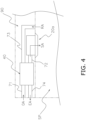
- the ventilator 40 is provided in an attic 90 of the target space SP.
- FIG. 3 is a schematic configuration diagram of the ventilator 40.
- FIG. 4 is a diagram illustrating an arrangement of the indoor unit 20a and the ventilator 40.
- the ventilator 40 mainly includes an inlet duct 71, the air supply duct 72, an outlet duct 73, an exhaust duct 74, a device body 41, and the ventilation control unit 49.
- the inlet duct 71 is connected to an inlet for taking the outdoor air OA into the target space SP.
- the air supply duct 72 is connected to the indoor unit 20a that also serves as an air supply port for supplying the outdoor air OA to the target space SP as a supply air SA.
- the outlet duct 73 is connected to an outlet for taking out the indoor air RA from the target space SP.
- the exhaust duct 74 is connected to a discharge port for discharging the indoor air RA to the outside as a discharge air EA.
- the device body 41 is connected to the inlet duct 71, the air supply duct 72, the outlet duct 73, and the exhaust duct 74.
- the device body 41 is provided with a ventilation heat exchanger 42, and two ventilation passages 43 and 44 partitioned from each other are formed so as to cross the ventilation heat exchanger 42.
- the ventilation heat exchanger 42 is a total heat exchanger that simultaneously exchanges sensible heat and latent heat between two air flows (here, the indoor air RA and the outdoor air OA), and is provided across the ventilation passages 43 and 44.
- One ventilation passage 43 has one end connected to the inlet duct 71 and the other end connected to the air supply duct 72, and constitutes an air supply path for flowing air from the outside toward the target space SP via the indoor unit 20a.
- the other ventilation path 44 has one end connected to the outlet duct 73 and the other end connected to the exhaust duct 74, and constitutes an exhaust path for flowing air from the target space SP to the outside.
- the ventilation passage 43 is provided with an air supply fan 45 driven by an air supply fan motor 45m in order to generate an air flow from the outside toward the target space SP via the indoor unit 20a, and the ventilation passage 44 is provided with an exhaust fan 46 driven by an exhaust fan motor 46m in order to generate an air flow from the target space SP toward the outside.
- the air supply fan 45 and the exhaust fan 46 are disposed downstream of the ventilation heat exchanger 42 in the air flow.
- the ventilation control unit 49 controls the operation of each unit constituting the ventilator 40.
- the ventilation control unit 49 is electrically connected to various devices of the ventilator 40, which include the air supply fan motor 45m and the exhaust fan motor 46m.
- the ventilation control unit 49 includes a control calculator and a storage device.
- the control calculator is a processor such as a CPU or a GPU.
- the storage device is a storage medium such as a RAM, a ROM, or a flash memory.
- the control calculator reads a program from the storage device and executes predetermined calculation processing in accordance with the program to control the operation of each component constituting the ventilator 40.
- the control calculator is capable of writing a result of calculation to the storage device and reading information from the storage device in accordance with the program.
- the ventilation control unit 49 also includes a timer.
- the ventilation control unit 49 exchanges control signals, measurement signals, signals related to various settings, and the like with the indoor control units 29a and 29b of the indoor units 20a and 20b, the outdoor control unit 39a of the outdoor unit 30a, and the control unit 13 of the air conditioning control apparatus 10 via the communication line 80.
- the ventilation control unit 49 the indoor control units 29a and 29b, and the outdoor control unit 39a cooperate to function as the controller C1.
- the function of the controller C1 will be described later.
- the cooperation of the indoor control units 29a and 29b of the indoor units 20a and 20b, the outdoor control unit 39a of the outdoor unit 30a, and the ventilation control unit 49 of the ventilator 40 functions as the controller C1 that controls the operation of the refrigerant system RS1.
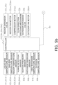
- FIGS. 5a and 5b are control block diagrams of the air conditioning system 1.
- the controller C1 is communicably connected to the liquid-side temperature sensors 61a and 61b, the gas-side temperature sensors 62a and 62b, the indoor temperature sensors 63a and 63b, the human detection sensors 64a and 64b, the suction pressure sensor 65a, the discharge pressure sensor 66a, the heat exchange temperature sensor 67a, and the outdoor temperature sensor 68a.
- the controller C1 receives measurement signals transmitted from various sensors.
- the controller C1 is electrically connected to the indoor expansion valves 23a and 23b, the indoor fan motors 22am and 22bm, the compressor motor 31am, the flow direction switching mechanism 32a, the outdoor expansion valve 34a, the outdoor fan motor 36am, the air supply fan motor 45m, and the exhaust fan motor 46m.
- the controller C1 controls the operation of the devices of the refrigerant system RS1, which include the indoor expansion valves 23a and 23b, the indoor fan motors 22am and 22bm, the compressor motor 31am, the flow direction switching mechanism 32a, the outdoor expansion valve 34a, the outdoor fan motor 36am, the air supply fan motor 45m, and the exhaust fan motor 46m, on the basis of the measurement signals of the various sensors in accordance with the control signal transmitted from the operation remote controller of the refrigerant system RS1 and the control signal transmitted from the air conditioning control apparatus 10.
- the devices of the refrigerant system RS1 which include the indoor expansion valves 23a and 23b, the indoor fan motors 22am and 22bm, the compressor motor 31am, the flow direction switching mechanism 32a, the outdoor expansion valve 34a, the outdoor fan motor 36am, the air supply fan motor 45m, and the exhaust fan motor 46m, on the basis of the measurement signals of the various sensors in accordance with the control signal transmitted from the operation remote controller of the refrigerant system RS1 and the
- the cooperation between the indoor control units 29c and 29d of the indoor units 20c and 20d and the outdoor control unit 39b of the outdoor unit 30b functions as a controller C2 that controls the operation of the refrigerant system RS2.
- the controller C2 is communicably connected to liquid-side temperature sensors 61c and 61d, gas-side temperature sensors 62c and 62d, indoor temperature sensors 63c and 63d, human detection sensors 64c and 64d, a suction pressure sensor 65b, a discharge pressure sensor 66b, a heat exchange temperature sensor 67b, and an outdoor temperature sensor 68b.
- the controller C2 receives measurement signals transmitted from various sensors.
- the controller C2 is electrically connected to indoor expansion valves 23c and 23d, indoor fan motors 22cm and 22dm, a compressor motor 31bm, a flow direction switching mechanism 32b, an outdoor expansion valve 34b, and an outdoor fan motor 36bm.
- the controller C2 controls the operation of the devices of the refrigerant system RS2, which include the indoor expansion valves 23c and 23d, the indoor fan motors 22cm and 22dm, the compressor motor 31bm, the flow direction switching mechanism 32b, the outdoor expansion valve 34b, and the outdoor fan motor 36bm, on the basis of the measurement signals of the various sensors in accordance with the control signal transmitted from the operation remote controller of the refrigerant system RS2 and the control signal transmitted from the air conditioning control apparatus 10.
- the controller C1 controls various devices of the refrigerant system RS1 to cause the indoor units 20a and 20b to perform the cooling operation, the heating operation, the fan operation, and the ventilation operation.
- the cooling operation, the heating operation, the fan operation, and the ventilation operation that the controller C1 causes the indoor unit 20a to perform will be described below.
- the controller C1 controls the flow direction switching mechanism 32a to a state indicated by the solid line in FIG. 2 to set the state of the outdoor heat exchanger 33a to the second state of functioning as a condenser. Then, the controller C1 fully opens the outdoor expansion valve 34a, and adjusts the opening degree of the indoor expansion valve 23a to set a degree of superheating of the refrigerant at a gas-side outlet of the indoor heat exchanger 21a to a predetermined target degree of superheating.
- the degree of superheating of the refrigerant at the gas-side outlet of the indoor heat exchanger 21a is calculated, for example, by subtracting an evaporation temperature converted from a measurement value (suction pressure) of the suction pressure sensor 65a from a measurement value of the gas-side temperature sensor 62a.
- the controller C1 controls an operating capacity of the compressor 31a to cause the evaporation temperature converted from the measurement value (suction pressure) of the suction pressure sensor 65a to approach a predetermined target evaporation temperature.
- the operating capacity of the compressor 31a is controlled by controlling the number of rotations of the compressor motor 31am.
- the refrigerant flows through the refrigerant circuit 50 during the cooling operation as follows.
- a low-pressure gas refrigerant in the refrigeration cycle is sucked into the compressor 31a and compressed by the compressor 31a to become a high-pressure gas refrigerant in the refrigeration cycle.
- the high-pressure gas refrigerant is sent to the outdoor heat exchanger 33a via the flow direction switching mechanism 32a, exchanges heat with heat source air supplied by the outdoor fan 36a, and is condensed into a high-pressure liquid refrigerant.
- the high-pressure liquid refrigerant flows through the liquid refrigerant pipe 54d and passes through the outdoor expansion valve 34a.
- the high-pressure liquid refrigerant sent to the indoor unit 20a is decompressed to near the suction pressure of the compressor 31a in the indoor expansion valve 23a, becomes a refrigerant in a gas-liquid two-phase state, and is sent to the indoor heat exchanger 21a.
- the refrigerant in the gas-liquid two-phase state exchanges heat with the air in the target space SP supplied to the indoor heat exchanger 21a by the indoor fan 22a in the indoor heat exchanger 21a and evaporates to become a low-pressure gas refrigerant.
- the low-pressure gas refrigerant is sent to the outdoor unit 30a via the gas refrigerant connection pipe 52, and flows into the accumulator 35a via the flow direction switching mechanism 32a.
- the low-pressure gas refrigerant flowing into the accumulator 35a is again sucked into the compressor 31a.
- the temperature of the air supplied to the indoor heat exchanger 21a decreases by heat exchange with the refrigerant flowing through the indoor heat exchanger 21a, and the air cooled by the indoor heat exchanger 21a is blown into the target space SP.
- the controller C1 controls the flow direction switching mechanism 32a to a state indicated by the broken line in FIG. 2 to set the state of the outdoor heat exchanger 33a to the first state of functioning as an evaporator. Then, the controller C1 adjusts the opening degree of the indoor expansion valve 23a to set a degree of subcooling of the refrigerant at a liquid-side outlet of the indoor heat exchanger 21a to a predetermined target degree of subcooling.
- the degree of subcooling of the refrigerant at the liquid-side outlet of the indoor heat exchanger 21a is calculated, for example, by subtracting a measurement value of the liquid-side temperature sensor 61a from a condensation temperature converted from a measurement value (discharge pressure) of the discharge pressure sensor 66a.
- the controller C1 also adjusts the opening degree of the outdoor expansion valve 34a to decompress the refrigerant flowing into the outdoor heat exchanger 33a to a pressure at which the refrigerant can evaporate in the outdoor heat exchanger 33a.
- the controller C1 controls an operating capacity of the compressor 31a to cause the condensation temperature converted from the measurement value (discharge pressure) of the discharge pressure sensor 66a to approach a predetermined target condensation temperature.
- the operating capacity of the compressor 31a is controlled by controlling the number of rotations of the compressor motor 31am.
- the refrigerant flows through the refrigerant circuit 50 during the heating operation as follows.
- a low-pressure gas refrigerant in the refrigeration cycle is sucked into the compressor 31a and compressed by the compressor 31a to become a high-pressure gas refrigerant in the refrigeration cycle.
- the high-pressure gas refrigerant is sent to the indoor heat exchanger 21a via the flow direction switching mechanism 32a, exchanges heat with the air in the target space SP supplied by the indoor fan 22a, and is condensed into a high-pressure liquid refrigerant.
- the temperature of the air supplied to the indoor heat exchanger 21a rises by heat exchange with the refrigerant flowing through the indoor heat exchanger 21a, and the air heated by the indoor heat exchanger 21a is blown into the target space SP.
- the high-pressure liquid refrigerant having passed through the indoor heat exchanger 21a passes through the indoor expansion valve 23a to be decompressed.
- the refrigerant decompressed in the indoor expansion valve 23a is sent to the outdoor unit 30a via the liquid refrigerant connection pipe 51, and flows into the liquid refrigerant pipe 54d.
- the refrigerant flowing through the liquid refrigerant pipe 54d is decompressed to near the suction pressure of the compressor 31a when passing through the outdoor expansion valve 34a, becomes the refrigerant in the gas-liquid two-phase state, and flows into the outdoor heat exchanger 33a.
- the low-pressure refrigerant in the gas-liquid two-phase state that has flowed into the outdoor heat exchanger 33a exchanges heat with the heat source air supplied by the outdoor fan 36a, evaporates to become a low-pressure gas refrigerant, and flows into the accumulator 35a via the flow direction switching mechanism 32a.
- the low-pressure gas refrigerant flowing into the accumulator 35a is again sucked into the compressor 31a.
- the controller C1 When receiving an instruction to cause the indoor unit 20a to perform the fan operation from the operation remote controller or the air conditioning control apparatus 10, the controller C1 fully closes the indoor expansion valve 23a. Then, the controller C1 controls the indoor fan motor 22am so as to have a predetermined target air volume, sucks the indoor air RA of the target space SP into the indoor unit 20a, and supplies the sucked indoor air RA to the target space SP again. As a result, the indoor air RA in the target space SP is stirred or circulated.
- the controller C1 When receiving an instruction to cause the indoor unit 20a to perform the ventilation operation from the operation remote controller or the air conditioning control apparatus 10, the controller C1 causes the indoor unit 20 a to perform the fan operation with a low air volume and activates the air supply fan 45 and the exhaust fan 46 of the ventilator 40. Then, the outdoor air OA flowing into the device body 41 from the outside through the inlet duct 71 and the indoor air RA flowing into the device body 41 from the target space SP through the outlet duct 73 exchange heat in the ventilation heat exchanger 42. Next, the outdoor air OA having exchanged heat in the ventilation heat exchanger 42 is supplied as the supply air SA from the device body 41 to the target space SP via the indoor unit 20a through the air supply duct 72. The indoor air RA having exchanged heat in the ventilation heat exchanger 42 is discharged as the discharge air EA from the device body 41 to the outside through the exhaust duct 74.
- the air conditioning control apparatus 10 controls the indoor units 20a to 20d, the outdoor units 30a and 30b, and the ventilator 40 to execute various operations and various functions. As shown in FIG. 5a , the air conditioning control apparatus 10 mainly includes a storage unit 11, an input-output unit 12, and the control unit 13.
- the storage unit 11 is a storage device such as a RAM, a ROM, or a hard disk drive (HDD).
- the storage unit 11 stores a program executed by the control unit 13, data necessary for executing the program, and the like.
- the input-output unit 12 is a touch panel display for inputting and outputting information to and from the air conditioning control apparatus 10.
- a user can input various types of information and execute various operations and various functions by tapping, sliding, and the like on the display with a finger, for example.
- the input-output unit 12 can display operation statuses and the like of the indoor units 20a to 20d, the outdoor units 30a and 30b, and the ventilator 40.
- the control unit 13 is a calculation processor such as a CPU. As shown in FIG. 5a , the control unit 13 reads and executes a program stored in the storage unit 11 to implement various functions of the air conditioning control apparatus 10. The control unit 13 can also write a calculation result to the storage unit 11 and read information stored in the storage unit 11 in accordance with the program.
- the control unit 13 exchanges control signals, measurement signals, signals related to various settings, and the like with the indoor control units 29a to 29d of the indoor units 20a to 20d, the outdoor control units 39a and 39b of the outdoor units 30a and 30b, and the ventilation control unit 49 of the ventilator 40 via the communication line 80. Then, the control unit 13 controls the indoor units 20a to 20d, the outdoor units 30a and 30b, and the ventilator 40 in cooperation with the controllers C1 and C2. In particular, the control unit 13 can cause the indoor units 20a to 20d to perform the cooling operation, the heating operation, the fan operation, or the ventilation operation.
- control unit 13 has a grouping function and a thermal load adjustment function as main functions.
- a group setting function is a function of setting a group GP of the indoor units to be subjected to the thermal load adjustment function.
- the control unit 13 sets the indoor unit designated by using the input-output unit 12 among the indoor units 20a to 20d as one group GP (indoor unit group). For example, the control unit 13 may set all the indoor units 20a to 20d as one group GP. The control unit 13 may also set, for example, some of the indoor units 20a to 20d such as the indoor unit 20a and the indoor unit 20b as one group GP. The control unit 13 may also set, as one group GP, indoor units belonging to different refrigerant systems, such as the indoor unit 20a and the indoor unit 20c, for example. As shown in FIG. 1 , the present embodiment will be described on the assumption that the indoor units 20a to 20c are set as one group GP1.
- the thermal load adjustment function is a function of eliminating a difference between thermal loads when a difference of a certain level or more occurs in thermal loads to be processed by each of the indoor units 20a to 20c belonging to the group GP1.
- the indoor units 20a to 20c are performing the cooling operation or the heating operation.
- step S1 the control unit 13 starts the thermal load adjustment function by an instruction from the input-output unit 12 or the like.
- step S1 ends and the processing proceeds to step S2, the control unit 13 stands by for a predetermined time T1.
- step S2 ends and the processing proceeds to step S3, the control unit 13 determines whether a difference of a certain level or more occurs in thermal loads to be processed by each of the indoor units 20a to 20c.
- the thermal load to be processed by each of the indoor units 20a to 20c is determined on the basis of a temperature difference ⁇ T between a set temperature and a room temperature of each of the indoor units 20a to 20c. Specifically, it is regarded that the larger the temperature difference ⁇ T, the larger the thermal load.
- the room temperature can be acquired from measurement values of the indoor temperature sensors 63a to 63c of the indoor units 20a to 20c.
- step S3 the control unit 13 determines whether there is a difference of a certain level or more between a maximum value and a minimum value of the temperature differences ⁇ T of the indoor units 20a to 20c.
- the "difference of a certain level or more" is, for example, 5°C.
- step S3 when there is a difference of a certain level or more between the maximum value and the minimum value of the temperature differences ⁇ T, the processing proceeds to step S4.
- step S3 when there is not a difference of a certain level or more between the maximum value and the minimum value of the temperature differences ⁇ T, the processing returns to step S2, and the control unit 13 stands by for the predetermined time T1 again. In other words, the control unit 13 determines whether there is a difference of a certain level or more between the maximum value and the minimum value of the temperature differences ⁇ T of the indoor units 20a to 20c every predetermined time T1.
- step S3 ends and the processing proceeds to step S4, the control unit 13 divides the indoor units 20a to 20c into a first indoor unit and a second indoor unit.
- the control unit 13 divides the indoor units 20a to 20c into the first indoor unit and the second indoor unit so that the second indoor unit has a smaller thermal load to be processed than the first indoor unit.
- the control unit 13 sets the indoor unit having the largest thermal load to be processed as the first indoor unit, and sets the other indoor units as the second indoor units. Therefore, in step S4, the control unit 13 sets the indoor unit having the largest temperature difference ⁇ T among the indoor units 20a to 20c as the first indoor unit, and sets the other indoor units as the second indoor units.
- the indoor unit 20c is the first indoor unit
- the indoor units 20a and 20b are the second indoor units.
- step S4 ends and the processing proceeds to step S5, the control unit 13 causes the first indoor unit to perform the cooling operation or the heating operation. Since the first indoor unit has a relatively large thermal load to be processed, the control unit 13 causes the first indoor unit to perform the cooling operation or the heating operation to actively process the thermal load. In the present embodiment, the control unit 13 causes the first indoor unit currently performing the cooling operation to continuously perform the cooling operation. The control unit 13 causes the first indoor unit currently performing the heating operation to continuously perform the heating operation. In the above example, the control unit 13 causes the indoor unit 20c to continuously perform the cooling operation or the heating operation.
- step S5 the control unit 13 causes the second indoor unit to perform the fan operation or the ventilation operation. Since the second indoor unit has a relatively small thermal load to be processed, the control unit 13 causes the second indoor unit to perform the fan operation or the ventilation operation, and stirs or circulates the indoor air RA in the target space SP to assist thermal load processing performed by the first indoor unit. In the present embodiment, when the second indoor unit cannot perform the ventilation operation, the control unit 13 causes the second indoor unit to perform the fan operation. When the second indoor unit can perform the ventilation operation, the control unit 13 causes the second indoor unit to perform the ventilation operation if the set temperature of the second indoor unit and the outdoor temperature are within a predetermined range, and causes the second indoor unit to perform the fan operation otherwise.
- the outdoor temperature can be acquired from a measurement value of the outdoor temperature sensor 68a.
- the control unit 13 since the indoor unit 20a can perform the ventilation operation, the control unit 13 causes the indoor unit 20a to perform the ventilation operation if the set temperature of the indoor unit 20a and the outdoor temperature are within the predetermined range, and causes the indoor unit 20a to perform the fan operation otherwise. Since the indoor unit 20b cannot perform the ventilation operation, the control unit 13 causes the indoor unit 20b to perform the fan operation. At this time, in order to further stir or circulate the indoor air RA in the target space SP, the control unit 13 may cause the second indoor unit to perform the fan operation or the ventilation operation with an air volume higher than an air volume during an operation before the fan operation or the ventilation operation is performed.
- step S5 ends and the processing proceeds to step S6, the control unit 13 stands by for a predetermined time T2.
- step S6 ends and the processing proceeds to step S7, the control unit 13 determines whether there is a difference of a certain level or more between the maximum value and the minimum value of the temperature differences ⁇ T of the indoor units 20a to 20c.
- the processing returns to step S6, and the control unit 13 stands by for the predetermined time T2 again.
- the control unit 13 determines whether there is a difference of a certain level or more between the maximum value and the minimum value of the temperature differences ⁇ T of the indoor units 20a to 20c every predetermined time T2.
- the processing proceeds to step S8.
- step S7 ends and the processing proceeds to step S8, the control unit 13 switches the fan operation or the ventilation operation performed by the second indoor unit to the operation before the fan operation or the ventilation operation is performed.
- the control unit 13 switches the fan operation or the ventilation operation performed by the indoor units 20a and 20b to the operation before the fan operation or the ventilation operation is performed.
- step S8 ends and the processing proceeds to step S2, the control unit 13 determines whether there is a difference of a certain level or more between the maximum value and the minimum value of the temperature differences ⁇ T of the indoor units 20a to 20c every predetermined time T1 again.
- the control unit 13 repeats this processing until the thermal load adjustment function is stopped by an instruction from the input-output unit 12 or the like.
- the control unit 13 for example, switches the fan operation or the ventilation operation performed by the second indoor unit to the operation before the fan operation or the ventilation operation is performed.
- the air conditioning control apparatus 10 controls the plurality of indoor units 20a to 20d.
- the air conditioning control apparatus 10 sets the indoor units 20a to 20c having been designated among the plurality of indoor units 20a to 20d as one group GP1.
- the air conditioning control apparatus 10 causes the first indoor unit belonging to the group GP1 to perform the cooling operation or the heating operation and causes the second indoor unit belonging to the group GP1 to perform the fan operation or the ventilation operation when a difference of a certain level or more occurs in thermal loads to be processed by each of the indoor units 20a to 20c belonging to the group GP1.
- the air conditioning control apparatus 10 causes the second indoor unit to perform the fan operation or the ventilation operation when a difference of a certain level or more occurs in thermal loads to be processed by each of the indoor units 20a to 20c belonging to the group GP1. As a result, the air conditioning control apparatus 10 can improve the non-uniform temperature distribution in the target space SP by stirring the indoor air RA in the target space SP.
- the air conditioning control apparatus 10 causes the first indoor unit to perform the cooling operation or the heating operation and causes the second indoor unit to perform the fan operation or the ventilation operation on the basis of the temperature difference ⁇ T between the set temperature and the room temperature of each of the indoor units 20a to 20c belonging to the group GP1.
- the air conditioning control apparatus 10 can easily know the thermal load to be processed by each of the indoor units 20a to 20c, and can cause the second indoor unit to perform the fan operation or the ventilation operation.
- the thermal load to be processed by the second indoor unit is smaller than the thermal load to be processed by the first indoor unit.
- the air conditioning control apparatus 10 stirs the indoor air RA in the target space SP by using the indoor unit with a smaller thermal load to be processed while continuing the operation of the indoor unit with a larger thermal load, and thus, can improve the non-uniform temperature distribution in the target space SP.
- the air conditioning control apparatus 10 causes the second indoor unit to perform the fan operation or the ventilation operation with the air volume higher than the air volume during an operation before the fan operation or the ventilation operation is performed.
- the air conditioning control apparatus 10 can further improve the non-uniform temperature distribution in the target space SP by further stirring the indoor air RAin the target space SP.
- the air conditioning control apparatus 10 switches the fan operation or the ventilation operation performed by the second indoor unit to the operation before the fan operation or the ventilation operation is performed, on the basis of the temperature difference ⁇ T between the set temperature and the room temperature of the second indoor unit or the thermal load to be processed by each of the indoor units 20a to 20c other than the second indoor unit and belonging to the group GP1.
- the air conditioning control apparatus 10 can cause the second indoor unit to return to the operation before the fan operation or the ventilation operation is performed.
- the air conditioning system 1 includes the air conditioning control apparatus 10 and the plurality of indoor units 20a to 20d.
- the air conditioning system 1 includes four indoor units 20a to 20d, two outdoor units 30a and 30b, and one ventilator 40.
- the air conditioning system 1 has two refrigerant systems RS 1 and RS2.
- the configuration of the air conditioning system 1 is arbitrary, and for example, the air conditioning system 1 may include more devices and more refrigerant systems.
- the indoor unit 20a is in conjunction with the ventilator 40 in order to cause the indoor unit 20a to perform the ventilation operation.
- the ventilator 40 may be in conjunction with any of the indoor units 20a to 20d.
- the thermal load to be processed by each of the indoor units 20a to 20c belonging to the group GP1 is determined on the basis of the temperature difference ⁇ T between the set temperature and the room temperature of each of the indoor units 20a to 20c.
- the air conditioning control apparatus 10 may determine the thermal load to be processed by each of the indoor units 20a to 20c on the basis of a target condensation temperature (in the case of the heating operation) or a target evaporation temperature (in the case of the cooling operation) requested by each of the indoor units 20a to 20c to each of the outdoor units 30a and 30b to which the indoor units 20a to 20c are respectively connected.
- a target condensation temperature in the case of the heating operation
- a target evaporation temperature in the case of the cooling operation
- the air conditioning control apparatus 10 causes the first indoor unit to perform the cooling operation or the heating operation and causes the second indoor unit to perform the fan operation or the ventilation operation on the basis of the target condensation temperature (in the case of the heating operation) or the target evaporation temperature (in the case of the cooling operation) requested by each of the indoor units 20a to 20c to each of the outdoor units 30a and 30b to which the indoor units 20a to 20c are respectively connected.
- the indoor units 20a to 20c belonging to the group GP1 form a refrigeration cycle together with the outdoor units 30a and 30b.
- the air conditioning control apparatus 10 determines the thermal load to be processed by each of the indoor units 20a to 20c on the basis of a temperature difference between the evaporation temperature converted from the current measurement values (suction pressures) of the suction pressure sensors 65a and 65b and the target evaporation temperature. In this case, it is considered that the larger the temperature difference, the larger the thermal load.
- the air conditioning control apparatus 10 can more accurately know the thermal load to be processed by each of the indoor units 20a to 20c, and can cause the second indoor unit to perform the fan operation or the ventilation operation.
- the air conditioning control apparatus 10 determines whether there is a difference of a certain level or more between the maximum value and the minimum value of the temperature differences ⁇ T of the indoor units 20a to 20c belonging to the group GP1.
- the air conditioning control apparatus 10 may determine whether there is a variance of a certain level or more between the temperature differences ⁇ T of the indoor units 20a to 20c.
- the air conditioning control apparatus 10 sets the indoor unit having the largest thermal load to be processed as the first indoor unit, and sets the other indoor units as the second indoor units.
- the air conditioning control apparatus 10 may set a predetermined number of indoor units as the first indoor unit and set the other indoor units as the second indoor unit, for example, in the order of a larger thermal load to be processed.
- the air conditioning control apparatus 10 may have a function (automatic stop function) of automatically stopping the cooling operation or the heating operation of the indoor units 20a to 20d in accordance with the set temperature. Specifically, while the indoor units 20a to 20d are performing the cooling operation, the air conditioning control apparatus 10 automatically stops the cooling operation of the indoor units 20a to 20d when the room temperature falls below the set temperature and the temperature difference between the set temperature and the room temperature becomes larger than a predetermined threshold value (when an automatic stop condition is satisfied).
- a function automatic stop function
- the air conditioning control apparatus 10 automatically stops the heating operation of the indoor units 20a to 20d when the room temperature exceeds the set temperature and the temperature difference between the set temperature and the room temperature becomes larger than a predetermined threshold value (when an automatic stop condition is satisfied).
- the predetermined threshold value is, for example, 2°C.
- the indoor unit satisfying the automatic stop condition is an indoor unit having a small thermal load to be processed.
- the air conditioning control apparatus 10 may use the automatic stop function to set the indoor unit that satisfies the automatic stop condition as the second indoor unit. In this case, the air conditioning control apparatus 10 does not stop the operation of the indoor unit that satisfies the automatic stop condition, but causes the indoor unit that satisfies the automatic stop condition to perform the fan operation or the ventilation operation.
- the air conditioning control apparatus 10 can cause the second indoor unit to perform the fan operation or the ventilation operation by using the automatic stop function.
- the air conditioning control apparatus 10 may perform learning for determining the first indoor unit and the second indoor unit so as to reduce a total power consumption of the group GP1.
- the total power consumption of the group GP1 is, for example, a sum of power consumption of the indoor units 20a to 20c belonging to the group GP1.
- the air conditioning control apparatus 10 uses, as the power consumption of the indoor units 20a and 20b, power consumption of the compressor 31a of the outdoor unit 30a distributed by the opening degrees of the indoor expansion valves 23a and 23b.
- the air conditioning control apparatus 10 may determine the first indoor unit and the second indoor unit while performing deep reinforcement learning with the total power consumption of the group GP1 being reduced as a reward.
- the air conditioning control apparatus 10 can improve the non-uniform temperature distribution in the target space SP and reduce the total power consumption of the group GP1.
- the air conditioning control apparatus 10 may learn a start time of the cooling operation or the heating operation of the indoor units 20a to 20c belonging to the group GP1, and may automatically start the cooling operation or the heating operation before the predicted start time.
- a recursive neural network, a state space model, or the like is used for the learning.
- the air conditioning control apparatus 10 can cause the thermal load to be processed in advance by automatically starting the cooling operation or the heating operation before the predicted start time.
- the air conditioning control apparatus 10 may include a human detector as a functional block.
- the human detector detects a person in the target space SP by using human detection sensors 64a to 64d.
- the air conditioning control apparatus 10 causes at least one indoor unit belonging to the group GP1 to perform the fan operation or the ventilation operation to circulate the indoor air RA in the target space SP.
- the air conditioning control apparatus 10 can improve the non-uniform temperature distribution in the target space SP by circulating the indoor air RA in the target space SP while there is no person in the target space SP.
- the air conditioning control apparatus 10 may have a function of equalizing the set temperatures of the indoor units 20a to 20c belonging to the group GP1 if a predetermined condition is satisfied. For example, when the difference between a maximum value and a minimum value of measured values of the indoor temperature sensors 63a to 63c is larger than a predetermined value, the air conditioning control apparatus 10 sets the set temperatures of the indoor units 20a to 20c to an average value of the set temperatures.
- the predetermined value is, for example, 2°C.
- the air conditioning control apparatus 10 can further improve the non-uniform temperature distribution in the target space SP by using both the function of equalizing the set temperatures of the indoor units 20a to 20c belonging to the group GP1 and the thermal load adjustment function.
- Patent Literature 1 JP H05-312378 A
Landscapes
- Engineering & Computer Science (AREA)
- Chemical & Material Sciences (AREA)
- Combustion & Propulsion (AREA)
- Mechanical Engineering (AREA)
- General Engineering & Computer Science (AREA)
- Signal Processing (AREA)
- Physics & Mathematics (AREA)
- Fuzzy Systems (AREA)
- Mathematical Physics (AREA)
- Air Conditioning Control Device (AREA)
Abstract
Description
- The present invention relates to an air conditioning control apparatus and an air conditioning system.
- As disclosed in Patent Literature 1 (
JP H05-312378 A - As in
Patent Literature 1, there is a problem that the non-uniform temperature distribution in the space cannot be sufficiently improved by simply adjusting the circulation amount of the refrigerant because warm air is accumulated on an upper side and cold air is accumulated on a lower side. - An air conditioning control apparatus according to a first aspect controls a plurality of indoor units. The air conditioning control apparatus sets the indoor units having been designated among the plurality of indoor units as an indoor unit group. The air conditioning control apparatus causes a first indoor unit belonging to the indoor unit group to perform a cooling operation or a heating operation and causes a second indoor unit belonging to the indoor unit group to perform a fan operation or a ventilation operation when a difference of a certain level or more occurs in thermal loads to be processed by each of the indoor units belonging to the indoor unit group.
- The air conditioning control apparatus according to the first aspect causes the second indoor unit to perform the fan operation or the ventilation operation when a difference of a certain level or more occurs in thermal loads to be processed by each of the indoor units belonging to the indoor unit group. As a result, the air conditioning control apparatus can improve a non-uniform temperature distribution in a space by stirring air in the space.
- An air conditioning control apparatus according to a second aspect is the air conditioning control apparatus according to the first aspect, causes the first indoor unit to perform the cooling operation or the heating operation and causes the second indoor unit to perform the fan operation or the ventilation operation on the basis of a temperature difference between a set temperature and a room temperature of each of the indoor units belonging to the indoor unit group.
- On the basis of the temperature difference between the set temperature and the room temperature of each of the indoor units, the air conditioning control apparatus according to the second aspect can easily know the thermal load to be processed by each of the indoor units, and can cause the second indoor unit to perform the fan operation or the ventilation operation.
- An air conditioning control apparatus according to a third aspect is the air conditioning control apparatus according to the first or second aspect, in which the thermal load to be processed by the second indoor unit is smaller than the thermal load to be processed by the first indoor unit.
- With such a configuration, the air conditioning control apparatus according to the third aspect stirs the air in the space by using the indoor unit with a smaller thermal load to be processed while continuing the operation of the indoor unit with a larger thermal load, and thus, can improve the non-uniform temperature distribution in the space.
- An air conditioning control apparatus according to a fourth aspect is the air conditioning control apparatus according to any of the first to third aspects, and has a function of automatically stopping the cooling operation or the heating operation of the indoor unit in accordance with the set temperature. The air conditioning control apparatus sets the indoor unit to be automatically stopped as the second indoor unit.
- With such a configuration, the air conditioning control apparatus according to the fourth aspect can cause the second indoor unit to perform the fan operation or the ventilation operation by using the function of automatically stopping the cooling operation or the heating operation.
- An air conditioning control apparatus according to a fifth aspect is the air conditioning control apparatus according to any of the first to fourth aspects, in which each of the indoor units belonging to the indoor unit group forms a refrigeration cycle together with an outdoor unit. The air conditioning control apparatus causes the first indoor unit to perform the cooling operation or the heating operation and causes the second indoor unit to perform the fan operation or the ventilation operation on the basis of a condensation temperature or an evaporation temperature requested by each of the indoor units to each of the outdoor units to which the indoor units are respectively connected.
- On the basis of the condensation temperature or the evaporation temperature required by each of the indoor units to each of the outdoor units, the air conditioning control apparatus according to the fifth aspect can more accurately know the thermal load to be processed by the each of the indoor units, and can cause the second indoor unit to perform the fan operation or the ventilation operation.
- An air conditioning control apparatus according to a sixth aspect is the air conditioning control apparatus according to any of the first to fifth aspects, and causes the second indoor unit to perform the fan operation or the ventilation operation with an air volume higher than an air volume during an operation before the fan operation or the ventilation operation is performed.
- With such a configuration, the air conditioning control apparatus according to the sixth aspect can further improve the non-uniform temperature distribution in the space by further stirring the air in the space.
- An air conditioning control apparatus according to a seventh aspect is the air conditioning control apparatus according to any of the first to sixth aspects, and switches the fan operation or the ventilation operation performed by the second indoor unit to the operation before the fan operation or the ventilation operation is performed, on the basis of the temperature difference between the set temperature and the room temperature of the second indoor unit or the thermal load to be processed by each of the indoor units other than the second indoor unit and belonging to the indoor unit group.
- With such a configuration, after the non-uniform temperature distribution in the space is improved, the air conditioning control apparatus according to the seventh aspect can cause the second indoor unit to return to an operation before the fan operation or the ventilation operation is performed.
- An air conditioning control apparatus according to an eighth aspect is the air conditioning control apparatus according to any of the first to seventh aspects, and performs learning for determining the first indoor unit and the second indoor unit so as to reduce a total power consumption of the indoor unit group.
- With such a configuration, the air conditioning control apparatus according to the eighth aspect can improve the non-uniform temperature distribution in the space and reduce the total power consumption of the indoor unit group.
- An air conditioning control apparatus according to a ninth aspect is the air conditioning control apparatus according to any of the first to eighth aspects, learns a start time of the cooling operation or the heating operation of the indoor units belonging to the indoor unit group, and automatically starts the cooling operation or the heating operation before the predicted start time.
- The air conditioning control apparatus according to the ninth aspect can cause the thermal load to be processed in advance by automatically starting the cooling operation or the heating operation before the predicted start time.
- An air conditioning control apparatus according to a tenth aspect is the air conditioning control apparatus according to any of the first to ninth aspects, and further includes a human detector. The human detector detects a person in the space. When there is no person in the space, the air conditioning control apparatus causes at least one indoor unit belonging to the indoor unit group to circulate the air in the space.
- With such a configuration, the air conditioning control apparatus according to the tenth aspect can improve the non-uniform temperature distribution in the space by circulating the air in the space when there is no person in the space.
- An air conditioning system according to an eleventh aspect includes the air conditioning control apparatus according to any one of the first to tenth aspects and the plurality of indoor units.
-
-
FIG. 1 is a schematic configuration diagram of an air conditioning system. -
FIG. 2 is a diagram showing a refrigerant circuit of a refrigerant system. -
FIG. 3 is a schematic configuration diagram of a ventilator. -
FIG. 4 is a diagram illustrating an arrangement of an indoor unit and the ventilator. -
FIG. 5a is a control block diagram of the air conditioning system. -
FIG. 5b is a control block diagram of the air conditioning system. -
FIG. 6 is a flowchart for describing processing of a thermal load adjustment function. - An
air conditioning system 1 constitutes a vapor compression refrigeration cycle and performs air conditioning of a target space SP (space). In the present embodiment, theair conditioning system 1 is a so-called multi-air conditioning system for buildings.FIG. 1 is a schematic configuration diagram of theair conditioning system 1. As shown inFIG. 1 , theair conditioning system 1 mainly includes an airconditioning control apparatus 10 and a plurality ofindoor units 20a to 20d. Theair conditioning system 1 includesoutdoor units ventilator 40. Theindoor units 20a to 20d, theoutdoor units ventilator 40 are installed in the target space SP. - The
outdoor units conditioning control apparatus 10 are communicably connected by acommunication line 80. Theoutdoor unit 30a is communicably connected to theindoor units ventilator 40 via thecommunication line 80. Theoutdoor unit 30b is communicably connected to theindoor units 20c and 20d via thecommunication line 80. - The
outdoor unit 30a and theindoor units outdoor unit 30b and theindoor units 20c and 20d constitute a refrigerant system RS2.FIG. 2 is a diagram showing the refrigerant system RS1 of arefrigerant circuit 50. As shown inFIG. 2 , theoutdoor unit 30a and theindoor units refrigerant connection pipe 51 and a gasrefrigerant connection pipe 52 to constitute therefrigerant circuit 50. - In the present embodiment, the
indoor units 20a to 20d perform a cooling operation, a heating operation, a fan operation, or a ventilation operation. The cooling operation is an operation of cooling air in the target space SP. The heating operation is an operation of heating air in the target space SP. The fan operation is an operation of stirring or circulating the air in the target space SP. The ventilation operation is an operation of taking out indoor air RA from the target space SP and taking outdoor air OA into the target space SP by using theventilator 40. In the present embodiment, theindoor unit 20a is connected to theventilator 40 by anair supply duct 72. Theindoor unit 20a can perform the ventilation operation in conjunction with theventilator 40. - Hereinafter, the air
conditioning control apparatus 10, theindoor units outdoor unit 30a, and theventilator 40 included in theair conditioning system 1 will be described in detail. The description of theindoor units 20c and 20d and theoutdoor unit 30b is basically similar to the description of theindoor units outdoor unit 30a except for the presence or absence of theventilator 40, and thus, will be omitted unless otherwise necessary. - The
indoor units indoor units FIG. 2 , theindoor units indoor heat exchangers indoor fans 22a and 22b,indoor expansion valves indoor control units side temperature sensors side temperature sensors indoor temperature sensors human detection sensors FIG. 2 , theindoor units refrigerant pipes indoor heat exchangers refrigerant connection pipe 51, andgas refrigerant pipes indoor heat exchangers refrigerant connection pipe 52. - The
indoor heat exchangers indoor heat exchangers indoor heat exchangers indoor heat exchangers - The
indoor heat exchangers indoor heat exchangers - The
indoor fans 22a and 22b suck the indoor air RA into theindoor units indoor heat exchangers indoor heat exchangers indoor fans 22a and 22b are, for example, centrifugal fans such as turbo fans or sirocco fans. Theindoor fans 22a and 22b are driven by indoor fan motors 22am and 22bm. The indoor fan motors 22am and 22bm have the number of rotations controllable by an inverter. - The
indoor expansion valves refrigerant pipes indoor expansion valves refrigerant pipes indoor expansion valves - The liquid-
side temperature sensors refrigerant pipes side temperature sensors refrigerant pipes - The gas-
side temperature sensors gas refrigerant pipes side temperature sensors gas refrigerant pipes - The
indoor temperature sensors indoor temperature sensors indoor units - The liquid-
side temperature sensors side temperature sensors indoor temperature sensors - The
human detection sensors human detection sensors indoor units human detection sensors - The
indoor control units indoor units - The
indoor control units indoor units indoor expansion valves indoor control units indoor units side temperature sensors side temperature sensors indoor temperature sensors human detection sensors - The
indoor control units indoor units indoor control units - The
indoor control units indoor control units outdoor control unit 39a of theoutdoor unit 30a, theventilation control unit 49 of theventilator 40, and thecontrol unit 13 of the airconditioning control apparatus 10 via thecommunication line 80. - The
indoor control units outdoor control unit 39a, and theventilation control unit 49 cooperate to function as a controller C1. The function of the controller C1 will be described later. - The
outdoor unit 30a is a unit installed on a rooftop or the like of a building in which the refrigerant system RS1 is installed. As shown inFIG. 2 , theoutdoor unit 30a mainly includes acompressor 31a, a flowdirection switching mechanism 32a, anoutdoor heat exchanger 33a, anoutdoor expansion valve 34a, anaccumulator 35a, anoutdoor fan 36a, a liquid-side shutoff valve 37a, a gas-side shutoff valve 38a, anoutdoor control unit 39a, asuction pressure sensor 65a, adischarge pressure sensor 66a, a heatexchange temperature sensor 67a, and anoutdoor temperature sensor 68a. Theoutdoor unit 30a also includes asuction pipe 54a, adischarge pipe 54b, a firstgas refrigerant pipe 54c, a liquidrefrigerant pipe 54d, and a secondgas refrigerant pipe 54e. - The
suction pipe 54a connects the flowdirection switching mechanism 32a and a suction side of thecompressor 31a. Thesuction pipe 54a is provided with theaccumulator 35a. Thedischarge pipe 54b connects a discharge side of thecompressor 31a and the flowdirection switching mechanism 32a. The firstgas refrigerant pipe 54c connects the flowdirection switching mechanism 32a and a gas-side end of theoutdoor heat exchanger 33a. The liquidrefrigerant pipe 54d connects a liquid side of theoutdoor heat exchanger 33a and the liquidrefrigerant connection pipe 51. The liquidrefrigerant pipe 54d is provided with theoutdoor expansion valve 34a. The liquid-side shutoff valve 37a is provided at a connection portion between the liquidrefrigerant pipe 54d and the liquidrefrigerant connection pipe 51. The secondgas refrigerant pipe 54e connects the flowdirection switching mechanism 32a and the gasrefrigerant connection pipe 52. The gas-side shutoff valve 38a is provided at a connection portion between the secondgas refrigerant pipe 54e and the gasrefrigerant connection pipe 52. - As shown in
FIG. 2 , thecompressor 31a is a device that sucks a low-pressure refrigerant in a refrigeration cycle from thesuction pipe 54a, compresses the refrigerant by a compression mechanism (not shown), and discharges the compressed refrigerant to thedischarge pipe 54b. - The type of the
compressor 31a may be of any type. For example, thecompressor 31a is a rotary type or scroll type capacity compressor. Thecompressor 31a includes a compression mechanism (not shown) driven by a compressor motor 31am. The compressor motor 31am has the number of rotations controllable by an inverter. - The flow
direction switching mechanism 32a is a mechanism that changes a state of theoutdoor heat exchanger 33a between a first state of functioning as an evaporator and a second state of functioning as a condenser by switching a flow direction of the refrigerant. When the flowdirection switching mechanism 32a sets the state of theoutdoor heat exchanger 33a to the first state, theindoor heat exchangers direction switching mechanism 32a sets the state of theoutdoor heat exchanger 33a to the second state, theindoor heat exchangers - As shown in
FIG. 2 , the flowdirection switching mechanism 32a is configured to switch the flow direction of the refrigerant discharged from thecompressor 31a between a first flow direction A and a second flow direction B. When the flowdirection switching mechanism 32a switches the flow direction of the refrigerant to the first flow direction A, the state of theoutdoor heat exchanger 33a becomes the first state. When the flowdirection switching mechanism 32a switches the flow direction of the refrigerant to the second flow direction B, the state of theoutdoor heat exchanger 33a becomes the second state. - In the present embodiment, the flow
direction switching mechanism 32a is a four-way switching valve. - During the heating operation, the flow direction of the refrigerant discharged from the
compressor 31a is switched to the first flow direction A by the flowdirection switching mechanism 32a. When the flow direction of the refrigerant is set to the first flow direction A, the flowdirection switching mechanism 32a causes thesuction pipe 54a to communicate with the firstgas refrigerant pipe 54c and causes thedischarge pipe 54b to communicate with the secondgas refrigerant pipe 54e as indicated by a broken line in the flowdirection switching mechanism 32a inFIG. 2 . When the refrigerant flows in the first flow direction A, the refrigerant discharged from thecompressor 31a flows through therefrigerant circuit 50 in the order of theindoor heat exchangers indoor expansion valves outdoor expansion valve 34a, and theoutdoor heat exchanger 33a, and returns to thecompressor 31a. - During the cooling operation, the flow direction of the refrigerant discharged from the
compressor 31a is switched to the second flow direction B by the flowdirection switching mechanism 32a. When the flow direction of the refrigerant is set to the second flow direction B, the flowdirection switching mechanism 32a causes thesuction pipe 54a to communicate with the secondgas refrigerant pipe 54e and causes thedischarge pipe 54b to communicate with the firstgas refrigerant pipe 54c as indicated by a solid line in the flowdirection switching mechanism 32a inFIG. 2 . When the refrigerant flows in the second flow direction B, the refrigerant discharged from thecompressor 31a flows through therefrigerant circuit 50 in the order of theoutdoor heat exchanger 33a, theoutdoor expansion valve 34a, theindoor expansion valves indoor heat exchangers compressor 31a. - In the
outdoor heat exchanger 33a, heat is exchanged between the refrigerant flowing through theoutdoor heat exchanger 33a and the outdoor air OA. Theoutdoor heat exchanger 33a may have any structure. For example, theoutdoor heat exchanger 33a is a cross-fin type fin-and-tube heat exchanger including a heat transfer tube (not shown) and a plurality of fines (not shown). - The
outdoor heat exchanger 33a functions as an evaporator during the heating operation and as a condenser during the cooling operation. - The
outdoor expansion valve 34a is mechanisms for adjusting pressure and flow rate of the refrigerant flowing through the liquidrefrigerant pipe 54d. As shown inFIG. 2 , theoutdoor expansion valve 34a is provided in the liquidrefrigerant pipe 54d. In the present embodiment, theoutdoor expansion valve 34a is an electronic expansion valve whose opening degree is adjustable. - The
accumulator 35a has a gas liquid separating function of separating refrigerant flowing into theaccumulator 35a into a gas refrigerant and a liquid refrigerant. As shown inFIG. 2 , theaccumulator 35a is provided in thesuction pipe 54a. The refrigerant flowing into theaccumulator 35a is separated into a gas refrigerant and a liquid refrigerant, and the gas refrigerant collecting in an upper space flows into thecompressor 31a. - The
outdoor fan 36a is a fan that sucks outdoor air OA into theoutdoor unit 30a, supplies the outdoor air OA to theoutdoor heat exchanger 33a, and discharges the outdoor air OA subjected to heat exchange with the refrigerant in theoutdoor heat exchanger 33a to the outside of theoutdoor unit 30a. - The
outdoor fan 36a is, for example, an axial fan such as a propeller fan. Theoutdoor fan 36a is driven by an outdoor fan motor 36am. The outdoor fan motor 36am has the number of rotations controllable by an inverter. - As shown in
FIG. 2 , the liquid-side shutoff valve 37a is a valve provided at a connection portion between the liquidrefrigerant pipe 54d and the liquidrefrigerant connection pipe 51. The gas-side shutoff valve 38a is a valve provided at a connection portion between the secondgas refrigerant pipe 54e and the gasrefrigerant connection pipe 52. The liquid-side shutoff valve 37a and the gas-side shutoff valve 38a are, for example, manually operated valves. - The
suction pressure sensor 65a is a sensor that measures a suction pressure. Thesuction pressure sensor 65a is provided in thesuction pipe 54a. The suction pressure is a low pressure value of the refrigeration cycle. - The
discharge pressure sensor 66a is a sensor that measures a discharge pressure. Thedischarge pressure sensor 66a is provided in thedischarge pipe 54b. The discharge pressure is a high pressure value of the refrigeration cycle. - The heat
exchanger temperature sensor 67a measures a temperature of the refrigerant flowing in theoutdoor heat exchanger 33a. The heatexchange temperature sensor 67a is provided in theoutdoor heat exchanger 33a. The heatexchange temperature sensor 67a measures a refrigerant temperature corresponding to a condensation temperature during the cooling operation, and measures a refrigerant temperature corresponding to an evaporation temperature during the heating operation. - The
outdoor temperature sensor 68a measures a temperature of the outdoor air OA in the target space SP. Theoutdoor temperature sensor 68a is provided near a suction port of the outdoor air OA of theoutdoor unit 30a. - The
outdoor control unit 39a controls the operation of each component constituting theoutdoor unit 30a. - The
outdoor control unit 39a is electrically connected to various devices of theoutdoor unit 30a, which include the compressor motor 31am, the flowdirection switching mechanism 32a, theoutdoor expansion valve 34a, and the outdoor fan motor 36am. Theoutdoor control unit 39a is communicably connected to various sensors provided in theoutdoor unit 30a, which include thesuction pressure sensor 65a, thedischarge pressure sensor 66a, the heatexchange temperature sensor 67a, and theoutdoor temperature sensor 68a. - The
outdoor control unit 39a includes a control calculator and a storage device. The control calculator is a processor such as a CPU or a GPU. The storage device is a storage medium such as a RAM, a ROM, or a flash memory. The control calculator reads a program from the storage device and executes predetermined calculation processing in accordance with the program to control the operation of each component constituting theoutdoor unit 30a. In addition, the control calculator is capable of writing a result of calculation to the storage device and reading information from the storage device in accordance with the program. Theoutdoor control unit 39a also includes a timer. - The
outdoor control unit 39a exchanges control signals, measurement signals, signals related to various settings, and the like with theindoor control units indoor units ventilation control unit 49 of theventilator 40, and thecontrol unit 13 of the airconditioning control apparatus 10 via thecommunication line 80. - The
outdoor control unit 39a, theindoor control units ventilation control unit 49 cooperate to function as the controller C1. The function of the controller C1 will be described later. - The
ventilator 40 ventilates the target space SP in conjunction with theindoor unit 20a. In other words, theindoor unit 20a can perform the ventilation operation in conjunction with theventilator 40. In the present embodiment, theventilator 40 is provided in anattic 90 of the target space SP. -
FIG. 3 is a schematic configuration diagram of theventilator 40.FIG. 4 is a diagram illustrating an arrangement of theindoor unit 20a and theventilator 40. As shown inFIG. 3 , theventilator 40 mainly includes aninlet duct 71, theair supply duct 72, anoutlet duct 73, anexhaust duct 74, adevice body 41, and theventilation control unit 49. - The
inlet duct 71 is connected to an inlet for taking the outdoor air OA into the target space SP. As shown inFIG. 4 , theair supply duct 72 is connected to theindoor unit 20a that also serves as an air supply port for supplying the outdoor air OA to the target space SP as a supply air SA. Theoutlet duct 73 is connected to an outlet for taking out the indoor air RA from the target space SP. Theexhaust duct 74 is connected to a discharge port for discharging the indoor air RA to the outside as a discharge air EA. Thedevice body 41 is connected to theinlet duct 71, theair supply duct 72, theoutlet duct 73, and theexhaust duct 74. - The
device body 41 is provided with aventilation heat exchanger 42, and twoventilation passages ventilation heat exchanger 42. Here, theventilation heat exchanger 42 is a total heat exchanger that simultaneously exchanges sensible heat and latent heat between two air flows (here, the indoor air RA and the outdoor air OA), and is provided across theventilation passages ventilation passage 43 has one end connected to theinlet duct 71 and the other end connected to theair supply duct 72, and constitutes an air supply path for flowing air from the outside toward the target space SP via theindoor unit 20a. Theother ventilation path 44 has one end connected to theoutlet duct 73 and the other end connected to theexhaust duct 74, and constitutes an exhaust path for flowing air from the target space SP to the outside. Theventilation passage 43 is provided with anair supply fan 45 driven by an airsupply fan motor 45m in order to generate an air flow from the outside toward the target space SP via theindoor unit 20a, and theventilation passage 44 is provided with anexhaust fan 46 driven by anexhaust fan motor 46m in order to generate an air flow from the target space SP toward the outside. Theair supply fan 45 and theexhaust fan 46 are disposed downstream of theventilation heat exchanger 42 in the air flow. - The
ventilation control unit 49 controls the operation of each unit constituting theventilator 40. - The
ventilation control unit 49 is electrically connected to various devices of theventilator 40, which include the airsupply fan motor 45m and theexhaust fan motor 46m. - The
ventilation control unit 49 includes a control calculator and a storage device. The control calculator is a processor such as a CPU or a GPU. The storage device is a storage medium such as a RAM, a ROM, or a flash memory. The control calculator reads a program from the storage device and executes predetermined calculation processing in accordance with the program to control the operation of each component constituting theventilator 40. In addition, the control calculator is capable of writing a result of calculation to the storage device and reading information from the storage device in accordance with the program. Theventilation control unit 49 also includes a timer. - The
ventilation control unit 49 exchanges control signals, measurement signals, signals related to various settings, and the like with theindoor control units indoor units outdoor control unit 39a of theoutdoor unit 30a, and thecontrol unit 13 of the airconditioning control apparatus 10 via thecommunication line 80. - The
ventilation control unit 49 theindoor control units outdoor control unit 39a cooperate to function as the controller C1. The function of the controller C1 will be described later. - In the present embodiment, the cooperation of the
indoor control units indoor units outdoor control unit 39a of theoutdoor unit 30a, and theventilation control unit 49 of theventilator 40 functions as the controller C1 that controls the operation of the refrigerant system RS1. -
FIGS. 5a and5b are control block diagrams of theair conditioning system 1. As illustrated inFIG. 5a , the controller C1 is communicably connected to the liquid-side temperature sensors side temperature sensors indoor temperature sensors human detection sensors suction pressure sensor 65a, thedischarge pressure sensor 66a, the heatexchange temperature sensor 67a, and theoutdoor temperature sensor 68a. The controller C1 receives measurement signals transmitted from various sensors. The controller C1 is electrically connected to theindoor expansion valves direction switching mechanism 32a, theoutdoor expansion valve 34a, the outdoor fan motor 36am, the airsupply fan motor 45m, and theexhaust fan motor 46m. The controller C1 controls the operation of the devices of the refrigerant system RS1, which include theindoor expansion valves direction switching mechanism 32a, theoutdoor expansion valve 34a, the outdoor fan motor 36am, the airsupply fan motor 45m, and theexhaust fan motor 46m, on the basis of the measurement signals of the various sensors in accordance with the control signal transmitted from the operation remote controller of the refrigerant system RS1 and the control signal transmitted from the airconditioning control apparatus 10. - Similarly, the cooperation between the
indoor control units indoor units 20c and 20d and theoutdoor control unit 39b of theoutdoor unit 30b functions as a controller C2 that controls the operation of the refrigerant system RS2. As shown inFIG. 5b , the controller C2 is communicably connected to liquid-side temperature sensors side temperature sensors indoor temperature sensors human detection sensors suction pressure sensor 65b, adischarge pressure sensor 66b, a heatexchange temperature sensor 67b, and anoutdoor temperature sensor 68b. The controller C2 receives measurement signals transmitted from various sensors. The controller C2 is electrically connected toindoor expansion valves direction switching mechanism 32b, anoutdoor expansion valve 34b, and an outdoor fan motor 36bm. The controller C2 controls the operation of the devices of the refrigerant system RS2, which include theindoor expansion valves direction switching mechanism 32b, theoutdoor expansion valve 34b, and the outdoor fan motor 36bm, on the basis of the measurement signals of the various sensors in accordance with the control signal transmitted from the operation remote controller of the refrigerant system RS2 and the control signal transmitted from the airconditioning control apparatus 10. - The controller C1 controls various devices of the refrigerant system RS1 to cause the
indoor units indoor unit 20a to perform will be described below. - When receiving an instruction to cause the
indoor unit 20a to perform the cooling operation from the operation remote controller or the airconditioning control apparatus 10, the controller C1 controls the flowdirection switching mechanism 32a to a state indicated by the solid line inFIG. 2 to set the state of theoutdoor heat exchanger 33a to the second state of functioning as a condenser. Then, the controller C1 fully opens theoutdoor expansion valve 34a, and adjusts the opening degree of theindoor expansion valve 23a to set a degree of superheating of the refrigerant at a gas-side outlet of theindoor heat exchanger 21a to a predetermined target degree of superheating. The degree of superheating of the refrigerant at the gas-side outlet of theindoor heat exchanger 21a is calculated, for example, by subtracting an evaporation temperature converted from a measurement value (suction pressure) of thesuction pressure sensor 65a from a measurement value of the gas-side temperature sensor 62a. - The controller C1 controls an operating capacity of the
compressor 31a to cause the evaporation temperature converted from the measurement value (suction pressure) of thesuction pressure sensor 65a to approach a predetermined target evaporation temperature. The operating capacity of thecompressor 31a is controlled by controlling the number of rotations of the compressor motor 31am. - When the operation of the devices is controlled as described above, the refrigerant flows through the
refrigerant circuit 50 during the cooling operation as follows. - When the
compressor 31a is started, a low-pressure gas refrigerant in the refrigeration cycle is sucked into thecompressor 31a and compressed by thecompressor 31a to become a high-pressure gas refrigerant in the refrigeration cycle. The high-pressure gas refrigerant is sent to theoutdoor heat exchanger 33a via the flowdirection switching mechanism 32a, exchanges heat with heat source air supplied by theoutdoor fan 36a, and is condensed into a high-pressure liquid refrigerant. The high-pressure liquid refrigerant flows through the liquidrefrigerant pipe 54d and passes through theoutdoor expansion valve 34a. The high-pressure liquid refrigerant sent to theindoor unit 20a is decompressed to near the suction pressure of thecompressor 31a in theindoor expansion valve 23a, becomes a refrigerant in a gas-liquid two-phase state, and is sent to theindoor heat exchanger 21a. The refrigerant in the gas-liquid two-phase state exchanges heat with the air in the target space SP supplied to theindoor heat exchanger 21a by the indoor fan 22a in theindoor heat exchanger 21a and evaporates to become a low-pressure gas refrigerant. The low-pressure gas refrigerant is sent to theoutdoor unit 30a via the gasrefrigerant connection pipe 52, and flows into theaccumulator 35a via the flowdirection switching mechanism 32a. The low-pressure gas refrigerant flowing into theaccumulator 35a is again sucked into thecompressor 31a. On the other hand, the temperature of the air supplied to theindoor heat exchanger 21a decreases by heat exchange with the refrigerant flowing through theindoor heat exchanger 21a, and the air cooled by theindoor heat exchanger 21a is blown into the target space SP. - When receiving an instruction to cause the
indoor unit 20a to perform the heating operation from the operation remote controller or the airconditioning control apparatus 10, the controller C1 controls the flowdirection switching mechanism 32a to a state indicated by the broken line inFIG. 2 to set the state of theoutdoor heat exchanger 33a to the first state of functioning as an evaporator. Then, the controller C1 adjusts the opening degree of theindoor expansion valve 23a to set a degree of subcooling of the refrigerant at a liquid-side outlet of theindoor heat exchanger 21a to a predetermined target degree of subcooling. The degree of subcooling of the refrigerant at the liquid-side outlet of theindoor heat exchanger 21a is calculated, for example, by subtracting a measurement value of the liquid-side temperature sensor 61a from a condensation temperature converted from a measurement value (discharge pressure) of thedischarge pressure sensor 66a. - The controller C1 also adjusts the opening degree of the
outdoor expansion valve 34a to decompress the refrigerant flowing into theoutdoor heat exchanger 33a to a pressure at which the refrigerant can evaporate in theoutdoor heat exchanger 33a. - The controller C1 controls an operating capacity of the
compressor 31a to cause the condensation temperature converted from the measurement value (discharge pressure) of thedischarge pressure sensor 66a to approach a predetermined target condensation temperature. The operating capacity of thecompressor 31a is controlled by controlling the number of rotations of the compressor motor 31am. - When the operation of the devices is controlled as described above, the refrigerant flows through the
refrigerant circuit 50 during the heating operation as follows. - When the
compressor 31a is started, a low-pressure gas refrigerant in the refrigeration cycle is sucked into thecompressor 31a and compressed by thecompressor 31a to become a high-pressure gas refrigerant in the refrigeration cycle. The high-pressure gas refrigerant is sent to theindoor heat exchanger 21a via the flowdirection switching mechanism 32a, exchanges heat with the air in the target space SP supplied by the indoor fan 22a, and is condensed into a high-pressure liquid refrigerant. The temperature of the air supplied to theindoor heat exchanger 21a rises by heat exchange with the refrigerant flowing through theindoor heat exchanger 21a, and the air heated by theindoor heat exchanger 21a is blown into the target space SP. The high-pressure liquid refrigerant having passed through theindoor heat exchanger 21a passes through theindoor expansion valve 23a to be decompressed. The refrigerant decompressed in theindoor expansion valve 23a is sent to theoutdoor unit 30a via the liquidrefrigerant connection pipe 51, and flows into the liquidrefrigerant pipe 54d. The refrigerant flowing through the liquidrefrigerant pipe 54d is decompressed to near the suction pressure of thecompressor 31a when passing through theoutdoor expansion valve 34a, becomes the refrigerant in the gas-liquid two-phase state, and flows into theoutdoor heat exchanger 33a. The low-pressure refrigerant in the gas-liquid two-phase state that has flowed into theoutdoor heat exchanger 33a exchanges heat with the heat source air supplied by theoutdoor fan 36a, evaporates to become a low-pressure gas refrigerant, and flows into theaccumulator 35a via the flowdirection switching mechanism 32a. The low-pressure gas refrigerant flowing into theaccumulator 35a is again sucked into thecompressor 31a. - When receiving an instruction to cause the
indoor unit 20a to perform the fan operation from the operation remote controller or the airconditioning control apparatus 10, the controller C1 fully closes theindoor expansion valve 23a. Then, the controller C1 controls the indoor fan motor 22am so as to have a predetermined target air volume, sucks the indoor air RA of the target space SP into theindoor unit 20a, and supplies the sucked indoor air RA to the target space SP again. As a result, the indoor air RA in the target space SP is stirred or circulated. - When receiving an instruction to cause the
indoor unit 20a to perform the ventilation operation from the operation remote controller or the airconditioning control apparatus 10, the controller C1 causes theindoor unit 20 a to perform the fan operation with a low air volume and activates theair supply fan 45 and theexhaust fan 46 of theventilator 40. Then, the outdoor air OA flowing into thedevice body 41 from the outside through theinlet duct 71 and the indoor air RA flowing into thedevice body 41 from the target space SP through theoutlet duct 73 exchange heat in theventilation heat exchanger 42. Next, the outdoor air OA having exchanged heat in theventilation heat exchanger 42 is supplied as the supply air SA from thedevice body 41 to the target space SP via theindoor unit 20a through theair supply duct 72. The indoor air RA having exchanged heat in theventilation heat exchanger 42 is discharged as the discharge air EA from thedevice body 41 to the outside through theexhaust duct 74. - The air
conditioning control apparatus 10 controls theindoor units 20a to 20d, theoutdoor units ventilator 40 to execute various operations and various functions. As shown inFIG. 5a , the airconditioning control apparatus 10 mainly includes astorage unit 11, an input-output unit 12, and thecontrol unit 13. - The
storage unit 11 is a storage device such as a RAM, a ROM, or a hard disk drive (HDD). Thestorage unit 11 stores a program executed by thecontrol unit 13, data necessary for executing the program, and the like. - The input-
output unit 12 is a touch panel display for inputting and outputting information to and from the airconditioning control apparatus 10. A user can input various types of information and execute various operations and various functions by tapping, sliding, and the like on the display with a finger, for example. In addition, the input-output unit 12 can display operation statuses and the like of theindoor units 20a to 20d, theoutdoor units ventilator 40. - The
control unit 13 is a calculation processor such as a CPU. As shown inFIG. 5a , thecontrol unit 13 reads and executes a program stored in thestorage unit 11 to implement various functions of the airconditioning control apparatus 10. Thecontrol unit 13 can also write a calculation result to thestorage unit 11 and read information stored in thestorage unit 11 in accordance with the program. - As shown in
FIGS. 5a and5b , thecontrol unit 13 exchanges control signals, measurement signals, signals related to various settings, and the like with theindoor control units 29a to 29d of theindoor units 20a to 20d, theoutdoor control units outdoor units ventilation control unit 49 of theventilator 40 via thecommunication line 80. Then, thecontrol unit 13 controls theindoor units 20a to 20d, theoutdoor units ventilator 40 in cooperation with the controllers C1 and C2. In particular, thecontrol unit 13 can cause theindoor units 20a to 20d to perform the cooling operation, the heating operation, the fan operation, or the ventilation operation. - As shown in
FIG. 5a , thecontrol unit 13 has a grouping function and a thermal load adjustment function as main functions. - A group setting function is a function of setting a group GP of the indoor units to be subjected to the thermal load adjustment function. The
control unit 13 sets the indoor unit designated by using the input-output unit 12 among theindoor units 20a to 20d as one group GP (indoor unit group). For example, thecontrol unit 13 may set all theindoor units 20a to 20d as one group GP. Thecontrol unit 13 may also set, for example, some of theindoor units 20a to 20d such as theindoor unit 20a and theindoor unit 20b as one group GP. Thecontrol unit 13 may also set, as one group GP, indoor units belonging to different refrigerant systems, such as theindoor unit 20a and the indoor unit 20c, for example. As shown inFIG. 1 , the present embodiment will be described on the assumption that theindoor units 20a to 20c are set as one group GP1. - The thermal load adjustment function is a function of eliminating a difference between thermal loads when a difference of a certain level or more occurs in thermal loads to be processed by each of the
indoor units 20a to 20c belonging to the group GP1. - Hereinafter, the processing of the thermal load adjustment function will be described with reference to a flowchart of
FIG. 6 . As an assumption, theindoor units 20a to 20c are performing the cooling operation or the heating operation. - As shown in step S1, the
control unit 13 starts the thermal load adjustment function by an instruction from the input-output unit 12 or the like. - When step S1 ends and the processing proceeds to step S2, the
control unit 13 stands by for a predetermined time T1. - When step S2 ends and the processing proceeds to step S3, the
control unit 13 determines whether a difference of a certain level or more occurs in thermal loads to be processed by each of theindoor units 20a to 20c. In the present embodiment, the thermal load to be processed by each of theindoor units 20a to 20c is determined on the basis of a temperature difference δT between a set temperature and a room temperature of each of theindoor units 20a to 20c. Specifically, it is regarded that the larger the temperature difference δT, the larger the thermal load. The room temperature can be acquired from measurement values of theindoor temperature sensors 63a to 63c of theindoor units 20a to 20c. Therefore, in step S3, thecontrol unit 13 determines whether there is a difference of a certain level or more between a maximum value and a minimum value of the temperature differences δT of theindoor units 20a to 20c. Here, the "difference of a certain level or more" is, for example, 5°C. For example, when the temperature differences δT of theindoor units 20a to 20c are 2°C, 1°C, and 6°C, respectively, since there is a difference of 5°C or more between the temperature difference δT (minimum value) of theindoor unit 20b and the temperature difference δT (maximum value) of the indoor unit 20c, thecontrol unit 13 determines that a difference of a certain level or more occurs in thermal loads to be processed by each of theindoor units 20a to 20c. In step S3, when there is a difference of a certain level or more between the maximum value and the minimum value of the temperature differences δT, the processing proceeds to step S4. In step S3, when there is not a difference of a certain level or more between the maximum value and the minimum value of the temperature differences δT, the processing returns to step S2, and thecontrol unit 13 stands by for the predetermined time T1 again. In other words, thecontrol unit 13 determines whether there is a difference of a certain level or more between the maximum value and the minimum value of the temperature differences δT of theindoor units 20a to 20c every predetermined time T1. - When step S3 ends and the processing proceeds to step S4, the
control unit 13 divides theindoor units 20a to 20c into a first indoor unit and a second indoor unit. In the present embodiment, thecontrol unit 13 divides theindoor units 20a to 20c into the first indoor unit and the second indoor unit so that the second indoor unit has a smaller thermal load to be processed than the first indoor unit. In the present embodiment, thecontrol unit 13 sets the indoor unit having the largest thermal load to be processed as the first indoor unit, and sets the other indoor units as the second indoor units. Therefore, in step S4, thecontrol unit 13 sets the indoor unit having the largest temperature difference δT among theindoor units 20a to 20c as the first indoor unit, and sets the other indoor units as the second indoor units. In the above example, the indoor unit 20c is the first indoor unit, and theindoor units - When step S4 ends and the processing proceeds to step S5, the
control unit 13 causes the first indoor unit to perform the cooling operation or the heating operation. Since the first indoor unit has a relatively large thermal load to be processed, thecontrol unit 13 causes the first indoor unit to perform the cooling operation or the heating operation to actively process the thermal load. In the present embodiment, thecontrol unit 13 causes the first indoor unit currently performing the cooling operation to continuously perform the cooling operation. Thecontrol unit 13 causes the first indoor unit currently performing the heating operation to continuously perform the heating operation. In the above example, thecontrol unit 13 causes the indoor unit 20c to continuously perform the cooling operation or the heating operation. - In step S5, the
control unit 13 causes the second indoor unit to perform the fan operation or the ventilation operation. Since the second indoor unit has a relatively small thermal load to be processed, thecontrol unit 13 causes the second indoor unit to perform the fan operation or the ventilation operation, and stirs or circulates the indoor air RA in the target space SP to assist thermal load processing performed by the first indoor unit. In the present embodiment, when the second indoor unit cannot perform the ventilation operation, thecontrol unit 13 causes the second indoor unit to perform the fan operation. When the second indoor unit can perform the ventilation operation, thecontrol unit 13 causes the second indoor unit to perform the ventilation operation if the set temperature of the second indoor unit and the outdoor temperature are within a predetermined range, and causes the second indoor unit to perform the fan operation otherwise. The outdoor temperature can be acquired from a measurement value of theoutdoor temperature sensor 68a. In the above example, since theindoor unit 20a can perform the ventilation operation, thecontrol unit 13 causes theindoor unit 20a to perform the ventilation operation if the set temperature of theindoor unit 20a and the outdoor temperature are within the predetermined range, and causes theindoor unit 20a to perform the fan operation otherwise. Since theindoor unit 20b cannot perform the ventilation operation, thecontrol unit 13 causes theindoor unit 20b to perform the fan operation. At this time, in order to further stir or circulate the indoor air RA in the target space SP, thecontrol unit 13 may cause the second indoor unit to perform the fan operation or the ventilation operation with an air volume higher than an air volume during an operation before the fan operation or the ventilation operation is performed. - When step S5 ends and the processing proceeds to step S6, the
control unit 13 stands by for a predetermined time T2. - When step S6 ends and the processing proceeds to step S7, the
control unit 13 determines whether there is a difference of a certain level or more between the maximum value and the minimum value of the temperature differences δT of theindoor units 20a to 20c. When there is a difference of a certain level or more between the maximum value and the minimum value of the temperature differences δT, the processing returns to step S6, and thecontrol unit 13 stands by for the predetermined time T2 again. In other words, thecontrol unit 13 determines whether there is a difference of a certain level or more between the maximum value and the minimum value of the temperature differences δT of theindoor units 20a to 20c every predetermined time T2. When there is not a difference of a certain level or more between the maximum value and the minimum value of the temperature differences δT, the processing proceeds to step S8. - When step S7 ends and the processing proceeds to step S8, the
control unit 13 switches the fan operation or the ventilation operation performed by the second indoor unit to the operation before the fan operation or the ventilation operation is performed. In the above example, thecontrol unit 13 switches the fan operation or the ventilation operation performed by theindoor units - When step S8 ends and the processing proceeds to step S2, the
control unit 13 determines whether there is a difference of a certain level or more between the maximum value and the minimum value of the temperature differences δT of theindoor units 20a to 20c every predetermined time T1 again. - The
control unit 13 repeats this processing until the thermal load adjustment function is stopped by an instruction from the input-output unit 12 or the like. When the thermal load adjustment function is stopped, thecontrol unit 13, for example, switches the fan operation or the ventilation operation performed by the second indoor unit to the operation before the fan operation or the ventilation operation is performed. - There is a conventional technique for controlling a circulation amount of the refrigerant to be equal between the indoor units when there is an extreme difference in a distribution ratio of the refrigerant between the indoor units in order to adjust the circulation amount of the refrigerant and improve a non-uniform temperature distribution in the space. However, there is a problem that the non-uniform temperature distribution in the space cannot be sufficiently improved by simply adjusting the circulation amount of the refrigerant because warm air is accumulated on an upper side and cold air is accumulated on a lower side.
- The air
conditioning control apparatus 10 according to the present embodiment controls the plurality ofindoor units 20a to 20d. The airconditioning control apparatus 10 sets theindoor units 20a to 20c having been designated among the plurality ofindoor units 20a to 20d as one group GP1. The airconditioning control apparatus 10 causes the first indoor unit belonging to the group GP1 to perform the cooling operation or the heating operation and causes the second indoor unit belonging to the group GP1 to perform the fan operation or the ventilation operation when a difference of a certain level or more occurs in thermal loads to be processed by each of theindoor units 20a to 20c belonging to the group GP1. - The air
conditioning control apparatus 10 according to the present embodiment causes the second indoor unit to perform the fan operation or the ventilation operation when a difference of a certain level or more occurs in thermal loads to be processed by each of theindoor units 20a to 20c belonging to the group GP1. As a result, the airconditioning control apparatus 10 can improve the non-uniform temperature distribution in the target space SP by stirring the indoor air RA in the target space SP. - The air
conditioning control apparatus 10 according to the present embodiment causes the first indoor unit to perform the cooling operation or the heating operation and causes the second indoor unit to perform the fan operation or the ventilation operation on the basis of the temperature difference δT between the set temperature and the room temperature of each of theindoor units 20a to 20c belonging to the group GP1. - As a result, on the basis of the temperature difference δT between the set temperature and the room temperature of each of the
indoor units 20a to 20c, the airconditioning control apparatus 10 can easily know the thermal load to be processed by each of theindoor units 20a to 20c, and can cause the second indoor unit to perform the fan operation or the ventilation operation. - In the air
conditioning control apparatus 10 according to the present embodiment, the thermal load to be processed by the second indoor unit is smaller than the thermal load to be processed by the first indoor unit. - As a result, the air
conditioning control apparatus 10 stirs the indoor air RA in the target space SP by using the indoor unit with a smaller thermal load to be processed while continuing the operation of the indoor unit with a larger thermal load, and thus, can improve the non-uniform temperature distribution in the target space SP. - The air
conditioning control apparatus 10 according to the present embodiment causes the second indoor unit to perform the fan operation or the ventilation operation with the air volume higher than the air volume during an operation before the fan operation or the ventilation operation is performed. - As a result, the air
conditioning control apparatus 10 can further improve the non-uniform temperature distribution in the target space SP by further stirring the indoor air RAin the target space SP. - The air
conditioning control apparatus 10 according to the present embodiment switches the fan operation or the ventilation operation performed by the second indoor unit to the operation before the fan operation or the ventilation operation is performed, on the basis of the temperature difference δT between the set temperature and the room temperature of the second indoor unit or the thermal load to be processed by each of theindoor units 20a to 20c other than the second indoor unit and belonging to the group GP1. - As a result, after the non-uniform temperature distribution in the target space SP is improved, the air
conditioning control apparatus 10 can cause the second indoor unit to return to the operation before the fan operation or the ventilation operation is performed. - The
air conditioning system 1 according to the present embodiment includes the airconditioning control apparatus 10 and the plurality ofindoor units 20a to 20d. - In the present embodiment, the
air conditioning system 1 includes fourindoor units 20a to 20d, twooutdoor units ventilator 40. Theair conditioning system 1 has tworefrigerant systems RS 1 and RS2. - However, the configuration of the
air conditioning system 1 is arbitrary, and for example, theair conditioning system 1 may include more devices and more refrigerant systems. - In the present embodiment, for convenience, the
indoor unit 20a is in conjunction with theventilator 40 in order to cause theindoor unit 20a to perform the ventilation operation. Alternatively, theventilator 40 may be in conjunction with any of theindoor units 20a to 20d. - In the present embodiment, in the air
conditioning control apparatus 10, the thermal load to be processed by each of theindoor units 20a to 20c belonging to the group GP1 is determined on the basis of the temperature difference δT between the set temperature and the room temperature of each of theindoor units 20a to 20c. - Alternatively, the air
conditioning control apparatus 10 may determine the thermal load to be processed by each of theindoor units 20a to 20c on the basis of a target condensation temperature (in the case of the heating operation) or a target evaporation temperature (in the case of the cooling operation) requested by each of theindoor units 20a to 20c to each of theoutdoor units indoor units 20a to 20c are respectively connected. In other words, the airconditioning control apparatus 10 causes the first indoor unit to perform the cooling operation or the heating operation and causes the second indoor unit to perform the fan operation or the ventilation operation on the basis of the target condensation temperature (in the case of the heating operation) or the target evaporation temperature (in the case of the cooling operation) requested by each of theindoor units 20a to 20c to each of theoutdoor units indoor units 20a to 20c are respectively connected. Theindoor units 20a to 20c belonging to the group GP1 form a refrigeration cycle together with theoutdoor units indoor units 20a to 20c are performing the cooling operation, the airconditioning control apparatus 10 determines the thermal load to be processed by each of theindoor units 20a to 20c on the basis of a temperature difference between the evaporation temperature converted from the current measurement values (suction pressures) of thesuction pressure sensors - As a result, on the basis of the condensation temperature or the evaporation temperature required by each of the
indoor units 20a to 20c to each of theoutdoor units conditioning control apparatus 10 can more accurately know the thermal load to be processed by each of theindoor units 20a to 20c, and can cause the second indoor unit to perform the fan operation or the ventilation operation. - In the present embodiment, the air
conditioning control apparatus 10 determines whether there is a difference of a certain level or more between the maximum value and the minimum value of the temperature differences δT of theindoor units 20a to 20c belonging to the group GP1. - However, for example, the air
conditioning control apparatus 10 may determine whether there is a variance of a certain level or more between the temperature differences δT of theindoor units 20a to 20c. - In the present embodiment, the air
conditioning control apparatus 10 sets the indoor unit having the largest thermal load to be processed as the first indoor unit, and sets the other indoor units as the second indoor units. - However, the air
conditioning control apparatus 10 may set a predetermined number of indoor units as the first indoor unit and set the other indoor units as the second indoor unit, for example, in the order of a larger thermal load to be processed. - The air
conditioning control apparatus 10 may have a function (automatic stop function) of automatically stopping the cooling operation or the heating operation of theindoor units 20a to 20d in accordance with the set temperature. Specifically, while theindoor units 20a to 20d are performing the cooling operation, the airconditioning control apparatus 10 automatically stops the cooling operation of theindoor units 20a to 20d when the room temperature falls below the set temperature and the temperature difference between the set temperature and the room temperature becomes larger than a predetermined threshold value (when an automatic stop condition is satisfied). While theindoor units 20a to 20d are performing the heating operation, the airconditioning control apparatus 10 automatically stops the heating operation of theindoor units 20a to 20d when the room temperature exceeds the set temperature and the temperature difference between the set temperature and the room temperature becomes larger than a predetermined threshold value (when an automatic stop condition is satisfied). The predetermined threshold value is, for example, 2°C. In other words, in any one of theindoor units 20a to 20d, when the automatic stop condition is satisfied, it can be said that a difference of a certain level or more occurs in thermal loads to be processed by each of theindoor units 20a to 20d. In this case, the indoor unit satisfying the automatic stop condition is an indoor unit having a small thermal load to be processed. - Therefore, the air
conditioning control apparatus 10 may use the automatic stop function to set the indoor unit that satisfies the automatic stop condition as the second indoor unit. In this case, the airconditioning control apparatus 10 does not stop the operation of the indoor unit that satisfies the automatic stop condition, but causes the indoor unit that satisfies the automatic stop condition to perform the fan operation or the ventilation operation. - As a result, the air
conditioning control apparatus 10 can cause the second indoor unit to perform the fan operation or the ventilation operation by using the automatic stop function. - The air
conditioning control apparatus 10 may perform learning for determining the first indoor unit and the second indoor unit so as to reduce a total power consumption of the group GP1. The total power consumption of the group GP1 is, for example, a sum of power consumption of theindoor units 20a to 20c belonging to the group GP1. For example, the airconditioning control apparatus 10 uses, as the power consumption of theindoor units compressor 31a of theoutdoor unit 30a distributed by the opening degrees of theindoor expansion valves conditioning control apparatus 10 may determine the first indoor unit and the second indoor unit while performing deep reinforcement learning with the total power consumption of the group GP1 being reduced as a reward. - As a result, the air
conditioning control apparatus 10 can improve the non-uniform temperature distribution in the target space SP and reduce the total power consumption of the group GP1. - The air
conditioning control apparatus 10 may learn a start time of the cooling operation or the heating operation of theindoor units 20a to 20c belonging to the group GP1, and may automatically start the cooling operation or the heating operation before the predicted start time. For the learning, for example, a recursive neural network, a state space model, or the like is used. - As a result, the air
conditioning control apparatus 10 can cause the thermal load to be processed in advance by automatically starting the cooling operation or the heating operation before the predicted start time. - The air
conditioning control apparatus 10 may include a human detector as a functional block. The human detector detects a person in the target space SP by usinghuman detection sensors 64a to 64d. When there is no person in the target space SP, the airconditioning control apparatus 10 causes at least one indoor unit belonging to the group GP1 to perform the fan operation or the ventilation operation to circulate the indoor air RA in the target space SP. - As a result, the air
conditioning control apparatus 10 can improve the non-uniform temperature distribution in the target space SP by circulating the indoor air RA in the target space SP while there is no person in the target space SP. - The air
conditioning control apparatus 10 may have a function of equalizing the set temperatures of theindoor units 20a to 20c belonging to the group GP1 if a predetermined condition is satisfied. For example, when the difference between a maximum value and a minimum value of measured values of theindoor temperature sensors 63a to 63c is larger than a predetermined value, the airconditioning control apparatus 10 sets the set temperatures of theindoor units 20a to 20c to an average value of the set temperatures. The predetermined value is, for example, 2°C. - As a result, the air
conditioning control apparatus 10 can further improve the non-uniform temperature distribution in the target space SP by using both the function of equalizing the set temperatures of theindoor units 20a to 20c belonging to the group GP1 and the thermal load adjustment function. - The embodiment of the present disclosure has been described above. It will be understood that various changes to modes and details can be made without departing from the spirit and scope of the present disclosure recited in the claims.
-
- 1: air conditioning system
- 10: air conditioning control apparatus
- 20a to 20d: indoor units
- 30a, 30b: outdoor unit
- GP, GP1: group (indoor unit group)
- SP: target space (space)
- δT: temperature difference
- Patent Literature 1:
JP H05-312378 A
Claims (11)
- An air conditioning control apparatus (10) that controls a plurality of indoor units (20a to 20d), whereinthe indoor units (20a to 20c) having been designated among the plurality of indoor units are set as an indoor unit group (GP, GP1), andthe air conditioning control apparatus (10) causes a first indoor unit belonging to the indoor unit group to perform a cooling operation or a heating operation and causes a second indoor unit belonging to the indoor unit group to perform a fan operation or a ventilation operation when a difference of a certain level or more occurs in thermal loads to be processed by each of the indoor units (20a to 20c) belonging to the indoor unit group.
- The air conditioning control apparatus (10) according to claim 1, the air conditioning control apparatus causing the first indoor unit to perform the cooling operation or the heating operation and causing the second indoor unit to perform the fan operation or the ventilation operation on a basis of a temperature difference (δT) between a set temperature and a room temperature of each of the indoor units (20a to 20c) belonging to the indoor unit group.
- The air conditioning control apparatus (10) according to claim 1 or 2, wherein the thermal load to be processed by the second indoor unit is smaller than the thermal load to be processed by the first indoor unit.
- The air conditioning control apparatus (10) according to any one of claims 1 to 3, whereinthe air conditioning control apparatus has a function of automatically stopping the cooling operation or the heating operation of the indoor unit in accordance with the set temperature, andthe indoor unit to be automatically stopped is set as the second indoor unit.
- The air conditioning control apparatus (10) according to any one of claims 1 to 4, whereineach of the indoor units (20a to 20c) belonging to the indoor unit group forms a refrigeration cycle together with an outdoor unit (30a, 30b), andthe air conditioning control apparatus cause the first indoor unit to perform the cooling operation or the heating operation and cause the second indoor unit to perform the fan operation or the ventilation operation on a basis of a condensation temperature or an evaporation temperature requested by each of the indoor units to each of the outdoor units to which the indoor units are respectively connected.
- The air conditioning control apparatus (10) according to any one of claims 1 to 5, the air conditioning control apparatus causing the second indoor unit to perform the fan operation or the ventilation operation with an air volume higher than an air volume during an operation before the fan operation or the ventilation operation is performed.
- The air conditioning control apparatus (10) according to any one of claims 1 to 6, the air conditioning control apparatus switching the fan operation or the ventilation operation performed by the second indoor unit to the operation before the fan operation or the ventilation operation is performed, on a basis of the temperature difference (δT) between the set temperature and the room temperature of the second indoor unit or the thermal load to be processed by each of the indoor units (20a to 20c) other than the second indoor unit and belonging to the indoor unit group.
- The air conditioning control apparatus (10) according to any one of claims 1 to 7, the air conditioning control apparatus performing learning for determining the first indoor unit and the second indoor unit so as to reduce a total power consumption of the indoor unit group.
- The air conditioning control apparatus (10) according to any one of claims 1 to 8, the air conditioning control apparatus learning a start time of the cooling operation or the heating operation of the indoor units (20a to 20c) belonging to the indoor unit group and automatically starting the cooling operation or the heating operation before the predicted start time.
- The air conditioning control apparatus according to any one of claims 1 to 9, further comprising a human detector that detects a person in a space (SP), wherein the air conditioning control apparatus causes at least one indoor unit (20a to 20c) belonging to the indoor unit group to circulate air in the space when there is no person in the space.
- An air conditioning system (1) comprising:the air conditioning control apparatus (10) according to any one of claims 1 to 10; andthe plurality of indoor units.
Applications Claiming Priority (2)
| Application Number | Priority Date | Filing Date | Title |
|---|---|---|---|
| JP2021061277A JP7303449B2 (en) | 2021-03-31 | 2021-03-31 | Air conditioning control device and air conditioning system |
| PCT/JP2022/015647 WO2022210765A1 (en) | 2021-03-31 | 2022-03-29 | Air-conditioning control device and air-conditioning system |
Publications (3)
| Publication Number | Publication Date |
|---|---|
| EP4317819A1 true EP4317819A1 (en) | 2024-02-07 |
| EP4317819A4 EP4317819A4 (en) | 2024-09-25 |
| EP4317819B1 EP4317819B1 (en) | 2025-10-01 |
Family
ID=83456379
Family Applications (1)
| Application Number | Title | Priority Date | Filing Date |
|---|---|---|---|
| EP22780976.1A Active EP4317819B1 (en) | 2021-03-31 | 2022-03-29 | Air-conditioning control device and air-conditioning system |
Country Status (6)
| Country | Link |
|---|---|
| US (1) | US12656012B2 (en) |
| EP (1) | EP4317819B1 (en) |
| JP (1) | JP7303449B2 (en) |
| CN (1) | CN117063023A (en) |
| ES (1) | ES3053763T3 (en) |
| WO (1) | WO2022210765A1 (en) |
Families Citing this family (2)
| Publication number | Priority date | Publication date | Assignee | Title |
|---|---|---|---|---|
| US12680720B2 (en) * | 2023-04-19 | 2026-07-14 | Carrier Corporation | Systems and methods for managing temperature control in an indoor environment |
| US20250251149A1 (en) * | 2024-02-07 | 2025-08-07 | Haier Us Appliance Solutions, Inc. | Energy recovery in a make-up air module of an air conditioner appliance |
Family Cites Families (27)
| Publication number | Priority date | Publication date | Assignee | Title |
|---|---|---|---|---|
| JPH0533769A (en) * | 1991-07-31 | 1993-02-09 | Toyota Autom Loom Works Ltd | Compressor valve device |
| JPH05312378A (en) | 1992-05-14 | 1993-11-22 | Toshiba Corp | Air conditioner |
| JP3216335B2 (en) | 1993-07-09 | 2001-10-09 | 株式会社日立製作所 | Air conditioning system |
| JP3075022B2 (en) * | 1993-07-21 | 2000-08-07 | ダイキン工業株式会社 | Control device for air conditioner |
| JP4071388B2 (en) | 1999-03-17 | 2008-04-02 | 三菱電機株式会社 | Control method and control apparatus for multi-type refrigeration cycle apparatus |
| JP2000346432A (en) | 1999-05-31 | 2000-12-15 | Mitsubishi Electric Corp | Multi type air conditioner |
| JP3785866B2 (en) * | 1999-08-20 | 2006-06-14 | 三菱電機株式会社 | Air conditioner |
| JP4460716B2 (en) | 2000-04-28 | 2010-05-12 | 三菱重工業株式会社 | Air conditioner |
| KR100565486B1 (en) | 2003-06-11 | 2006-03-30 | 엘지전자 주식회사 | Central control system of air conditioner and its operation method |
| JP2006308212A (en) | 2005-04-28 | 2006-11-09 | Shimizu Corp | Air conditioning system and operation method thereof |
| JP5312055B2 (en) * | 2009-01-07 | 2013-10-09 | 三菱電機株式会社 | Air conditioning system |
| JP5392136B2 (en) | 2010-02-15 | 2014-01-22 | 株式会社富士通ゼネラル | Air conditioner system |
| JP5772157B2 (en) | 2011-04-04 | 2015-09-02 | ダイキン工業株式会社 | Air conditioning system |
| JP2014074509A (en) | 2012-10-03 | 2014-04-24 | Hitachi Appliances Inc | Air conditioning system |
| JP6015943B2 (en) * | 2013-01-31 | 2016-10-26 | 株式会社富士通ゼネラル | Air conditioner |
| JP6149521B2 (en) | 2013-06-07 | 2017-06-21 | 三菱電機株式会社 | Air conditioner |
| JP6161452B2 (en) | 2013-07-24 | 2017-07-12 | ジョンソンコントロールズ ヒタチ エア コンディショニング テクノロジー(ホンコン)リミテッド | Air conditioner system |
| JP6390999B2 (en) | 2014-06-16 | 2018-09-19 | 清水建設株式会社 | Air conditioning system |
| JP2016156511A (en) | 2015-02-23 | 2016-09-01 | ジョンソンコントロールズ ヒタチ エア コンディショニング テクノロジー(ホンコン)リミテッド | Monitoring and control system for air conditioner |
| JP6767688B2 (en) | 2015-05-20 | 2020-10-14 | パナソニックIpマネジメント株式会社 | Indoor air conditioning system |
| KR101991561B1 (en) * | 2017-02-03 | 2019-06-21 | 엘지전자 주식회사 | Method and apparatus for controlling air conditioning system |
| KR102488347B1 (en) * | 2018-01-10 | 2023-01-13 | 삼성전자주식회사 | Apparatus and method for controlling air conditioner in air conditioning system |
| CN113167495B (en) * | 2018-12-12 | 2022-11-15 | 三菱电机株式会社 | Air conditioning control device and air conditioning control method |
| JP2020153574A (en) | 2019-03-19 | 2020-09-24 | ダイキン工業株式会社 | Information processing device, air conditioner, information processing method, air conditioner, and program |
| CN113631866B (en) | 2019-04-26 | 2022-06-21 | 大金工业株式会社 | Air conditioning system, machine learning device, and machine learning method |
| JP7189472B2 (en) * | 2019-06-21 | 2022-12-14 | ダイキン工業株式会社 | air conditioning system |
| JP6849028B2 (en) | 2019-08-23 | 2021-03-24 | ダイキン工業株式会社 | Air conditioning control system, air conditioner, and machine learning device |
-
2021
- 2021-03-31 JP JP2021061277A patent/JP7303449B2/en active Active
-
2022
- 2022-03-29 CN CN202280023788.0A patent/CN117063023A/en active Pending
- 2022-03-29 WO PCT/JP2022/015647 patent/WO2022210765A1/en not_active Ceased
- 2022-03-29 ES ES22780976T patent/ES3053763T3/en active Active
- 2022-03-29 EP EP22780976.1A patent/EP4317819B1/en active Active
-
2023
- 2023-09-19 US US18/370,133 patent/US12656012B2/en active Active
Also Published As
| Publication number | Publication date |
|---|---|
| CN117063023A (en) | 2023-11-14 |
| EP4317819A4 (en) | 2024-09-25 |
| JP7303449B2 (en) | 2023-07-05 |
| US12656012B2 (en) | 2026-06-16 |
| ES3053763T3 (en) | 2026-01-26 |
| US20240003579A1 (en) | 2024-01-04 |
| JP2022157186A (en) | 2022-10-14 |
| WO2022210765A1 (en) | 2022-10-06 |
| EP4317819B1 (en) | 2025-10-01 |
Similar Documents
| Publication | Publication Date | Title |
|---|---|---|
| US11262092B2 (en) | Air conditioning system including a ventilator that supplies humidified outdoor air | |
| US10088211B2 (en) | Air-conditioning apparatus | |
| CN113892009B (en) | Air conditioning system | |
| US20240003579A1 (en) | Air conditioning control apparatus and air conditioning system | |
| US20220090813A1 (en) | Outside air treatment device and air conditioning system | |
| JP2024069174A (en) | Air conditioning system control device | |
| CN101240933B (en) | Multi-system air conditioner and method for controlling the multi-system air conditioner | |
| EP3943825A1 (en) | Air-conditioning system | |
| JP4274326B2 (en) | Dehumidification control method for air conditioning system | |
| JP7374633B2 (en) | Air conditioners and air conditioning systems | |
| EP4336116B1 (en) | Air-conditioning device | |
| EP3978820B1 (en) | Air conditioning system | |
| EP4343236A1 (en) | Refrigeration cycle device and refrigerant leakage determination system | |
| US20240133573A1 (en) | Air-conditioning apparatus | |
| KR20200048332A (en) | Air co1nditioner and co1ntrol method for the same | |
| EP4502484A1 (en) | Thermal load prediction system | |
| EP4382829A1 (en) | Refrigeration cycle device | |
| CN112041619B (en) | Air conditioning system | |
| KR102806165B1 (en) | A reheat type air conditioning apparatus with constant temperature and humidity control funtion and control method thereof | |
| US20250305706A1 (en) | Air conditioner | |
| JP2874063B2 (en) | Multi-room air conditioner | |
| JP2026055714A (en) | Air conditioning system, control device, control method and program | |
| JP2020016419A (en) | Air conditioning system |
Legal Events
| Date | Code | Title | Description |
|---|---|---|---|
| STAA | Information on the status of an ep patent application or granted ep patent |
Free format text: STATUS: THE INTERNATIONAL PUBLICATION HAS BEEN MADE |
|
| PUAI | Public reference made under article 153(3) epc to a published international application that has entered the european phase |
Free format text: ORIGINAL CODE: 0009012 |
|
| STAA | Information on the status of an ep patent application or granted ep patent |
Free format text: STATUS: REQUEST FOR EXAMINATION WAS MADE |
|
| 17P | Request for examination filed |
Effective date: 20231027 |
|
| AK | Designated contracting states |
Kind code of ref document: A1 Designated state(s): AL AT BE BG CH CY CZ DE DK EE ES FI FR GB GR HR HU IE IS IT LI LT LU LV MC MK MT NL NO PL PT RO RS SE SI SK SM TR |
|
| DAV | Request for validation of the european patent (deleted) | ||
| DAX | Request for extension of the european patent (deleted) | ||
| P01 | Opt-out of the competence of the unified patent court (upc) registered |
Free format text: CASE NUMBER: APP_38419/2024 Effective date: 20240627 |
|
| A4 | Supplementary search report drawn up and despatched |
Effective date: 20240828 |
|
| RIC1 | Information provided on ipc code assigned before grant |
Ipc: F24F 140/50 20180101ALI20240822BHEP Ipc: F24F 140/60 20180101ALI20240822BHEP Ipc: F24F 140/20 20180101ALI20240822BHEP Ipc: F24F 120/10 20180101ALI20240822BHEP Ipc: F24F 110/10 20180101ALI20240822BHEP Ipc: F24F 11/77 20180101ALI20240822BHEP Ipc: F24F 11/74 20180101ALI20240822BHEP Ipc: F24F 11/65 20180101ALI20240822BHEP Ipc: F24F 11/54 20180101ALI20240822BHEP Ipc: F24F 11/48 20180101ALI20240822BHEP Ipc: F24F 11/46 20180101AFI20240822BHEP |
|
| GRAP | Despatch of communication of intention to grant a patent |
Free format text: ORIGINAL CODE: EPIDOSNIGR1 |
|
| STAA | Information on the status of an ep patent application or granted ep patent |
Free format text: STATUS: GRANT OF PATENT IS INTENDED |
|
| INTG | Intention to grant announced |
Effective date: 20250606 |
|
| GRAS | Grant fee paid |
Free format text: ORIGINAL CODE: EPIDOSNIGR3 |
|
| GRAA | (expected) grant |
Free format text: ORIGINAL CODE: 0009210 |
|
| STAA | Information on the status of an ep patent application or granted ep patent |
Free format text: STATUS: THE PATENT HAS BEEN GRANTED |
|
| AK | Designated contracting states |
Kind code of ref document: B1 Designated state(s): AL AT BE BG CH CY CZ DE DK EE ES FI FR GB GR HR HU IE IS IT LI LT LU LV MC MK MT NL NO PL PT RO RS SE SI SK SM TR |
|
| REG | Reference to a national code |
Ref country code: GB Ref legal event code: FG4D Ref country code: CH Ref legal event code: F10 Free format text: ST27 STATUS EVENT CODE: U-0-0-F10-F00 (AS PROVIDED BY THE NATIONAL OFFICE) Effective date: 20251001 |
|
| REG | Reference to a national code |
Ref country code: IE Ref legal event code: FG4D |
|
| REG | Reference to a national code |
Ref country code: DE Ref legal event code: R096 Ref document number: 602022022373 Country of ref document: DE |
|
| REG | Reference to a national code |
Ref country code: ES Ref legal event code: FG2A Ref document number: 3053763 Country of ref document: ES Kind code of ref document: T3 Effective date: 20260126 |
|
| REG | Reference to a national code |
Ref country code: NL Ref legal event code: MP Effective date: 20251001 |
|
| REG | Reference to a national code |
Ref country code: AT Ref legal event code: MK05 Ref document number: 1842829 Country of ref document: AT Kind code of ref document: T Effective date: 20251001 |
|
| PG25 | Lapsed in a contracting state [announced via postgrant information from national office to epo] |
Ref country code: NL Free format text: LAPSE BECAUSE OF FAILURE TO SUBMIT A TRANSLATION OF THE DESCRIPTION OR TO PAY THE FEE WITHIN THE PRESCRIBED TIME-LIMIT Effective date: 20251001 |
|
| PGFP | Annual fee paid to national office [announced via postgrant information from national office to epo] |
Ref country code: GB Payment date: 20260324 Year of fee payment: 5 |
|
| REG | Reference to a national code |
Ref country code: LT Ref legal event code: MG9D |
|
| PG25 | Lapsed in a contracting state [announced via postgrant information from national office to epo] |
Ref country code: NO Free format text: LAPSE BECAUSE OF FAILURE TO SUBMIT A TRANSLATION OF THE DESCRIPTION OR TO PAY THE FEE WITHIN THE PRESCRIBED TIME-LIMIT Effective date: 20260101 |
|
| PGFP | Annual fee paid to national office [announced via postgrant information from national office to epo] |
Ref country code: DE Payment date: 20260319 Year of fee payment: 5 |
|
| PG25 | Lapsed in a contracting state [announced via postgrant information from national office to epo] |
Ref country code: AT Free format text: LAPSE BECAUSE OF FAILURE TO SUBMIT A TRANSLATION OF THE DESCRIPTION OR TO PAY THE FEE WITHIN THE PRESCRIBED TIME-LIMIT Effective date: 20251001 Ref country code: FI Free format text: LAPSE BECAUSE OF FAILURE TO SUBMIT A TRANSLATION OF THE DESCRIPTION OR TO PAY THE FEE WITHIN THE PRESCRIBED TIME-LIMIT Effective date: 20251001 Ref country code: HR Free format text: LAPSE BECAUSE OF FAILURE TO SUBMIT A TRANSLATION OF THE DESCRIPTION OR TO PAY THE FEE WITHIN THE PRESCRIBED TIME-LIMIT Effective date: 20251001 |
|
| PGFP | Annual fee paid to national office [announced via postgrant information from national office to epo] |
Ref country code: IT Payment date: 20260324 Year of fee payment: 5 |
|
| PG25 | Lapsed in a contracting state [announced via postgrant information from national office to epo] |
Ref country code: RS Free format text: LAPSE BECAUSE OF FAILURE TO SUBMIT A TRANSLATION OF THE DESCRIPTION OR TO PAY THE FEE WITHIN THE PRESCRIBED TIME-LIMIT Effective date: 20260101 |
|
| PG25 | Lapsed in a contracting state [announced via postgrant information from national office to epo] |
Ref country code: IS Free format text: LAPSE BECAUSE OF FAILURE TO SUBMIT A TRANSLATION OF THE DESCRIPTION OR TO PAY THE FEE WITHIN THE PRESCRIBED TIME-LIMIT Effective date: 20260201 |
|
| PGFP | Annual fee paid to national office [announced via postgrant information from national office to epo] |
Ref country code: FR Payment date: 20260323 Year of fee payment: 5 |
|
| PG25 | Lapsed in a contracting state [announced via postgrant information from national office to epo] |
Ref country code: PT Free format text: LAPSE BECAUSE OF FAILURE TO SUBMIT A TRANSLATION OF THE DESCRIPTION OR TO PAY THE FEE WITHIN THE PRESCRIBED TIME-LIMIT Effective date: 20260202 Ref country code: CZ Free format text: LAPSE BECAUSE OF FAILURE TO SUBMIT A TRANSLATION OF THE DESCRIPTION OR TO PAY THE FEE WITHIN THE PRESCRIBED TIME-LIMIT Effective date: 20251001 |
|
| PG25 | Lapsed in a contracting state [announced via postgrant information from national office to epo] |
Ref country code: PL Free format text: LAPSE BECAUSE OF FAILURE TO SUBMIT A TRANSLATION OF THE DESCRIPTION OR TO PAY THE FEE WITHIN THE PRESCRIBED TIME-LIMIT Effective date: 20251001 |
|
| PG25 | Lapsed in a contracting state [announced via postgrant information from national office to epo] |
Ref country code: LV Free format text: LAPSE BECAUSE OF FAILURE TO SUBMIT A TRANSLATION OF THE DESCRIPTION OR TO PAY THE FEE WITHIN THE PRESCRIBED TIME-LIMIT Effective date: 20251001 |
|
| PG25 | Lapsed in a contracting state [announced via postgrant information from national office to epo] |
Ref country code: BG Free format text: LAPSE BECAUSE OF FAILURE TO SUBMIT A TRANSLATION OF THE DESCRIPTION OR TO PAY THE FEE WITHIN THE PRESCRIBED TIME-LIMIT Effective date: 20251001 |
|
| PG25 | Lapsed in a contracting state [announced via postgrant information from national office to epo] |
Ref country code: LT Free format text: LAPSE BECAUSE OF FAILURE TO SUBMIT A TRANSLATION OF THE DESCRIPTION OR TO PAY THE FEE WITHIN THE PRESCRIBED TIME-LIMIT Effective date: 20251001 |
|
| REG | Reference to a national code |
Ref country code: DE Ref legal event code: R097 Ref document number: 602022022373 Country of ref document: DE |
|
| PG25 | Lapsed in a contracting state [announced via postgrant information from national office to epo] |
Ref country code: SM Free format text: LAPSE BECAUSE OF FAILURE TO SUBMIT A TRANSLATION OF THE DESCRIPTION OR TO PAY THE FEE WITHIN THE PRESCRIBED TIME-LIMIT Effective date: 20251001 |
|
| PGFP | Annual fee paid to national office [announced via postgrant information from national office to epo] |
Ref country code: ES Payment date: 20260430 Year of fee payment: 5 |
|
| PG25 | Lapsed in a contracting state [announced via postgrant information from national office to epo] |
Ref country code: DK Free format text: LAPSE BECAUSE OF FAILURE TO SUBMIT A TRANSLATION OF THE DESCRIPTION OR TO PAY THE FEE WITHIN THE PRESCRIBED TIME-LIMIT Effective date: 20251001 |
|
| PG25 | Lapsed in a contracting state [announced via postgrant information from national office to epo] |
Ref country code: EE Free format text: LAPSE BECAUSE OF FAILURE TO SUBMIT A TRANSLATION OF THE DESCRIPTION OR TO PAY THE FEE WITHIN THE PRESCRIBED TIME-LIMIT Effective date: 20251001 |
|
| PG25 | Lapsed in a contracting state [announced via postgrant information from national office to epo] |
Ref country code: SK Free format text: LAPSE BECAUSE OF FAILURE TO SUBMIT A TRANSLATION OF THE DESCRIPTION OR TO PAY THE FEE WITHIN THE PRESCRIBED TIME-LIMIT Effective date: 20251001 |
|
| PG25 | Lapsed in a contracting state [announced via postgrant information from national office to epo] |
Ref country code: SE Free format text: LAPSE BECAUSE OF FAILURE TO SUBMIT A TRANSLATION OF THE DESCRIPTION OR TO PAY THE FEE WITHIN THE PRESCRIBED TIME-LIMIT Effective date: 20251001 |
|
| PLBE | No opposition filed within time limit |
Free format text: ORIGINAL CODE: 0009261 |
|
| STAA | Information on the status of an ep patent application or granted ep patent |
Free format text: STATUS: NO OPPOSITION FILED WITHIN TIME LIMIT |
|
| REG | Reference to a national code |
Ref country code: CH Ref legal event code: L10 Free format text: ST27 STATUS EVENT CODE: U-0-0-L10-L00 (AS PROVIDED BY THE NATIONAL OFFICE) Effective date: 20260812 |