EP4317770A1 - Vehicle lamp - Google Patents
Vehicle lamp Download PDFInfo
- Publication number
- EP4317770A1 EP4317770A1 EP22775728.3A EP22775728A EP4317770A1 EP 4317770 A1 EP4317770 A1 EP 4317770A1 EP 22775728 A EP22775728 A EP 22775728A EP 4317770 A1 EP4317770 A1 EP 4317770A1
- Authority
- EP
- European Patent Office
- Prior art keywords
- holding member
- vibration
- reflector
- adjusting screw
- cylindrical portion
- Prior art date
- Legal status (The legal status is an assumption and is not a legal conclusion. Google has not performed a legal analysis and makes no representation as to the accuracy of the status listed.)
- Granted
Links
Images






Classifications
-
- B—PERFORMING OPERATIONS; TRANSPORTING
- B60—VEHICLES IN GENERAL
- B60Q—ARRANGEMENT OF SIGNALLING OR LIGHTING DEVICES, THE MOUNTING OR SUPPORTING THEREOF OR CIRCUITS THEREFOR, FOR VEHICLES IN GENERAL
- B60Q1/00—Arrangement of optical signalling or lighting devices, the mounting or supporting thereof or circuits therefor
- B60Q1/02—Arrangement of optical signalling or lighting devices, the mounting or supporting thereof or circuits therefor the devices being primarily intended to illuminate the way ahead or to illuminate other areas of way or environments
- B60Q1/04—Arrangement of optical signalling or lighting devices, the mounting or supporting thereof or circuits therefor the devices being primarily intended to illuminate the way ahead or to illuminate other areas of way or environments the devices being headlights
- B60Q1/06—Arrangement of optical signalling or lighting devices, the mounting or supporting thereof or circuits therefor the devices being primarily intended to illuminate the way ahead or to illuminate other areas of way or environments the devices being headlights adjustable, e.g. remotely-controlled from inside vehicle
-
- F—MECHANICAL ENGINEERING; LIGHTING; HEATING; WEAPONS; BLASTING
- F21—LIGHTING
- F21S—NON-PORTABLE LIGHTING DEVICES; SYSTEMS THEREOF; VEHICLE LIGHTING DEVICES SPECIALLY ADAPTED FOR VEHICLE EXTERIORS
- F21S41/00—Illuminating devices specially adapted for vehicle exteriors, e.g. headlamps
- F21S41/30—Illuminating devices specially adapted for vehicle exteriors, e.g. headlamps characterised by reflectors
- F21S41/39—Attachment thereof
-
- F—MECHANICAL ENGINEERING; LIGHTING; HEATING; WEAPONS; BLASTING
- F21—LIGHTING
- F21S—NON-PORTABLE LIGHTING DEVICES; SYSTEMS THEREOF; VEHICLE LIGHTING DEVICES SPECIALLY ADAPTED FOR VEHICLE EXTERIORS
- F21S45/00—Arrangements within vehicle lighting devices specially adapted for vehicle exteriors, for purposes other than emission or distribution of light
- F21S45/10—Protection of lighting devices
Definitions
- the present invention relates to a vehicular lamp fitting, and in particular, to a vehicular lamp fitting capable of suppressing vibration of a reflector.
- a vehicular lamp fitting is known in which aiming is performed by connecting a reflector and a housing (lamp body) by a pivot portion (ball joint) and two adjusting screws (aiming screws), rotating each adjusting screw, and tilting the reflector up, down, left, and right with the pivot portion as a fulcrum (See, e.g., Patent Literature 1).
- Patent Literature 1 Japanese Unexamined Patent Application Publication No. 2002-193024
- An object of the present invention is to provide a vehicular lamp fitting capable of suppressing vibration of a reflector (vibration that is occurred during vehicle travel, etc.).
- a vehicular lamp fitting comprises a first holding member that holds both a light source and a light control member that controls light emitted by the light source; a second holding member that holds the first holding member so as to be tiltable in the up, down, left and right directions; a vibration suppression unit that suppresses vibration of the first holding member relative to the second holding member; and the vibration suppression unit comprising: a first portion provided on the first holding member; a second portion, which is provided on the second holding member and suppresses the vibration of the first holding member with respect to the second holding member by abutting the first portion vibrating in the vibration direction of the first holding member.
- vibration suppression unit that suppresses vibration of the first holding member relative to the second holding member is provided.
- a pivot portion provided on the first holding member; a pivot holder provided in the second holding member and rotatably holding the pivot portion; a first adjusting screw that tilts the first holding member in the left-right direction with the pivot portion as a fulcrum; and a second adjusting screw that tilts the first holding member in the up-down direction with the pivot portion as a fulcrum may be provided.
- the first portion may be provided in the vicinity of the first adjusting screw of the first holding member.
- the first portion may be provided in the vicinity of the second adjusting screw of the first holding member.
- the first portion may be a first cylindrical portion extending in a direction intersecting with the vibration direction of the first holding member
- the second portion may be a slit portion having a U-shaped cross-sectional shape that extends in a direction intersecting the vibration direction of the first holding member
- the first cylindrical portion may be arranged in the slit portion.
- a vehicular lamp fitting capable of suppressing vibration of a reflector (vibration that is occurred during vehicle travel, etc.).
- a vehicular lamp fitting 10 according to an embodiment of the present invention will be described hereinafter with reference to the accompanying drawings.
- the same components are denoted by the same reference signs throughout the drawings, and redundant descriptions will be omitted.
- Fig. 1A is a front view of the vehicular lamp fitting 10 and Fig. 1B is a rear view.
- Fig. 2 is an exploded perspective view of the vehicular lamp fitting 10 (an outer lens, etc., omitted).
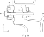
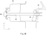
- Fig. 3A is a section IIIA-IIIA of Fig. 1B and Fig. 3B is a section IIIB-IIIB of Fig. 1B .
- the vehicular lamp fitting 10 of this embodiment is a vehicular head lamp and is mounted on both right and left sides of the front end of a vehicle (not shown) such as an automobile. Since the vehicular lamp fitting 10 mounted on the right and left sides has a symmetrical configuration, the vehicular lamp fitting 10 mounted on the right side (the right side toward the front of the vehicle) of the front end of the vehicle will be described as a representative.
- the XYZ axes are defined as shown in FIG. 1A etc.
- the X-axis extends in the longitudinal direction of the vehicle.
- the Y-axis extends in the vehicle width direction.
- the Z-axis extends in the vertical direction.
- the vehicular lamp fitting 10 has a reflector 20 and a housing 30.
- the reflector 20 holds both a light source 21 and a reflective surface 22 that controls light emitted by the light source 21.
- the light source 21 is, for example, a bulb light source such as a halogen bulb H4.
- the light source 21 may be a bulb light source other than a halogen bulb, for example, a HID lamp.
- the light source 21 is inserted into the bulb mounting hole H1 (see Fig. 2 ) that penetrates through the front and back of the reflector 20, and is detachably mounted on the reflector 20, in a positioned state with respect to the reflector 20 (the reflective surface 22), by a known fixing means.
- the reflective surface 22 is a reflective surface that controls the light emitted by the light source 21 and is formed on the front side of the reflector 20.
- the reflective surface 22 is composed as a reflective surface (so-called multi-reflector) that combines multiple divided reflective areas so that a low-beam light distribution pattern is formed when the low-beam filament of the light source 21 emits light and a high-beam light distribution pattern is formed when the high-beam filament emits light.
- the reflective surface 22 is formed, for example, by applying undercoat, aluminum deposition, and top coat to a resin base material (e.g., BMC substrates) in this order.
- the reflector 20 is attached to the housing 30 so as to be tiltable (aiming adjustable) in the up, down, left and right directions.
- the pivot portion 23a) of a pivot screw 23 attached to the back of the reflector 20 is rotatably held by a pivot holder 31 attached to the front of the housing 30.
- a first adjusting screw N1 inserted into a through hole H2 formed in the housing 30 is screwed to a first aiming nut 24 fixed to the back of the reflector 20. Note that the first adjusting screw N1 is attached to the housing 30 so as to rotate in the same position.
- Fig. 4 is a rear view of the reflector 20.
- the balloon B1 in Fig. 4 is an enlarged perspective view within the rectangle b1 in Fig. 4 .
- the balloon B2 in Fig. 4 is an enlarged perspective view within the rectangle b2 in Fig. 4 .
- the first aiming nut 24 is fixed at a portion of the back surface of the reflector 20 that is a predetermined distance to the right from the pivot screw 23.
- the straight line L1 passing through the pivot portion 23a and the first aiming nut 24 (the first adjusting screw N1) extends generally in the horizontal direction (Y direction).
- a second adjusting screw N2 inserted into a through hole H3 formed in the housing 30 is screwed to a second aiming nut 25 fixed to the back of the reflector 20. Note that the second adjusting screw N2 is attached to the housing 30 so as to rotate in the same position.
- the second aiming nut 25 is fixed at a portion of the back surface of the reflector 20 that is a predetermined distance downward from the pivot screw 23.
- the reflector 20 is arranged in an inclined state due to the installation space. Therefore, as shown in Fig. 5 , the straight line L2 passing through the pivot portion 23a and the second aiming nut 25 (the second adjusting screw N2) is inclined backward by an angle ⁇ 1 with respect to the vertical line Lv.
- Angle ⁇ 1 is, for example, 5 degrees. Note that ⁇ 1 may be 0 degrees.
- Fig. 5 shows that the straight line L2 passing through the pivot portion 23a and the second aiming nut 25 (the second adjusting screw N2) is inclined backward by an angle ⁇ 1 with respect to the vertical line L V .
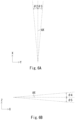
- Fig. 6A shows the aiming range (the angles ⁇ 2, ⁇ 3) in the left-right direction.
- the aiming in the left-right direction is performed by rotating the first adjusting screw N1 and changing the amount of screwing of the first adjusting screw N1 with respect to the first aiming nut 24.
- the reflector 20 is tilted (swung) about the straight line L2 passing through the pivot portion 23a and the second aiming nut 25 (the second adjusting screw N2) with the pivot portion 23a as a fulcrum within an angle ⁇ 2 (see Fig. 6A ) on the left side (left side toward the front of the vehicle) with respect to a reference axis AX.
- the reference axis AX extends in the X direction.
- ⁇ 2 is, for example, 2 degrees.
- the first adjusting screw N1 is rotated so that the amount of screwing to the first aiming nut 24 is increased.
- the reflector 20 is tilted (swung) about the straight line L2 passing through the pivot portion 23a and the second aiming nut 25 (the second adjusting screw N2) with the pivot portion 23a as a fulcrum within an angle ⁇ 3 (see Fig. 6A ) on the right side (left side toward the front of the vehicle) with respect to the reference axis AX.
- ⁇ 3 is, for example, 2 degrees.
- the aiming in the left-right direction is performed.
- Fig. 6B shows the aiming range (the angles ⁇ 4, ⁇ 5) in the up-down direction.
- the aiming in the up-down direction is performed by rotating the second adjusting screw N2 and changing the amount of screwing with respect to the second aiming nut 25.
- the reflector 20 is tilted (swung) about the straight line L1 passing through the pivot portion 23a and the first aiming nut 24 (the first adjusting screw N1) with the pivot portion 23a as a fulcrum within an angle ⁇ 4 (see Fig. 6B ) on the upper side with respect to the reference axis AX.
- ⁇ 4 is, for example, 2 degrees.
- the second adjusting screw N2 is rotated so that the amount of screwing to the second aiming nut 25 is increased.
- the reflector 20 is tilted (swung) about the straight line L1 passing through the pivot portion 23a and the first aiming nut 24 (the first adjusting screw N1) with the pivot portion 23a as a fulcrum within an angle ⁇ 5 (see Fig. 6B ) on the lower side with respect to the reference axis AX.
- ⁇ 5 is, for example, 2 degrees.
- a first cylindrical portion 26, a second cylindrical portion 27, a first slit portion 32, and a second slit portion 33 constitute the vibration suppression unit (a slider mechanism).
- the first cylindrical portion 26 and the second cylindrical portion 27 are provided on the back of the reflector 20.
- the first cylindrical portion 26 is provided on the straight line L1 passing through the pivot portion 23a and the first aiming nut 24 (the first adjusting screw N1) and in the vicinity of the first adjusting screw N1.
- the first cylindrical portion 26 extends in a direction (For example, in the Y direction) that intersects (For example, orthogonal) with the vibration direction (up-down direction) of the reflector 20.
- the first cylindrical portion 26 is supported by support portions 28a, 28b whose both ends portion in its axial direction extend from the back surface of the reflector 20 (see balloon B1 in Fig. 4 ).
- the first cylindrical portion 26, the support portions 28a, 28b, and the reflector 20 are integrally formed.
- the first cylindrical portion 26 may have a complete or incomplete cylindrical shape. In the present embodiment, for the convenience of the mold (in relation to the draft angle), the first cylindrical portion 26 is not a perfect cylindrical shape but an incomplete cylindrical shape.
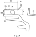
- Fig. 7A is a VIIA-VIIA section view of Fig. 1B .
- the first cylindrical portion 26 is arranged in the first slit portion 32 provided in the housing 30, as shown in Fig. 7A .
- the first slit portion 32 includes an upper portion 32a and a lower portion 32b extending in a direction (For example, in the Y direction) intersecting (For example, orthogonal) with respect to the vibration direction (up and down direction) of the reflector 20, and is a portion having a U-shaped cross section.
- the slit width W1 (the distance between the upper portion 32a and the lower portion 32b. See Fig. 7A ) of the first slit portion 32 is a value considered so that it is smaller than the amount of movement (the amount of movement in the Z direction) of the first cylindrical portion 26 due to the vibration (up-down direction vibration) of the reflector 20.
- the slit depth D1 of the first slit portion 32 is a value considered so that the first cylindrical portion 26 moves within the first slit portion 32 (That is, so that the first cylindrical portion 26 does not move out of the first slit portion 32.), even if the reflector 20 is inclined around the straight line L2 passing through the pivot portion 23a and the second aiming nut 25 (the second adjusting screw N2) with the pivot portion 23a as a fulcrum by the left-right direction aiming.
- the second cylindrical portion 27 is provided in the vicinity of the second adjusting screw N2.
- the second cylindrical portion 27, like the first cylindrical portion 26, extends in a direction (For example, in the Y direction) that intersects (For example, orthogonal) with the vibration direction (up-down direction) of the reflector 20.
- the second cylindrical portion 27 is supported by support portions 29a, 29b whose both ends portion in its axial direction extend from the back surface of the reflector 20 (see balloon B2 in Fig. 4 ).
- the second cylindrical portion 27, the support portions 29a, 29b, and the reflector 20 are integrally formed.
- the second cylindrical portion 27 may have a complete or incomplete cylindrical shape. In the present embodiment, for the convenience of the mold (in relation to the draft angle), the second cylindrical portion 27 is not a perfect cylindrical shape but an incomplete cylindrical shape.
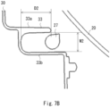
- Fig. 7B is a VIIB-VIIB section view of Fig. 1B .
- the second cylindrical portion 27 is arranged in the second slit portion 33 provided in the housing 30, as shown in Fig. 7B .
- the second slit portion 33 includes an upper portion 33a and a lower portion 33b extending in a direction (For example, in the Y direction) intersecting (For example, orthogonal) with respect to the vibration direction (up and down direction) of the reflector 20, and is a portion having a U-shaped cross section.
- the slit width W2 (the distance between the upper portion 33a and the lower portion 33b. See Fig. 7B ) of the second slit portion 33 is a value considered so that it is smaller than the amount of movement (the amount of movement in the Z direction) of the second cylindrical portion 27 due to the vibration (up-down direction vibration) of the reflector 20.
- the slit depth D2 of the second slit portion 33 is a value considered so that the second cylindrical portion 27 moves within the second slit portion 33 (That is, so that the second cylindrical portion 27 does not move out of the second slit portion 33.), even if the reflector 20 is inclined around the straight line L1 passing through the pivot portion 23a and the first aiming nut 24 (the first adjusting screw N1) with the pivot portion 23a as a fulcrum by up-down direction aiming.
- the upper portion 33a of the second slit portion 33 is shorter than the lower portion 33b for the convenience of the mold (in relation to the draft angle).
- the upper portion 33a of the second slit portion 33 may be shorter than the lower portion 33b because the vibration of the second cylindrical portion 27 side (vibration in up-down direction) of the reflector 20 is smaller than that of the first cylindrical portion 26 side (vibration in up-down direction) and the second cylindrical portion 27 and the second slit portion 33 are supplementary vibration measures.
- Figs 8 and 9 are diagrams for explaining the vibration suppression operation.
- 0 degree indicates the positional relationship between the first cylindrical portion 26 and the first slit portion 32 provided in the housing 30 in the reference state before aiming.
- 2 degree indicates the positional relationship between the first cylindrical portion 26 and the first slit portion 32 provided in the housing 30 in the state in which the reflector 20 is tilted (swung) at an angle ⁇ 2 (see FIG. 6A ) to the left side (left side toward the front of the vehicle) with respect to the reference axis AX around the straight line L2 passing through the pivot portion 23a and the second aiming nut 25 (the second adjusting screw N2) with the pivot portion 23a as a fulcrum.
- ⁇ 2 see FIG. 6A
- "-2 degree” indicates the positional relationship between the first cylindrical portion 26 and the first slit portion 32 provided in the housing 30 in the state in which the reflector 20 is tilted (swung) at an angle ⁇ 3 (see FIG. 6A ) to the right side (right side toward the front of the vehicle) with respect to the reference axis AX around the straight line L2 passing through the pivot portion 23a and the second aiming nut 25 (the second adjusting screw N2) with the pivot portion 23a as a fulcrum.
- FIG. 8 it can be seen that when aiming is performed in the left-right direction within the angles ⁇ 2 and ⁇ 3, the first cylindrical portion 26 moves within the first slit portion 32 (That is, the first cylindrical portion 26 does not move outside the first slit portion 32.). That is, when aiming is performed in the left-right direction within the angles ⁇ 2 and ⁇ 3, the first cylindrical portion 26 moves in a state sandwiched between the upper portion 32a and the lower portion 32b of the first slit portion 32.
- the vibrating first cylindrical portion 26 abuts on the first slit portion 32 (the upper 32a or the lower 32b). This suppresses the vibrations (vibrations in the up-down direction) of the reflector 20 (the first cylindrical portion 26).
- 0 degree indicates the positional relationship between the second cylindrical portion 27 and the second slit portion 33 provided in the housing 30 in the reference state before aiming.
- 2 degree indicates the positional relationship between the second cylindrical portion 27 and the second slit portion 33 provided in the housing 30 in the state in which the reflector 20 is tilted (swung) at an angle ⁇ 4 (see FIG. 6B ) upward with respect to the reference axis AX around the straight line L1 passing through the pivot portion 23a and the first aiming nut 24 (the first adjusting screw N1) with the pivot portion 23a as a fulcrum.
- Fig. 9 “0 degree” indicates the positional relationship between the second cylindrical portion 27 and the second slit portion 33 provided in the housing 30 in the reference state before aiming.
- 2 degree indicates the positional relationship between the second cylindrical portion 27 and the second slit portion 33 provided in the housing 30 in the state in which the reflector 20 is tilted (swung) at an angle ⁇ 4 (see FIG. 6B ) upward with respect
- "-2 degree” indicates the positional relationship between the second cylindrical portion 27 and the second slit portion 33 provided in the housing 30 in the state in which the reflector 20 is tilted (swung) at an angle ⁇ 5 (see FIG. 6B ) downward with respect to the reference axis AX around the straight line L1 passing through the pivot portion 23a and the first aiming nut 24 (the first adjusting screw N1) with the pivot portion 23a as a fulcrum.
- FIG. 9 it can be seen that when aiming is performed in the up-down direction within the angles ⁇ 4 and ⁇ 5, the second cylindrical portion 27 moves within the second slit portion 33 (That is, the second cylindrical portion 27 does not move outside the second slit portion 33.). That is, when aiming is performed in the left-right direction within the angles ⁇ 4 and ⁇ 5, the second cylindrical portion 27 moves in a state sandwiched between the upper portion 33a and the lower portion 33b of the second slit portion 33.
- the vibrating second cylindrical portion 27 abuts on the second slit portion 33 (the upper 33a or the lower 33b). This suppresses the vibrations (vibrations in the up-down direction) of the reflector 20 (the second cylindrical portion 27).
- the vibration of the reflector 20 (Vibration in the up-down direction that occurs when the vehicle is running, etc.) can be suppressed.
- the rigidity of the resin component involved in aiming of a reflector or the like is improved.
- the vibration suppression unit (a slider mechanism) that suppresses vibration (vibration in the up-down direction) of the reflector 20 with respect to the housing 30, namely the first cylindrical portion 26, the second cylindrical portion 27, the first slit portion 32, and the second slit portion 33, is provided, the first cylindrical portion 26 is arranged within the first slit portion 32, and the second cylindrical portion 27 is arranged within the second slit portion 33.
- the first aiming nut 24, the second aiming nut 25, and the like do not move more than necessary due to the vibration suppression unit (a slider mechanism), so that distortion is minimized. As a result, the damage to the first aiming nut 24 and the second aiming nut 25 is suppressed.
- a mounting ring 40 (also called a bracket) that holds both a light source (a semiconductor light emitting element such as an LED), an optical system (Low beam unit and high beam unit) such as a lens that controls the light emitted by the light source may be used.
- a light source a semiconductor light emitting element such as an LED
- an optical system Low beam unit and high beam unit
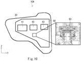
- Fig. 10 is an example of a vehicular lamp fitting 10A using the mounting ring 40 that holds three lenses 41, 42, and 43 that controls light emitted by a light source.
- a cylindrical portion extending in a direction (for example, the Z direction) that intersects (for example, orthogonally) with respect to the vibration direction and a slit portion extending in a direction (for example, the Z direction) that intersects (for example, orthogonally) with respect to the vibration direction, and having a U-shaped cross section may be used as the vibration suppression unit (a slider mechanism)(see Fig. 11).
- Fig. 11 is a cross section of XI-XI within the rectangle B3 in Fig.
- Fig. 11 is a cross section of C-C within the rectangle B3 in Fig. 10 .
- first cylindrical portion 26 and the second cylindrical portion 27
- first cylindrical portion 26 and the second cylindrical portion 27
- the first cylindrical portion 26 may be configured as a separate component from the reflector 20 and attached to the reflector 20 afterward.
- the vehicular lamp fitting of the present invention may also be applied to an LED headlamp (Projector type, reflector type, direct projection type).
Landscapes
- Engineering & Computer Science (AREA)
- General Engineering & Computer Science (AREA)
- Mechanical Engineering (AREA)
- Non-Portable Lighting Devices Or Systems Thereof (AREA)
- Lighting Device Outwards From Vehicle And Optical Signal (AREA)
- Securing Globes, Refractors, Reflectors Or The Like (AREA)
Abstract
Description
- The present invention relates to a vehicular lamp fitting, and in particular, to a vehicular lamp fitting capable of suppressing vibration of a reflector.
- A vehicular lamp fitting is known in which aiming is performed by connecting a reflector and a housing (lamp body) by a pivot portion (ball joint) and two adjusting screws (aiming screws), rotating each adjusting screw, and tilting the reflector up, down, left, and right with the pivot portion as a fulcrum (See, e.g., Patent Literature 1).
- [Patent Literature 1]
Japanese Unexamined Patent Application Publication No. 2002-193024 - However, in the Patent Document 1, since the reflector is supported at three positions of a pivot portion (ball joint) and two adjusting screws (aiming screws), vibration of the reflector (vibration that is occurred during vehicle travel, etc.) cannot be suppressed, and there is a problem that the rigidity of the resin component involved in aiming of a reflector or the like is reduced.
- An object of the present invention is to provide a vehicular lamp fitting capable of suppressing vibration of a reflector (vibration that is occurred during vehicle travel, etc.).
- A vehicular lamp fitting according to the present invention comprises a first holding member that holds both a light source and a light control member that controls light emitted by the light source; a second holding member that holds the first holding member so as to be tiltable in the up, down, left and right directions; a vibration suppression unit that suppresses vibration of the first holding member relative to the second holding member; and the vibration suppression unit comprising: a first portion provided on the first holding member; a second portion, which is provided on the second holding member and suppresses the vibration of the first holding member with respect to the second holding member by abutting the first portion vibrating in the vibration direction of the first holding member.
- By this configuration, it is possible to suppress vibration of a reflector (vibration that is occurred during vehicle travel, etc.).
- This is because the vibration suppression unit that suppresses vibration of the first holding member relative to the second holding member is provided.
- In the vehicular lamp fitting described above, a pivot portion provided on the first holding member; a pivot holder provided in the second holding member and rotatably holding the pivot portion; a first adjusting screw that tilts the first holding member in the left-right direction with the pivot portion as a fulcrum; and a second adjusting screw that tilts the first holding member in the up-down direction with the pivot portion as a fulcrum may be provided.
- Moreover, in the vehicular lamp fitting described above, the first portion may be provided in the vicinity of the first adjusting screw of the first holding member.
- Moreover, in the vehicular lamp fitting described above, the first portion may be provided in the vicinity of the second adjusting screw of the first holding member.
- Moreover, in the vehicular lamp fitting described above, the first portion may be a first cylindrical portion extending in a direction intersecting with the vibration direction of the first holding member, the second portion may be a slit portion having a U-shaped cross-sectional shape that extends in a direction intersecting the vibration direction of the first holding member, the first cylindrical portion may be arranged in the slit portion.
- According to the present invention, it is possible to provide a vehicular lamp fitting capable of suppressing vibration of a reflector (vibration that is occurred during vehicle travel, etc.).
-
-
Fig. 1A is a front view of the vehicular lamp fitting 10; -
Fig. 1B is a rear view; -
Fig. 2 is an exploded perspective view of the vehicular lamp fitting 10 (an outer lens, etc., omitted); -
Fig. 3A is a section IIIA-IIIA ofFig. 1B ; -
Fig. 3B is a section IIIB-IIIB ofFig. 1B ; -
Fig. 4 is a rear view of thereflector 20; -
Fig. 5 shows that the straight line L2 passing through thepivot portion 23a and the second aiming nut 25 (the second adjusting screw N2) is inclined backward by an angle θ1 with respect to the vertical line Lv; -
Fig. 6A shows the aiming range (the angles θ2, θ3) in the left-right direction; -
Fig. 6B shows the aiming range (the angles θ4, θ5) in the up-down direction; -
Fig. 7A is a VIIA-VIIA section view ofFig. 1B ; -
Fig. 7B is a VIIB-VIIB section view ofFig. 1B ; -
Fig 8 is a diagram for explaining the vibration suppression operation; -
Fig 9 is a diagram for explaining the vibration suppression operation; -
Fig. 10 is an example of a vehicular lamp fitting 10A using themounting ring 40 that holds threelenses -
Fig. 11 is a cross section of XI-XI within the rectangle B3 inFig. 10 . - A vehicular lamp fitting 10 according to an embodiment of the present invention will be described hereinafter with reference to the accompanying drawings. The same components are denoted by the same reference signs throughout the drawings, and redundant descriptions will be omitted.
-
Fig. 1A is a front view of the vehicular lamp fitting 10 andFig. 1B is a rear view.Fig. 2 is an exploded perspective view of the vehicular lamp fitting 10 (an outer lens, etc., omitted).Fig. 3A is a section IIIA-IIIA ofFig. 1B andFig. 3B is a section IIIB-IIIB ofFig. 1B . - The vehicular lamp fitting 10 of this embodiment is a vehicular head lamp and is mounted on both right and left sides of the front end of a vehicle (not shown) such as an automobile. Since the vehicular lamp fitting 10 mounted on the right and left sides has a symmetrical configuration, the vehicular lamp fitting 10 mounted on the right side (the right side toward the front of the vehicle) of the front end of the vehicle will be described as a representative. For convenience of explanation, the XYZ axes are defined as shown in
FIG. 1A etc. The X-axis extends in the longitudinal direction of the vehicle. The Y-axis extends in the vehicle width direction. The Z-axis extends in the vertical direction. - As shown in
Figs. 1A and2 , the vehicular lamp fitting 10 has areflector 20 and ahousing 30. - The
reflector 20 holds both alight source 21 and areflective surface 22 that controls light emitted by thelight source 21. - The
light source 21 is, for example, a bulb light source such as a halogen bulb H4. Note that thelight source 21 may be a bulb light source other than a halogen bulb, for example, a HID lamp. Thelight source 21 is inserted into the bulb mounting hole H1 (seeFig. 2 ) that penetrates through the front and back of thereflector 20, and is detachably mounted on thereflector 20, in a positioned state with respect to the reflector 20 (the reflective surface 22), by a known fixing means. - The
reflective surface 22 is a reflective surface that controls the light emitted by thelight source 21 and is formed on the front side of thereflector 20. Specifically, thereflective surface 22 is composed as a reflective surface (so-called multi-reflector) that combines multiple divided reflective areas so that a low-beam light distribution pattern is formed when the low-beam filament of thelight source 21 emits light and a high-beam light distribution pattern is formed when the high-beam filament emits light. Thereflective surface 22 is formed, for example, by applying undercoat, aluminum deposition, and top coat to a resin base material (e.g., BMC substrates) in this order. - The
reflector 20 is attached to thehousing 30 so as to be tiltable (aiming adjustable) in the up, down, left and right directions. Specifically, although not shown, thehead 23a (A spherical portion. Hereafter referred to as thepivot portion 23a) of apivot screw 23 attached to the back of thereflector 20 is rotatably held by apivot holder 31 attached to the front of thehousing 30. - As shown in
Fig. 3A , a first adjusting screw N1 inserted into a through hole H2 formed in thehousing 30 is screwed to a first aimingnut 24 fixed to the back of thereflector 20. Note that the first adjusting screw N1 is attached to thehousing 30 so as to rotate in the same position. -
Fig. 4 is a rear view of thereflector 20. The balloon B1 inFig. 4 is an enlarged perspective view within the rectangle b1 inFig. 4 . The balloon B2 inFig. 4 is an enlarged perspective view within the rectangle b2 inFig. 4 . - As shown in
Fig. 4 , the first aimingnut 24 is fixed at a portion of the back surface of thereflector 20 that is a predetermined distance to the right from thepivot screw 23. The straight line L1 passing through thepivot portion 23a and the first aiming nut 24 (the first adjusting screw N1) extends generally in the horizontal direction (Y direction). - As shown in
Fig. 3B , a second adjusting screw N2 inserted into a through hole H3 formed in thehousing 30 is screwed to a second aimingnut 25 fixed to the back of thereflector 20. Note that the second adjusting screw N2 is attached to thehousing 30 so as to rotate in the same position. - As shown in
Fig. 4 , the second aimingnut 25 is fixed at a portion of the back surface of thereflector 20 that is a predetermined distance downward from thepivot screw 23. Note that thereflector 20 is arranged in an inclined state due to the installation space. Therefore, as shown inFig. 5 , the straight line L2 passing through thepivot portion 23a and the second aiming nut 25 (the second adjusting screw N2) is inclined backward by an angle θ1 with respect to the vertical line Lv. Angle θ1 is, for example, 5 degrees. Note that θ1 may be 0 degrees.Fig. 5 shows that the straight line L2 passing through thepivot portion 23a and the second aiming nut 25 (the second adjusting screw N2) is inclined backward by an angle θ1 with respect to the vertical line LV. - Next, the aiming operation will be described.
- First, the aiming operation in the left-right direction will be described.
-
Fig. 6A shows the aiming range (the angles θ2, θ3) in the left-right direction. - The aiming in the left-right direction is performed by rotating the first adjusting screw N1 and changing the amount of screwing of the first adjusting screw N1 with respect to the first aiming
nut 24. - For example, assume that the first adjusting screw N1 is rotated so that the amount of screwing to the first aiming
nut 24 is reduced. In this case, in accordance with the amount of rotation of the first adjusting screw N1 (the amount of screwing with respect to the first aiming nut 24), thereflector 20 is tilted (swung) about the straight line L2 passing through thepivot portion 23a and the second aiming nut 25 (the second adjusting screw N2) with thepivot portion 23a as a fulcrum within an angle θ2 (seeFig. 6A ) on the left side (left side toward the front of the vehicle) with respect to a reference axis AX. The reference axis AX extends in the X direction. θ2 is, for example, 2 degrees. - On the other hand, assume that the first adjusting screw N1 is rotated so that the amount of screwing to the first aiming
nut 24 is increased. In this case, in accordance with the amount of rotation of the first adjusting screw N1 (the amount of screwing with respect to the first aiming nut 24), thereflector 20 is tilted (swung) about the straight line L2 passing through thepivot portion 23a and the second aiming nut 25 (the second adjusting screw N2) with thepivot portion 23a as a fulcrum within an angle θ3 (seeFig. 6A ) on the right side (left side toward the front of the vehicle) with respect to the reference axis AX. θ3 is, for example, 2 degrees. - As described above, by rotating the first adjusting screw N1 and changing the amount of screwing of the first adjusting screw N1 with respect to the first aiming
nut 24, the aiming in the left-right direction is performed. - Next, the aiming operation in the up-down direction will be described.
-
Fig. 6B shows the aiming range (the angles θ4, θ5) in the up-down direction. - The aiming in the up-down direction is performed by rotating the second adjusting screw N2 and changing the amount of screwing with respect to the second aiming
nut 25. - For example, assume that the second adjusting screw N2 is rotated so that the amount of screwing to the second aiming
nut 25 is reduced. In this case, in accordance with the amount of rotation of the second adjusting screw N2 (the amount of screwing with respect to the second aiming nut 25), thereflector 20 is tilted (swung) about the straight line L1 passing through thepivot portion 23a and the first aiming nut 24 (the first adjusting screw N1) with thepivot portion 23a as a fulcrum within an angle θ4 (seeFig. 6B ) on the upper side with respect to the reference axis AX. θ4 is, for example, 2 degrees. - On the other hand, assume that the second adjusting screw N2 is rotated so that the amount of screwing to the second aiming
nut 25 is increased. In this case, in accordance with the amount of rotation of the second adjusting screw N2 (the amount of screwing with respect to the second aiming nut 25), thereflector 20 is tilted (swung) about the straight line L1 passing through thepivot portion 23a and the first aiming nut 24 (the first adjusting screw N1) with thepivot portion 23a as a fulcrum within an angle θ5 (seeFig. 6B ) on the lower side with respect to the reference axis AX. θ5 is, for example, 2 degrees. - As described above, by rotating the second adjusting screw N2 and changing the amount of screwing of the second adjusting screw N2 with respect to the second aiming
nut 25, the aiming in the up-down direction is performed. - Next, a configuration (a configuration of the vibration suppression unit) to suppress the vibration (up-down vibration in
Fig. 3 ) of thereflector 20 will be described. A firstcylindrical portion 26, a secondcylindrical portion 27, afirst slit portion 32, and asecond slit portion 33 constitute the vibration suppression unit (a slider mechanism). - As shown in
Fig. 4 , the firstcylindrical portion 26 and the secondcylindrical portion 27 are provided on the back of thereflector 20. - The first
cylindrical portion 26 is provided on the straight line L1 passing through thepivot portion 23a and the first aiming nut 24 (the first adjusting screw N1) and in the vicinity of the first adjusting screw N1. The firstcylindrical portion 26 extends in a direction (For example, in the Y direction) that intersects (For example, orthogonal) with the vibration direction (up-down direction) of thereflector 20. The firstcylindrical portion 26 is supported bysupport portions Fig. 4 ). Note that the firstcylindrical portion 26, thesupport portions reflector 20 are integrally formed. Note that the firstcylindrical portion 26 may have a complete or incomplete cylindrical shape. In the present embodiment, for the convenience of the mold (in relation to the draft angle), the firstcylindrical portion 26 is not a perfect cylindrical shape but an incomplete cylindrical shape. -
Fig. 7A is a VIIA-VIIA section view ofFig. 1B . - With the
reflector 20 attached to thehousing 30 so as to tilt up, down, left and right directions, the firstcylindrical portion 26 is arranged in thefirst slit portion 32 provided in thehousing 30, as shown inFig. 7A . - The
first slit portion 32 includes anupper portion 32a and alower portion 32b extending in a direction (For example, in the Y direction) intersecting (For example, orthogonal) with respect to the vibration direction (up and down direction) of thereflector 20, and is a portion having a U-shaped cross section. - The slit width W1 (the distance between the
upper portion 32a and thelower portion 32b. SeeFig. 7A ) of thefirst slit portion 32 is a value considered so that it is smaller than the amount of movement (the amount of movement in the Z direction) of the firstcylindrical portion 26 due to the vibration (up-down direction vibration) of thereflector 20. - In addition, the slit depth D1 of the first slit portion 32 (see
Fig. 7A ) is a value considered so that the firstcylindrical portion 26 moves within the first slit portion 32 (That is, so that the firstcylindrical portion 26 does not move out of thefirst slit portion 32.), even if thereflector 20 is inclined around the straight line L2 passing through thepivot portion 23a and the second aiming nut 25 (the second adjusting screw N2) with thepivot portion 23a as a fulcrum by the left-right direction aiming. - As shown in
Fig. 4 , the secondcylindrical portion 27 is provided in the vicinity of the second adjusting screw N2. The secondcylindrical portion 27, like the firstcylindrical portion 26, extends in a direction (For example, in the Y direction) that intersects (For example, orthogonal) with the vibration direction (up-down direction) of thereflector 20. The secondcylindrical portion 27 is supported bysupport portions Fig. 4 ). Note that the secondcylindrical portion 27, thesupport portions reflector 20 are integrally formed. Note that the secondcylindrical portion 27 may have a complete or incomplete cylindrical shape. In the present embodiment, for the convenience of the mold (in relation to the draft angle), the secondcylindrical portion 27 is not a perfect cylindrical shape but an incomplete cylindrical shape. -
Fig. 7B is a VIIB-VIIB section view ofFig. 1B . - With the
reflector 20 attached to thehousing 30 so as to tilt up, down, left and right directions, the secondcylindrical portion 27 is arranged in thesecond slit portion 33 provided in thehousing 30, as shown inFig. 7B . - The
second slit portion 33 includes anupper portion 33a and alower portion 33b extending in a direction (For example, in the Y direction) intersecting (For example, orthogonal) with respect to the vibration direction (up and down direction) of thereflector 20, and is a portion having a U-shaped cross section. - The slit width W2 (the distance between the
upper portion 33a and thelower portion 33b. SeeFig. 7B ) of thesecond slit portion 33 is a value considered so that it is smaller than the amount of movement (the amount of movement in the Z direction) of the secondcylindrical portion 27 due to the vibration (up-down direction vibration) of thereflector 20. - In addition, the slit depth D2 of the second slit portion 33 (see
Fig. 7B ) is a value considered so that the secondcylindrical portion 27 moves within the second slit portion 33 (That is, so that the secondcylindrical portion 27 does not move out of thesecond slit portion 33.), even if thereflector 20 is inclined around the straight line L1 passing through thepivot portion 23a and the first aiming nut 24 (the first adjusting screw N1) with thepivot portion 23a as a fulcrum by up-down direction aiming. However, in this embodiment, theupper portion 33a of thesecond slit portion 33 is shorter than thelower portion 33b for the convenience of the mold (in relation to the draft angle). Note that theupper portion 33a of thesecond slit portion 33 may be shorter than thelower portion 33b because the vibration of the secondcylindrical portion 27 side (vibration in up-down direction) of thereflector 20 is smaller than that of the firstcylindrical portion 26 side (vibration in up-down direction) and the secondcylindrical portion 27 and thesecond slit portion 33 are supplementary vibration measures. - Next, vibration suppression operation will be described.
-
Figs 8 and 9 are diagrams for explaining the vibration suppression operation. - In
Fig. 8 , "0 degree" indicates the positional relationship between the firstcylindrical portion 26 and thefirst slit portion 32 provided in thehousing 30 in the reference state before aiming. InFig. 8 , "2 degree" indicates the positional relationship between the firstcylindrical portion 26 and thefirst slit portion 32 provided in thehousing 30 in the state in which thereflector 20 is tilted (swung) at an angle θ2 (seeFIG. 6A ) to the left side (left side toward the front of the vehicle) with respect to the reference axis AX around the straight line L2 passing through thepivot portion 23a and the second aiming nut 25 (the second adjusting screw N2) with thepivot portion 23a as a fulcrum. InFig. 8 , "-2 degree" indicates the positional relationship between the firstcylindrical portion 26 and thefirst slit portion 32 provided in thehousing 30 in the state in which thereflector 20 is tilted (swung) at an angle θ3 (seeFIG. 6A ) to the right side (right side toward the front of the vehicle) with respect to the reference axis AX around the straight line L2 passing through thepivot portion 23a and the second aiming nut 25 (the second adjusting screw N2) with thepivot portion 23a as a fulcrum. - Referring to
Fig. 8 , it can be seen that when aiming is performed in the left-right direction within the angles θ2 and θ3, the firstcylindrical portion 26 moves within the first slit portion 32 (That is, the firstcylindrical portion 26 does not move outside thefirst slit portion 32.). That is, when aiming is performed in the left-right direction within the angles θ2 and θ3, the firstcylindrical portion 26 moves in a state sandwiched between theupper portion 32a and thelower portion 32b of thefirst slit portion 32. - Thus, when the reflector 20 (the first cylindrical portion 26) vibrates (vibrates in the up-down direction), the vibrating first
cylindrical portion 26 abuts on the first slit portion 32 (the upper 32a or the lower 32b). This suppresses the vibrations (vibrations in the up-down direction) of the reflector 20 (the first cylindrical portion 26). - In
Fig. 9 , "0 degree" indicates the positional relationship between the secondcylindrical portion 27 and thesecond slit portion 33 provided in thehousing 30 in the reference state before aiming. InFig. 9 , "2 degree" indicates the positional relationship between the secondcylindrical portion 27 and thesecond slit portion 33 provided in thehousing 30 in the state in which thereflector 20 is tilted (swung) at an angle θ4 (seeFIG. 6B ) upward with respect to the reference axis AX around the straight line L1 passing through thepivot portion 23a and the first aiming nut 24 (the first adjusting screw N1) with thepivot portion 23a as a fulcrum. InFig. 9 , "-2 degree" indicates the positional relationship between the secondcylindrical portion 27 and thesecond slit portion 33 provided in thehousing 30 in the state in which thereflector 20 is tilted (swung) at an angle θ5 (seeFIG. 6B ) downward with respect to the reference axis AX around the straight line L1 passing through thepivot portion 23a and the first aiming nut 24 (the first adjusting screw N1) with thepivot portion 23a as a fulcrum. - Referring to
Fig. 9 , it can be seen that when aiming is performed in the up-down direction within the angles θ4 and θ5, the secondcylindrical portion 27 moves within the second slit portion 33 (That is, the secondcylindrical portion 27 does not move outside thesecond slit portion 33.). That is, when aiming is performed in the left-right direction within the angles θ4 and θ5, the secondcylindrical portion 27 moves in a state sandwiched between theupper portion 33a and thelower portion 33b of thesecond slit portion 33. - Thus, when the reflector 20 (the second cylindrical portion 27) vibrates (vibrates in the up-down direction), the vibrating second
cylindrical portion 27 abuts on the second slit portion 33 (the upper 33a or the lower 33b). This suppresses the vibrations (vibrations in the up-down direction) of the reflector 20 (the second cylindrical portion 27). - As described above, according to the present embodiment, the vibration of the reflector 20 (Vibration in the up-down direction that occurs when the vehicle is running, etc.) can be suppressed. As a result, the rigidity of the resin component involved in aiming of a reflector or the like is improved.
- This is due to the fact that the vibration suppression unit (a slider mechanism) that suppresses vibration (vibration in the up-down direction) of the
reflector 20 with respect to thehousing 30, namely the firstcylindrical portion 26, the secondcylindrical portion 27, thefirst slit portion 32, and thesecond slit portion 33, is provided, the firstcylindrical portion 26 is arranged within thefirst slit portion 32, and the secondcylindrical portion 27 is arranged within thesecond slit portion 33. Although there is no apparent movement (almost no movement) during vibration in the up-down, distortion occurs in the first aimingnut 24 and the second aimingnut 25. In contrast, according to the present embodiment, the first aimingnut 24, the second aimingnut 25, and the like do not move more than necessary due to the vibration suppression unit (a slider mechanism), so that distortion is minimized. As a result, the damage to the first aimingnut 24 and the second aimingnut 25 is suppressed. - Next, a variation is described.
- In the above embodiment, an example using the
reflector 20 that holds both the light source 21 (a bulb light source) and thereflective surface 22 that controls the light emitted by thelight source 21 as the first holding member was described, but this is not limited to the above. - For example, as the first holding member, a mounting ring 40 (also called a bracket) that holds both a light source (a semiconductor light emitting element such as an LED), an optical system (Low beam unit and high beam unit) such as a lens that controls the light emitted by the light source may be used.
-
Fig. 10 is an example of a vehicular lamp fitting 10A using the mountingring 40 that holds threelenses - In addition, in the above embodiment, when the vibration (vibration in the up-down direction) of the
reflector 20 is suppressed, an example in which the first cylindrical portion 26 (and the second cylindrical portion 27) extending in a direction (for example, the Y direction) that intersects (for example, orthogonally) with respect to the vibration direction and the first slit portion 32 (and the second slit portion 33) extending in a direction (for example, the Y direction) that intersects (for example, orthogonally) with respect to the vibration direction, and having a U-shaped cross section are used as the vibration suppression unit (a slider mechanism) has been described, but this is not limited to the above. - For example, when the vibration (vibration in the left-right direction) of the
reflector 20 is suppressed, a cylindrical portion extending in a direction (for example, the Z direction) that intersects (for example, orthogonally) with respect to the vibration direction and a slit portion extending in a direction (for example, the Z direction) that intersects (for example, orthogonally) with respect to the vibration direction, and having a U-shaped cross section may be used as the vibration suppression unit (a slider mechanism)(seeFig. 11). Fig. 11 is a cross section of XI-XI within the rectangle B3 inFig. 10 , and is an example using acylindrical portion 26A extending in a direction (for example, the Z direction) that intersects (for example, orthogonally) with respect to the vibration (vibration in the left-right direction) direction of thereflector 20 and aslit portion 32A extending in a direction (for example, the Z direction) that intersects (for example, orthogonally) with respect to the vibration direction, and having a U-shaped cross section.Fig. 11 is a cross section of C-C within the rectangle B3 inFig. 10 . - In the above embodiment, the example in which the first cylindrical portion 26 (and the second cylindrical portion 27) are integrally formed with the
reflector 20 was described, but this is not limited to the above. For example, the first cylindrical portion 26 (and the second cylindrical portion 27) may be configured as a separate component from thereflector 20 and attached to thereflector 20 afterward. - The vehicular lamp fitting of the present invention may also be applied to an LED headlamp (Projector type, reflector type, direct projection type).
- The numerical values shown in the above-described each embodiment is all given by way of example, and it is obvious that appropriate different numerical values can be used instead.
- The above-described each embodiment is, in every respect, merely an example. The present invention should not be limited by the description of the above-described each embodiment. The present invention can be implemented in other various ways without departing from its spirit or major characteristics.
- This application is based upon and claims the benefit of priority from
Japanese patent application No. 2021-051032, filed on March 25, 2021 -
- 10, 10A
- VEHICULAR LAMP FITTING
- 20
- REFLECTOR
- 21
- LIGHT SOURCE
- 22
- REFLECTIVE SURFACES
- 23
- PIVOT SCREW
- 23a
- HEAD (PIVOT PORTION)
- 24
- FIRST AIMING NUT
- 25
- SECOND AIMING NUT
- 26
- FIRST CYLINDRICAL PORTION
- 26A
- CYLINDRICAL PORTION
- 27
- SECOND CYLINDRICAL PORTION
- 28a, 28b
- SUPPORT PORTION
- 29a, 29b
- SUPPORT PORTION
- 30
- HOUSING
- 31
- PIVOT HOLDER
- 32
- FIRST SLIT PORTION
- 32A
- SLIT PORTION
- 32a
- UPPER PORTION
- 32b
- LOWER PORTION
- 33
- SECOND SLIT PORTION
- 33a
- UPPER PORTION
- 33b
- LOWER PORTION
- 40
- MOUNTING RING
- 41-43
- LENS
- AX
- REFERENCE AXIS
- B1, B2
- BALLOON
- D1, D2
- SLIT DEPTH
- H1
- BULB MOUNTING HOLE
- H2, H3
- THROUGH HOLE
- N1
- FIRST ADJUSTING SCREW
- N2
- SECOND ADJUSTING SCREW
- W1, W2
- SLIT WIDTH
Claims (5)
- A vehicular lamp fitting comprising:a first holding member that holds both a light source and a light control member that controls light emitted by the light source;a second holding member that holds the first holding member so as to be tiltable in the up, down, left and right directions; anda vibration suppression unit that suppresses vibration of the first holding member relative to the second holding member; whereinthe vibration suppression unit comprising:a first portion provided on the first holding member;a second portion, which is provided on the second holding member and suppresses the vibration of the first holding member with respect to the second holding member by abutting the first portion vibrating in the vibration direction of the first holding member.
- The vehicular lamp fitting according to claim 1 further comprising:a pivot portion provided on the first holding member;a pivot holder provided in the second holding member and rotatably holding the pivot portion;a first adjusting screw that tilts the first holding member in the left-right direction with the pivot portion as a fulcrum; anda second adjusting screw that tilts the first holding member in the up-down direction with the pivot portion as a fulcrum.
- The vehicular lamp fitting according to claim 1 or 2, wherein
the first portion is provided in the vicinity of the first adjusting screw of the first holding member. - The vehicular lamp fitting according to any one of claims 1 to 3, wherein
the first portion is provided in the vicinity of the second adjusting screw of the first holding member. - The vehicular lamp fitting according to any one of claims 1 to 4, whereinthe first portion is a first cylindrical portion extending in a direction intersecting with the vibration direction of the first holding member,the second portion is a slit portion having a U-shaped cross-sectional shape that extends in a direction intersecting the vibration direction of the first holding member, andthe first cylindrical portion is arranged in the slit portion.
Applications Claiming Priority (2)
| Application Number | Priority Date | Filing Date | Title |
|---|---|---|---|
| JP2021051032A JP7597625B2 (en) | 2021-03-25 | 2021-03-25 | Vehicle lighting fixtures |
| PCT/JP2022/013750 WO2022202946A1 (en) | 2021-03-25 | 2022-03-23 | Vehicle lamp |
Publications (3)
| Publication Number | Publication Date |
|---|---|
| EP4317770A1 true EP4317770A1 (en) | 2024-02-07 |
| EP4317770A4 EP4317770A4 (en) | 2025-01-29 |
| EP4317770B1 EP4317770B1 (en) | 2026-02-25 |
Family
ID=83395690
Family Applications (1)
| Application Number | Title | Priority Date | Filing Date |
|---|---|---|---|
| EP22775728.3A Active EP4317770B1 (en) | 2021-03-25 | 2022-03-23 | Vehicle lamp |
Country Status (5)
| Country | Link |
|---|---|
| US (1) | US12038146B2 (en) |
| EP (1) | EP4317770B1 (en) |
| JP (1) | JP7597625B2 (en) |
| CN (1) | CN117043510A (en) |
| WO (1) | WO2022202946A1 (en) |
Family Cites Families (14)
| Publication number | Priority date | Publication date | Assignee | Title |
|---|---|---|---|---|
| JP2632116B2 (en) | 1992-09-10 | 1997-07-23 | スタンレー電気株式会社 | Vehicle lighting |
| JP2002193023A (en) * | 2000-12-28 | 2002-07-10 | Koito Mfg Co Ltd | Reflector movable type car headlamp |
| JP3718124B2 (en) | 2000-12-28 | 2005-11-16 | 株式会社小糸製作所 | Reflector movable automotive headlamp |
| JP3888672B2 (en) * | 2001-12-25 | 2007-03-07 | 株式会社小糸製作所 | Reflector movable automotive headlamp |
| JP3897159B2 (en) | 2002-03-15 | 2007-03-22 | 株式会社小糸製作所 | Reflector movable headlamp |
| JP2004349095A (en) * | 2003-05-22 | 2004-12-09 | Ntn Corp | Headlight drive |
| JP4222905B2 (en) | 2003-08-01 | 2009-02-12 | 株式会社小糸製作所 | Automotive headlamps |
| JP5350023B2 (en) * | 2009-03-04 | 2013-11-27 | 株式会社小糸製作所 | Vehicle headlamp |
| JP5430225B2 (en) * | 2009-05-21 | 2014-02-26 | 株式会社小糸製作所 | Vehicle lighting |
| DE102012100459A1 (en) * | 2012-01-20 | 2013-07-25 | Hella Kgaa Hueck & Co. | Device for mounting support frame in housing of headlamp for vehicle, has holding element for pivotable mounting of support frame, and spring element for compensation of unfavorable positions of center of gravity of support frame |
| CZ303955B6 (en) * | 2012-04-19 | 2013-07-10 | Hella Autotechnik, S.R.O. | Headlight, especially motor vehicle headlight |
| US9475421B2 (en) * | 2013-10-23 | 2016-10-25 | Burton Technologies, Llc | Reflector damper bracket |
| FR3027655A1 (en) * | 2014-10-24 | 2016-04-29 | Valeo Vision | AUTOMOTIVE PROJECTOR WITH VISCOELASTIC DAMPING |
| JP7307520B2 (en) | 2019-09-26 | 2023-07-12 | 第一実業ビスウィル株式会社 | Appearance inspection device for circular products |
-
2021
- 2021-03-25 JP JP2021051032A patent/JP7597625B2/en active Active
-
2022
- 2022-03-23 CN CN202280023016.7A patent/CN117043510A/en active Pending
- 2022-03-23 US US18/552,122 patent/US12038146B2/en active Active
- 2022-03-23 EP EP22775728.3A patent/EP4317770B1/en active Active
- 2022-03-23 WO PCT/JP2022/013750 patent/WO2022202946A1/en not_active Ceased
Also Published As
| Publication number | Publication date |
|---|---|
| WO2022202946A1 (en) | 2022-09-29 |
| EP4317770B1 (en) | 2026-02-25 |
| JP2022149077A (en) | 2022-10-06 |
| EP4317770A4 (en) | 2025-01-29 |
| CN117043510A (en) | 2023-11-10 |
| US20240175562A1 (en) | 2024-05-30 |
| JP7597625B2 (en) | 2024-12-10 |
| US12038146B2 (en) | 2024-07-16 |
Similar Documents
| Publication | Publication Date | Title |
|---|---|---|
| US10807514B2 (en) | Vehicular lamp | |
| KR100992416B1 (en) | Headlights for vehicles | |
| JP2002216506A (en) | Vehicle headlights | |
| US20140321132A1 (en) | Vehicle lamp | |
| JP2001236802A (en) | Vehicle headlights | |
| JP2750645B2 (en) | Aiming adjustment device for automotive headlights | |
| CN111565974A (en) | Adjustment system for pivoting at least one optically relevant component of a vehicle headlight about a first axis and a second axis | |
| EP4317770B1 (en) | Vehicle lamp | |
| JP2023536890A (en) | automotive floodlight | |
| JP2003178609A (en) | Vehicle headlights | |
| JP4803166B2 (en) | Vehicle lighting | |
| JP2013089410A (en) | Vehicle headlight | |
| US7144141B2 (en) | Self-aim vehicle light device | |
| EP3995360B1 (en) | Vehicular lighting fixture | |
| JP2024131522A (en) | Vehicle lighting fixtures | |
| JP2020064840A (en) | Vehicle lighting | |
| WO2025187611A1 (en) | Nut member and optical axis adjustment mechanism | |
| JP2663312B2 (en) | Headlights for vehicles | |
| JP2632105B2 (en) | Headlights for vehicles | |
| JP2025008490A (en) | Vehicle lighting fixtures | |
| JP2002260414A (en) | Vehicle headlights | |
| JP2025137262A (en) | Optical components and optical axis adjustment mechanism | |
| CN120752474A (en) | Vehicle lighting | |
| WO2023248773A1 (en) | Road surface rendering device for vehicle | |
| JP2025124259A (en) | Vehicle lighting fixtures |
Legal Events
| Date | Code | Title | Description |
|---|---|---|---|
| STAA | Information on the status of an ep patent application or granted ep patent |
Free format text: STATUS: THE INTERNATIONAL PUBLICATION HAS BEEN MADE |
|
| PUAI | Public reference made under article 153(3) epc to a published international application that has entered the european phase |
Free format text: ORIGINAL CODE: 0009012 |
|
| STAA | Information on the status of an ep patent application or granted ep patent |
Free format text: STATUS: REQUEST FOR EXAMINATION WAS MADE |
|
| 17P | Request for examination filed |
Effective date: 20230925 |
|
| AK | Designated contracting states |
Kind code of ref document: A1 Designated state(s): AL AT BE BG CH CY CZ DE DK EE ES FI FR GB GR HR HU IE IS IT LI LT LU LV MC MK MT NL NO PL PT RO RS SE SI SK SM TR |
|
| DAV | Request for validation of the european patent (deleted) | ||
| DAX | Request for extension of the european patent (deleted) | ||
| REG | Reference to a national code |
Ref country code: DE Ipc: B60Q0001060000 Ref country code: DE Ref legal event code: R079 Ref document number: 602022031191 Country of ref document: DE Free format text: PREVIOUS MAIN CLASS: F21S0041675000 Ipc: B60Q0001060000 |
|
| A4 | Supplementary search report drawn up and despatched |
Effective date: 20250108 |
|
| RIC1 | Information provided on ipc code assigned before grant |
Ipc: F21W 102/13 20180101ALI20241223BHEP Ipc: F21S 45/10 20180101ALI20241223BHEP Ipc: F21S 41/675 20180101ALI20241223BHEP Ipc: F21S 41/39 20180101ALI20241223BHEP Ipc: B60Q 1/06 20060101AFI20241223BHEP |
|
| GRAP | Despatch of communication of intention to grant a patent |
Free format text: ORIGINAL CODE: EPIDOSNIGR1 |
|
| STAA | Information on the status of an ep patent application or granted ep patent |
Free format text: STATUS: GRANT OF PATENT IS INTENDED |
|
| RIC1 | Information provided on ipc code assigned before grant |
Ipc: B60Q 1/06 20060101AFI20250921BHEP Ipc: F21S 41/39 20180101ALI20250921BHEP Ipc: F21S 41/675 20180101ALI20250921BHEP Ipc: F21S 45/10 20180101ALI20250921BHEP Ipc: F21W 102/13 20180101ALI20250921BHEP |
|
| INTG | Intention to grant announced |
Effective date: 20251008 |
|
| GRAS | Grant fee paid |
Free format text: ORIGINAL CODE: EPIDOSNIGR3 |
|
| GRAA | (expected) grant |
Free format text: ORIGINAL CODE: 0009210 |
|
| STAA | Information on the status of an ep patent application or granted ep patent |
Free format text: STATUS: THE PATENT HAS BEEN GRANTED |
|
| AK | Designated contracting states |
Kind code of ref document: B1 Designated state(s): AL AT BE BG CH CY CZ DE DK EE ES FI FR GB GR HR HU IE IS IT LI LT LU LV MC MK MT NL NO PL PT RO RS SE SI SK SM TR |
|
| REG | Reference to a national code |
Ref country code: CH Ref legal event code: F10 Free format text: ST27 STATUS EVENT CODE: U-0-0-F10-F00 (AS PROVIDED BY THE NATIONAL OFFICE) Effective date: 20260225 Ref country code: GB Ref legal event code: FG4D |
|
| REG | Reference to a national code |
Ref country code: DE Ref legal event code: R096 Ref document number: 602022031191 Country of ref document: DE |
|
| REG | Reference to a national code |
Ref country code: IE Ref legal event code: FG4D |
|
| PGFP | Annual fee paid to national office [announced via postgrant information from national office to epo] |
Ref country code: AT Payment date: 20260301 Year of fee payment: 5 |
|
| REG | Reference to a national code |
Ref country code: NL Ref legal event code: MP Effective date: 20260225 |
|
| PG25 | Lapsed in a contracting state [announced via postgrant information from national office to epo] |
Ref country code: RS Free format text: LAPSE BECAUSE OF FAILURE TO SUBMIT A TRANSLATION OF THE DESCRIPTION OR TO PAY THE FEE WITHIN THE PRESCRIBED TIME-LIMIT Effective date: 20260525 |
|
| PG25 | Lapsed in a contracting state [announced via postgrant information from national office to epo] |
Ref country code: ES Free format text: LAPSE BECAUSE OF FAILURE TO SUBMIT A TRANSLATION OF THE DESCRIPTION OR TO PAY THE FEE WITHIN THE PRESCRIBED TIME-LIMIT Effective date: 20260225 |
|
| PG25 | Lapsed in a contracting state [announced via postgrant information from national office to epo] |
Ref country code: PL Free format text: LAPSE BECAUSE OF FAILURE TO SUBMIT A TRANSLATION OF THE DESCRIPTION OR TO PAY THE FEE WITHIN THE PRESCRIBED TIME-LIMIT Effective date: 20260225 |
|
| PG25 | Lapsed in a contracting state [announced via postgrant information from national office to epo] |
Ref country code: GR Free format text: LAPSE BECAUSE OF FAILURE TO SUBMIT A TRANSLATION OF THE DESCRIPTION OR TO PAY THE FEE WITHIN THE PRESCRIBED TIME-LIMIT Effective date: 20260526 |
|
| REG | Reference to a national code |
Ref country code: LT Ref legal event code: MG9D |
|
| PG25 | Lapsed in a contracting state [announced via postgrant information from national office to epo] |
Ref country code: LT Free format text: LAPSE BECAUSE OF FAILURE TO SUBMIT A TRANSLATION OF THE DESCRIPTION OR TO PAY THE FEE WITHIN THE PRESCRIBED TIME-LIMIT Effective date: 20260225 |
|
| PGFP | Annual fee paid to national office [announced via postgrant information from national office to epo] |
Ref country code: DE Payment date: 20260331 Year of fee payment: 5 |
|
| PG25 | Lapsed in a contracting state [announced via postgrant information from national office to epo] |
Ref country code: NO Free format text: LAPSE BECAUSE OF FAILURE TO SUBMIT A TRANSLATION OF THE DESCRIPTION OR TO PAY THE FEE WITHIN THE PRESCRIBED TIME-LIMIT Effective date: 20260525 |
|
| PG25 | Lapsed in a contracting state [announced via postgrant information from national office to epo] |
Ref country code: AT Free format text: LAPSE BECAUSE OF FAILURE TO SUBMIT A TRANSLATION OF THE DESCRIPTION OR TO PAY THE FEE WITHIN THE PRESCRIBED TIME-LIMIT Effective date: 20260225 Ref country code: FI Free format text: LAPSE BECAUSE OF FAILURE TO SUBMIT A TRANSLATION OF THE DESCRIPTION OR TO PAY THE FEE WITHIN THE PRESCRIBED TIME-LIMIT Effective date: 20260225 Ref country code: SE Free format text: LAPSE BECAUSE OF FAILURE TO SUBMIT A TRANSLATION OF THE DESCRIPTION OR TO PAY THE FEE WITHIN THE PRESCRIBED TIME-LIMIT Effective date: 20260225 |
|
| REG | Reference to a national code |
Ref country code: AT Ref legal event code: MK05 Ref document number: 1890498 Country of ref document: AT Kind code of ref document: T Effective date: 20260225 |
|
| PG25 | Lapsed in a contracting state [announced via postgrant information from national office to epo] |
Ref country code: HR Free format text: LAPSE BECAUSE OF FAILURE TO SUBMIT A TRANSLATION OF THE DESCRIPTION OR TO PAY THE FEE WITHIN THE PRESCRIBED TIME-LIMIT Effective date: 20260225 |
|
| PG25 | Lapsed in a contracting state [announced via postgrant information from national office to epo] |
Ref country code: PT Free format text: LAPSE BECAUSE OF FAILURE TO SUBMIT A TRANSLATION OF THE DESCRIPTION OR TO PAY THE FEE WITHIN THE PRESCRIBED TIME-LIMIT Effective date: 20260625 Ref country code: IS Free format text: LAPSE BECAUSE OF FAILURE TO SUBMIT A TRANSLATION OF THE DESCRIPTION OR TO PAY THE FEE WITHIN THE PRESCRIBED TIME-LIMIT Effective date: 20260625 |
|
| PG25 | Lapsed in a contracting state [announced via postgrant information from national office to epo] |
Ref country code: NL Free format text: LAPSE BECAUSE OF FAILURE TO SUBMIT A TRANSLATION OF THE DESCRIPTION OR TO PAY THE FEE WITHIN THE PRESCRIBED TIME-LIMIT Effective date: 20260225 |
|
| PG25 | Lapsed in a contracting state [announced via postgrant information from national office to epo] |
Ref country code: LV Free format text: LAPSE BECAUSE OF FAILURE TO SUBMIT A TRANSLATION OF THE DESCRIPTION OR TO PAY THE FEE WITHIN THE PRESCRIBED TIME-LIMIT Effective date: 20260225 |
|
| PG25 | Lapsed in a contracting state [announced via postgrant information from national office to epo] |
Ref country code: BG Free format text: LAPSE BECAUSE OF FAILURE TO SUBMIT A TRANSLATION OF THE DESCRIPTION OR TO PAY THE FEE WITHIN THE PRESCRIBED TIME-LIMIT Effective date: 20260225 |