EP4317744A1 - Ball screw device - Google Patents
Ball screw device Download PDFInfo
- Publication number
- EP4317744A1 EP4317744A1 EP22780673.4A EP22780673A EP4317744A1 EP 4317744 A1 EP4317744 A1 EP 4317744A1 EP 22780673 A EP22780673 A EP 22780673A EP 4317744 A1 EP4317744 A1 EP 4317744A1
- Authority
- EP
- European Patent Office
- Prior art keywords
- paths
- nut
- balls
- rolling
- outer peripheral
- Prior art date
- Legal status (The legal status is an assumption and is not a legal conclusion. Google has not performed a legal analysis and makes no representation as to the accuracy of the status listed.)
- Pending
Links
Images


Classifications
-
- F—MECHANICAL ENGINEERING; LIGHTING; HEATING; WEAPONS; BLASTING
- F16—ENGINEERING ELEMENTS AND UNITS; GENERAL MEASURES FOR PRODUCING AND MAINTAINING EFFECTIVE FUNCTIONING OF MACHINES OR INSTALLATIONS; THERMAL INSULATION IN GENERAL
- F16H—GEARING
- F16H25/00—Gearings comprising primarily only cams, cam-followers and screw-and-nut mechanisms
- F16H25/18—Gearings comprising primarily only cams, cam-followers and screw-and-nut mechanisms for conveying or interconverting oscillating or reciprocating motions
- F16H25/20—Screw mechanisms
- F16H25/22—Screw mechanisms with balls, rollers, or similar members between the co-operating parts; Elements essential to the use of such members
- F16H25/2204—Screw mechanisms with balls, rollers, or similar members between the co-operating parts; Elements essential to the use of such members with balls
- F16H25/2214—Screw mechanisms with balls, rollers, or similar members between the co-operating parts; Elements essential to the use of such members with balls with elements for guiding the circulating balls
- F16H25/2219—Axially mounted end-deflectors
-
- F—MECHANICAL ENGINEERING; LIGHTING; HEATING; WEAPONS; BLASTING
- F16—ENGINEERING ELEMENTS AND UNITS; GENERAL MEASURES FOR PRODUCING AND MAINTAINING EFFECTIVE FUNCTIONING OF MACHINES OR INSTALLATIONS; THERMAL INSULATION IN GENERAL
- F16H—GEARING
- F16H25/00—Gearings comprising primarily only cams, cam-followers and screw-and-nut mechanisms
- F16H25/18—Gearings comprising primarily only cams, cam-followers and screw-and-nut mechanisms for conveying or interconverting oscillating or reciprocating motions
- F16H25/20—Screw mechanisms
- F16H25/22—Screw mechanisms with balls, rollers, or similar members between the co-operating parts; Elements essential to the use of such members
- F16H25/2204—Screw mechanisms with balls, rollers, or similar members between the co-operating parts; Elements essential to the use of such members with balls
- F16H25/2214—Screw mechanisms with balls, rollers, or similar members between the co-operating parts; Elements essential to the use of such members with balls with elements for guiding the circulating balls
Definitions
- the present invention relates to a ball screw device.
- a ball screw device of Patent Literature 1 has two ball rolling paths.
- an internal thread of a nut and an external thread of a screw shaft are alternately arranged with respect to two rolling paths. Furthermore, a distance between the internal thread and the external thread is smaller than a ball diameter. As a result, the ball is held between the internal thread and the external thread, and a preload is applied to the ball.
- the ball screw device of Patent Literature 1 includes two tubes as components for circulating the balls. An inside of each of the tubes is a return path where the ball passes through. Furthermore, ends of the two tubes are arranged adjacent to each other, and balls picked up from a first rolling path and balls picked from a second rolling path enter these ends.
- Patent Literature 1 Japanese Patent Application Laid-open No. S56-147954
- a nut In a ball screw device, a nut is required to be downsized in an axial direction.
- a method of downsizing it is conceivable to reduce a width of an internal thread or an external thread in the axial direction.
- a distance between centers of a first rolling path and a second rolling path is reduced.
- annular walls configuring the tubes may come into contact with each other. Therefore, in the ball screw device of Patent Literature 1, the distance between the centers of the two tubes cannot be reduced.
- downsizing of the nut in the axial direction cannot be achieved.
- the present disclosure has been made in view of the above problem, and it is therefore an object of the present disclosure to provide a ball screw device capable of downsizing the nut in the axial direction.
- a ball screw device comprising: a nut including an internal thread and two outer peripheral raceway surfaces arranged between the internal threads; a screw shaft including an external thread and two inner peripheral raceway surfaces arranged between the external threads; a plurality of balls arranged on two rolling paths between the two outer peripheral raceway surfaces and the two inner peripheral raceway surfaces; and two circulation components configured to circulate the plurality of balls, one of the two circulation components being provided at one end of the nut and an other of the two circulation components being provided on an other end of the nut, wherein the internal thread and the external thread hold the plurality of balls, the nut includes: a cylindrical body having a cylindrical shape and including the external thread and the two outer peripheral raceway surfaces; and two return paths penetrating the cylindrical body in an axial direction parallel to an axis of the screw shaft, and each of the two circulation components includes: a main body fixed to the cylindrical body of the nut; two communication paths penetrating the main body and communicating the two rolling paths
- a ball screw device of the present disclosure circulates balls using two return paths and two communication paths.
- a thickness of a communication path partition wall By adjusting a thickness of a communication path partition wall, a distance between centers of the two communication paths can be reduced. Therefore, the distance between the centers of the two communication paths can be made equivalent to a distance between centers of balls in a first path and a second path. Therefore, the nut can be downsized in the axial direction by reducing the width of the internal thread or the external thread.
- the main body of the nut includes two housing grooves recessed from both end surfaces in the axial direction, the two housing grooves configured to house the two circulation components, and the two circulation components are respectively disposed in the two housing grooves.
- a circulation component is housed in a housing groove to downsize the nut in the axial direction.
- a nut can be downsized in an axial direction.
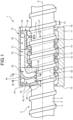
- FIG. 1 is a schematic view of a ball screw device according to an embodiment.
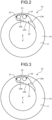
- FIG. 2 is a diagram of a nut seen from one side in an axial direction according to the embodiment.
- FIG. 3 is a diagram of the nut seen from an other side in the axial direction according to the embodiment.
- FIG. 4 is a perspective view of a screw shaft and a circulation section according to the embodiment.
- FIG. 5 is a cross-sectional view taken along line V-V in FIG. 1 .
- FIG. 6 is a cross-sectional view taken along line VI-VI in FIG. 1 .
- FIG. 7 is a diagram illustrating a relationship between the screw shaft and a tube of a ball screw according to a comparative example.
- a ball screw device 1 includes a screw shaft 2, a nut 10, a plurality of balls 3 disposed between the screw shaft 2 and the nut 10, and two circulation components 40 and 40.
- the screw shaft 2 includes an external thread 4 protruding radially outward from an outer peripheral surface and two paths that are a first inner peripheral drive surface 5 and a second inner peripheral drive surface 6 disposed between the external threads 4.
- a direction parallel to an axis X of the screw shaft 2 is referred to as an axial direction.
- the nut 10 includes a cylindrical body 11 having a cylindrical shape and penetrated by the screw shaft 2, two return paths 21 and 22 (see FIGS. 2 and 3 for return path 22), a return path partition wall 23, and housing grooves 24 and 24.
- the cylindrical body 11 includes an internal thread 12 protruding radially inward from an inner peripheral surface, and two paths that are a first outer peripheral drive surface 13 and a second outer peripheral drive surface 14 arranged between the internal threads 12.
- the second outer peripheral drive surface 14 faces the first inner peripheral drive surface 5 in a radial direction.
- a first rolling path 31 is formed between the first inner peripheral drive surface 5 and the second outer peripheral drive surface 14.
- the first outer peripheral drive surface 13 faces the second inner peripheral drive surface 6 in the radial direction.
- a second rolling path 32 is formed between the second inner peripheral drive surface 6 and the first outer peripheral drive surface 13.
- the internal thread 12 is arranged to be shifted from the external thread 4 in the axial direction by a half of one lead of the external thread 4. In other words, the external thread 4 and the internal thread 12 are alternately arranged between the rolling paths 31 and 32.
- the plurality of balls 3 is disposed on each of the first rolling path 31 and the second rolling path 32.
- a diameter of the ball 3 is slightly larger than a distance between the external thread 4 and the internal thread 12. In other words, the ball 3 is held between the external thread 4 and the internal thread 12, and a preload is applied to the ball 3. Therefore, the ball 3 comes into two-point contact with the external thread 4 and the internal thread 12, and thus a behavior of the ball 3 is stable.
- the balls 3 on the first rolling path 31 and the balls 3 on the second rolling path 32 are arranged in a back-to-back combination.
- end surfaces 15 and 16 of the cylindrical body 11 of the nut 10 have a circular outer shape.
- the end surfaces 15 and 16 of a main body are provided with a housing groove 24 recessed in the axial direction.
- the housing groove 24 is a space for housing the circulation component 40.
- a shape of the housing groove 24 seen from the axial direction corresponds to a shape of the circulation component 40 in the axial direction.
- the cylindrical body 11 has an inner side surface 24a along an inner peripheral side of the housing groove 24, a bottom surface 24b of the housing groove 24, and an outer side surface 24c along an outer peripheral side of the housing groove 24.
- the return paths 21 and 22 penetrate the cylindrical body 11 and linearly extend in the axial direction. Openings of the return paths 21 and 22 are provided in the bottom surface 24b.
- the return paths 21 and 22 are partitioned by the return path partition wall 23 that is a part of the cylindrical body 11. Diameters of the return paths 21 and 22 are slightly larger than the diameter of the ball 3. Therefore, the balls 3 smoothly roll inside the return paths 21 and 22.
- an axial length L1 of the internal thread 12 of the nut 10 is shorter than an axial length L2 of the external thread 4 of the screw shaft 2. Therefore, the nut 10 is downsized in the axial direction for a reduced axial length of the internal thread 12. As a result, a distance L3 (see FIGS. 1 and 4 ) between centers of the first rolling path 31 and the second rolling path 32 arranged between the external threads 4 is also reduced.
- the circulation component 40 is a resin component that guides the balls 3 on the rolling paths 31 and 32 to the return paths 21 and 22 of the nut 10 to circulate the balls 3.
- the circulation component 40 includes a main body 41 fitted into the housing groove 24 of the nut 10, two communication paths 42 and 43, a communication path partition wall 44, and two tongues 45 and 46 (see FIG. 1 ).
- the main body 41 of the circulation component 40 is disposed in the housing groove 24 of the nut 10.
- the main body 41 is held between the inner side surface 24a and the outer side surface 24c of the housing groove 24 (see FIGS. 2 and 3 ), and is fixed to the nut 10.
- the main body 41 has an outer peripheral surface 41a radially facing outward.
- the outer peripheral surface 41a faces the outer side surface 24c.
- the communication paths 42 and 43 are radially opened outward.
- the outer peripheral surface 41a of the main body 41 is cut out to expose the communication paths 42 and 43 from the outer peripheral surface 41a of the main body 41.
- a radially outer side of the communication paths 42 and 43 is closed by the outer side surface 24c of the nut. Therefore, the balls 3 roll along the communication paths 42 and 43.
- Diameters of the communication paths 42 and 43 are slightly larger than the diameter of the ball 3. Thus, the balls 3 smoothly roll inside the communication paths 42 and 43.
- the communication paths 42 and 43 include first communication paths 42a and 43a that extend in a radial outward direction from the rolling paths 31 and 32 and then extend in a circumferential direction, and second communication paths 42b and 43b that extend in the axial direction from the first communication paths 42a and 43a.
- the communication path partition wall 44 is a wall that partitions the communication paths 42 and 43.
- the communication path partition wall 44 includes a first communication path partition wall 44a interposed between the first communication paths 42a and 43a and a second communication path partition wall 44b interposed between the second communication paths 42b and 43b.
- a thickness L10 of the first communication path partition wall 44a is equal to the axial length L1 of the internal thread 12. Therefore, a distance L11 between centers of the first communication paths 42a and 43a is same as the distance L3 between the centers of the first rolling path 31 and the second rolling path 32.
- a thickness of the second communication path partition wall 44b is same as the thickness of the return path partition wall 23. In other words, a distance between centers of the second communication paths 42b and 43b and the distance between the centers of the return paths 21 and 22 are the same.
- the tongues 45 and 46 enter the first rolling path 31 and the second rolling path 32 to pick up the balls 3 into the communication paths 42 and 43.
- a comparative example will be described with reference to FIG. 7 .
- a ball screw device 101 including two tubes 140 and 141 as circulation components will be described.
- the tubes 140 and 141 have annular walls 140a and 141a, and insides of the walls 140a and 141a are return paths 140b and 141b, respectively.
- Ends 140c and 141c of the two tubes 140 and 141 are open toward a rolling paths 131 and 132 to pick up the balls 3 on the rolling paths 131 and 132.
- two walls 140a and 141a are interposed between the return paths 140b and 141b. Therefore, a distance L20 between centers of the return paths 140b and 141b is relatively large. As a result, a distance L21 between centers of the rolling paths 131 and 132 corresponding to the distance L20 is also increased.
- a single piece of the first communication path partition wall 44a partitions the two first communication paths 42a and 43a, and thus the distance L11 between the centers of the first communication paths 42a and 43a is small. Therefore, the distance L3 between the centers of the first rolling path 31 and the second rolling path 32 can be reduced. In other words, the axial length of the internal thread 12 can be reduced.
- the ball screw device 1 includes the screw shaft 2, the nut 10, the ball 3, and the two circulation components 40.
- the screw shaft 2 has the external thread 4 and two inner peripheral raceway surfaces (first inner peripheral drive surface 5 and second inner peripheral drive surface 6) arranged between the external threads 4.
- the nut 10 has the internal thread 12 and two outer peripheral raceway surfaces (first outer peripheral drive surface 13 and second outer peripheral drive surface 14) arranged between the internal threads 12.
- the plurality of balls 3 is arranged on each of the two rolling paths 31 and 32 between the two outer peripheral raceway surfaces and the two inner peripheral raceway surfaces.
- the circulation component 40 is provided at one end and the other end of the nut 10 to circulate the balls 3.
- the internal thread 12 and the external thread 4 hold the balls 3.
- the nut 10 has the cylindrical shape, and includes the cylindrical body 11 having the external thread 4 and the outer peripheral raceway surface (first outer peripheral drive surface 13 and second outer peripheral drive surface 14), and two return paths 21 and 22 penetrating the cylindrical body 11 in the axial direction.
- the circulation component 40 includes the main body 41 fixed to the cylindrical body 11 of the nut 10, the two communication paths 42 and 43 penetrating the main body 41 and communicating the two rolling paths 31 and 32 and the two return paths 21 and 22, the communication path partition wall 44 between the two communication paths 42 and 43 so as to partition the two communication paths 42 and 43, and two tongues 45 and 46 protruding from the main body 41 to the rolling paths 31 and 32.
- the nut 10 can be downsized in the axial direction by reducing the axial length of the internal thread 12.
- the cylindrical body 11 of the nut 10 includes two housing grooves 24 and 24 recessed from both end surfaces in the axial direction so as to house the circulation components 40, respectively.
- the circulation components 40 are disposed in the housing grooves 24, respectively.
- the circulation components 40 do not protrude from the end surfaces 15 and 16 of the nut 10. Therefore, it is possible to avoid an increase in size of the nut 10 in the axial direction.
- the ball screw device of the present disclosure is not limited to the above example.
- the thread between the first rolling path 31 and the second rolling path 32 is the internal thread 12, but it may be the external thread 4 according to the ball screw device of the present disclosure.
- an axial length of the external thread 4 is decreased.
- a distance between leads of the external thread 4 is decreased.
- the nut 10 is downsized in the axial direction.
- the balls 3 on the first rolling path 31 and the second rolling path 32 are arranged in the back-to-back combination, but the balls 3 may be arranged in a front-to-front combination.
- the thickness L10 of the first communication path partition wall 44a and the thickness of the second communication path partition wall 44b may be the same.
Landscapes
- Engineering & Computer Science (AREA)
- General Engineering & Computer Science (AREA)
- Mechanical Engineering (AREA)
- Transmission Devices (AREA)
Abstract
Description
- The present invention relates to a ball screw device.
- A ball screw device of Patent Literature 1 has two ball rolling paths. In the ball screw device of Patent Literature 1, an internal thread of a nut and an external thread of a screw shaft are alternately arranged with respect to two rolling paths. Furthermore, a distance between the internal thread and the external thread is smaller than a ball diameter. As a result, the ball is held between the internal thread and the external thread, and a preload is applied to the ball. In addition, the ball screw device of Patent Literature 1 includes two tubes as components for circulating the balls. An inside of each of the tubes is a return path where the ball passes through. Furthermore, ends of the two tubes are arranged adjacent to each other, and balls picked up from a first rolling path and balls picked from a second rolling path enter these ends.
- Patent Literature 1:
Japanese Patent Application Laid-open No. S56-147954 - In a ball screw device, a nut is required to be downsized in an axial direction. As a method of downsizing, it is conceivable to reduce a width of an internal thread or an external thread in the axial direction. When the width of the internal thread or the external thread is reduced in the axial direction, a distance between centers of a first rolling path and a second rolling path is reduced. As a result, it is also necessary to reduce a distance between centers of ends of two tubes where balls are picked up. However, when the distance between the centers of the ends of the two tubes is short, annular walls configuring the tubes may come into contact with each other. Therefore, in the ball screw device of Patent Literature 1, the distance between the centers of the two tubes cannot be reduced. Thus, in the ball screw device of Patent Literature 1, downsizing of the nut in the axial direction cannot be achieved.
- The present disclosure has been made in view of the above problem, and it is therefore an object of the present disclosure to provide a ball screw device capable of downsizing the nut in the axial direction.
- To achieve the above object, a ball screw device according to an embodiment of the present disclosure comprising: a nut including an internal thread and two outer peripheral raceway surfaces arranged between the internal threads; a screw shaft including an external thread and two inner peripheral raceway surfaces arranged between the external threads; a plurality of balls arranged on two rolling paths between the two outer peripheral raceway surfaces and the two inner peripheral raceway surfaces; and two circulation components configured to circulate the plurality of balls, one of the two circulation components being provided at one end of the nut and an other of the two circulation components being provided on an other end of the nut, wherein the internal thread and the external thread hold the plurality of balls, the nut includes: a cylindrical body having a cylindrical shape and including the external thread and the two outer peripheral raceway surfaces; and two return paths penetrating the cylindrical body in an axial direction parallel to an axis of the screw shaft, and each of the two circulation components includes: a main body fixed to the cylindrical body of the nut; two communication paths penetrating the main body and communicating the two rolling paths and the two return paths; a communication path partition wall between the two communication paths so as to partition the two communication paths; and two tongues protruding from the main body to the two rolling paths.
- A ball screw device of the present disclosure circulates balls using two return paths and two communication paths. By adjusting a thickness of a communication path partition wall, a distance between centers of the two communication paths can be reduced. Therefore, the distance between the centers of the two communication paths can be made equivalent to a distance between centers of balls in a first path and a second path. Therefore, the nut can be downsized in the axial direction by reducing the width of the internal thread or the external thread.
- As an embodiment of the ball screw device, the main body of the nut includes two housing grooves recessed from both end surfaces in the axial direction, the two housing grooves configured to house the two circulation components, and the two circulation components are respectively disposed in the two housing grooves.
- A circulation component is housed in a housing groove to downsize the nut in the axial direction.
- According to a ball screw device of the present disclosure, a nut can be downsized in an axial direction. Brief Description of Drawings
-
FIG. 1 is a schematic view of a ball screw device according to an embodiment. -
FIG. 2 is a diagram of a nut seen from one side in an axial direction according to the embodiment. -
FIG. 3 is a diagram of the nut seen from an other side in the axial direction according to the embodiment. -
FIG. 4 is a perspective view of a screw shaft and a circulation section according to the embodiment. -
FIG. 5 is a cross-sectional view taken along line V-V inFIG. 1 . -
FIG. 6 is a cross-sectional view taken along line VI-VI inFIG. 1 . -
FIG. 7 is a diagram illustrating a relationship between the screw shaft and a tube of a ball screw according to a comparative example. - Hereinafter, the present invention will be described in detail with reference to the drawings. Note that the present invention is not limited to the following mode for carrying out the present invention (hereinafter referred to as an embodiment). In addition, components in the following embodiment include those that can be easily assumed by those skilled in the art, those that are substantially the same, and those within a so-called equivalent range. Furthermore, the components disclosed in the following embodiment can be appropriately combined.
-
FIG. 1 is a schematic view of a ball screw device according to an embodiment.FIG. 2 is a diagram of a nut seen from one side in an axial direction according to the embodiment.FIG. 3 is a diagram of the nut seen from an other side in the axial direction according to the embodiment.FIG. 4 is a perspective view of a screw shaft and a circulation section according to the embodiment.FIG. 5 is a cross-sectional view taken along line V-V inFIG. 1 .FIG. 6 is a cross-sectional view taken along line VI-VI inFIG. 1 .FIG. 7 is a diagram illustrating a relationship between the screw shaft and a tube of a ball screw according to a comparative example. - As illustrated in
FIG. 1 , a ball screw device 1 includes ascrew shaft 2, anut 10, a plurality ofballs 3 disposed between thescrew shaft 2 and thenut 10, and twocirculation components screw shaft 2 includes anexternal thread 4 protruding radially outward from an outer peripheral surface and two paths that are a first innerperipheral drive surface 5 and a second innerperipheral drive surface 6 disposed between theexternal threads 4. Hereinafter, a direction parallel to an axis X of thescrew shaft 2 is referred to as an axial direction. - The
nut 10 includes acylindrical body 11 having a cylindrical shape and penetrated by thescrew shaft 2, tworeturn paths 21 and 22 (seeFIGS. 2 and 3 for return path 22), a returnpath partition wall 23, andhousing grooves cylindrical body 11 includes aninternal thread 12 protruding radially inward from an inner peripheral surface, and two paths that are a first outerperipheral drive surface 13 and a second outerperipheral drive surface 14 arranged between theinternal threads 12. - The second outer
peripheral drive surface 14 faces the first innerperipheral drive surface 5 in a radial direction. A first rollingpath 31 is formed between the first innerperipheral drive surface 5 and the second outerperipheral drive surface 14. The first outerperipheral drive surface 13 faces the second innerperipheral drive surface 6 in the radial direction. A second rollingpath 32 is formed between the second innerperipheral drive surface 6 and the first outerperipheral drive surface 13. Theinternal thread 12 is arranged to be shifted from theexternal thread 4 in the axial direction by a half of one lead of theexternal thread 4. In other words, theexternal thread 4 and theinternal thread 12 are alternately arranged between therolling paths - The plurality of
balls 3 is disposed on each of the firstrolling path 31 and the secondrolling path 32. A diameter of theball 3 is slightly larger than a distance between theexternal thread 4 and theinternal thread 12. In other words, theball 3 is held between theexternal thread 4 and theinternal thread 12, and a preload is applied to theball 3. Therefore, theball 3 comes into two-point contact with theexternal thread 4 and theinternal thread 12, and thus a behavior of theball 3 is stable. Theballs 3 on the first rollingpath 31 and theballs 3 on the second rollingpath 32 are arranged in a back-to-back combination. - As illustrated in
FIGS. 2 and 3 , end surfaces 15 and 16 of thecylindrical body 11 of thenut 10 have a circular outer shape. The end surfaces 15 and 16 of a main body are provided with ahousing groove 24 recessed in the axial direction. Thehousing groove 24 is a space for housing thecirculation component 40. As a result, thecirculation component 40 does not protrude in the axial direction from the end surfaces 15 and 16 of thecylindrical body 11, and thus an increase in a size of thenut 10 in the axial direction is avoided. A shape of thehousing groove 24 seen from the axial direction corresponds to a shape of thecirculation component 40 in the axial direction. Thecylindrical body 11 has aninner side surface 24a along an inner peripheral side of thehousing groove 24, abottom surface 24b of thehousing groove 24, and anouter side surface 24c along an outer peripheral side of thehousing groove 24. - The
return paths cylindrical body 11 and linearly extend in the axial direction. Openings of thereturn paths bottom surface 24b. Thereturn paths path partition wall 23 that is a part of thecylindrical body 11. Diameters of thereturn paths ball 3. Therefore, theballs 3 smoothly roll inside thereturn paths - In the embodiment, as illustrated in
FIG. 1 , an axial length L1 of theinternal thread 12 of thenut 10 is shorter than an axial length L2 of theexternal thread 4 of thescrew shaft 2. Therefore, thenut 10 is downsized in the axial direction for a reduced axial length of theinternal thread 12. As a result, a distance L3 (seeFIGS. 1 and4 ) between centers of the first rollingpath 31 and the second rollingpath 32 arranged between theexternal threads 4 is also reduced. - The
circulation component 40 is a resin component that guides theballs 3 on the rollingpaths return paths nut 10 to circulate theballs 3. Thecirculation component 40 includes amain body 41 fitted into thehousing groove 24 of thenut 10, twocommunication paths path partition wall 44, and twotongues 45 and 46 (seeFIG. 1 ). - As illustrated in
FIG. 1 , themain body 41 of thecirculation component 40 is disposed in thehousing groove 24 of thenut 10. Themain body 41 is held between theinner side surface 24a and theouter side surface 24c of the housing groove 24 (seeFIGS. 2 and 3 ), and is fixed to thenut 10. In addition, as illustrated inFIG. 4 , themain body 41 has an outerperipheral surface 41a radially facing outward. The outerperipheral surface 41a faces theouter side surface 24c. - As illustrated in
FIG. 4 , thecommunication paths communication paths peripheral surface 41a of themain body 41 is cut out to expose thecommunication paths peripheral surface 41a of themain body 41. A radially outer side of thecommunication paths outer side surface 24c of the nut. Therefore, theballs 3 roll along thecommunication paths communication paths ball 3. Thus, theballs 3 smoothly roll inside thecommunication paths - As illustrated in
FIGS. 5 and 6 , thecommunication paths first communication paths paths second communication paths first communication paths - As illustrated in
FIG. 4 , the communicationpath partition wall 44 is a wall that partitions thecommunication paths path partition wall 44 includes a first communicationpath partition wall 44a interposed between thefirst communication paths second communication paths - A thickness L10 of the first communication
path partition wall 44a is equal to the axial length L1 of theinternal thread 12. Therefore, a distance L11 between centers of thefirst communication paths path 31 and the second rollingpath 32. - A thickness of the second communication path partition wall 44b is same as the thickness of the return
path partition wall 23. In other words, a distance between centers of thesecond communication paths return paths - As illustrated in
FIGS. 5 and 6 , thetongues path 31 and the second rollingpath 32 to pick up theballs 3 into thecommunication paths - Next, effects of the ball screw device 1 of the present embodiment will be described. First, a comparative example will be described with reference to
FIG. 7 . In the comparative example, aball screw device 101 including twotubes FIG. 7 , thetubes annular walls walls return paths -
Ends tubes paths balls 3 on the rollingpaths walls return paths return paths paths tubes paths - On the other hand, according to the embodiment, as illustrated in
FIG. 4 , a single piece of the first communicationpath partition wall 44a partitions the twofirst communication paths first communication paths path 31 and the second rollingpath 32 can be reduced. In other words, the axial length of theinternal thread 12 can be reduced. - As described above, the ball screw device 1 according to the embodiment includes the
screw shaft 2, thenut 10, theball 3, and the twocirculation components 40. Thescrew shaft 2 has theexternal thread 4 and two inner peripheral raceway surfaces (first innerperipheral drive surface 5 and second inner peripheral drive surface 6) arranged between theexternal threads 4. Thenut 10 has theinternal thread 12 and two outer peripheral raceway surfaces (first outerperipheral drive surface 13 and second outer peripheral drive surface 14) arranged between theinternal threads 12. The plurality ofballs 3 is arranged on each of the two rollingpaths circulation component 40 is provided at one end and the other end of thenut 10 to circulate theballs 3. Theinternal thread 12 and theexternal thread 4 hold theballs 3. Thenut 10 has the cylindrical shape, and includes thecylindrical body 11 having theexternal thread 4 and the outer peripheral raceway surface (first outerperipheral drive surface 13 and second outer peripheral drive surface 14), and tworeturn paths cylindrical body 11 in the axial direction. Thecirculation component 40 includes themain body 41 fixed to thecylindrical body 11 of thenut 10, the twocommunication paths main body 41 and communicating the two rollingpaths return paths path partition wall 44 between the twocommunication paths communication paths tongues main body 41 to the rollingpaths - According to the embodiment, the
nut 10 can be downsized in the axial direction by reducing the axial length of theinternal thread 12. - In addition, the
cylindrical body 11 of thenut 10 according to the embodiment includes twohousing grooves circulation components 40, respectively. Thecirculation components 40 are disposed in thehousing grooves 24, respectively. - Accordingly, the
circulation components 40 do not protrude from the end surfaces 15 and 16 of thenut 10. Therefore, it is possible to avoid an increase in size of thenut 10 in the axial direction. - Although the embodiment has been described above, the ball screw device of the present disclosure is not limited to the above example. For example, in the embodiment, the thread between the first rolling
path 31 and the second rollingpath 32 is theinternal thread 12, but it may be theexternal thread 4 according to the ball screw device of the present disclosure. In this case, an axial length of theexternal thread 4 is decreased. As a result, a distance between leads of theexternal thread 4 is decreased. Accordingly, thenut 10 is downsized in the axial direction. Still more, in the embodiment, theballs 3 on the first rollingpath 31 and the second rollingpath 32 are arranged in the back-to-back combination, but theballs 3 may be arranged in a front-to-front combination. Furthermore, the thickness L10 of the first communicationpath partition wall 44a and the thickness of the second communication path partition wall 44b may be the same. -
- 1 BALL SCREW DEVICE
- 2 SCREW SHAFT
- 3 BALL
- 4 EXTERNAL THREAD
- 5 FIRST INNER PERIPHERAL DRIVE SURFACE
- 6 SECOND INNER PERIPHERAL DRIVE SURFACE
- 10 NUT
- 11 CYLINDRICAL BODY
- 12 INTERNAL THREAD
- 13 FIRST OUTER PERIPHERAL DRIVE SURFACE
- 14 SECOND OUTER PERIPHERAL DRIVE SURFACE
- 21, 22 RETURN PATH
- 23 RETURN PATH PARTITION WALL
- 24 HOUSING GROOVE
- 31, 32 ROLLING PATH
- 40 CIRCULATION COMPONENT
- 41 MAIN BODY
- 42, 43 COMMUNICATION PATH
- 44 COMMUNICATION PATH PARTITION WALL
- 44a FIRST COMMUNICATION PATH PARTITION WALL
- 44b SECOND COMMUNICATION PATH PARTITION WALL
- 45, 46 TONGUE
Claims (2)
- A ball screw device comprising:a nut including an internal thread and two outer peripheral raceway surfaces arranged between the internal threads;a screw shaft including an external thread and two inner peripheral raceway surfaces arranged between the external threads;a plurality of balls arranged on two rolling paths between the two outer peripheral raceway surfaces and the two inner peripheral raceway surfaces; andtwo circulation components configured to circulate the plurality of balls, one of the two circulation components being provided at one end of the nut and an other of the two circulation components being provided on an other end of the nut, whereinthe internal thread and the external thread hold the plurality of balls,the nut includes:a cylindrical body having a cylindrical shape and including the external thread and the two outer peripheral raceway surfaces; andtwo return paths penetrating the cylindrical body in an axial direction parallel to an axis of the screw shaft, andeach of the two circulation components includes:a main body fixed to the cylindrical body of the nut;two communication paths penetrating the main body and communicating the two rolling paths and the two return paths;a communication path partition wall between the two communication paths so as to partition the two communication paths; andtwo tongues protruding from the main body to the two rolling paths.
- The ball screw device according to claim 1, whereinthe cylindrical body of the nut includes two housing grooves recessed from both end surfaces in the axial direction, the two housing grooves configured to house the two circulation components, andthe two circulation components are respectively disposed in the two housing grooves.
Applications Claiming Priority (2)
| Application Number | Priority Date | Filing Date | Title |
|---|---|---|---|
| JP2021062260 | 2021-03-31 | ||
| PCT/JP2022/014786 WO2022210462A1 (en) | 2021-03-31 | 2022-03-28 | Ball screw device |
Publications (2)
| Publication Number | Publication Date |
|---|---|
| EP4317744A1 true EP4317744A1 (en) | 2024-02-07 |
| EP4317744A4 EP4317744A4 (en) | 2025-03-12 |
Family
ID=83459122
Family Applications (1)
| Application Number | Title | Priority Date | Filing Date |
|---|---|---|---|
| EP22780673.4A Pending EP4317744A4 (en) | 2021-03-31 | 2022-03-28 | BALL SCREW |
Country Status (6)
| Country | Link |
|---|---|
| US (1) | US20250020195A1 (en) |
| EP (1) | EP4317744A4 (en) |
| JP (1) | JP7827060B2 (en) |
| CN (1) | CN117157474A (en) |
| TW (1) | TWI913446B (en) |
| WO (1) | WO2022210462A1 (en) |
Family Cites Families (5)
| Publication number | Priority date | Publication date | Assignee | Title |
|---|---|---|---|---|
| JPS56120851A (en) * | 1980-02-29 | 1981-09-22 | Hiroshi Teramachi | Ball screw with retainer |
| JPS56147954A (en) | 1980-04-17 | 1981-11-17 | Hiroshi Teramachi | Retainerless ball screw |
| JP4036066B2 (en) * | 2002-09-13 | 2008-01-23 | 日本精工株式会社 | Ball circulation top and ball screw for ball screw |
| CN100398872C (en) * | 2004-08-20 | 2008-07-02 | 上银科技股份有限公司 | rolling screw |
| US8757024B2 (en) * | 2010-03-30 | 2014-06-24 | Linear Motion, Llc | Linear motion assembly with recirculation insert |
-
2022
- 2022-03-28 CN CN202280023961.7A patent/CN117157474A/en active Pending
- 2022-03-28 US US18/284,417 patent/US20250020195A1/en active Pending
- 2022-03-28 WO PCT/JP2022/014786 patent/WO2022210462A1/en not_active Ceased
- 2022-03-28 JP JP2023511219A patent/JP7827060B2/en active Active
- 2022-03-28 EP EP22780673.4A patent/EP4317744A4/en active Pending
- 2022-03-31 TW TW111112457A patent/TWI913446B/en active
Also Published As
| Publication number | Publication date |
|---|---|
| JPWO2022210462A1 (en) | 2022-10-06 |
| TWI913446B (en) | 2026-02-01 |
| EP4317744A4 (en) | 2025-03-12 |
| CN117157474A (en) | 2023-12-01 |
| WO2022210462A1 (en) | 2022-10-06 |
| US20250020195A1 (en) | 2025-01-16 |
| JP7827060B2 (en) | 2026-03-10 |
| TW202246681A (en) | 2022-12-01 |
Similar Documents
| Publication | Publication Date | Title |
|---|---|---|
| US4176888A (en) | Limited sliding ball spline assembly | |
| US8984979B2 (en) | Ball screw assembly with one-piece deflecting elements | |
| US8418573B2 (en) | Ball-screw spline | |
| US20160047452A1 (en) | Harmonic drive apparatus | |
| EP2515000B1 (en) | Ball screw assembly with recirculating cap and nut | |
| US20100043583A1 (en) | Ball screw mechanism | |
| US20200355249A1 (en) | Ball screw spline | |
| JP2015190560A (en) | ball spline | |
| US20190101196A1 (en) | Ball screw | |
| US20250020195A1 (en) | Ball screw device | |
| EP3957878A1 (en) | Nut and ball screw device | |
| US9458889B2 (en) | Reverse bearing system, apparatus, and method | |
| EP2514997A1 (en) | Ball screw assembly | |
| JP3222037U (en) | Ball spline device | |
| JP7107406B2 (en) | ball screw device | |
| EP2514998B1 (en) | Ball screw assembly with recirculating cap | |
| US8342974B2 (en) | Ball spline | |
| EP3869068B1 (en) | Ball screw device | |
| US20080110284A1 (en) | Sectional Circulating Assembly for a Ball Screw | |
| KR20180105727A (en) | Double Row Cylindrical Roller Bearings | |
| EP4317720A1 (en) | Multi-row bearing and bearing unit | |
| US12276321B2 (en) | Ball screw device | |
| CN222315689U (en) | Ball cage and rolling bearing | |
| US20260012065A1 (en) | Stepper motor | |
| EP4502423A1 (en) | Ball screw device |
Legal Events
| Date | Code | Title | Description |
|---|---|---|---|
| STAA | Information on the status of an ep patent application or granted ep patent |
Free format text: STATUS: THE INTERNATIONAL PUBLICATION HAS BEEN MADE |
|
| PUAI | Public reference made under article 153(3) epc to a published international application that has entered the european phase |
Free format text: ORIGINAL CODE: 0009012 |
|
| STAA | Information on the status of an ep patent application or granted ep patent |
Free format text: STATUS: REQUEST FOR EXAMINATION WAS MADE |
|
| 17P | Request for examination filed |
Effective date: 20230921 |
|
| AK | Designated contracting states |
Kind code of ref document: A1 Designated state(s): AL AT BE BG CH CY CZ DE DK EE ES FI FR GB GR HR HU IE IS IT LI LT LU LV MC MK MT NL NO PL PT RO RS SE SI SK SM TR |
|
| DAV | Request for validation of the european patent (deleted) | ||
| DAX | Request for extension of the european patent (deleted) | ||
| A4 | Supplementary search report drawn up and despatched |
Effective date: 20250212 |
|
| RIC1 | Information provided on ipc code assigned before grant |
Ipc: F16H 25/22 20060101AFI20250206BHEP |
|
| GRAP | Despatch of communication of intention to grant a patent |
Free format text: ORIGINAL CODE: EPIDOSNIGR1 |
|
| STAA | Information on the status of an ep patent application or granted ep patent |
Free format text: STATUS: GRANT OF PATENT IS INTENDED |
|
| INTG | Intention to grant announced |
Effective date: 20260408 |