EP4317743A1 - Ball screw - Google Patents
Ball screw Download PDFInfo
- Publication number
- EP4317743A1 EP4317743A1 EP22780644.5A EP22780644A EP4317743A1 EP 4317743 A1 EP4317743 A1 EP 4317743A1 EP 22780644 A EP22780644 A EP 22780644A EP 4317743 A1 EP4317743 A1 EP 4317743A1
- Authority
- EP
- European Patent Office
- Prior art keywords
- circulation
- ball
- screw
- notch portion
- elongated hole
- Prior art date
- Legal status (The legal status is an assumption and is not a legal conclusion. Google has not performed a legal analysis and makes no representation as to the accuracy of the status listed.)
- Pending
Links
Images



Classifications
-
- F—MECHANICAL ENGINEERING; LIGHTING; HEATING; WEAPONS; BLASTING
- F16—ENGINEERING ELEMENTS AND UNITS; GENERAL MEASURES FOR PRODUCING AND MAINTAINING EFFECTIVE FUNCTIONING OF MACHINES OR INSTALLATIONS; THERMAL INSULATION IN GENERAL
- F16H—GEARING
- F16H25/00—Gearings comprising primarily only cams, cam-followers and screw-and-nut mechanisms
- F16H25/18—Gearings comprising primarily only cams, cam-followers and screw-and-nut mechanisms for conveying or interconverting oscillating or reciprocating motions
- F16H25/20—Screw mechanisms
- F16H25/22—Screw mechanisms with balls, rollers, or similar members between the co-operating parts; Elements essential to the use of such members
- F16H25/2204—Screw mechanisms with balls, rollers, or similar members between the co-operating parts; Elements essential to the use of such members with balls
- F16H25/2214—Screw mechanisms with balls, rollers, or similar members between the co-operating parts; Elements essential to the use of such members with balls with elements for guiding the circulating balls
-
- F—MECHANICAL ENGINEERING; LIGHTING; HEATING; WEAPONS; BLASTING
- F16—ENGINEERING ELEMENTS AND UNITS; GENERAL MEASURES FOR PRODUCING AND MAINTAINING EFFECTIVE FUNCTIONING OF MACHINES OR INSTALLATIONS; THERMAL INSULATION IN GENERAL
- F16H—GEARING
- F16H25/00—Gearings comprising primarily only cams, cam-followers and screw-and-nut mechanisms
- F16H25/18—Gearings comprising primarily only cams, cam-followers and screw-and-nut mechanisms for conveying or interconverting oscillating or reciprocating motions
- F16H25/20—Screw mechanisms
- F16H25/22—Screw mechanisms with balls, rollers, or similar members between the co-operating parts; Elements essential to the use of such members
- F16H25/2204—Screw mechanisms with balls, rollers, or similar members between the co-operating parts; Elements essential to the use of such members with balls
- F16H25/2214—Screw mechanisms with balls, rollers, or similar members between the co-operating parts; Elements essential to the use of such members with balls with elements for guiding the circulating balls
- F16H25/2219—Axially mounted end-deflectors
-
- F—MECHANICAL ENGINEERING; LIGHTING; HEATING; WEAPONS; BLASTING
- F16—ENGINEERING ELEMENTS AND UNITS; GENERAL MEASURES FOR PRODUCING AND MAINTAINING EFFECTIVE FUNCTIONING OF MACHINES OR INSTALLATIONS; THERMAL INSULATION IN GENERAL
- F16H—GEARING
- F16H25/00—Gearings comprising primarily only cams, cam-followers and screw-and-nut mechanisms
- F16H25/18—Gearings comprising primarily only cams, cam-followers and screw-and-nut mechanisms for conveying or interconverting oscillating or reciprocating motions
- F16H25/20—Screw mechanisms
- F16H25/22—Screw mechanisms with balls, rollers, or similar members between the co-operating parts; Elements essential to the use of such members
- F16H25/2204—Screw mechanisms with balls, rollers, or similar members between the co-operating parts; Elements essential to the use of such members with balls
Definitions
- the present invention relates to a ball screw.
- a ball screw device of this type of the related art for example, a ball screw device shown in FIG. 7 is known.
- a nut 114 having a spiral screw groove 113 corresponding to a spiral screw groove 11 on an inner peripheral surface is screwed to a screw shaft 112 having the spiral screw groove 111 on an outer peripheral surface and extending in an axial direction.
- the screw groove 111 of the screw shaft 112 and the screw groove 113 of the nut 114 face each other to form a load raceway therebetween, and a large number of balls 115 as a rolling body are rollably loaded in the load raceway.
- a ball return passage 116 penetrating in the axial direction is formed in a wall portion of the nut 114, and notches 117 through which end portions of the ball return passage 116 open are formed in both end portions of the nut 114 (see FIG. 7 ).
- a circulation piece (circulation part) 130 for communicating the ball return passage 116 with the load raceway between the screw grooves 111, 113 is fixedly fitted into each of the notches 117.
- the circulation piece 130 is formed with a curved ball circulation groove 120 that communicates between the ball return passage 116 and the load raceway between the two screw grooves 111, 113, and a tongue portion 119 that scoops up the balls 115 which roll on the load raceway between the two screw grooves 111, 113 is provided at a front end of the ball circulation groove 120.
- a circulation passage 121 for the balls 115 is formed by each of the ball circulation grooves 120 and a ball running surface wider than a diameter of the ball provided on an inner surface of the corresponding notch 117 in a radial direction, and an endless circulation passage for the balls 115 is formed by the ball circulation passages 121, the load raceway between the two screw grooves 111, 113, and the ball return passage 116. Further, as the screw shaft 112 (or the nut 114) rotates, the nut 114 (or the screw shaft 112) moves in the axial direction via the rolling of the balls 115.
- a portion of the ball circulation groove 120 of the circulation piece 130 is formed by a ball circulation groove forming member (high-strength material) 131 made of metal having a higher strength than a strength of a synthetic resin molded body.
- the ball circulation groove forming member 131 is formed by, for example, press molding of a sheet metal or the like, and is integrally molded with the circulation piece 130.
- the inner surface of the notch 117 in the radial direction is formed to be deeper, and a plate for preventing separation such as a super hard alloy plate is mounted, and a plate surface is used as the ball running surface of the notch 117. Accordingly, when the circulating balls collide with an inner surface of a direction changing portion, the balls are prevented from being peeled off to have a bad influence on operability due to a circulation failure of the balls.
- Patent Literature 1 JP2004-340220A
- the present invention has been made in view of the problems described above, and an object of the present invention is to provide a ball screw that can ensure a more stable operation by improving a strength of a ball circulation part and can be applied to a small lead or a large lead of multi-thread specification having a small ball pitch.
- the ball screw that can ensure a more stable operation by improving a strength of a ball circulation part and can be applied to a small lead or a large lead of multi-thread specification having a small ball pitch.
- the ball screw according to the present invention is characterized by a nut and a circulation part, and a screw shaft 112 and balls 115 of the related art shown in FIG. 7 are referred to for a screw shaft and balls that are constituent elements.
- a nut 1 made of metal is formed in a cylindrical shape, and one spiral screw groove 11 is formed on an inner peripheral surface thereof.
- an outer peripheral surface of the nut 1 is formed with two notch portions 12 cut out from an outer side in a radial direction. Further, an elongated hole 7, which penetrates in the radial direction and opens corresponding to the screw groove 11 formed in the inner peripheral surface, is formed in each of the notch portions 12.
- First and second circulation components 2, 3 and a pipe 5, which serve as a circulation part, are attached to the notch portion 12, which forms a ball circulation path for circulating the balls 115 rolling between the screw grooves 111, 11 of the screw shaft 112 and the nut 1.
- two bottom wall surfaces 12a, 12b parallel to a center axis of the nut 1 and parallel to each other are formed in a stepped shape, and inner wall surfaces 12c, 12d, and 12e are formed along the radial direction on both axial sides of the two bottom wall surfaces 12a, 12b.
- the bottom wall surface 12a is formed longer on one side in the axial direction than the bottom wall surface 12b.
- a counterbore portion 12f is formed in a part of the bottom wall surface 12a adjacent to the elongated hole 7 in a longitudinal direction.
- the elongated hole 7 is formed along a lead angle ⁇ of the screw groove 11 in the longitudinal direction and has the same width as the screw groove 11.
- the elongated hole 7 is used such that a part of both longitudinal side surfaces 7a parallel to each other guides the balls 115 when the circulation part is attached to the inside of the notch portion 12 to form a scoop-up part for scooping up the balls 115 in the elongated hole 7.
- the circulation part constitutes, in the ball circulation path, a direction changing part that changes a movement direction of the scooped-up balls 115 so as to be directed in the axial direction from a direction of the scoop-up part along the lead angle ⁇ to the other circulation part, in addition to the scoop-up part described above.
- the first circulation component 2 includes a main body portion 8 forming a semi-columnar pipe accommodating groove 8a for accommodating one portion (half portion) of the pipe 5, and a tongue portion 4 accommodated in the elongated hole 7.
- the second circulation component 3 includes a main body portion 9 in which a semi-columnar pipe accommodating groove 9a for accommodating a remaining portion (half portion) of the pipe 5 is formed on a back surface of the main body portion 9 that abuts against a front surface of the first circulation component 2, and an extending portion 10 that is formed so as to be continuous with a front surface of the main body portion 9 and has a wall portion 10a constituting the scoop-up part on a back surface thereof.
- an abutting surface that abuts against the main body portion 8 of the first circulation component 2 has substantially the same size as the front surface of the main body portion, and the back surface of the extending portion 10 other than the wall portion 10a abuts against the bottom wall surface 12b of the notch portion 12.
- the pipe 5 is a curved cylindrical member forming a direction changing path of the ball circulation path, and is disposed in both pipe accommodating grooves 8a, 9a of the abutting surface where the first circulation component 2 and the second circulation component 3 abut.
- the pipe 5 is made of, for example, metal, which is a material having higher strength than materials (resin in the present embodiment) of the first and second circulation components 2, 3.
- the pipe 5 is formed in an arc shape having a single curvature, at least one end portion of the pipe 5 may be provided with a straight portion, and the pipe 5 may be exposed on both end surfaces of the circulation part.
- the pipe 5 may be formed by combining a pair of pipe pieces 5a divided into two as shown in FIGS. 6A and 6B .
- Such a pipe piece 5a may be manufactured by press working or the like.
- the first circulation component 2 is disposed in the notch portion 12 so as to abut against the bottom wall surface 12a of the notch portion 12, and the tongue portion 4 is disposed in the elongated hole 7.
- the second circulation component 3 is disposed in the notch portion 12 so as to cover the first circulation component 2. At this time, the wall portion 10a of the second circulation component 3 is accommodated in the elongated hole 7 and faces the tongue portion 4.
- the scoop-up part of the ball circulation path is constituted by the tongue portion 4 of the first circulation component 2, the wall portion 10a of the second circulation component 3, and the both longitudinal side surfaces 7a of the elongated hole 7.
- the first circulation component 2, the pipe 5, and the second circulation component 3 may be assembled into the notch portion 12 in this order, or may be assembled into the notch portion 12 in an assembled state.
- the pipe 5 is used in the direction changing part, it is possible to ensure a more stable operation by improving the strength of the ball circulation part, and since the both longitudinal side surfaces 7a of the elongated hole 7 formed in the nut 1 are used in the scoop-up part, it is also possible to apply the ball screw to a small lead or a large lead of multi-thread specification having a small ball pitch.
- the ball circulation path is configured by communicating parts of the two notch portions 12 and directly connecting the two circulation parts attached to the respective notch portions 12, but a ball return passage extending in the axial direction may be formed in the nut 1 between the two circulation parts in accordance with an axial length of the nut 1 as in FIG. 7 , for example.
- the ball screw according to the present invention is used, for example, in an XY stage used for positioning of a device that performs high-precision processing and measurement, manufacturing of a semiconductor, or the like.
- the ball screw is used in, for example, a machine tool (a machining center, a lathe, a grinder, or the like), a measuring machine (a three-dimensional measuring instrument), a semiconductor manufacturing device (a table of an exposure device, an inspection probe, or the like), or the like.
Landscapes
- Engineering & Computer Science (AREA)
- General Engineering & Computer Science (AREA)
- Mechanical Engineering (AREA)
- Transmission Devices (AREA)
Abstract
Description
- The present invention relates to a ball screw.
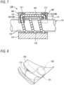
- As a ball screw device of this type of the related art, for example, a ball screw device shown in
FIG. 7 is known. - In a
ball screw device 110, anut 114 having aspiral screw groove 113 corresponding to aspiral screw groove 11 on an inner peripheral surface is screwed to ascrew shaft 112 having thespiral screw groove 111 on an outer peripheral surface and extending in an axial direction. Thescrew groove 111 of thescrew shaft 112 and thescrew groove 113 of thenut 114 face each other to form a load raceway therebetween, and a large number ofballs 115 as a rolling body are rollably loaded in the load raceway. - A
ball return passage 116 penetrating in the axial direction is formed in a wall portion of thenut 114, and notches 117 through which end portions of theball return passage 116 open are formed in both end portions of the nut 114 (seeFIG. 7 ). A circulation piece (circulation part) 130 for communicating theball return passage 116 with the load raceway between thescrew grooves notches 117. - As shown in
FIG. 8 , thecirculation piece 130 is formed with a curvedball circulation groove 120 that communicates between theball return passage 116 and the load raceway between the twoscrew grooves tongue portion 119 that scoops up theballs 115 which roll on the load raceway between the twoscrew grooves ball circulation groove 120. Acirculation passage 121 for theballs 115 is formed by each of theball circulation grooves 120 and a ball running surface wider than a diameter of the ball provided on an inner surface of thecorresponding notch 117 in a radial direction, and an endless circulation passage for theballs 115 is formed by theball circulation passages 121, the load raceway between the twoscrew grooves ball return passage 116. Further, as the screw shaft 112 (or the nut 114) rotates, the nut 114 (or the screw shaft 112) moves in the axial direction via the rolling of theballs 115. - In the ball screw described in
Patent Literature 1, a portion of theball circulation groove 120 of thecirculation piece 130 is formed by a ball circulation groove forming member (high-strength material) 131 made of metal having a higher strength than a strength of a synthetic resin molded body. The ball circulationgroove forming member 131 is formed by, for example, press molding of a sheet metal or the like, and is integrally molded with thecirculation piece 130. In addition, inPatent Literature 1, the inner surface of thenotch 117 in the radial direction is formed to be deeper, and a plate for preventing separation such as a super hard alloy plate is mounted, and a plate surface is used as the ball running surface of thenotch 117. Accordingly, when the circulating balls collide with an inner surface of a direction changing portion, the balls are prevented from being peeled off to have a bad influence on operability due to a circulation failure of the balls. - Patent Literature 1:
JP2004-340220A - However, since a circulation component described in
Patent Literature 1 is manufactured by insert molding, a structure in which two components are physically connected to each other is necessary, and the design becomes complicated. Further, there is a problem that a shape of the circulation component described inPatent Literature 1 cannot be applied to a circulation component having a small groove width of a small lead. - The present invention has been made in view of the problems described above, and an object of the present invention is to provide a ball screw that can ensure a more stable operation by improving a strength of a ball circulation part and can be applied to a small lead or a large lead of multi-thread specification having a small ball pitch.
- The above object of the present invention is achieved by the following configuration.
- (1) A ball screw including:
- a screw shaft formed with a spiral screw groove on an outer peripheral surface thereof;
- a nut formed with a spiral screw groove on an inner peripheral surface thereof and provided with a notch portion on an outer peripheral surface thereof;
- balls configured to roll between the screw groove of the screw shaft and the screw groove of the nut; and
- a circulation part forming a ball circulation path for circulating the balls rolling between both screw grooves of the screw shaft and the nut and attached to the notch portion, in which
- the nut is formed with, in the notch portion, an elongated hole that penetrates in a radial direction, and whose longitudinal direction is formed along a lead angle and parts of both longitudinal side surfaces parallel to each other guide the balls, and
- the circulation part includes
- a first circulation component that is disposed in the notch portion so as to abut against a bottom wall surface of the notch portion and has a tongue portion accommodated in the elongated hole,
- a second circulation component that is disposed in the notch portion so as to cover the first circulation component and accommodated in the elongated hole, and has a wall portion facing the tongue portion, and
- a pipe that is disposed in an abutting surface where the first circulation component and the second circulation component abut against each other, constitutes a part of the ball circulation path, and has a higher strength than materials of the first and second circulation components.
- (2) The ball screw according to (1), in which
- a scoop-up part of the ball circulation path is constituted by the tongue portion of the first circulation component, the wall portion of the second circulation component, and the both longitudinal side surfaces of the elongated hole, and
- a direction changing part of the ball circulation path is constituted by the pipe.
- In the ball screw according to the present invention, there is provided the ball screw that can ensure a more stable operation by improving a strength of a ball circulation part and can be applied to a small lead or a large lead of multi-thread specification having a small ball pitch.
-
-
FIG. 1A is a side view showing a nut of a ball screw according to an embodiment of the present invention, andFIG. 1B is a partial side view showing a notch portion of the nut from which a circulation component is removed. -
FIG. 2A is a cross-sectional view taken along a line II-II ofFIG. 1A , andFIG. 2B is a cross-sectional view taken along a line II'-II' ofFIG. 1A . -
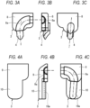
FIG. 3A is a front view of a first circulation component,FIG. 3B is a side view thereof, andFIG. 3C is a back view thereof. -
FIG. 4A is a front view of a second circulation component,FIG. 4B is a side view thereof, andFIG. 4C is a back view thereof. -
FIG. 5A is a front view of a pipe, andFIG. 5B is a side view thereof. -
FIG. 6A is a front view of a pipe according to a modification, andFIG. 6B is a side view thereof. -
FIG. 7 is a sectional view of main parts of a ball screw of the related art. -
FIG. 8 is an overall perspective view showing an example of a circulation piece used in the ball screw ofFIG. 7 . - Hereinafter, a ball screw according to an embodiment of the present invention will be described in detail with reference to the drawings. The ball screw according to the present invention is characterized by a nut and a circulation part, and a
screw shaft 112 andballs 115 of the related art shown inFIG. 7 are referred to for a screw shaft and balls that are constituent elements. - As shown in
FIG. 1A , anut 1 made of metal is formed in a cylindrical shape, and onespiral screw groove 11 is formed on an inner peripheral surface thereof. - In addition, an outer peripheral surface of the
nut 1 is formed with twonotch portions 12 cut out from an outer side in a radial direction. Further, anelongated hole 7, which penetrates in the radial direction and opens corresponding to thescrew groove 11 formed in the inner peripheral surface, is formed in each of thenotch portions 12. - First and
second circulation components pipe 5, which serve as a circulation part, are attached to thenotch portion 12, which forms a ball circulation path for circulating theballs 115 rolling between thescrew grooves screw shaft 112 and thenut 1. - As shown in
FIG. 1B , in thenotch portion 12, two bottom wall surfaces 12a, 12b parallel to a center axis of thenut 1 and parallel to each other are formed in a stepped shape, and inner wall surfaces 12c, 12d, and 12e are formed along the radial direction on both axial sides of the two bottom wall surfaces 12a, 12b. Thebottom wall surface 12a is formed longer on one side in the axial direction than the bottom wall surface 12b. Acounterbore portion 12f is formed in a part of thebottom wall surface 12a adjacent to theelongated hole 7 in a longitudinal direction. - The
elongated hole 7 is formed along a lead angle θ of thescrew groove 11 in the longitudinal direction and has the same width as thescrew groove 11. Theelongated hole 7 is used such that a part of both longitudinal side surfaces 7a parallel to each other guides theballs 115 when the circulation part is attached to the inside of thenotch portion 12 to form a scoop-up part for scooping up theballs 115 in theelongated hole 7. - The circulation part constitutes, in the ball circulation path, a direction changing part that changes a movement direction of the scooped-up
balls 115 so as to be directed in the axial direction from a direction of the scoop-up part along the lead angle θ to the other circulation part, in addition to the scoop-up part described above. - Specifically, as shown in
FIGS. 3A to 3C , thefirst circulation component 2 includes amain body portion 8 forming a semi-columnarpipe accommodating groove 8a for accommodating one portion (half portion) of thepipe 5, and atongue portion 4 accommodated in theelongated hole 7. - As shown in
FIGS. 4A to 4C , thesecond circulation component 3 includes amain body portion 9 in which a semi-columnarpipe accommodating groove 9a for accommodating a remaining portion (half portion) of thepipe 5 is formed on a back surface of themain body portion 9 that abuts against a front surface of thefirst circulation component 2, and an extendingportion 10 that is formed so as to be continuous with a front surface of themain body portion 9 and has awall portion 10a constituting the scoop-up part on a back surface thereof. In themain body portion 9, an abutting surface that abuts against themain body portion 8 of thefirst circulation component 2 has substantially the same size as the front surface of the main body portion, and the back surface of the extendingportion 10 other than thewall portion 10a abuts against the bottom wall surface 12b of thenotch portion 12. - As shown in
FIGS. 5A and 5B , thepipe 5 is a curved cylindrical member forming a direction changing path of the ball circulation path, and is disposed in bothpipe accommodating grooves first circulation component 2 and thesecond circulation component 3 abut. Thepipe 5 is made of, for example, metal, which is a material having higher strength than materials (resin in the present embodiment) of the first andsecond circulation components - Although the
pipe 5 is formed in an arc shape having a single curvature, at least one end portion of thepipe 5 may be provided with a straight portion, and thepipe 5 may be exposed on both end surfaces of the circulation part. - The
pipe 5 may be formed by combining a pair ofpipe pieces 5a divided into two as shown inFIGS. 6A and 6B . Such apipe piece 5a may be manufactured by press working or the like. - The
first circulation component 2 is disposed in thenotch portion 12 so as to abut against thebottom wall surface 12a of thenotch portion 12, and thetongue portion 4 is disposed in theelongated hole 7. In addition, thesecond circulation component 3 is disposed in thenotch portion 12 so as to cover thefirst circulation component 2. At this time, thewall portion 10a of thesecond circulation component 3 is accommodated in theelongated hole 7 and faces thetongue portion 4. - Accordingly, the scoop-up part of the ball circulation path is constituted by the
tongue portion 4 of thefirst circulation component 2, thewall portion 10a of thesecond circulation component 3, and the both longitudinal side surfaces 7a of theelongated hole 7. - The
first circulation component 2, thepipe 5, and thesecond circulation component 3 may be assembled into thenotch portion 12 in this order, or may be assembled into thenotch portion 12 in an assembled state. - According to the ball screw of the present embodiment, since the
pipe 5 is used in the direction changing part, it is possible to ensure a more stable operation by improving the strength of the ball circulation part, and since the both longitudinal side surfaces 7a of theelongated hole 7 formed in thenut 1 are used in the scoop-up part, it is also possible to apply the ball screw to a small lead or a large lead of multi-thread specification having a small ball pitch. - The present invention is not limited to the embodiment and the modifications described above, and modifications, improvements, and the like can be appropriately made.
- In the present embodiment, the ball circulation path is configured by communicating parts of the two
notch portions 12 and directly connecting the two circulation parts attached to therespective notch portions 12, but a ball return passage extending in the axial direction may be formed in thenut 1 between the two circulation parts in accordance with an axial length of thenut 1 as inFIG. 7 , for example. - The ball screw according to the present invention is used, for example, in an XY stage used for positioning of a device that performs high-precision processing and measurement, manufacturing of a semiconductor, or the like. In addition, the ball screw is used in, for example, a machine tool (a machining center, a lathe, a grinder, or the like), a measuring machine (a three-dimensional measuring instrument), a semiconductor manufacturing device (a table of an exposure device, an inspection probe, or the like), or the like.
- The present application is based on a Japanese patent application (
Japanese Patent Application No. 2021-062356) filed on March 31, 2021 -
- 1 nut
- 2 first circulation component
- 3 second circulation component
- 4 tongue portion
- 5 pipe
- 7 elongated hole
- 8, 9 main body portion
- 10a wall portion
- 11 screw groove
- 12 notch portion
- 111 screw groove
- 112 screw shaft
- 115 ball
Claims (2)
- A ball screw comprising:a screw shaft formed with a spiral screw groove on an outer peripheral surface thereof;a nut formed with a spiral screw groove on an inner peripheral surface thereof and provided with a notch portion on an outer peripheral surface thereof;balls configured to roll between the screw groove of the screw shaft and the screw groove of the nut; anda circulation part forming a ball circulation path for circulating the balls rolling between both screw grooves of the screw shaft and the nut and attached to the notch portion,wherein the nut is formed with, in the notch portion, an elongated hole that penetrates in a radial direction, and whose longitudinal direction is formed along a lead angle and parts of both longitudinal side surfaces parallel to each other guide the balls, andwherein the circulation part includesa first circulation component that is disposed in the notch portion so as to abut against a bottom wall surface of the notch portion and has a tongue portion accommodated in the elongated hole,a second circulation component that is disposed in the notch portion so as to cover the first circulation component and accommodated in the elongated hole, and has a wall portion facing the tongue portion, anda pipe that is disposed in an abutting surface where the first circulation component and the second circulation component abut against each other, constitutes a part of the ball circulation path, and has a higher strength than materials of the first and second circulation components.
- The ball screw according to claim 1,wherein a scoop-up part of the ball circulation path is constituted by the tongue portion of the first circulation component, the wall portion of the second circulation component, and the both longitudinal side surfaces of the elongated hole, andwherein a direction changing part of the ball circulation path is constituted by the pipe.
Applications Claiming Priority (2)
| Application Number | Priority Date | Filing Date | Title |
|---|---|---|---|
| JP2021062356A JP7487699B2 (en) | 2021-03-31 | 2021-03-31 | Ball screw |
| PCT/JP2022/014700 WO2022210432A1 (en) | 2021-03-31 | 2022-03-25 | Ball screw |
Publications (2)
| Publication Number | Publication Date |
|---|---|
| EP4317743A1 true EP4317743A1 (en) | 2024-02-07 |
| EP4317743A4 EP4317743A4 (en) | 2024-08-28 |
Family
ID=83456239
Family Applications (1)
| Application Number | Title | Priority Date | Filing Date |
|---|---|---|---|
| EP22780644.5A Pending EP4317743A4 (en) | 2021-03-31 | 2022-03-25 | BALL SCREW |
Country Status (6)
| Country | Link |
|---|---|
| US (1) | US12305737B2 (en) |
| EP (1) | EP4317743A4 (en) |
| JP (1) | JP7487699B2 (en) |
| CN (1) | CN117120750A (en) |
| TW (1) | TWI885252B (en) |
| WO (1) | WO2022210432A1 (en) |
Family Cites Families (11)
| Publication number | Priority date | Publication date | Assignee | Title |
|---|---|---|---|---|
| JP2591913Y2 (en) * | 1991-12-13 | 1999-03-10 | 日本精工株式会社 | Ball screw device |
| JP2004108454A (en) * | 2002-09-17 | 2004-04-08 | Nsk Ltd | Tube guide for ball screw, ball screw, and method of manufacturing ball screw |
| JP2004340220A (en) * | 2003-05-14 | 2004-12-02 | Nsk Ltd | Ball screw device |
| JP2006002812A (en) * | 2004-06-16 | 2006-01-05 | Nsk Ltd | Ball screw |
| DE102006012185B4 (en) * | 2006-03-16 | 2012-03-01 | Hiwin Technologies Corp. | Ball screw drive |
| JP4482552B2 (en) | 2006-12-15 | 2010-06-16 | 上銀科技股▲分▼有限公司 | Ball screw reflux structure and reflux element thereof |
| JP2010038196A (en) * | 2008-07-31 | 2010-02-18 | Thk Co Ltd | Screw device |
| JP4869360B2 (en) | 2009-01-16 | 2012-02-08 | 上銀科技股▲分▼有限公司 | Ball screw with external reflux parts |
| JP3165152U (en) * | 2010-10-19 | 2011-01-06 | 上銀科技股▲分▼有限公司 | External circulation ball screw |
| JP6151161B2 (en) | 2013-11-29 | 2017-06-21 | 株式会社ショーワ | Ball screw and power steering device |
| CN110653242A (en) | 2019-10-11 | 2020-01-07 | 台州市椒江蒙特智能装备有限公司 | Fiber material rapid degradation equipment |
-
2021
- 2021-03-31 JP JP2021062356A patent/JP7487699B2/en active Active
-
2022
- 2022-03-25 US US18/284,986 patent/US12305737B2/en active Active
- 2022-03-25 EP EP22780644.5A patent/EP4317743A4/en active Pending
- 2022-03-25 CN CN202280026395.5A patent/CN117120750A/en active Pending
- 2022-03-25 WO PCT/JP2022/014700 patent/WO2022210432A1/en not_active Ceased
- 2022-03-31 TW TW111112501A patent/TWI885252B/en active
Also Published As
| Publication number | Publication date |
|---|---|
| EP4317743A4 (en) | 2024-08-28 |
| US12305737B2 (en) | 2025-05-20 |
| JP2022157879A (en) | 2022-10-14 |
| CN117120750A (en) | 2023-11-24 |
| JP7487699B2 (en) | 2024-05-21 |
| US20240183434A1 (en) | 2024-06-06 |
| TW202242279A (en) | 2022-11-01 |
| TWI885252B (en) | 2025-06-01 |
| WO2022210432A1 (en) | 2022-10-06 |
Similar Documents
| Publication | Publication Date | Title |
|---|---|---|
| US20100242651A1 (en) | Rolling-element screw device | |
| JP6334986B2 (en) | Ball spline | |
| US10914365B2 (en) | Ball screw spline | |
| US12305737B2 (en) | Ball screw | |
| JPS6249501B2 (en) | ||
| CN116006646B (en) | ball screw | |
| TW201814186A (en) | Circulation component retainer and ball screw | |
| JP2009024843A (en) | Ball screw device | |
| JP7107406B2 (en) | ball screw device | |
| JP2007255435A (en) | Rolling element screw device and manufacturing method for rolling element screw device | |
| JP2025089774A (en) | Ball screw | |
| JP2024004963A (en) | Circulation piece for ball screw and ball screw | |
| WO2009084164A1 (en) | Ball screw device | |
| JP5138463B2 (en) | Ball screw device | |
| US11680628B2 (en) | Ball screw device | |
| JP3150527U (en) | Rolling element screw device | |
| EP4317742A1 (en) | Multi-row ball screw | |
| JP6383553B2 (en) | Ball spline | |
| WO2011048892A1 (en) | Motion guiding device | |
| JP3249327U (en) | Combined circulator and ball screw using combined circulator | |
| Kulkarni et al. | Recirculating ball screw | |
| JP2023167944A (en) | ball screw device | |
| JP2024017175A (en) | Grinding method of ball screw nut and ball screw | |
| JP2007155036A (en) | Linear bushing and manufacturing method thereof | |
| JP2003194177A (en) | Ball screw |
Legal Events
| Date | Code | Title | Description |
|---|---|---|---|
| STAA | Information on the status of an ep patent application or granted ep patent |
Free format text: STATUS: THE INTERNATIONAL PUBLICATION HAS BEEN MADE |
|
| PUAI | Public reference made under article 153(3) epc to a published international application that has entered the european phase |
Free format text: ORIGINAL CODE: 0009012 |
|
| STAA | Information on the status of an ep patent application or granted ep patent |
Free format text: STATUS: REQUEST FOR EXAMINATION WAS MADE |
|
| 17P | Request for examination filed |
Effective date: 20230929 |
|
| AK | Designated contracting states |
Kind code of ref document: A1 Designated state(s): AL AT BE BG CH CY CZ DE DK EE ES FI FR GB GR HR HU IE IS IT LI LT LU LV MC MK MT NL NO PL PT RO RS SE SI SK SM TR |
|
| DAV | Request for validation of the european patent (deleted) | ||
| DAX | Request for extension of the european patent (deleted) | ||
| A4 | Supplementary search report drawn up and despatched |
Effective date: 20240730 |
|
| RIC1 | Information provided on ipc code assigned before grant |
Ipc: F16H 25/24 20060101ALI20240725BHEP Ipc: F16H 25/22 20060101AFI20240725BHEP |
|
| STAA | Information on the status of an ep patent application or granted ep patent |
Free format text: STATUS: EXAMINATION IS IN PROGRESS |
|
| 17Q | First examination report despatched |
Effective date: 20251118 |