EP4317710A2 - Pneumatic cylinder - Google Patents
Pneumatic cylinder Download PDFInfo
- Publication number
- EP4317710A2 EP4317710A2 EP23188863.7A EP23188863A EP4317710A2 EP 4317710 A2 EP4317710 A2 EP 4317710A2 EP 23188863 A EP23188863 A EP 23188863A EP 4317710 A2 EP4317710 A2 EP 4317710A2
- Authority
- EP
- European Patent Office
- Prior art keywords
- tube
- jacket
- pneumatic cylinder
- rod
- carbon fibre
- Prior art date
- Legal status (The legal status is an assumption and is not a legal conclusion. Google has not performed a legal analysis and makes no representation as to the accuracy of the status listed.)
- Pending
Links
Images



Classifications
-
- F—MECHANICAL ENGINEERING; LIGHTING; HEATING; WEAPONS; BLASTING
- F15—FLUID-PRESSURE ACTUATORS; HYDRAULICS OR PNEUMATICS IN GENERAL
- F15B—SYSTEMS ACTING BY MEANS OF FLUIDS IN GENERAL; FLUID-PRESSURE ACTUATORS, e.g. SERVOMOTORS; DETAILS OF FLUID-PRESSURE SYSTEMS, NOT OTHERWISE PROVIDED FOR
- F15B15/00—Fluid-actuated devices for displacing a member from one position to another; Gearing associated therewith
- F15B15/08—Characterised by the construction of the motor unit
- F15B15/14—Characterised by the construction of the motor unit of the straight-cylinder type
- F15B15/1423—Component parts; Constructional details
- F15B15/1428—Cylinders
-
- F—MECHANICAL ENGINEERING; LIGHTING; HEATING; WEAPONS; BLASTING
- F15—FLUID-PRESSURE ACTUATORS; HYDRAULICS OR PNEUMATICS IN GENERAL
- F15B—SYSTEMS ACTING BY MEANS OF FLUIDS IN GENERAL; FLUID-PRESSURE ACTUATORS, e.g. SERVOMOTORS; DETAILS OF FLUID-PRESSURE SYSTEMS, NOT OTHERWISE PROVIDED FOR
- F15B15/00—Fluid-actuated devices for displacing a member from one position to another; Gearing associated therewith
- F15B15/08—Characterised by the construction of the motor unit
- F15B15/10—Characterised by the construction of the motor unit the motor being of diaphragm type
-
- F—MECHANICAL ENGINEERING; LIGHTING; HEATING; WEAPONS; BLASTING
- F15—FLUID-PRESSURE ACTUATORS; HYDRAULICS OR PNEUMATICS IN GENERAL
- F15B—SYSTEMS ACTING BY MEANS OF FLUIDS IN GENERAL; FLUID-PRESSURE ACTUATORS, e.g. SERVOMOTORS; DETAILS OF FLUID-PRESSURE SYSTEMS, NOT OTHERWISE PROVIDED FOR
- F15B15/00—Fluid-actuated devices for displacing a member from one position to another; Gearing associated therewith
- F15B15/08—Characterised by the construction of the motor unit
- F15B15/14—Characterised by the construction of the motor unit of the straight-cylinder type
- F15B15/1423—Component parts; Constructional details
-
- F—MECHANICAL ENGINEERING; LIGHTING; HEATING; WEAPONS; BLASTING
- F15—FLUID-PRESSURE ACTUATORS; HYDRAULICS OR PNEUMATICS IN GENERAL
- F15B—SYSTEMS ACTING BY MEANS OF FLUIDS IN GENERAL; FLUID-PRESSURE ACTUATORS, e.g. SERVOMOTORS; DETAILS OF FLUID-PRESSURE SYSTEMS, NOT OTHERWISE PROVIDED FOR
- F15B15/00—Fluid-actuated devices for displacing a member from one position to another; Gearing associated therewith
- F15B15/08—Characterised by the construction of the motor unit
- F15B15/14—Characterised by the construction of the motor unit of the straight-cylinder type
- F15B15/1423—Component parts; Constructional details
- F15B15/1447—Pistons; Piston to piston rod assemblies
-
- F—MECHANICAL ENGINEERING; LIGHTING; HEATING; WEAPONS; BLASTING
- F15—FLUID-PRESSURE ACTUATORS; HYDRAULICS OR PNEUMATICS IN GENERAL
- F15B—SYSTEMS ACTING BY MEANS OF FLUIDS IN GENERAL; FLUID-PRESSURE ACTUATORS, e.g. SERVOMOTORS; DETAILS OF FLUID-PRESSURE SYSTEMS, NOT OTHERWISE PROVIDED FOR
- F15B15/00—Fluid-actuated devices for displacing a member from one position to another; Gearing associated therewith
- F15B15/08—Characterised by the construction of the motor unit
- F15B15/14—Characterised by the construction of the motor unit of the straight-cylinder type
- F15B15/1423—Component parts; Constructional details
- F15B15/1457—Piston rods
-
- F—MECHANICAL ENGINEERING; LIGHTING; HEATING; WEAPONS; BLASTING
- F15—FLUID-PRESSURE ACTUATORS; HYDRAULICS OR PNEUMATICS IN GENERAL
- F15B—SYSTEMS ACTING BY MEANS OF FLUIDS IN GENERAL; FLUID-PRESSURE ACTUATORS, e.g. SERVOMOTORS; DETAILS OF FLUID-PRESSURE SYSTEMS, NOT OTHERWISE PROVIDED FOR
- F15B15/00—Fluid-actuated devices for displacing a member from one position to another; Gearing associated therewith
- F15B15/08—Characterised by the construction of the motor unit
- F15B15/14—Characterised by the construction of the motor unit of the straight-cylinder type
- F15B15/1423—Component parts; Constructional details
- F15B15/1476—Special return means
-
- F—MECHANICAL ENGINEERING; LIGHTING; HEATING; WEAPONS; BLASTING
- F15—FLUID-PRESSURE ACTUATORS; HYDRAULICS OR PNEUMATICS IN GENERAL
- F15B—SYSTEMS ACTING BY MEANS OF FLUIDS IN GENERAL; FLUID-PRESSURE ACTUATORS, e.g. SERVOMOTORS; DETAILS OF FLUID-PRESSURE SYSTEMS, NOT OTHERWISE PROVIDED FOR
- F15B15/00—Fluid-actuated devices for displacing a member from one position to another; Gearing associated therewith
- F15B15/20—Other details, e.g. assembly with regulating devices
- F15B15/22—Other details, e.g. assembly with regulating devices for accelerating or decelerating the stroke
- F15B15/223—Other details, e.g. assembly with regulating devices for accelerating or decelerating the stroke having a piston with a piston extension or piston recess which completely seals the main fluid outlet as the piston approaches its end position
-
- F—MECHANICAL ENGINEERING; LIGHTING; HEATING; WEAPONS; BLASTING
- F15—FLUID-PRESSURE ACTUATORS; HYDRAULICS OR PNEUMATICS IN GENERAL
- F15B—SYSTEMS ACTING BY MEANS OF FLUIDS IN GENERAL; FLUID-PRESSURE ACTUATORS, e.g. SERVOMOTORS; DETAILS OF FLUID-PRESSURE SYSTEMS, NOT OTHERWISE PROVIDED FOR
- F15B2211/00—Circuits for servomotor systems
- F15B2211/70—Output members, e.g. hydraulic motors or cylinders or control therefor
- F15B2211/705—Output members, e.g. hydraulic motors or cylinders or control therefor characterised by the type of output members or actuators
- F15B2211/7051—Linear output members
- F15B2211/7052—Single-acting output members
-
- F—MECHANICAL ENGINEERING; LIGHTING; HEATING; WEAPONS; BLASTING
- F15—FLUID-PRESSURE ACTUATORS; HYDRAULICS OR PNEUMATICS IN GENERAL
- F15B—SYSTEMS ACTING BY MEANS OF FLUIDS IN GENERAL; FLUID-PRESSURE ACTUATORS, e.g. SERVOMOTORS; DETAILS OF FLUID-PRESSURE SYSTEMS, NOT OTHERWISE PROVIDED FOR
- F15B2211/00—Circuits for servomotor systems
- F15B2211/70—Output members, e.g. hydraulic motors or cylinders or control therefor
- F15B2211/705—Output members, e.g. hydraulic motors or cylinders or control therefor characterised by the type of output members or actuators
- F15B2211/7051—Linear output members
- F15B2211/7053—Double-acting output members
-
- F—MECHANICAL ENGINEERING; LIGHTING; HEATING; WEAPONS; BLASTING
- F15—FLUID-PRESSURE ACTUATORS; HYDRAULICS OR PNEUMATICS IN GENERAL
- F15B—SYSTEMS ACTING BY MEANS OF FLUIDS IN GENERAL; FLUID-PRESSURE ACTUATORS, e.g. SERVOMOTORS; DETAILS OF FLUID-PRESSURE SYSTEMS, NOT OTHERWISE PROVIDED FOR
- F15B2211/00—Circuits for servomotor systems
- F15B2211/80—Other types of control related to particular problems or conditions
- F15B2211/885—Control specific to the type of fluid, e.g. specific to magnetorheological fluid
- F15B2211/8855—Compressible fluids, e.g. specific to pneumatics
-
- F—MECHANICAL ENGINEERING; LIGHTING; HEATING; WEAPONS; BLASTING
- F15—FLUID-PRESSURE ACTUATORS; HYDRAULICS OR PNEUMATICS IN GENERAL
- F15B—SYSTEMS ACTING BY MEANS OF FLUIDS IN GENERAL; FLUID-PRESSURE ACTUATORS, e.g. SERVOMOTORS; DETAILS OF FLUID-PRESSURE SYSTEMS, NOT OTHERWISE PROVIDED FOR
- F15B2215/00—Fluid-actuated devices for displacing a member from one position to another
- F15B2215/30—Constructional details thereof
- F15B2215/305—Constructional details thereof characterised by the use of special materials
Definitions
- the present invention concerns a pneumatic cylinder, according to claim 1.
- the present invention also concerns a process for making a pneumatic cylinder according to the invention.
- the fundamental components of a pneumatic cylinder are always: a jacket closed at its ends by two heads, a rod that enters the jacket through an opening in one of the two heads and which is connected to a piston capable of sliding in the cylinder.
- the cylinder touches the inner walls of the jacket dividing the volume into two chambers: a front chamber and a rear chamber.
- the general scheme is always based on the principle that by injecting compressed air or any fluid, for example into the front chamber through the feeding conduit, the piston will be subjected to a pressure and therefore to a force that will make it move inside the jacket reducing the volume of the rear chamber.
- cylinders have numerous applications, including also anthropomorphic robots where they are used to move the different sections that make up the robotic arm.
- This equipment is widely used in technologically advanced industrial areas, but they cannot lift excessively high loads due to their construction characteristics.
- the maximum liftable weight is around 150 kg.
- the rod must also be sturdy enough to transmit the motion from or to the piston.
- the main purpose of the present invention is to build a pneumatic cylinder having characteristics that can compare to the traditional metal ones, but which is lighter so that it can be installed on machines where speed, very low inertia, precision, lightness, resistance to aggressive environments and radiotransparency are required.
- a further object of the present invention is to provide a pneumatic cylinder which, in addition to lightness, offers increased ease in adjusting the end-of-stroke damping force.
- the term "carbon fibre” will often be used in the present description and claims. However, it is specified that the term “carbon” may also be used in an equivalent way.
- the pneumatic cylinder illustrated in Figs. 1-3 comprises a jacket 2 consisting of a carbon fibre tube covered internally by a metal layer, two heads 3 which close the ends of said jacket 2 and a piston 4 adapted to slide inside the jacket. It can be noted that, with respect to DE 102004008523 A1 , the jacket 2 of a pneumatic cylinder referred to in the invention does not have any metal layer on its outer surface, so as to reduce the overall weight.
- the rod 5 which is connected to the piston 4 has a carbon fibre core 6 covered on the outside by a metal layer 7. Again, with respect to DE 102004008523 A1 , it is noted that the rod 5 does not have its own carbon fibre core 6 enclosed between two metal layers, again for weight reasons.
- the realization of the device according to the invention is simpler than a device made according to the teachings of DE 102004008523 , precisely due to the use of a metal sandwich in the latter.
- a pneumatic cylinder referred to in the invention it is advisable to follow the steps that will be described below which are not disclosed in DE 102004008523 .
- a device according to the invention is lighter and stronger than the device disclosed in DE 102004008523 ; less metal is used, and carbon fibre is more resistant than the plastic material reinforced with carbon described in DE 102004008523 .
- a simple rod entirely made of carbon fibre would not be suitable for use inside the pneumatic cylinder, since, as mentioned above, the characteristics of carbon do not match with the internal environment of the cylinder in which lubricating fluids are present that would penetrate into it due to its porosity.
- there are seals that serve to create a watertight seal between the inside of the cylinder and the external environment and the roughness of the carbon would ruin them very quickly.
- the rod 5 can be internally hollow.
- the metal layer 7 of the rod 5 is placed on the carbon fibre core 6 by electroplating, bonding or painting.
- the rod can also be obtained starting from a carbon fibre solid or hollow tube that can be covered for example:
- Figs. 4 to 7 illustrate a particular solution to facilitate the adjustment of the end-of-stroke dampening in which a head 3 has a cavity 30 that puts the inside of the jacket 2 in fluid communication with the external environment and inside which a peg 8 is slidably housed.
- the seats 10 identify a series of steps which, based on their distance with respect to the cavity 30, allow the degree of penetration of the peg 8 into said cavity to be varied.
- the cavity 30 can coincide with the aforementioned pressurised fluid feeding conduit.
Landscapes
- Engineering & Computer Science (AREA)
- Physics & Mathematics (AREA)
- Fluid Mechanics (AREA)
- Mechanical Engineering (AREA)
- General Engineering & Computer Science (AREA)
- Actuator (AREA)
Abstract
Description
- The present invention concerns a pneumatic cylinder, according to
claim 1. The present invention also concerns a process for making a pneumatic cylinder according to the invention. - In general, there are many types of pneumatic cylinders of the single-acting, double-acting, spring-loaded type and with so many other functional combinations.
- The fundamental components of a pneumatic cylinder are always: a jacket closed at its ends by two heads, a rod that enters the jacket through an opening in one of the two heads and which is connected to a piston capable of sliding in the cylinder. Generally, the cylinder touches the inner walls of the jacket dividing the volume into two chambers: a front chamber and a rear chamber.
- The general scheme is always based on the principle that by injecting compressed air or any fluid, for example into the front chamber through the feeding conduit, the piston will be subjected to a pressure and therefore to a force that will make it move inside the jacket reducing the volume of the rear chamber.
- On the contrary, by injecting air into the rear chamber, the piston will tend to move inside the jacket, reducing the volume of the front chamber.
- Since the piston is connected to the rod, if the jacket of the cylinder is anchored to a support element such as the frame, parts can be set in motion through the rod, alternating the motion of the rod depending on which chamber is under pressure. Appropriate valves control the entry and the exit of the air from the chambers.
- These cylinders have numerous applications, including also anthropomorphic robots where they are used to move the different sections that make up the robotic arm.
- This equipment is widely used in technologically advanced industrial areas, but they cannot lift excessively high loads due to their construction characteristics. For medium-sized robots, the maximum liftable weight is around 150 kg.
- It is evident that the lighter the components of the robot are, the more it will be able to lift heavier weights since it will waste less force to lift itself.
- The classic pneumatic cylinders are made of metal, but it would be preferable to make them of lighter materials. Unfortunately, the need to obtain a light cylinder clashes with the characteristics of roughness that the material of which it is composed must present to allow the correct sliding between piston and jacket.
- In addition, the rod must also be sturdy enough to transmit the motion from or to the piston.
- An extremely light material is carbon, but if a pneumatic cylinder were made entirely of carbon, the correct sliding between piston and jacket would not be obtained. Furthermore, the porosity of carbon does not match well with the lubricating fluids used inside the cylinder.
- The most important document of the state of the art is the German publication
DE 102004008523 A1 , in which there is described (the references in brackets concern this document) a pneumatic cylinder, comprising a metal jacket having an outer surface and an inner surface, between which, sandwiched, there is a layer of carbon fibre-reinforced plastic material, two heads (11, 13) which close the ends of said metal jacket and a piston (53) adapted to slide inside the jacket, wherein said cylinder also comprises a rod (50) connected to the piston (53) having a carbon fibre-reinforced plastic core (61) sandwiched between two metal layers (57, 59). The characteristics of lightness of this cylinder are not optimal due to the excessive use of heavy metal material. - Another document of the state of the art is
US 7185581 B2 . - The main purpose of the present invention is to build a pneumatic cylinder having characteristics that can compare to the traditional metal ones, but which is lighter so that it can be installed on machines where speed, very low inertia, precision, lightness, resistance to aggressive environments and radiotransparency are required.
- The considerable reduction in the weight of the pneumatic cylinders referred to in the invention entails a corresponding increase in the maximum weight that can be lifted with the same size of the robot and this over time translates into:
- a very high increase in production;
- significant energy savings;
- a significant reduction in wear of the moving parts;
- Countless other applications are possible for a product of this type: from automotive, to marine, to aeronautical, to medical.
- A further object of the present invention is to provide a pneumatic cylinder which, in addition to lightness, offers increased ease in adjusting the end-of-stroke damping force.
- At present, there are countless types of cylinders on the market, all with the adjustment of the end-of-stroke damping through the adjustment of a screw placed in an exhaust, which by rotating modifies the flow of compressed air from the piston near the end-of-stroke (in both directions); the more air passes towards the exhaust and the less the piston is damped at the end-of stroke, the less air passes, the more the latter is compressed towards the outlet vent and the more the piston is damped.
- The present invention will now be illustrated and described in detail, with reference to a particular embodiment thereof, made by way of non-limiting example, with the aid of the attached drawing tables, where:
-
Fig. 1 shows a side view of a pneumatic cylinder referred to in the invention; -
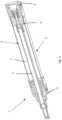
Fig. 2 shows a section of a pneumatic cylinder referred to in the invention; -
Fig. 3 shows a perspective sectional view of a pneumatic cylinder referred to in the invention; -
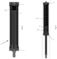
Figs. 4A-B shows a sectional detail of an embodiment of a pneumatic cylinder referred to in the invention; -
Fig. 5 shows a sectional view of a ring nut present in the embodiment ofFigs. 4A-B ; -
Figs. 6A-D show different steps of adjustment of a peg for the control of the end-of-stroke damping force; -
Figs. 7A-D show the steps ofFigs. 6A-D seen from above. - The term "carbon fibre" will often be used in the present description and claims. However, it is specified that the term "carbon" may also be used in an equivalent way. The pneumatic cylinder illustrated in
Figs. 1-3 comprises ajacket 2 consisting of a carbon fibre tube covered internally by a metal layer, twoheads 3 which close the ends of saidjacket 2 and apiston 4 adapted to slide inside the jacket. It can be noted that, with respect toDE 102004008523 A1 , thejacket 2 of a pneumatic cylinder referred to in the invention does not have any metal layer on its outer surface, so as to reduce the overall weight. - The
rod 5 which is connected to thepiston 4 has acarbon fibre core 6 covered on the outside by ametal layer 7. Again, with respect toDE 102004008523 A1 , it is noted that therod 5 does not have its owncarbon fibre core 6 enclosed between two metal layers, again for weight reasons. - Document
DE 102004008523 A1 also always describes the fact that carbon is used to strengthen a plastic material. Carbon fibre without any plastic material is used in the invention as referred to in the invention. - The realization of the device according to the invention is simpler than a device made according to the teachings of
DE 102004008523 , precisely due to the use of a metal sandwich in the latter. For the realization of a pneumatic cylinder referred to in the invention, it is advisable to follow the steps that will be described below which are not disclosed inDE 102004008523 . A device according to the invention is lighter and stronger than the device disclosed inDE 102004008523 ; less metal is used, and carbon fibre is more resistant than the plastic material reinforced with carbon described inDE 102004008523 . - A simple rod entirely made of carbon fibre would not be suitable for use inside the pneumatic cylinder, since, as mentioned above, the characteristics of carbon do not match with the internal environment of the cylinder in which lubricating fluids are present that would penetrate into it due to its porosity. In addition, at the openings on the heads through which the rod enters the cylinder, there are seals that serve to create a watertight seal between the inside of the cylinder and the external environment and the roughness of the carbon would ruin them very quickly.
- For this reason it is necessary to cover the
carbon fibre core 6 with ametal layer 7. To increase the lightness of thepneumatic cylinder 1, therod 5 can be internally hollow. Preferably themetal layer 7 of therod 5 is placed on thecarbon fibre core 6 by electroplating, bonding or painting. - The preferred production cycle to obtain a pneumatic cylinder with the aforementioned characteristics envisages the steps of:
- providing a metal tube whose inner surface will constitute the inner surface of the
jacket 2; - applying a pair of heads to the ends of said tube so as to create a watertight seal; at least one of said heads comprising a valve to introduce a pressurised fluid into the volume of the tube. The heads used in this step can be both definitive and provisional as they could be replaced later with heads of different material or characteristics. The watertight seal can be obtained, for example, by means of a threaded coupling hermetically closed by means of a seal or by compressing these heads on the tube always with sealing gaskets;
- following the introduction of the pressurised fluid into the tube, it is proceeded to process its outer surface, progressively removing it, for example by means of a lathe, until the thickness is reduced to a desired value; this can be, for example, in the order of a few tenths of a mm, reducing the weight by about 40% compared to the traditional jackets. The pressurization of the tube facilitates the removal of material as it makes the structure more resistant, preventing it from twisting or being ovalized by the pressure of the tool used for removal.
- applying the carbon fibre coating to the outer surface of the tube to obtain the
jacket 2; this can be done by means of different techniques, for example, using a winding machine or by means of one or more layers of prepreg carbon fibre fabric and subsequent suitable polymerisations in the furnace; - providing a hollow metal tube and a relative hollow carbon fibre tube slightly smaller in diameter than the hollow metal tube;
- inserting the carbon fibre tube into the hollow metal tube; the two elements can be firmly joined together by means of techniques known in the art using, for example, glue;
- removing of the outer surface of the metal tube up to a predefined thickness, thus obtaining the rod;
- screwing a pin at one end of the rod that will constitute the interface that transmits the motion towards the outside of the cylinder and at the other end a pin that will allow the piston to be fixed.
- The rod can also be obtained starting from a carbon fibre solid or hollow tube that can be covered for example:
- by superficially depositing teflon (teflonation);
- depositing carbide and subsequent polishing;
- depositing ceramic material and subsequent polishing;
- by blasting molten metal microparticles and subsequent polishing;
- preparing the carbon fibre tube with already inserted along the main axis and such that it appears "flush" on the outer surface a metal strip to which a metal winding that surrounds the entire carbon fibre tube will subsequently be welded.
-
Figs. 4 to 7 illustrate a particular solution to facilitate the adjustment of the end-of-stroke dampening in which ahead 3 has acavity 30 that puts the inside of thejacket 2 in fluid communication with the external environment and inside which apeg 8 is slidably housed. - The adjustment of the end-of-stroke dampening takes place thanks to a
ring nut 11 external and concentric to thejacket 2, placed in proximity to saidhead 3 and presenting a plurality ofseats 10, visible inFigs. 6A-D , on which, in an interchangeable manner by effect of the rotation of thering nut 11, saidpeg 8 is adapted to be pushed by anelastic element 9. - The
seats 10 identify a series of steps which, based on their distance with respect to thecavity 30, allow the degree of penetration of thepeg 8 into said cavity to be varied. The more thepeg 8 penetrates into the cavity, the more it will be obstructed increasing the effect of end-of-stroke dampening, the less thepeg 8 penetrates into thecavity 30, the less the effect of end-of-stroke dampening will be. - The various adjustment steps are clearly visible in
Figs. 6A-D and 7A-D in which the figures indicated with the letter "A" are those in which thepeg 8 penetrates into thecavity 30 the most and those indicated with the letter "D" are those in which thepeg 8 penetrates into thecavity 30 the least. - The simplicity of this solution derives from the fact that for a user it is sufficient to rotate the
ring nut 11 to vary theseat 10 against which thepeg 8 is pushed, modifying the end-of-stroke dampening. - The need to use tools for the adjustment is therefore eliminated.
- Advantageously, the
cavity 30 can coincide with the aforementioned pressurised fluid feeding conduit. - From the above it can be seen how the pneumatic cylinder referred to in the invention is able to solve the problems known in the art, offering a lighter and easier to use solution.
- It should be noted that the present invention may also take forms and aspects different from those described and illustrated in detail above, without prejudice to its essential characteristics, without thereby departing from the scope of the patent.
Claims (6)
- PNEUMATIC CYLINDER (1), comprising a jacket (2) consisting of a carbon fibre tube covered internally with a metal layer, two heads (3) which close the ends of said jacket (2) and a piston (4) adapted to slide inside the jacket,
said cylinder being characterised in that
it also comprises a rod (5) connected to the piston (4), which has a carbon fibre core (6) covered on the outside with a metal layer (7). - PNEUMATIC CYLINDER (1), according to claim 1, characterised in that the rod (5) is hollow.
- PNEUMATIC CYLINDER (1), according to any one of the preceding claims, characterised in that at least one head (3) has a cavity which fluidly connects the inside of the jacket (2) with the external environment, and inside which a pin (8) is slidingly housed, a ring nut (11) also being provided, external and concentric to the jacket (2), placed in proximity to said head (3) and presenting a plurality of seats (10) on which, in an interchangeable manner by effect of the rotation of the ring nut (11), said pin (8) is adapted to be pushed by an elastic element (9), said seats (10) identifying a series of steps which, based on their distance with respect to the cavity, allow the degree of penetration of the pin (8) into said cavity to be varied.
- PROCESS for making a pneumatic cylinder according to any one of the preceding claims, comprising the steps of:- providing a metal tube whose inner surface will constitute the inner surface of the jacket (2);- applying a pair of heads to the ends of said tube so as to create a watertight seal; at least one of said heads comprising a valve to introduce a pressurised fluid into the volume of the tube.- following the introduction of the pressurised fluid into the tube, proceeding to process its outer surface, progressively removing it until the thickness is reduced to a desired value;- applying a carbon fibre coating to the outer surface of the tube to obtain the jacket (2).
- PROCESS for making a pneumatic cylinder, according to claim 4, characterised in that it further comprises the steps of:- providing a hollow metal tube and a corresponding hollow carbon fibre tube with a diameter slightly smaller than that of the hollow metal tube;- inserting the carbon fibre tube into the hollow metal tube;- removing the external surface of the metal tube up to a predefined thickness, thus obtaining the rod (5);- screwing a pin at one end of the rod which will form the interface that transmits the motion towards the outside of the cylinder and a pin at the other end which will allow the piston to be fixed.
- PROCESS for making a pneumatic cylinder, according to claim 5, characterised in that for making the rod (5) it is provided that the metal layer (7) of the rod (5) is placed on the carbon fibre core (6) by electrodeposition, gluing or painting.
Applications Claiming Priority (1)
| Application Number | Priority Date | Filing Date | Title |
|---|---|---|---|
| IT102022000016515A IT202200016515A1 (en) | 2022-08-03 | 2022-08-03 | PNEUMATIC CYLINDER |
Publications (2)
| Publication Number | Publication Date |
|---|---|
| EP4317710A2 true EP4317710A2 (en) | 2024-02-07 |
| EP4317710A3 EP4317710A3 (en) | 2024-04-03 |
Family
ID=83691481
Family Applications (1)
| Application Number | Title | Priority Date | Filing Date |
|---|---|---|---|
| EP23188863.7A Pending EP4317710A3 (en) | 2022-08-03 | 2023-08-01 | Pneumatic cylinder |
Country Status (2)
| Country | Link |
|---|---|
| EP (1) | EP4317710A3 (en) |
| IT (1) | IT202200016515A1 (en) |
Citations (1)
| Publication number | Priority date | Publication date | Assignee | Title |
|---|---|---|---|---|
| DE102004008523A1 (en) | 2004-02-20 | 2005-09-08 | Liebherr-Aerospace Lindenberg Gmbh | Pressure cylinders with a coated surface, useful for actuators or shock absorbers, comprises a metallic inner pipe, a metallic outer pipe and a core (made of fiber reinforced plastic) arranged between the outer and the inner pipes |
Family Cites Families (1)
| Publication number | Priority date | Publication date | Assignee | Title |
|---|---|---|---|---|
| FR2554876B1 (en) * | 1983-11-10 | 1988-02-26 | Peugeot Aciers Et Outillage | COMPOSITE MATERIAL BASED CYLINDER |
-
2022
- 2022-08-03 IT IT102022000016515A patent/IT202200016515A1/en unknown
-
2023
- 2023-08-01 EP EP23188863.7A patent/EP4317710A3/en active Pending
Patent Citations (1)
| Publication number | Priority date | Publication date | Assignee | Title |
|---|---|---|---|---|
| DE102004008523A1 (en) | 2004-02-20 | 2005-09-08 | Liebherr-Aerospace Lindenberg Gmbh | Pressure cylinders with a coated surface, useful for actuators or shock absorbers, comprises a metallic inner pipe, a metallic outer pipe and a core (made of fiber reinforced plastic) arranged between the outer and the inner pipes |
Also Published As
| Publication number | Publication date |
|---|---|
| IT202200016515A1 (en) | 2024-02-03 |
| EP4317710A3 (en) | 2024-04-03 |
Similar Documents
| Publication | Publication Date | Title |
|---|---|---|
| CN104169579A (en) | Pump fluid cylinder including load transfer shoulder and valve seat for same | |
| US20060065699A1 (en) | Joining method and a device for operating a fastening tool | |
| DE10162656B4 (en) | Servo-pneumatic modular welding gun | |
| US5680808A (en) | Fluid cylinder and method of assembly | |
| EP0713028B1 (en) | Piston and piston-rod guide unit for hydraulic shock absorbers | |
| JP2023505214A (en) | pneumatic cylinder | |
| US11529688B2 (en) | Hydraulic-expansion chuck and the use thereof | |
| US3136221A (en) | Reciprocatory telescoping-piston hydraulic motor | |
| US7650829B2 (en) | Tubular piston for a piston engine and method of manufacturing the same | |
| US4732221A (en) | Pneumatic chipping hammer and method of manufacture | |
| CH647188A5 (en) | HAND MACHINE TOOL WITH AN AIR SPRING PERFORMANCE. | |
| US4882979A (en) | Dual-piston acuator | |
| WO2020088936A2 (en) | An actuator and a bow | |
| US9995323B2 (en) | Drive unit of a fluid-actuated linear drive and method for its manufacture | |
| MX2022016578A (en) | Clevis-ended suspension strut manufactured without welds. | |
| US20050092171A1 (en) | Balanced fluid-powered modular actuation system | |
| US5454253A (en) | Reddraw mechanism for can body maker apparatus | |
| ITUB20150561A1 (en) | SYSTEM OF INCLINATION OF A TOOL | |
| US11255064B2 (en) | Driving cylinder of a pile driving rig and a pile driving rig | |
| EP3336378B1 (en) | Centre seeking actuator | |
| US20150035234A1 (en) | Sealing device for a piston | |
| EP2952751A1 (en) | Fluid pressure cylinder and manufacturing method therefor | |
| WO2020058862A1 (en) | Hydrodynamic tool for the axial compression of tube connections | |
| US1828874A (en) | Hydraulic riveting and bending machine | |
| EP3103628B1 (en) | Spray gun |
Legal Events
| Date | Code | Title | Description |
|---|---|---|---|
| PUAI | Public reference made under article 153(3) epc to a published international application that has entered the european phase |
Free format text: ORIGINAL CODE: 0009012 |
|
| STAA | Information on the status of an ep patent application or granted ep patent |
Free format text: STATUS: THE APPLICATION HAS BEEN PUBLISHED |
|
| AK | Designated contracting states |
Kind code of ref document: A2 Designated state(s): AL AT BE BG CH CY CZ DE DK EE ES FI FR GB GR HR HU IE IS IT LI LT LU LV MC ME MK MT NL NO PL PT RO RS SE SI SK SM TR |
|
| PUAL | Search report despatched |
Free format text: ORIGINAL CODE: 0009013 |
|
| AK | Designated contracting states |
Kind code of ref document: A3 Designated state(s): AL AT BE BG CH CY CZ DE DK EE ES FI FR GB GR HR HU IE IS IT LI LT LU LV MC ME MK MT NL NO PL PT RO RS SE SI SK SM TR |
|
| RIC1 | Information provided on ipc code assigned before grant |
Ipc: F15B 15/10 20060101ALI20240229BHEP Ipc: B29C 63/00 20060101ALI20240229BHEP Ipc: F15B 15/22 20060101ALI20240229BHEP Ipc: F15B 15/14 20060101AFI20240229BHEP |
|
| STAA | Information on the status of an ep patent application or granted ep patent |
Free format text: STATUS: REQUEST FOR EXAMINATION WAS MADE |
|
| 17P | Request for examination filed |
Effective date: 20240912 |
|
| RBV | Designated contracting states (corrected) |
Designated state(s): AL AT BE BG CH CY CZ DE DK EE ES FI FR GB GR HR HU IE IS IT LI LT LU LV MC ME MK MT NL NO PL PT RO RS SE SI SK SM TR |
|
| STAA | Information on the status of an ep patent application or granted ep patent |
Free format text: STATUS: EXAMINATION IS IN PROGRESS |
|
| 17Q | First examination report despatched |
Effective date: 20250127 |