EP4317700A2 - Inflator having combined cutwater and intake/exhaust port - Google Patents
Inflator having combined cutwater and intake/exhaust port Download PDFInfo
- Publication number
- EP4317700A2 EP4317700A2 EP23187076.7A EP23187076A EP4317700A2 EP 4317700 A2 EP4317700 A2 EP 4317700A2 EP 23187076 A EP23187076 A EP 23187076A EP 4317700 A2 EP4317700 A2 EP 4317700A2
- Authority
- EP
- European Patent Office
- Prior art keywords
- volute
- wall
- impeller
- inflator
- airflow
- Prior art date
- Legal status (The legal status is an assumption and is not a legal conclusion. Google has not performed a legal analysis and makes no representation as to the accuracy of the status listed.)
- Pending
Links
Images






Classifications
-
- F—MECHANICAL ENGINEERING; LIGHTING; HEATING; WEAPONS; BLASTING
- F04—POSITIVE - DISPLACEMENT MACHINES FOR LIQUIDS; PUMPS FOR LIQUIDS OR ELASTIC FLUIDS
- F04D—NON-POSITIVE-DISPLACEMENT PUMPS
- F04D17/00—Radial-flow pumps, e.g. centrifugal pumps; Helico-centrifugal pumps
- F04D17/08—Centrifugal pumps
-
- F—MECHANICAL ENGINEERING; LIGHTING; HEATING; WEAPONS; BLASTING
- F04—POSITIVE - DISPLACEMENT MACHINES FOR LIQUIDS; PUMPS FOR LIQUIDS OR ELASTIC FLUIDS
- F04D—NON-POSITIVE-DISPLACEMENT PUMPS
- F04D29/00—Details, component parts, or accessories
- F04D29/40—Casings; Connections of working fluid
- F04D29/42—Casings; Connections of working fluid for radial or helico-centrifugal pumps
- F04D29/44—Fluid-guiding means, e.g. diffusers
- F04D29/441—Fluid-guiding means, e.g. diffusers especially adapted for elastic fluid pumps
-
- F—MECHANICAL ENGINEERING; LIGHTING; HEATING; WEAPONS; BLASTING
- F04—POSITIVE - DISPLACEMENT MACHINES FOR LIQUIDS; PUMPS FOR LIQUIDS OR ELASTIC FLUIDS
- F04D—NON-POSITIVE-DISPLACEMENT PUMPS
- F04D29/00—Details, component parts, or accessories
- F04D29/40—Casings; Connections of working fluid
- F04D29/42—Casings; Connections of working fluid for radial or helico-centrifugal pumps
- F04D29/4206—Casings; Connections of working fluid for radial or helico-centrifugal pumps especially adapted for elastic fluid pumps
- F04D29/422—Discharge tongues
-
- F—MECHANICAL ENGINEERING; LIGHTING; HEATING; WEAPONS; BLASTING
- F04—POSITIVE - DISPLACEMENT MACHINES FOR LIQUIDS; PUMPS FOR LIQUIDS OR ELASTIC FLUIDS
- F04D—NON-POSITIVE-DISPLACEMENT PUMPS
- F04D17/00—Radial-flow pumps, e.g. centrifugal pumps; Helico-centrifugal pumps
- F04D17/08—Centrifugal pumps
- F04D17/16—Centrifugal pumps for displacing without appreciable compression
-
- F—MECHANICAL ENGINEERING; LIGHTING; HEATING; WEAPONS; BLASTING
- F04—POSITIVE - DISPLACEMENT MACHINES FOR LIQUIDS; PUMPS FOR LIQUIDS OR ELASTIC FLUIDS
- F04D—NON-POSITIVE-DISPLACEMENT PUMPS
- F04D25/00—Pumping installations or systems
- F04D25/02—Units comprising pumps and their driving means
- F04D25/08—Units comprising pumps and their driving means the working fluid being air, e.g. for ventilation
- F04D25/084—Units comprising pumps and their driving means the working fluid being air, e.g. for ventilation hand fans
-
- F—MECHANICAL ENGINEERING; LIGHTING; HEATING; WEAPONS; BLASTING
- F04—POSITIVE - DISPLACEMENT MACHINES FOR LIQUIDS; PUMPS FOR LIQUIDS OR ELASTIC FLUIDS
- F04D—NON-POSITIVE-DISPLACEMENT PUMPS
- F04D29/00—Details, component parts, or accessories
- F04D29/26—Rotors specially for elastic fluids
- F04D29/28—Rotors specially for elastic fluids for centrifugal or helico-centrifugal pumps for radial-flow or helico-centrifugal pumps
-
- F—MECHANICAL ENGINEERING; LIGHTING; HEATING; WEAPONS; BLASTING
- F04—POSITIVE - DISPLACEMENT MACHINES FOR LIQUIDS; PUMPS FOR LIQUIDS OR ELASTIC FLUIDS
- F04D—NON-POSITIVE-DISPLACEMENT PUMPS
- F04D29/00—Details, component parts, or accessories
- F04D29/26—Rotors specially for elastic fluids
- F04D29/28—Rotors specially for elastic fluids for centrifugal or helico-centrifugal pumps for radial-flow or helico-centrifugal pumps
- F04D29/30—Vanes
-
- F—MECHANICAL ENGINEERING; LIGHTING; HEATING; WEAPONS; BLASTING
- F04—POSITIVE - DISPLACEMENT MACHINES FOR LIQUIDS; PUMPS FOR LIQUIDS OR ELASTIC FLUIDS
- F04D—NON-POSITIVE-DISPLACEMENT PUMPS
- F04D29/00—Details, component parts, or accessories
- F04D29/40—Casings; Connections of working fluid
- F04D29/42—Casings; Connections of working fluid for radial or helico-centrifugal pumps
- F04D29/4206—Casings; Connections of working fluid for radial or helico-centrifugal pumps especially adapted for elastic fluid pumps
-
- F—MECHANICAL ENGINEERING; LIGHTING; HEATING; WEAPONS; BLASTING
- F04—POSITIVE - DISPLACEMENT MACHINES FOR LIQUIDS; PUMPS FOR LIQUIDS OR ELASTIC FLUIDS
- F04D—NON-POSITIVE-DISPLACEMENT PUMPS
- F04D29/00—Details, component parts, or accessories
- F04D29/40—Casings; Connections of working fluid
- F04D29/42—Casings; Connections of working fluid for radial or helico-centrifugal pumps
- F04D29/4206—Casings; Connections of working fluid for radial or helico-centrifugal pumps especially adapted for elastic fluid pumps
- F04D29/4213—Casings; Connections of working fluid for radial or helico-centrifugal pumps especially adapted for elastic fluid pumps suction ports
-
- F—MECHANICAL ENGINEERING; LIGHTING; HEATING; WEAPONS; BLASTING
- F04—POSITIVE - DISPLACEMENT MACHINES FOR LIQUIDS; PUMPS FOR LIQUIDS OR ELASTIC FLUIDS
- F04D—NON-POSITIVE-DISPLACEMENT PUMPS
- F04D29/00—Details, component parts, or accessories
- F04D29/40—Casings; Connections of working fluid
- F04D29/42—Casings; Connections of working fluid for radial or helico-centrifugal pumps
- F04D29/4206—Casings; Connections of working fluid for radial or helico-centrifugal pumps especially adapted for elastic fluid pumps
- F04D29/4226—Fan casings
-
- F—MECHANICAL ENGINEERING; LIGHTING; HEATING; WEAPONS; BLASTING
- F04—POSITIVE - DISPLACEMENT MACHINES FOR LIQUIDS; PUMPS FOR LIQUIDS OR ELASTIC FLUIDS
- F04D—NON-POSITIVE-DISPLACEMENT PUMPS
- F04D29/00—Details, component parts, or accessories
- F04D29/60—Mounting; Assembling; Disassembling
- F04D29/62—Mounting; Assembling; Disassembling of radial or helico-centrifugal pumps
- F04D29/624—Mounting; Assembling; Disassembling of radial or helico-centrifugal pumps especially adapted for elastic fluid pumps
-
- F—MECHANICAL ENGINEERING; LIGHTING; HEATING; WEAPONS; BLASTING
- F05—INDEXING SCHEMES RELATING TO ENGINES OR PUMPS IN VARIOUS SUBCLASSES OF CLASSES F01-F04
- F05D—INDEXING SCHEME FOR ASPECTS RELATING TO NON-POSITIVE-DISPLACEMENT MACHINES OR ENGINES, GAS-TURBINES OR JET-PROPULSION PLANTS
- F05D2260/00—Function
- F05D2260/30—Retaining components in desired mutual position
- F05D2260/33—Retaining components in desired mutual position with a bayonet coupling
Definitions
- the present disclosure relates to an inflator tool, and more particularly to a monolithic deflation port and cutwater.
- An inflator tool creates a high velocity airflow by pulling air into the volute of a tool housing by an impeller coupled to rotate with the output of a motor and directing the airflow out of the tool through an outlet.
- Various portions of the inflator tool affect the flow behavior, i.e., aerodynamic efficiency, performance, and acoustics, of the airflow through the inflator.
- At least two components of an inflator that affect the flow behavior are the deflation port and the cutwater.
- the geometry of the deflation port affects the airflow to the impeller.
- the cutwater separates rotational flow of air near the impeller and directs the flow toward the outlet.
- an inflator including a housing, an impeller, and an airflow guide.
- the housing includes a intake port and a outlet port.
- a volute is defined between the first and outlet ports.
- the impeller is coupled to the housing.
- the impeller is in airflow communication with the volute and generates an airflow through the volute.
- the airflow guide is disposed in the housing and includes an air intake portion and a cutwater that is monolithically formed with the air intake portion.
- the air intake portion is disposed flush with a portion of the volute and defines the intake port.
- the air intake portion also defines a passageway extending from the intake port along an airflow axis.
- the cutwater extends from the air intake portion and is disposed between the passageway and the outlet port, adjacent a circumferential edge of the impeller.
- an inflator including a housing, an impeller, and an airflow guide.
- the housing includes an inlet defined in the top surface of the housing, and an outlet that is spaced from the inlet.
- the impeller is rotatably supported in the housing and is configured to draw air into the housing through the inlet.
- the airflow guide is supported in the housing adjacent the impeller.
- the airflow guide includes a deflator portion.
- the deflator portion has a port inlet having an inlet diameter, and a port outlet having an outlet diameter.
- a channel is defined between the port inlet and the port outlet.
- the port inlet is positioned generally flush with the top surface of the housing.
- the outlet diameter is smaller than the inlet diameter.
- an inflator including a housing, an impeller, and an airflow guide.
- the housing includes a intake port and a outlet port.
- a volute is defined between the first and outlet ports.
- the impeller is rotatably supported in the housing and is in airflow communicate with the volute.
- the impeller generates an airflow through the volute.
- the airflow guide is supported in the housing adjacent the impeller and includes a cutwater and an air intake portion.
- the air intake portion has a wall defining a passageway extending along an axis from the intake port to the impeller.
- the passageway has an arcuate profile in cross-section along the axis.
- the present disclosure provides, in another aspect, an airflow guide for an inflator tool that has a intake port and a outlet port.
- the airflow guide includes an air intake portion and a cutwater extending from the air intake portion.
- the air intake portion is shaped to direct an airflow relative to the intake port.
- the cutwater is monolithically formed with the air intake portion and is configured to guide the airflow toward the outlet port.
- FIG. 1 illustrates a tool 10 (i.e., an inflator) according to the present disclosure.
- the inflator 10 includes a housing 14 that has an air intake portion 18, a handle 22 extending from the air intake portion 18, and a battery connection portion 26 at a distal end 30 of the handle 22.
- the housing 14 may be formed a first clamshell half 14a coupled to a second clamshell half 14b (e.g., via fasteners, clips, or other fasteners, including adhesive).
- a battery pack (not shown) can be removably coupled to the battery connection portion 26 to provide electrical power for the inflator 10.
- a trigger 34 is supported on the handle 22 (e.g., below the air intake portion 18 as shown in FIG. 1 ).
- a nozzle 38 may be coupled to the inflator 10 and includes a coupling portion 42 and defines an air passageway 46 extending from the coupling portion 42. Nozzles with different profiles or outlet sizes may be coupled to the inflator 10.
- the housing 14 includes a nozzle storage location 50 extending from the battery connection portion 26 that facilitates storage of the nozzle 38 or another nozzle (e.g., a nozzle 38a) on the housing 14.
- the nozzle 38 may be used for deflation or inflation of an inflatable object.
- the housing 14 has an intake port 54 and an outlet port 62.
- the intake port 54 is flush or substantially flush (e.g., defining a small lip) with a top surface 58 of the housing and is defined by the air intake portion 18, and the intake port 54 has an intake port axis 54a and the outlet port 62 has an outlet port axis 62a.
- the intake port axis 54a is disposed at an angle relative to the outlet port axis 62a (e.g., a 90-degree angle).
- the nozzle 38 can be coupled to the outlet port 62 (e.g., to facilitate inflation of an inflatable object).
- the nozzle 38 includes a track 74 that receives a node 78 that extends from the outlet port 62.
- the nozzle 38 is inserted onto the outlet port 62 with the node 78 received in the track 74.
- the nozzle 38 is then rotated relative to the outlet port 62 to secure the nozzle 38 to the outlet port 62.
- a switch 82 is supported in the handle 22 adjacent the air intake portion 18.
- the trigger 34 engages the switch 82, which is configured to activate the inflator 10.
- the trigger 34 is pivotally coupled to the handle 22.
- a motor 86 is supported in the handle 22 of the housing 14 adjacent the air intake portion 18.
- the motor 86 is coupled to a motor mount 90 that is coupled to the housing 14.
- the motor 86 includes an output shaft 94 that extends from the motor 86.
- the output shaft 94 rotates about a motor axis 94a.
- An impeller 98 is coupled to the output shaft 94 and rotates with the output shaft 94.
- the impeller 98 is disposed in the air intake portion 18.
- An airflow guide 102 is coupled to the housing 14 in the air intake portion 18 adjacent to the impeller 98.
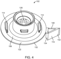
- the airflow guide 102 includes an air intake portion 106 and a cutwater 110 that extends from and is monolithically formed with the air intake portion 106. That is, the air intake portion 106 and the cutwater 110 may be co-molded or otherwise formed as a single piece.
- the airflow guide 102 is coupled to the housing 14 by mounting tabs 114 that extend from the airflow guide 102 and that are partially disposed in mounting pockets 118 formed in each of the clamshell halves 14a, 14b of the housing 14.
- the illustrated mounting tabs 114 are generally L-shaped.
- the illustrated airflow guide 102 includes two mounting tabs 114 although other quantities and configurations may be included.
- the air intake portion 106 includes a volute wall 122 and the mounting tabs 114 extend from the volute wall 122.
- the volute wall 122 is positioned in the air intake portion 18 and is disposed in close proximity to the impeller 98. As shown in FIGS. 3 and 4 , a passageway 126 is defined by an upper portion of the air intake portion 106 and extends from the volute wall 122 (e.g., in arcuate fashion) toward the intake port 54 in a first direction parallel to the intake port axis 54a. The passageway 126 defines the intake port 54 opposite the volute wall 122.
- the cutwater 110 extends from an edge 132 of the volute wall 122 in a second direction opposite the first direction.
- the cutwater 110 has a rounded edge 134.
- a volute face 138 and an exhaust face 142 extend from the rounded edge 134 and the volute face 138 and the exhaust face 142 are arranged relative to each other at an acute angle.
- the volute face 138 has an arcuate profile.
- the cutwater 110 has a generally triangular cross-section with a third face 146 that couples to the volute face 138 and the exhaust face 142.
- the passageway 126 is partially defined by an outer wall 150 and by an inner wall 154 that is coupled or joined to the outer wall 150 at a lower annular portion.
- the outer wall 150 has a first end 150a at which the outer wall 150 joins the volute wall 122, and a second end 150b opposite the first end 150a.
- the second end 150b is flush or substantially flush with the top surface 58 of the housing 14.
- the inner wall 154 extends radially inward from the first end 150a of the outer wall 150 and upward toward the second end 150b.
- Each of the illustrated outer wall 150 and the inner wall 154 are substantially cylindrical and an annular gap 158 is defined between the outer and inner walls 150, 154.
- the passageway 126 extends along an airflow axis 162.
- the inner wall 154 is arcuate in cross-section taken along the airflow axis 162 and has an inner surface 170 with a convex profile such that a central section 174 of the inner wall 154 is thicker than ends of the inner wall 154 (e.g., the inner wall 154 has a bell shape in cross-section).
- One or more ribs 178 (e.g., two ribs 178) extend across the passageway 126 between different portions of the inner wall 154.
- the illustrated ribs 178 have an inverted teardrop shape in cross-section, although the ribs 178 may have other cross-sectional shapes.
- the inflator 10 includes two ribs 178 that are spaced from each other to prevent ingress of larger objects, such as the finger of a user.
- the volute wall 122 has a transition 180 that defines an arcuate profile adjacent the first end 150a of the outer wall 150 to transition between the volute wall 122 and the inner wall 154.
- the nozzle 38 may be coupled to the intake port 54 to facilitate deflating an inflatable object. When the nozzle 38 is coupled to the intake port 54, the coupling portion 42 of the nozzle 38 is disposed in the gap 158.
- FIG. 8 illustrates the impeller 98 that has a first plate 182 (e.g., substantially circular) and that defines an impeller airflow opening 186, and a second plate 190 and a plurality of blades 194 that extend between the first plate 182 and the second plate 190.
- the first and second plates 182, 190 define circumferential edges and are rotatable with the blades 194 about an impeller axis 190b.
- the impeller 98 is rotatably supported in the housing 14 and the impeller axis 190b is axially aligned, or coaxial, with the airflow axis 162 (shown in FIGS. 6 and 11 ).
- Adjacent blades 194 define impeller channels 198, and the impeller 98 includes a hub 202 that is coupled to the output shaft 94 (e.g., by press-fit connection).
- the blades 194 have an arcuate profile and extend from adjacent the hub 202 to the circumferential edges of the first and second plates 182, 190.
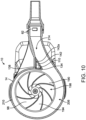
- the impeller 98 is positioned in the housing 14 such that the circumferential edge is adjacent the volute face 138 of the cutwater 110.
- the housing 14, the volute wall 122 of the air intake portion 106, and the cutwater 110 define a volute 206 between the intake port 54 and the outlet port 62.
- the impeller 98 is fluidly coupled to the volute 206 and the volute wall 122 is disposed flush with a portion of the volute 206 (e.g., an upper side of the volute 206 when viewed in FIG. 11 )
- a distance between the circumferential edges of the first and second plates 182, 190 and the outer surface of the volute 206 increases as the impeller 98 rotates in a counter-clockwise direction (as viewed in FIG. 10 ).
- An airflow channel 214 is in communication with the outlet port 62 and the volute 206 to distribute air to the outlet port 62.
- the exhaust face 142 of the cutwater 110 defines a guide surface 142a that partially defines the airflow channel 214. More specifically, the exhaust face 142 is positioned between the passageway 126 and the outlet port 62, and the exhaust face 142 extends from the rounded edge 134 and the volute wall 122 in a second direction relative to the first direction of the airflow axis 162.
- the rounded edge 134 defines an airflow separation location.
- the intake port 54 receives airflow through the intake port 54 generated by rotation of the impeller 98.
- the air intake portion 106 of the airflow guide 102 is shaped to direct airflow from the intake port 54 to the impeller 98, which distributes the airflow into the volute 206.
- the flush nature between the intake port 54 and the top surface 58 of the housing 14 reduces disruption of the airflow as the airflow enters the passageway 126.
- the arcuate-shaped inner surface 170 of the inner wall 154 concentrates the airflow as the airflow flows through the passageway 126. That is, the passageway 126 streamlines the incoming airflow into the inflator 10.
- the airflow enters the impeller airflow opening 186 by flowing along the volute wall 122 via the transition 180.
- the airflow is directed through the impeller channels 198 and exits the impeller channels 198 adjacent the circumferential edges of the first and second plates 182, 190.
- the airflow then flows through the volute 206.
- the rounded edge 134 separates the airflow from the volute 206.
- the separated airflow is guided through the airflow channel 214 by the exhaust face 142 and to the outlet port 62 of the housing 14.
- the cutwater 110 maintains a smooth airflow through the volute 206 and limits turbulence and recirculation of the airflow in the airflow channel 214, thereby attenuating sound of the airflow.
- a nozzle e.g., the nozzle 38
- the disclosure includes an inflator that has a housing including an intake port and an outlet port and at least partially defining a volute between the intake port and the outlet port.
- the disclosure includes an impeller is coupled to the housing and in airflow communication with the volute to generate an airflow through the volute.
- the disclosure includes an impeller is rotatably supported in the housing and in airflow communication with the volute to generate an airflow through the volute.
- the disclosure includes an impeller is rotatably supported in the housing and has a plurality of blades extending between a first plate and a second plate and defining impeller channels.
- the impeller channels have a channel height defined between a circumferential edge of the first plate and a circumferential edge of the second plate, and the impeller has an impeller height defined between the circumferential edge of the first plate and the circumferential edge of the second plate.
- the channel height is less than the distance defined between the impeller edge and the cutwater, and the distance defined between the circumferential edge of the second plate and the volute face is less than the impeller height.
- the disclosure includes an airflow guide is supported in the housing adjacent the impeller and has a cutwater and an air intake portion with a wall defining a passageway extending along an axis from the intake port to the impeller.
- the disclosure includes an airflow guide is disposed in the housing and has an air intake portion and a cutwater monolithically formed with the air intake portion.
- the air intake portion may be disposed flush with a portion of the volute and defines the intake port and a passageway extending from the intake port along an airflow axis.
- the cutwater may extend from the air intake portion and be disposed between the passageway and the outlet port adjacent a circumferential edge of the impeller.
- the passageway has a profile that decreases in cross-section at least partially along the axis.
- the disclosure includes a cutwater having a volute face at least partially defining the volute adjacent the circumferential edge of the second plate.
- the impeller is rotatable about an impeller axis that is coaxial with the airflow axis.
- the air intake portion defines a portion of the volute.
- the air intake portion includes a volute wall at least partially defining a surface of the volute, wherein the passageway extends in a first direction from the volute wall toward the intake port, and wherein the cutwater extends from the volute wall in a second direction toward the outlet port.
- the intake port includes an outer wall, an inner wall spaced from the outer wall by a gap, and wherein the inner wall has an inner surface with an arcuate profile.
- the arcuate profile is convex relative to the passageway.
- the air intake portion includes one or more ribs extending from the inner wall across the passageway.
- the gap is configured to receive a coupling portion of a nozzle.
- the airflow guide includes at least one mounting tab coupled to the housing.
- the profile decreases along a curved cross-section.
- the profile is defined by a convex inner surface of the wall.
- the wall is an inner wall of the air intake portion and the air intake portion further includes an outer wall spaced from the outer wall by a gap, and wherein the gap is configured to receive an end of a nozzle.
- the outer wall extends to the intake port and is flush with the intake port.
- the wall is an inner wall of the air intake portion and the air intake portion further includes a volute wall extending from the inner wall and defining a portion of the volute.
- the volute wall has an arcuate transition adjacent the inner wall.
- the profile is defined by a bell shape.
- the profile increases in cross-section at least partially along the axis following the decrease in the cross-section of the profile.
- the profile increases along a curved cross-section.
Landscapes
- Engineering & Computer Science (AREA)
- Mechanical Engineering (AREA)
- General Engineering & Computer Science (AREA)
- Structures Of Non-Positive Displacement Pumps (AREA)
- Jet Pumps And Other Pumps (AREA)
Abstract
Description
- The present disclosure relates to an inflator tool, and more particularly to a monolithic deflation port and cutwater.
- An inflator tool creates a high velocity airflow by pulling air into the volute of a tool housing by an impeller coupled to rotate with the output of a motor and directing the airflow out of the tool through an outlet. Various portions of the inflator tool affect the flow behavior, i.e., aerodynamic efficiency, performance, and acoustics, of the airflow through the inflator. At least two components of an inflator that affect the flow behavior are the deflation port and the cutwater. The geometry of the deflation port affects the airflow to the impeller. The cutwater separates rotational flow of air near the impeller and directs the flow toward the outlet.
- The present disclosure provides, in one aspect, an inflator including a housing, an impeller, and an airflow guide. The housing includes a intake port and a outlet port. A volute is defined between the first and outlet ports. The impeller is coupled to the housing. The impeller is in airflow communication with the volute and generates an airflow through the volute. The airflow guide is disposed in the housing and includes an air intake portion and a cutwater that is monolithically formed with the air intake portion. The air intake portion is disposed flush with a portion of the volute and defines the intake port. The air intake portion also defines a passageway extending from the intake port along an airflow axis. The cutwater extends from the air intake portion and is disposed between the passageway and the outlet port, adjacent a circumferential edge of the impeller.
- The present disclosure provides, in another aspect, an inflator including a housing, an impeller, and an airflow guide. The housing includes an inlet defined in the top surface of the housing, and an outlet that is spaced from the inlet. The impeller is rotatably supported in the housing and is configured to draw air into the housing through the inlet. The airflow guide is supported in the housing adjacent the impeller. The airflow guide includes a deflator portion. The deflator portion has a port inlet having an inlet diameter, and a port outlet having an outlet diameter. A channel is defined between the port inlet and the port outlet. The port inlet is positioned generally flush with the top surface of the housing. The outlet diameter is smaller than the inlet diameter.
- The present disclosure provides, in another aspect, an inflator including a housing, an impeller, and an airflow guide. The housing includes a intake port and a outlet port. A volute is defined between the first and outlet ports. The impeller is rotatably supported in the housing and is in airflow communicate with the volute. The impeller generates an airflow through the volute. The airflow guide is supported in the housing adjacent the impeller and includes a cutwater and an air intake portion. The air intake portion has a wall defining a passageway extending along an axis from the intake port to the impeller. The passageway has an arcuate profile in cross-section along the axis.
- The present disclosure provides, in another aspect, an airflow guide for an inflator tool that has a intake port and a outlet port. The airflow guide includes an air intake portion and a cutwater extending from the air intake portion. The air intake portion is shaped to direct an airflow relative to the intake port. The cutwater is monolithically formed with the air intake portion and is configured to guide the airflow toward the outlet port.
- Other features and aspects of the embodiments will become apparent by consideration of the following detailed description and accompanying drawings.
-
-
FIG. 1 is a perspective view illustrating an inflator according to the present disclosure. -
FIG. 2 is a section view illustrating the inflator according toFIG. 1 . -
FIG. 3 is an enlarged view illustrating the airflow guide, and impeller according toFIG. 1 -
FIG. 4 is a perspective view illustrating the airflow guide ofFIG. 1 . -
FIG. 5 is a bottom view illustrating the airflow guide according toFIG. 1 . -
FIG. 6 is a section view of the deflator portion of the airflow guide according toFIG. 1 . -
FIG. 7 is a section view illustrating the inflator according toFIG. 1 , including a nozzle coupled to the inflator. -
FIG. 8 is a perspective view illustrating the impeller according toFIG. 1 . -
FIG. 9 is a top view illustrating the inflator according toFIG. 1 . -
FIG. 10 is a section view illustrating the volute, impeller, and volute according toFIG. 4 . -
FIG. 11 is a section view illustrating the airflow guide and impeller according toFIG. 9 . -
FIG. 12 is a side section view illustrating an airflow path of the inflator according toFIG. 1 . -
FIG. 13 is a top section view illustrating an airflow path of the inflator according toFIG. 1 . - Before any exemplary embodiments are explained in detail, it is to be understood that the invention is not limited in its application to the details of construction and the arrangement of components set forth in the following description or illustrated in the following drawings. The invention is capable of other embodiments and of being practiced or of being carried out in various ways. Also, it is to be understood that the phraseology and terminology used herein is for the purpose of description and should not be regarded as limiting.
-
FIG. 1 illustrates a tool 10 (i.e., an inflator) according to the present disclosure. Theinflator 10 includes ahousing 14 that has anair intake portion 18, ahandle 22 extending from theair intake portion 18, and abattery connection portion 26 at adistal end 30 of thehandle 22. Thehousing 14 may be formed afirst clamshell half 14a coupled to a second clamshell half 14b (e.g., via fasteners, clips, or other fasteners, including adhesive). A battery pack (not shown) can be removably coupled to thebattery connection portion 26 to provide electrical power for theinflator 10. Atrigger 34 is supported on the handle 22 (e.g., below theair intake portion 18 as shown inFIG. 1 ). - A
nozzle 38 may be coupled to theinflator 10 and includes acoupling portion 42 and defines anair passageway 46 extending from thecoupling portion 42. Nozzles with different profiles or outlet sizes may be coupled to theinflator 10. Thehousing 14 includes anozzle storage location 50 extending from thebattery connection portion 26 that facilitates storage of thenozzle 38 or another nozzle (e.g., anozzle 38a) on thehousing 14. Thenozzle 38 may be used for deflation or inflation of an inflatable object. - The
housing 14 has anintake port 54 and anoutlet port 62. As shown inFIG. 2 , theintake port 54 is flush or substantially flush (e.g., defining a small lip) with atop surface 58 of the housing and is defined by theair intake portion 18, and theintake port 54 has anintake port axis 54a and theoutlet port 62 has anoutlet port axis 62a. Theintake port axis 54a is disposed at an angle relative to theoutlet port axis 62a (e.g., a 90-degree angle). Returning toFIG. 1 , thenozzle 38 can be coupled to the outlet port 62 (e.g., to facilitate inflation of an inflatable object). Thenozzle 38 includes atrack 74 that receives anode 78 that extends from theoutlet port 62. Thenozzle 38 is inserted onto theoutlet port 62 with thenode 78 received in thetrack 74. Thenozzle 38 is then rotated relative to theoutlet port 62 to secure thenozzle 38 to theoutlet port 62. - With reference to
FIG. 2 , aswitch 82 is supported in thehandle 22 adjacent theair intake portion 18. Thetrigger 34 engages theswitch 82, which is configured to activate theinflator 10. Thetrigger 34 is pivotally coupled to thehandle 22. Amotor 86 is supported in thehandle 22 of thehousing 14 adjacent theair intake portion 18. Themotor 86 is coupled to amotor mount 90 that is coupled to thehousing 14. Themotor 86 includes anoutput shaft 94 that extends from themotor 86. Theoutput shaft 94 rotates about amotor axis 94a. Animpeller 98 is coupled to theoutput shaft 94 and rotates with theoutput shaft 94. Theimpeller 98 is disposed in theair intake portion 18. Anairflow guide 102 is coupled to thehousing 14 in theair intake portion 18 adjacent to theimpeller 98. - With reference to
FIG. 3 , theairflow guide 102 includes anair intake portion 106 and acutwater 110 that extends from and is monolithically formed with theair intake portion 106. That is, theair intake portion 106 and thecutwater 110 may be co-molded or otherwise formed as a single piece. Theairflow guide 102 is coupled to thehousing 14 by mountingtabs 114 that extend from theairflow guide 102 and that are partially disposed in mountingpockets 118 formed in each of theclamshell halves housing 14. The illustrated mountingtabs 114 are generally L-shaped. The illustratedairflow guide 102 includes two mountingtabs 114 although other quantities and configurations may be included. As shown, theair intake portion 106 includes avolute wall 122 and the mountingtabs 114 extend from thevolute wall 122. - The
volute wall 122 is positioned in theair intake portion 18 and is disposed in close proximity to theimpeller 98. As shown inFIGS. 3 and4 , apassageway 126 is defined by an upper portion of theair intake portion 106 and extends from the volute wall 122 (e.g., in arcuate fashion) toward theintake port 54 in a first direction parallel to theintake port axis 54a. Thepassageway 126 defines theintake port 54 opposite thevolute wall 122. - With reference to
FIGS. 4 and5 , thecutwater 110 extends from anedge 132 of thevolute wall 122 in a second direction opposite the first direction. Thecutwater 110 has a roundededge 134. Avolute face 138 and anexhaust face 142 extend from therounded edge 134 and thevolute face 138 and theexhaust face 142 are arranged relative to each other at an acute angle. Thevolute face 138 has an arcuate profile. As shown, thecutwater 110 has a generally triangular cross-section with athird face 146 that couples to thevolute face 138 and theexhaust face 142. - With reference to
FIGS. 5 and6 , thepassageway 126 is partially defined by anouter wall 150 and by aninner wall 154 that is coupled or joined to theouter wall 150 at a lower annular portion. Theouter wall 150 has afirst end 150a at which theouter wall 150 joins thevolute wall 122, and asecond end 150b opposite thefirst end 150a. Thesecond end 150b is flush or substantially flush with thetop surface 58 of thehousing 14. Theinner wall 154 extends radially inward from thefirst end 150a of theouter wall 150 and upward toward thesecond end 150b. Each of the illustratedouter wall 150 and theinner wall 154 are substantially cylindrical and anannular gap 158 is defined between the outer andinner walls passageway 126 extends along anairflow axis 162. As shown inFIG. 6 , theinner wall 154 is arcuate in cross-section taken along theairflow axis 162 and has aninner surface 170 with a convex profile such that acentral section 174 of theinner wall 154 is thicker than ends of the inner wall 154 (e.g., theinner wall 154 has a bell shape in cross-section). One or more ribs 178 (e.g., two ribs 178) extend across thepassageway 126 between different portions of theinner wall 154. The illustratedribs 178 have an inverted teardrop shape in cross-section, although theribs 178 may have other cross-sectional shapes. As shown, theinflator 10 includes tworibs 178 that are spaced from each other to prevent ingress of larger objects, such as the finger of a user. Thevolute wall 122 has atransition 180 that defines an arcuate profile adjacent thefirst end 150a of theouter wall 150 to transition between thevolute wall 122 and theinner wall 154. With reference toFIG. 7 , thenozzle 38 may be coupled to theintake port 54 to facilitate deflating an inflatable object. When thenozzle 38 is coupled to theintake port 54, thecoupling portion 42 of thenozzle 38 is disposed in thegap 158. -
FIG. 8 illustrates theimpeller 98 that has a first plate 182 (e.g., substantially circular) and that defines animpeller airflow opening 186, and asecond plate 190 and a plurality ofblades 194 that extend between thefirst plate 182 and thesecond plate 190. The first andsecond plates blades 194 about animpeller axis 190b. Theimpeller 98 is rotatably supported in thehousing 14 and theimpeller axis 190b is axially aligned, or coaxial, with the airflow axis 162 (shown inFIGS. 6 and11 ).Adjacent blades 194 defineimpeller channels 198, and theimpeller 98 includes ahub 202 that is coupled to the output shaft 94 (e.g., by press-fit connection). With reference toFIGS. 8 and10 , theblades 194 have an arcuate profile and extend from adjacent thehub 202 to the circumferential edges of the first andsecond plates impeller 98 is positioned in thehousing 14 such that the circumferential edge is adjacent thevolute face 138 of thecutwater 110. - With reference to
FIGS. 10 and11 , thehousing 14, thevolute wall 122 of theair intake portion 106, and thecutwater 110 define avolute 206 between theintake port 54 and theoutlet port 62. Theimpeller 98 is fluidly coupled to thevolute 206 and thevolute wall 122 is disposed flush with a portion of the volute 206 (e.g., an upper side of thevolute 206 when viewed inFIG. 11 ) A distance between the circumferential edges of the first andsecond plates inner surface 210 of the housing 14) increases as theimpeller 98 rotates in a counter-clockwise direction (as viewed inFIG. 10 ). Anairflow channel 214 is in communication with theoutlet port 62 and thevolute 206 to distribute air to theoutlet port 62. Theexhaust face 142 of thecutwater 110 defines aguide surface 142a that partially defines theairflow channel 214. More specifically, theexhaust face 142 is positioned between thepassageway 126 and theoutlet port 62, and theexhaust face 142 extends from therounded edge 134 and thevolute wall 122 in a second direction relative to the first direction of theairflow axis 162. Therounded edge 134 defines an airflow separation location. - With reference to
FIG 12 , theintake port 54 receives airflow through theintake port 54 generated by rotation of theimpeller 98. Theair intake portion 106 of theairflow guide 102 is shaped to direct airflow from theintake port 54 to theimpeller 98, which distributes the airflow into thevolute 206. The flush nature between theintake port 54 and thetop surface 58 of thehousing 14 reduces disruption of the airflow as the airflow enters thepassageway 126. The arcuate-shapedinner surface 170 of theinner wall 154 concentrates the airflow as the airflow flows through thepassageway 126. That is, thepassageway 126 streamlines the incoming airflow into theinflator 10. The airflow enters theimpeller airflow opening 186 by flowing along thevolute wall 122 via thetransition 180. With reference toFIG. 13 , the airflow is directed through theimpeller channels 198 and exits theimpeller channels 198 adjacent the circumferential edges of the first andsecond plates volute 206. As the airflow reaches thecutwater 110, therounded edge 134 separates the airflow from thevolute 206. The separated airflow is guided through theairflow channel 214 by theexhaust face 142 and to theoutlet port 62 of thehousing 14. Thecutwater 110 maintains a smooth airflow through thevolute 206 and limits turbulence and recirculation of the airflow in theairflow channel 214, thereby attenuating sound of the airflow. A nozzle (e.g., the nozzle 38) may be coupled to theintake port 54 to facilitate deflation of an inflatable object, or a nozzle (e.g., the nozzle 38) may be coupled to theoutlet port 62 to facilitate inflation of an inflatable obj ect. - While the above example may be described in connection with an inflator tool with monolithic deflation port and cutwater structure, the deflation port and cutwater structure described herein may be applicable to other types of tools. Moreover, embodiments and limitations disclosed herein are not dedicated to the public under the doctrine of dedication if the embodiments an/or limitations: (1) are not expressly claimed in the claims; and (2) are or are potentially equivalents of express elements and/or limitations in the claims under the doctrine of equivalents.
- In an embodiment the disclosure includes an inflator that has a housing including an intake port and an outlet port and at least partially defining a volute between the intake port and the outlet port.
- In some embodiments, the disclosure includes an impeller is coupled to the housing and in airflow communication with the volute to generate an airflow through the volute.
- In some embodiments, the disclosure includes an impeller is rotatably supported in the housing and in airflow communication with the volute to generate an airflow through the volute.
- In some embodiments, the disclosure includes an impeller is rotatably supported in the housing and has a plurality of blades extending between a first plate and a second plate and defining impeller channels. The impeller channels have a channel height defined between a circumferential edge of the first plate and a circumferential edge of the second plate, and the impeller has an impeller height defined between the circumferential edge of the first plate and the circumferential edge of the second plate.
- In some embodiments, the channel height is less than the distance defined between the impeller edge and the cutwater, and the distance defined between the circumferential edge of the second plate and the volute face is less than the impeller height.
- In some embodiments, the disclosure includes an airflow guide is supported in the housing adjacent the impeller and has a cutwater and an air intake portion with a wall defining a passageway extending along an axis from the intake port to the impeller.
- In some embodiments, the disclosure includes an airflow guide is disposed in the housing and has an air intake portion and a cutwater monolithically formed with the air intake portion. The air intake portion may be disposed flush with a portion of the volute and defines the intake port and a passageway extending from the intake port along an airflow axis. The cutwater may extend from the air intake portion and be disposed between the passageway and the outlet port adjacent a circumferential edge of the impeller.
- In some embodiments of the disclosure, the passageway has a profile that decreases in cross-section at least partially along the axis.
- In some embodiments, the disclosure includes a cutwater having a volute face at least partially defining the volute adjacent the circumferential edge of the second plate.
- In some embodiments of the disclosure, the impeller is rotatable about an impeller axis that is coaxial with the airflow axis.
- In some embodiments of the disclosure, the air intake portion defines a portion of the volute.
- In some embodiments of the disclosure, the air intake portion includes a volute wall at least partially defining a surface of the volute, wherein the passageway extends in a first direction from the volute wall toward the intake port, and wherein the cutwater extends from the volute wall in a second direction toward the outlet port.
- In some embodiments of the disclosure, the intake port includes an outer wall, an inner wall spaced from the outer wall by a gap, and wherein the inner wall has an inner surface with an arcuate profile.
- In some embodiments of the disclosure, the arcuate profile is convex relative to the passageway.
- In some embodiments of the disclosure, the air intake portion includes one or more ribs extending from the inner wall across the passageway.
- In some embodiments of the disclosure, the gap is configured to receive a coupling portion of a nozzle.
- In some embodiments of the disclosure, the airflow guide includes at least one mounting tab coupled to the housing.
- In some embodiments of the disclosure, the profile decreases along a curved cross-section.
- In some embodiments of the disclosure, the profile is defined by a convex inner surface of the wall.
- In some embodiments of the disclosure, the wall is an inner wall of the air intake portion and the air intake portion further includes an outer wall spaced from the outer wall by a gap, and wherein the gap is configured to receive an end of a nozzle.
- In some embodiments of the disclosure, the outer wall extends to the intake port and is flush with the intake port.
- In some embodiments of the disclosure, the wall is an inner wall of the air intake portion and the air intake portion further includes a volute wall extending from the inner wall and defining a portion of the volute.
- In some embodiments of the disclosure, the volute wall has an arcuate transition adjacent the inner wall.
- In some embodiments of the disclosure, the profile is defined by a bell shape.
- In some embodiments of the disclosure, the profile increases in cross-section at least partially along the axis following the decrease in the cross-section of the profile.
- In some embodiments of the disclosure, the profile increases along a curved cross-section.
Claims (15)
- An inflator comprising:a housing including an intake port and an outlet port and at least partially defining a volute between the intake port and the outlet port;an impeller coupled to the housing and in airflow communication with the volute to generate an airflow through the volute; andan airflow guide disposed in the housing and including an air intake portion and a cutwater monolithically formed with the air intake portion, the air intake portion disposed flush with a portion of the volute and defining the intake port and a passageway extending from the intake port along an airflow axis, and the cutwater extending from the air intake portion and disposed between the passageway and the outlet port adjacent a circumferential edge of the impeller.
- The inflator of claim 1, wherein the impeller is rotatable about an impeller axis that is coaxial with the airflow axis.
- The inflator of claim 1, wherein the air intake portion defines a portion of the volute.
- The inflator of claim 1, wherein the air intake portion includes a volute wall at least partially defining a surface of the volute, wherein the passageway extends in a first direction from the volute wall toward the intake port, and wherein the cutwater extends from the volute wall in a second direction toward the outlet port.
- The inflator of claim 1, wherein the intake port includes an outer wall, an inner wall spaced from the outer wall by a gap, and wherein the inner wall has an inner surface with an arcuate profile;
and optionally,wherein the arcuate profile is convex relative to the passageway.
wherein the air intake portion includes one or more ribs extending from the inner wall across the passageway;wherein the gap is configured to receive a coupling portion of a nozzle. - The inflator of claim 1, wherein the airflow guide includes at least one mounting tab coupled to the housing.
- An inflator comprising:a housing including an intake port and an outlet port and defining a volute between the intake port and the outlet port;an impeller rotatably supported in the housing and in airflow communication with the volute to generate an airflow through the volute; andan airflow guide supported in the housing adjacent the impeller, the airflow guide including a cutwater and an air intake portion having a wall defining a passageway extending along an axis from the intake port to the impeller,wherein the passageway has a profile that decreases in cross-section at least partially along the axis.
- The inflator of claim 7, wherein the profile decreases along a curved cross-section;
and optionally,
the profile is defined by a convex inner surface of the wall. - The inflator of claim 7, wherein the wall is an inner wall of the air intake portion and the air intake portion further includes an outer wall spaced from the outer wall by a gap, and wherein the gap is configured to receive an end of a nozzle.
- The inflator of claim 9, wherein the outer wall extends to the intake port and is flush with the intake port.
- The inflator of claim 7, wherein the wall is an inner wall of the air intake portion and the air intake portion further includes a volute wall extending from the inner wall and defining a portion of the volute;
and optionally,
wherein the volute wall has an arcuate transition adjacent the inner wall. - The inflator of claim 8, wherein the profile is defined by a bell shape.
- The inflator of claim 7, wherein the profile increases in cross-section at least partially along the axis following the decrease in the cross-section of the profile.
- The inflator of claim 13, wherein the profile increases along a curved cross-section.
- An inflator comprising:a housing including an intake port and an outlet port and at least partially defining a volute between the intake port and the outlet port;an impeller rotatably supported in the housing, the impeller including a plurality of blades extending between a first plate and a second plate and defining impeller channels, the impeller channels having a channel height defined between a circumferential edge of the first plate and a circumferential edge of the second plate, and the impeller having an impeller height defined between the circumferential edge of the first plate and the circumferential edge of the second plate;a cutwater having a volute face at least partially defining the volute adjacent the circumferential edge of the second plate; andwherein the channel height is less than the distance defined between the impeller edge and the cutwater, and the distance defined between the circumferential edge of the second plate and the volute face is less than the impeller height.
Applications Claiming Priority (1)
| Application Number | Priority Date | Filing Date | Title |
|---|---|---|---|
| US17/879,503 US12071958B2 (en) | 2022-08-02 | 2022-08-02 | Inflator having combined cutwater and intake/exhaust port |
Publications (2)
| Publication Number | Publication Date |
|---|---|
| EP4317700A2 true EP4317700A2 (en) | 2024-02-07 |
| EP4317700A3 EP4317700A3 (en) | 2024-04-03 |
Family
ID=87429176
Family Applications (1)
| Application Number | Title | Priority Date | Filing Date |
|---|---|---|---|
| EP23187076.7A Pending EP4317700A3 (en) | 2022-08-02 | 2023-07-21 | Inflator having combined cutwater and intake/exhaust port |
Country Status (5)
| Country | Link |
|---|---|
| US (2) | US12071958B2 (en) |
| EP (1) | EP4317700A3 (en) |
| CN (1) | CN117489610A (en) |
| CA (1) | CA3207693A1 (en) |
| MX (1) | MX2023008999A (en) |
Family Cites Families (22)
| Publication number | Priority date | Publication date | Assignee | Title |
|---|---|---|---|---|
| US5120193A (en) | 1990-02-26 | 1992-06-09 | General Motors Corporation | Baffle for reducing airflow noise in a scroll housing |
| US5286162A (en) * | 1993-01-04 | 1994-02-15 | The United States Of America As Represented By The Administrator Of The National Aeronautics And Space Administration | Method of reducing hydraulic instability |
| US6045341A (en) * | 1998-07-14 | 2000-04-04 | Hop Lee Cheong Industrial Company Limited | Levitation blower |
| US6155781A (en) * | 1999-04-02 | 2000-12-05 | Tsai; Cheng-Chang | Portable electric air pump |
| JP4026366B2 (en) * | 2001-03-16 | 2007-12-26 | 株式会社デンソー | Centrifugal blower |
| US6955529B2 (en) * | 2003-12-11 | 2005-10-18 | Ho Lee Co., Ltd. | Bidirectional air pump assembly for inflatable objects |
| CN2731153Y (en) | 2004-09-22 | 2005-10-05 | 宋荣治 | Bidirectional pump |
| US7284968B2 (en) | 2004-09-28 | 2007-10-23 | Ho Lee Co., Ltd. | Bidirectional air pump |
| TWI267584B (en) * | 2004-11-05 | 2006-12-01 | Quanta Comp Inc | Centrifugal fan |
| CN2773356Y (en) * | 2005-03-02 | 2006-04-19 | 巫新财 | Air transferring device with adjustable air transferring mouth |
| US7597541B2 (en) * | 2005-07-12 | 2009-10-06 | Robert Bosch Llc | Centrifugal fan assembly |
| CN101649845B (en) * | 2008-08-13 | 2013-02-20 | 富准精密工业(深圳)有限公司 | Centrifugal fan |
| CN101672299B (en) * | 2008-09-12 | 2012-09-19 | 富准精密工业(深圳)有限公司 | Eccentric fan |
| CN101725573B (en) * | 2008-10-13 | 2013-04-24 | 富准精密工业(深圳)有限公司 | Centrifugal fan |
| DE102008051362A1 (en) | 2008-10-15 | 2010-04-22 | Behr Gmbh & Co. Kg | Radial blower housing |
| US8678131B2 (en) * | 2012-03-30 | 2014-03-25 | Textron Innovations Inc. | Acoustic baffle for centrifugal blowers |
| JP6073604B2 (en) * | 2012-09-03 | 2017-02-01 | サンデンホールディングス株式会社 | Centrifugal blower |
| CN107850084B (en) * | 2015-08-06 | 2022-01-14 | 三菱电机株式会社 | Centrifugal blower, air conditioner, and refrigeration cycle device |
| AU2018200068B2 (en) * | 2017-01-04 | 2019-04-18 | Tti (Macao Commercial Offshore) Limited | Inflator |
| WO2019082392A1 (en) * | 2017-10-27 | 2019-05-02 | 三菱電機株式会社 | Centrifugal blower, air blower device, air conditioning device, and refrigeration cycle device |
| CN110439860B (en) * | 2018-05-04 | 2025-04-15 | 宁波方太厨具有限公司 | A volute structure of a centrifugal fan |
| RU2721205C1 (en) * | 2018-12-24 | 2020-05-18 | Виталий Валериевич Кожевин | Impeller for vehicle |
-
2022
- 2022-08-02 US US17/879,503 patent/US12071958B2/en active Active
-
2023
- 2023-07-21 EP EP23187076.7A patent/EP4317700A3/en active Pending
- 2023-07-26 CN CN202310924804.XA patent/CN117489610A/en active Pending
- 2023-07-27 CA CA3207693A patent/CA3207693A1/en active Pending
- 2023-07-31 MX MX2023008999A patent/MX2023008999A/en unknown
-
2024
- 2024-08-19 US US18/808,917 patent/US12663017B2/en active Active
Also Published As
| Publication number | Publication date |
|---|---|
| MX2023008999A (en) | 2024-02-05 |
| CN117489610A (en) | 2024-02-02 |
| EP4317700A3 (en) | 2024-04-03 |
| CA3207693A1 (en) | 2024-02-02 |
| US20240410391A1 (en) | 2024-12-12 |
| US12071958B2 (en) | 2024-08-27 |
| US20240044340A1 (en) | 2024-02-08 |
| US12663017B2 (en) | 2026-06-23 |
Similar Documents
| Publication | Publication Date | Title |
|---|---|---|
| EP3872349B1 (en) | Blower with a tapered member placed between inlet and motor | |
| KR100625416B1 (en) | Centrifugal blower | |
| US10337522B2 (en) | Centrifugal compressor | |
| EP2975269B1 (en) | Centrifugal compressor | |
| CN112424480B (en) | Axial fan | |
| US7500825B2 (en) | Centrifugal blower | |
| CN202789707U (en) | Centrifugal blower | |
| TWI460352B (en) | Electric blower and equipped with its electric vacuum cleaner | |
| CA1219245A (en) | Single-stage, multiple outlet centrifugal blower | |
| US20120219437A1 (en) | Electric blower and electric cleaner using same | |
| KR20170048308A (en) | Blower and outdoor unit of air conditioner having the same | |
| WO2014034950A1 (en) | Centrifugal air blower | |
| WO2021084875A1 (en) | Electric blower and vacuum cleaner provided with same | |
| TWI468597B (en) | Electric blower and vacuum cleaner equipped with electric blower | |
| EP1953391B1 (en) | Multi-vane centrifugal blower | |
| JP2004144029A (en) | Centrifugal compressor for turbocharger | |
| US20020004008A1 (en) | Centrifugal fan | |
| WO2017090480A1 (en) | Cyclone dust collector | |
| US12071958B2 (en) | Inflator having combined cutwater and intake/exhaust port | |
| JP6758243B2 (en) | Electric blower and vacuum cleaner equipped with it | |
| TWI401365B (en) | An electric blower, an electric vacuum cleaner loaded with the electric blower, and a method of manufacturing the same | |
| EP1618821B1 (en) | Centrifugal fan and vacuum cleaner having the centrifugal fan | |
| JP3607769B2 (en) | Centrifugal blower | |
| JP2003035294A (en) | Impeller of multi-blade blower and multi-blade blower provided with the same | |
| CN220522838U (en) | Centrifugal fan |
Legal Events
| Date | Code | Title | Description |
|---|---|---|---|
| PUAI | Public reference made under article 153(3) epc to a published international application that has entered the european phase |
Free format text: ORIGINAL CODE: 0009012 |
|
| STAA | Information on the status of an ep patent application or granted ep patent |
Free format text: STATUS: THE APPLICATION HAS BEEN PUBLISHED |
|
| AK | Designated contracting states |
Kind code of ref document: A2 Designated state(s): AL AT BE BG CH CY CZ DE DK EE ES FI FR GB GR HR HU IE IS IT LI LT LU LV MC ME MK MT NL NO PL PT RO RS SE SI SK SM TR |
|
| PUAL | Search report despatched |
Free format text: ORIGINAL CODE: 0009013 |
|
| AK | Designated contracting states |
Kind code of ref document: A3 Designated state(s): AL AT BE BG CH CY CZ DE DK EE ES FI FR GB GR HR HU IE IS IT LI LT LU LV MC ME MK MT NL NO PL PT RO RS SE SI SK SM TR |
|
| RIC1 | Information provided on ipc code assigned before grant |
Ipc: F04D 29/42 20060101ALI20240229BHEP Ipc: F04D 25/08 20060101AFI20240229BHEP |
|
| STAA | Information on the status of an ep patent application or granted ep patent |
Free format text: STATUS: REQUEST FOR EXAMINATION WAS MADE |
|
| 17P | Request for examination filed |
Effective date: 20241004 |
|
| RBV | Designated contracting states (corrected) |
Designated state(s): AL AT BE BG CH CY CZ DE DK EE ES FI FR GB GR HR HU IE IS IT LI LT LU LV MC ME MK MT NL NO PL PT RO RS SE SI SK SM TR |
|
| GRAP | Despatch of communication of intention to grant a patent |
Free format text: ORIGINAL CODE: EPIDOSNIGR1 |
|
| STAA | Information on the status of an ep patent application or granted ep patent |
Free format text: STATUS: GRANT OF PATENT IS INTENDED |
|
| INTG | Intention to grant announced |
Effective date: 20260615 |