EP4317686A1 - Shutoff control system for compression apparatus, heat-pump apparatus, device and driving system - Google Patents
Shutoff control system for compression apparatus, heat-pump apparatus, device and driving system Download PDFInfo
- Publication number
- EP4317686A1 EP4317686A1 EP23190017.6A EP23190017A EP4317686A1 EP 4317686 A1 EP4317686 A1 EP 4317686A1 EP 23190017 A EP23190017 A EP 23190017A EP 4317686 A1 EP4317686 A1 EP 4317686A1
- Authority
- EP
- European Patent Office
- Prior art keywords
- signal
- driving
- chip
- shutoff
- control
- Prior art date
- Legal status (The legal status is an assumption and is not a legal conclusion. Google has not performed a legal analysis and makes no representation as to the accuracy of the status listed.)
- Granted
Links
Images



Classifications
-
- F—MECHANICAL ENGINEERING; LIGHTING; HEATING; WEAPONS; BLASTING
- F04—POSITIVE - DISPLACEMENT MACHINES FOR LIQUIDS; PUMPS FOR LIQUIDS OR ELASTIC FLUIDS
- F04B—POSITIVE-DISPLACEMENT MACHINES FOR LIQUIDS; PUMPS
- F04B49/00—Control, e.g. of pump delivery, or pump pressure of, or safety measures for, machines, pumps, or pumping installations, not otherwise provided for, or of interest apart from, groups F04B1/00 - F04B47/00
- F04B49/08—Regulating by delivery pressure
-
- F—MECHANICAL ENGINEERING; LIGHTING; HEATING; WEAPONS; BLASTING
- F04—POSITIVE - DISPLACEMENT MACHINES FOR LIQUIDS; PUMPS FOR LIQUIDS OR ELASTIC FLUIDS
- F04B—POSITIVE-DISPLACEMENT MACHINES FOR LIQUIDS; PUMPS
- F04B49/00—Control, e.g. of pump delivery, or pump pressure of, or safety measures for, machines, pumps, or pumping installations, not otherwise provided for, or of interest apart from, groups F04B1/00 - F04B47/00
- F04B49/06—Control using electricity
- F04B49/065—Control using electricity and making use of computers
-
- F—MECHANICAL ENGINEERING; LIGHTING; HEATING; WEAPONS; BLASTING
- F04—POSITIVE - DISPLACEMENT MACHINES FOR LIQUIDS; PUMPS FOR LIQUIDS OR ELASTIC FLUIDS
- F04B—POSITIVE-DISPLACEMENT MACHINES FOR LIQUIDS; PUMPS
- F04B41/00—Pumping installations or systems specially adapted for elastic fluids
- F04B41/02—Pumping installations or systems specially adapted for elastic fluids having reservoirs
-
- F—MECHANICAL ENGINEERING; LIGHTING; HEATING; WEAPONS; BLASTING
- F04—POSITIVE - DISPLACEMENT MACHINES FOR LIQUIDS; PUMPS FOR LIQUIDS OR ELASTIC FLUIDS
- F04B—POSITIVE-DISPLACEMENT MACHINES FOR LIQUIDS; PUMPS
- F04B49/00—Control, e.g. of pump delivery, or pump pressure of, or safety measures for, machines, pumps, or pumping installations, not otherwise provided for, or of interest apart from, groups F04B1/00 - F04B47/00
- F04B49/02—Stopping, starting, unloading or idling control
- F04B49/022—Stopping, starting, unloading or idling control by means of pressure
-
- F—MECHANICAL ENGINEERING; LIGHTING; HEATING; WEAPONS; BLASTING
- F04—POSITIVE - DISPLACEMENT MACHINES FOR LIQUIDS; PUMPS FOR LIQUIDS OR ELASTIC FLUIDS
- F04B—POSITIVE-DISPLACEMENT MACHINES FOR LIQUIDS; PUMPS
- F04B49/00—Control, e.g. of pump delivery, or pump pressure of, or safety measures for, machines, pumps, or pumping installations, not otherwise provided for, or of interest apart from, groups F04B1/00 - F04B47/00
- F04B49/06—Control using electricity
-
- F—MECHANICAL ENGINEERING; LIGHTING; HEATING; WEAPONS; BLASTING
- F04—POSITIVE - DISPLACEMENT MACHINES FOR LIQUIDS; PUMPS FOR LIQUIDS OR ELASTIC FLUIDS
- F04B—POSITIVE-DISPLACEMENT MACHINES FOR LIQUIDS; PUMPS
- F04B49/00—Control, e.g. of pump delivery, or pump pressure of, or safety measures for, machines, pumps, or pumping installations, not otherwise provided for, or of interest apart from, groups F04B1/00 - F04B47/00
- F04B49/10—Other safety measures
-
- F—MECHANICAL ENGINEERING; LIGHTING; HEATING; WEAPONS; BLASTING
- F25—REFRIGERATION OR COOLING; COMBINED HEATING AND REFRIGERATION SYSTEMS; HEAT PUMP SYSTEMS; MANUFACTURE OR STORAGE OF ICE; LIQUEFACTION SOLIDIFICATION OF GASES
- F25B—REFRIGERATION MACHINES, PLANTS OR SYSTEMS; COMBINED HEATING AND REFRIGERATION SYSTEMS; HEAT PUMP SYSTEMS
- F25B49/00—Arrangement or mounting of control or safety devices
- F25B49/02—Arrangement or mounting of control or safety devices for compression type machines, plants or systems
- F25B49/022—Compressor control arrangements
Definitions
- This disclosure relates to control technologies, in particular to a shutoff control system for a compression apparatus, a heat-pump apparatus, a device, and a driving system.
- the compression apparatus (including a compressor and a pressure vessel, where a pressure in the pressure vessel changes when the compressor works) is an important part of an air conditioning system and a heat-pump system.
- a system containing the compression apparatus when the system has a high pressure, the pressure in the system will increase continuously if no action is taken to shut off the compression apparatus, resulting in the occurrence of dangers.
- the existing way to shut off the compression apparatus is collecting, by a main control board, a switch signal of the compression apparatus, then outputting, by the main control board, a signal to a module board according to the switch signal, and controlling, by the module board, the compression apparatus to shut off.
- This way of shutting off the compression apparatus involves many components and has a slow response speed, and the compression apparatus cannot be shut off as long as any one of the components is damaged, resulting in serious consequences.
- This disclosure provides a shutoff control system for a compression apparatus, a heat-pump apparatus, a device and a driving system, which are used to increase the success rate of shutting off the compression apparatus and improve the safety of the air conditioning system and the heat-pump system.
- this disclosure provides a shutoff control system for a compression apparatus, including:
- An embodiment of this disclosure provides a shutoff control system for a compression apparatus, including a pressure switch apparatus and a control apparatus.
- the pressure switch apparatus is configured to be shut off when a pressure of a system is detected to be overpressured, and output a shutoff signal.
- the control apparatus is in signal connection with the driving apparatus and the pressure switch apparatus, and is configured to output the first driving signal to drive the driving apparatus to work, and is configured to stop outputting the first driving signal after receiving the shutoff signal.
- the first driving signal is configured to drive the driving apparatus to work. Therefore, when the system is overpressured, the control apparatus controls the driving apparatus of the compression apparatus to stop outputting the driving signal, so as to control the compression apparatus to be shut off.
- system further includes: a signal output control apparatus, connected with the pressure switch apparatus and the control apparatus, respectively, and configured to control the control apparatus to stop outputting the first driving signal according to the shutoff signal.
- the signal output control apparatus includes a first chip and a second chip.
- the first chip is connected to the pressure switch apparatus, and the first chip is configured to output a reset signal to the second chip according to the shutoff signal.
- the second chip is in signal connection with the control apparatus, and the second chip is configured to control the control apparatus to stop outputting the first driving signal according to the reset signal.
- the first chip is specifically configured to:
- system further includes: a signal transmission circuit, with one end connected to an output end of the control apparatus for obtaining the output signal, and the other end connected to an input end of the first chip.
- the shutoff control system for the compression apparatus further includes a signal output control apparatus, and the signal output control apparatus includes a first chip and a second chip.
- the first chip is configured to output a reset signal to the second chip according to the shutoff signal
- the second chip is configured to control the control apparatus to stop outputting the first driving signal according to the reset signal.
- an enable pin of the control apparatus is further connected to a first power supply, and the pressure switch apparatus includes:
- a fourth end of the isolator is further connected to a second power supply, and a first pin of the first chip and a second pin of the first chip;
- the isolator is an optocoupler isolator.
- the first chip includes a reset feedback pin
- the second chip is configured to send a reset feedback signal to the reset feedback pin after the second chip receives the reset signal, and the reset feedback signal is configured to indicate that the second chip has successfully received the reset signal.
- the pressure switch apparatus includes an isolator and a pressure switch.
- the pressure switch is first shut off, thereby causing the isolator to fail to be turned on.
- the first power supply connected to the isolator outputs a pressure signal to the enable pin of the control apparatus, so that the control apparatus receives the shutoff signal and stops outputting the first driving signal.
- control apparatus includes N bridge arm pulse width modulation PWM circuits, and each bridge arm PWM circuit of the N bridge arm PWM circuits has different turn-on time; N is an integer greater than 1.
- each bridge arm PWM circuit includes a triode.
- the system further includes a first protective apparatus and a second protective apparatus; one end of the first protective apparatus and one end of the second protective apparatus are both connected to the driving apparatus, and the other end of the first protective apparatus and the other end of the second protective apparatus are both connected to the control apparatus, and both of the first protective apparatus and the second protective apparatus are configured to buffer an output of the control apparatus.
- the first protective apparatus includes:
- the second protective apparatus includes:
- system further includes: the driving apparatus, connected to the compression apparatus when the driving apparatus is in use, and configured to output the second driving signal to the compression apparatus after the driving apparatus receives the first driving signal; the second driving signal is configured to drive the compression apparatus to work.
- this disclosure provides a heat-pump apparatus, including the shutoff control system for the compression apparatus as provided in the first aspect, and further including:
- this disclosure provides an electrical device, including the heat-pump apparatus as provided in the second aspect.
- this disclosure provides a driving system, including the shutoff control system for the compression apparatus as provided in the first aspect, and further including: the driving apparatus, connected to the compression apparatus when the driving apparatus is in use, and configured to output the second driving signal to the compression apparatus after the driving apparatus receives the first driving signal; the second driving signal is configured to drive the compression apparatus to work.
- the control apparatus controls the driving apparatus of the compression apparatus to stop outputting the driving signal, so as to control the shutoff of the compression apparatus when the system is overpressured.
- the control apparatus controls the driving apparatus of the compression apparatus to stop outputting the driving signal, so as to control the shutoff of the compression apparatus when the system is overpressured.
- first and second are used for description purposes only, and cannot be interpreted as indicating or implying relative importance or implicitly indicating the number of indicated technical features. Thus, features defined with “first” and “second” may explicitly or implicitly include one or more of these features.
- “plurality” means two or more, unless otherwise specifically defined.
- the compression apparatus (including a compressor and a pressure vessel, where a pressure in the pressure vessel changes when the compressor works) is an important part of an air conditioning system and a heat-pump system.
- a system containing the compression apparatus when the system has a high pressure, the pressure in the system will increase continuously if no action is taken to shut off the compression apparatus, resulting in the occurrence of dangers.
- the existing way to shut off the compression apparatus is collecting, by a main control board, a switch signal of the compression apparatus, then outputting, by the main control board, a signal to a module board according to the switch signal, and controlling, by the module board, the compression apparatus to shut off.
- This way of shutting off the compression apparatus involves many components and has a slow response speed, and the compression apparatus cannot be shut off as long as any one of the components is damaged, resulting in serious consequences. Therefore, how to improve the efficiency and success rate of shutting off the compression apparatus and to improve the safety factor of the air conditioning system and the heat-pump system are still need to be solved.
- the shutoff control system for the compression apparatus includes a pressure switch apparatus, a driving apparatus, and a control apparatus.
- the pressure switch apparatus is configured to be shut off when the pressure switch apparatus detects a pressure of a system to be overpressured, and output a shutoff signal.
- the driving apparatus is connected to the compression apparatus (the compression apparatus is a compressor), and the driving apparatus, after receiving a first driving signal, outputs a second driving signal to the compression apparatus, and the second driving signal is configured to drive the compression apparatus to work.
- the control apparatus (such as a logic chip) is connected with the driving apparatus and the pressure switch apparatus for outputting the first driving signal to the driving apparatus, and stopping outputting the first driving signal after the control apparatus receives the shutoff signal.
- the control apparatus of the driving apparatus of the compressor stops outputting the driving signal, so that the driving apparatus no longer drives the compressor to work, thereby achieving the purpose of shutting off the compression apparatus.
- the shutoff control system for the compression apparatus provided by this disclosure involves fewer components, and the compression apparatus is mechanically driven rather than program-driven when the compression apparatus is shut off, thereby improving the efficiency and success rate of shutting off the compression apparatus and improving the safety factor of the air conditioning system and the heat-pump system.
- an embodiment of this disclosure provides a shutoff control system 10 for a compression apparatus
- the shutoff control system 10 is configured to control the shutoff of the compression apparatus 20 (i.e. a compressor), especially to control the shutoff of the compression apparatus 20 when a system is overpressured, that is, the compression apparatus 20 is controlled to be shut off when the system is overpressured.
- the pressure of the system may be a pressure of a part of the system, for example, the pressure of the system refers to the pressure of some components connected to the compressor in an air conditioner.
- the compression apparatus 20 is controlled to be shut off, thereby preventing a dangerous situation of continuous rise in pressure caused by the compression apparatus 20.
- the shutoff control system 10 for the compression apparatus comprises a pressure switch apparatus 100, and a control apparatus 300 connected to a driving apparatus 200 of the compression apparatus 20.
- the driving apparatus 200 is connected to the compression apparatus 20, and the driving apparatus 200 can be understood as a compressor driving module.
- the driving apparatus 200 is configured to, after receiving a first driving signal, output a second driving signal to the compression apparatus 20, and the second driving signal is configured to drive the compression apparatus 20 to work. If there is no first driving signal, the driving apparatus 200 will not output the second driving signal, and thus will not drive the compression apparatus 20 to work.
- the pressure switch apparatus 100 is configured to be shut off when the pressure switch apparatus detects that the system is overpressured, and output a shutoff signal.
- the pressure switch apparatus 100 is, for example, a switch portion in a device for detecting whether the system is overpressured. When the system is not overpressured, that is, when the system is running normally, the pressure switch apparatus 100 is in a normally closed state. When the system is detected to be overpressured, the pressure switch apparatus 100 is shut off under an overpressure impact. In an optional embodiment, when the system is not overpressured, that is, when the system is running normally, the pressure switch apparatus 100 is in a normally open state, and when the system is detected to be overpressured, the pressure switch apparatus 100 is closed under an overpressure impact. Therefore, the pressure switch apparatus 100 needs, when the system is overpressured, to be in a state opposite to the state thereof when the system is in a normal operation, so that the shutoff signal can be output to make other apparatuses obtain information about the system is overpressured.
- the control apparatus 300 is connected to the driving apparatus 200 and the pressure switch apparatus 100.
- the control apparatus 300 is configured to output the first driving signal to the driving apparatus 200, and stop outputting the first driving signal after the control apparatus 300 receives the shutoff signal.
- the first driving signal is configured to instruct the driving apparatus 200 to drive the compression apparatus 20 to work, and after the control apparatus 300 stops outputting the first driving signal, the driving apparatus 200 stops outputting the second driving signal to the compression apparatus 20, thereby achieving the purpose of shutting off the compression apparatus 20.
- the control apparatus 300 is, for example, a logic chip, and mechanically triggers the stop of outputting the first driving signal after the control apparatus 300 receives the shutoff signal.
- this example provides the shutoff control system 10 for the compression apparatus, including the pressure switch apparatus 100 and the control apparatus 300.
- the pressure switch apparatus 100 is configured to be shut off when the pressure switch apparatus 100 detects that the system is overpressured, and output the shutoff signal.
- the control apparatus 300 is in signal connection with the driving apparatus 200 and the pressure switch apparatus 100, and is configured to output the first driving signal to the driving apparatus 200, and is also configured to stop outputting the first driving signal after the control apparatus 300 receives the shutoff signal.
- the first driving signal is configured to drive the driving apparatus to work. Therefore, when the system is overpressured, the control apparatus 300 controls the driving apparatus 200 of the compression apparatus 20 to stop outputting the driving signal, thereby controlling the compression apparatus 20 to shut off.
- the control apparatus 300 firstly outputs the first driving signal to the driving apparatus 200, and then the driving apparatus 200, under the action of the first driving signal, outputs the second driving signal to the compression apparatus 20.
- the process that the compression apparatus 20 recovers normal operation has a time buffer, which can prevent a sudden damage of the compression apparatus 20 caused by the system's sudden recovery to normal operation.
- the shutoff control system 10 for the compression apparatus further includes a signal output control apparatus 400, and the signal output control apparatus 400 is connected with the pressure switch apparatus 100 and the control apparatus 300.
- the signal output control apparatus 400 is configured to control the control apparatus 300 to stop outputting the first driving signal according to the shutoff signal.
- the signal output control apparatus 400 includes, for example, a single-chip microcontroller unit (MCU for short) that drives the control apparatus 300, and the MCU, after receiving the shutoff signal, stops outputting a driving signal to the control apparatus 300, thereby controlling the control apparatus 300 to stop outputting the first driving signal.
- MCU microcontroller unit
- the signal output control apparatus 400 includes a first chip 410 and a second chip 420.
- the first chip 410 is connected to the pressure switch apparatus 100, and the first chip 410 is configured to output a reset signal to the second chip 420 according to the shutoff signal.
- the second chip 420 is in signal connection with the control apparatus 300, and the second chip 420 is configured to control the control apparatus 300 to stop outputting the first driving signal according to the reset signal.
- the second chip 420 is further configured to output a driving signal to drive the control apparatus 300.
- the purpose for the first chip 410 to output the reset signal to the second chip 420 is to prevent the situation in which the control apparatus 300, after receiving the shutoff signal, does not stop outputting the first driving signal, and the control apparatus 300 is controlled to stop outputting the first driving signal through the second chip 420.
- the first chip 410 when the first chip 410 is specifically configured to obtain the shutoff signal, the first chip 410 also obtains an output signal of the control apparatus 300.
- the first chip 410 When the obtained output signal of the control apparatus 300 is the first driving signal, the first chip 410 outputs the reset signal to the second chip 420, and the second chip 420, after receiving the reset signal, stops outputting the driving signal to the control apparatus 300.
- the first chip 410 determines that the output signal of the control apparatus 300 is the first driving signal
- the first chip 410 outputs a signal for indicating the control apparatus is in fault to the second chip 420 through a pin.
- the second chip 420 is provided with a pin for receiving the reset signal, and the first chip 410 sends, by the pin for outputting the reset signal, the reset signal to the pin (RESET, RST) for receiving the reset signal on the second chip 420.
- the second chip 420 is further provided with a reset feedback pin
- the first chip 410 is further provided with a pin for receiving a feedback signal.
- the second chip 420 is configured to send the reset feedback signal to the first chip 410 through the reset feedback pin after the second chip 420 receives the reset signal.
- the reset feedback signal is configured to indicate that the second chip 420 has successfully received the reset signal, so the first chip 410 knows that the second chip 420 stops outputting the driving signal after the second chip 420 receives the reset feedback signal.
- the shutoff control system 10 for the compression apparatus further includes a signal transmission circuit 500, and one end of the signal transmission circuit 500 is connected to an output end of the control apparatus 300, and is configured to obtain the output signal of the control apparatus 300.
- the other end of the signal transmission circuit 500 is connected to an input end of the first chip 410.
- the signal transmission circuit 500 is configured to transmit the output signal of the control apparatus 300 to the first chip 410.
- the signal transmission circuit 500 includes a resistor R1 and a capacitor C1.
- One end of the resistor R1 is connected to the output end of the control apparatus 300, and the other end of the resistor R is connected to the input end of the first chip 410 and to one end of the capacitor C1.
- the one end of the capacitor C1 is further connected to the input end of the first chip 410, and the other end of the capacitor C1 is grounded.
- the signal transmission circuit 500 can further perform a stabilizing treatment on the output signal of the control apparatus 300, that is, to make the output signal of the control apparatus 300 more stable.
- the shutoff control system 10 for the compression apparatus further includes the signal output control apparatus 400, and the signal output control apparatus 400 includes the first chip 410 and the second chip 420.
- the first chip 410 is configured to output the reset signal to the second chip 420 according to the shutoff signal
- the second chip 420 is configured to control the control apparatus 300 to stop outputting the first driving signal according to the reset signal.
- an embodiment of this disclosure provides an example of a pressure switch apparatus 100.
- the pressure switch apparatus 100 includes an isolator 110 and a pressure switch 120.
- An enable pin of the control apparatus 300 is further connected to a first power supply 21, the first power supply 21 is, for example, a power supply self-contained in the compression apparatus 20, and the first power supply 21 has an output voltage of, for example, 5V.
- a first end of the isolator 110 is connected to the control apparatus 300 and the first power source 21, and a second end of the isolator 110 is grounded.
- One end of the pressure switch 120 is connected to a third end of the isolator 110 and the other end of the pressure switch 120 is grounded, and the pressure switch 120 is configured to be shut off when the pressure of the system is detected to be overpressured.
- the isolator 110 is, for example, an optocoupler isolator.
- the pressure switch 120 when the pressure switch 120 is closed, the third end of the isolator 110 is grounded, the isolator 110 is turned on, the isolator 110 and the enable pin of the control apparatus 300 are grounded, and there will be no pressure signal on the enable pin of the control apparatus 300.
- the pressure switch 120 is shut off, the isolator 110 is also in a state of not being turned on, so the enable pin of the control apparatus 300 receives a voltage signal outputted from the first power supply 21 as the shutoff signal of the pressure switch 120.
- the isolator 110 has a fourth end further connected to a second power supply 22, and a first pin and a second pin that are connected to the first chip 410.
- a second power supply 22 a first pin and a second pin that are connected to the first chip 410.
- the pressure switch apparatus 100 includes the isolator 110 and the pressure switch 120.
- the pressure switch 120 is firstly shut off, thereby causing that the isolator 110 cannot be turned on.
- the first power supply 21 connected to the isolator 110 outputs the pressure signal to the enable pin of the control apparatus 300, so that the control apparatus 300 receives the shutoff signal to stop outputting the first driving signal.
- a resistor R2 and a resistor R3 are further provided between the first power supply 21 and the enable pin of the control apparatus 300.
- One end of the resistor R2 is connected to the first power supply 21, and the other end of the resistor R2 is connected to one end of the resistor R3.
- the other end of the resistor R3 is connected to the enable pin of the control apparatus 300.
- the resistor R2 and the resistor R3 can make the output voltage from the first power supply 21 more stable.
- a resistor R4 is further provided between the pressure switch 120 and the isolator 110, one end of the resistor R4 is connected to the third end of the isolator 110, and the other end of the resistor R4 is connected to one end of the pressure switch 120, and the other end of the pressure switch 120 is grounded.
- the resistor R4 can make the output voltage from the isolator 110 more stable.
- a resistor can further be provided between the second power supply 22 and the isolator 110, one end of the resistor is connected to the second power supply 22, and the other end of the resistor is connected to the isolator 110.
- a resistor R5 is disposed between the second power supply 22 and the first pin of the first chip 410, that is, one end of the resistor R5 is connected to the second power supply 22 and the other end of the resistor R5 is connected to the first pin of the first chip 410.
- a resistor R6 is disposed between the second power supply 22 and the second pin of the first chip 410, one end of the resistor R6 is connected to the second power supply 22, and the other end of the resistor R6 is connected to the second pin of the first chip 410.
- the resistor R5 and the resistor R6 have a function of stabilizing the voltage signal outputted from the second power supply 22.
- the control apparatus 300 includes N bridge arm pulse width modulation (PWM for short) circuits 310.
- the number of N is determined by the requirements of the driving apparatus 200.
- the control apparatus 300 includes two bridge arm PWM circuits 310, that is, an upper bridge arm 3-channel PWM circuit 310 and a lower bridge arm 3-channel PWM circuit 310.
- Each bridge arm PWM circuit 310 includes a triode, and the control apparatus 300 includes a triode array.
- the N bridge arm PWM circuits 310 are all driven and turned on by a driving signal outputted by the second chip 420. In order to prevent the bridge arm PWM circuits 310 from interacting with each other, each bridge arm PWM circuit 310 of the N bridge arm PWM circuits 310 has different turn-on time.
- the driving signal outputted by the second chip 420 is a pulse signal
- the first driving signal outputted by the control apparatus 300 is also a pulse signal.
- the control apparatus 300 may be an 8-channel buffer.
- the shutoff control system 10 for the compression apparatus further includes a first protective apparatus 600 and a second protective apparatus 700.
- One end of the first protective apparatus 600 and one end of the second protective apparatus 700 are both connected to the driving apparatus 200, and the other end of the first protective apparatus 600 and the other end of the second protective apparatus 700 are both connected to the control apparatus 300.
- Both the first protective apparatus 600 and the second protective apparatus 700 are configured to buffer the output of the control apparatus 300.
- the first protective apparatus 600 includes a first resistor R7 and a first capacitor C2.
- One end of the first resistor R7 is connected to one bridge arm PWM circuit 310 (such as the upper bridge arm 3-channel PWM circuit 310 shown in FIG. 5 ), and the other end of the first resistor R7 is connected to the driving apparatus 200.
- One end of the first capacitor C2 is connected to the other end of the first resistor R7, and the other end of the first capacitor C2 is grounded.
- the first resistor R7 and the first capacitor C2 can stabilize and buffer the first driving signal outputted by the upper bridge arm 3-channel PWM circuit 310.
- the second protective apparatus 700 includes a second resistor R8, a third resistor R9 and a second capacitor C3.
- One end of the second resistor R8 is connected to one bridge arm PWM circuit 310 (such as the lower bridge arm 3-channel PWM circuit 310 shown in FIG. 5 ), and the other end of the second resistor R8 is connected to the driving apparatus 200.
- One end of the third resistor R9 is connected to the one end of the second resistor R8, and the other end of the second resistor R8 is grounded.
- One end of the second capacitor C3 is connected to the other end of the second resistor R8, and the other end of the second capacitor C3 is grounded.
- the second resistor R8, the third resistor R9, and the second capacitor C3 can stabilize and buffer the first driving signal outputted by the lower bridge arm 3-channel PWM circuit 310.
- the resistance values of the first resistor R7, the second resistor R8, and the third resistor R9 can be selected according to actual requirements, and are not limited in this embodiment.
- the specifications of the first capacitor C2 and the second capacitor C3 can be selected according to actual requirements, and are not limited in this embodiment.
- the shutoff control system 10 for the compression apparatus makes the control apparatus 300 control the driving apparatus 200 of the compression apparatus 20 to stop outputting the driving signal, thereby controlling the compression apparatus 20 to shut off.
- the hardware is directly driven to be shut off through signal driving, therefore, fewer components are needed, the response is faster and safer, thereby improving the efficiency and success rate of shutting off the compression apparatus 20, and improving the safety factor of the air conditioning system and the heat-pump system.
- the types of the power supplies in the shutoff control system 10 provided in the above embodiments of this disclosure is not limited, and may also be unidirectional power supplies.
- the shutoff control system 10 for the compression apparatus provided by an embodiment of this disclosure further includes the driving apparatus 200.
- the driving apparatus 200 when in use is connected to the compression apparatus 20 for receiving the first driving signal and then outputting the second driving signal to the compression apparatus, and the second driving signal is configured to drive the compression apparatus to work.
- the specification and model of the driving apparatus 200 can be selected according to actual requirements, and is not limited in this embodiment.
- the number of the PWM circuits 310 in the control apparatus 300 is determined by the driving apparatus 200.
- an embodiment of this disclosure further provides a heat-pump apparatus 30, the heat-pump apparatus includes the shutoff protection system 10 provided in any one of the above embodiment, and further includes the compression apparatus 20 and a heat exchange device 31.
- the heat exchange device 31 is configured to heat liquid water.
- the heat-pump apparatus 30 is, for example, a heat-pump swimming-pool machine.
- the heat-pump swimming-pool machine is generally installed beside a swimming pool for heating the water in the swimming pool.
- the compression apparatus 20 can be disposed inside the heating device 31 or outside the heating device 31.
- an embodiment of this disclosure further provides an electrical device 40, and the electrical device 40 includes the heat-pump apparatus 30 provided in any one of the above embodiments, and may further include other apparatuses, which are not limited in this embodiment.
- an embodiment of this disclosure further provides a driving system 50, and the driving system 50 includes the shutoff control system 10 for the compression apparatus provided in any one of the above embodiments, and further includes the driving apparatus 200.
- the driving apparatus 200 when in use is connected to the compression apparatus 20 for receiving the first driving signal and then outputting the second driving signal to the compression apparatus 20, and the second driving signal is configured to drive the compression apparatus to work.
- the description of the driving apparatus 200 may be referred to the description of the driving apparatus 200 of the shutoff control system 10 for the compression apparatus provided in the above embodiments, which will not be repeated here.
Landscapes
- Engineering & Computer Science (AREA)
- Mechanical Engineering (AREA)
- General Engineering & Computer Science (AREA)
- Computer Hardware Design (AREA)
- Physics & Mathematics (AREA)
- Thermal Sciences (AREA)
- Air Conditioning Control Device (AREA)
- Heat-Pump Type And Storage Water Heaters (AREA)
Abstract
Description
- This disclosure relates to control technologies, in particular to a shutoff control system for a compression apparatus, a heat-pump apparatus, a device, and a driving system.
- The compression apparatus (including a compressor and a pressure vessel, where a pressure in the pressure vessel changes when the compressor works) is an important part of an air conditioning system and a heat-pump system. In a system containing the compression apparatus, when the system has a high pressure, the pressure in the system will increase continuously if no action is taken to shut off the compression apparatus, resulting in the occurrence of dangers.
- The existing way to shut off the compression apparatus is collecting, by a main control board, a switch signal of the compression apparatus, then outputting, by the main control board, a signal to a module board according to the switch signal, and controlling, by the module board, the compression apparatus to shut off. This way of shutting off the compression apparatus involves many components and has a slow response speed, and the compression apparatus cannot be shut off as long as any one of the components is damaged, resulting in serious consequences.
- Therefore, how to improve efficiency and success rate of shutting off the compression apparatus and to improve the safety factor of the air conditioning system and the heat-pump system still need to be solved.
- This disclosure provides a shutoff control system for a compression apparatus, a heat-pump apparatus, a device and a driving system, which are used to increase the success rate of shutting off the compression apparatus and improve the safety of the air conditioning system and the heat-pump system.
- In a first aspect, this disclosure provides a shutoff control system for a compression apparatus, including:
- a pressure switch apparatus, configured to be shut off when a pressure of a system is detected to be overpressured, and output a shutoff signal;
- a control apparatus, connected to the pressure switch apparatus, and connected to a driving apparatus of the compression apparatus when the control apparatus is in use; the control apparatus is configured to output a first driving signal to the driving apparatus, and stop outputting the first driving signal after the control apparatus receives the shutoff signal; the first driving signal is configured to instruct the driving apparatus to drive the compression apparatus to work.
- An embodiment of this disclosure provides a shutoff control system for a compression apparatus, including a pressure switch apparatus and a control apparatus. The pressure switch apparatus is configured to be shut off when a pressure of a system is detected to be overpressured, and output a shutoff signal. The control apparatus is in signal connection with the driving apparatus and the pressure switch apparatus, and is configured to output the first driving signal to drive the driving apparatus to work, and is configured to stop outputting the first driving signal after receiving the shutoff signal. The first driving signal is configured to drive the driving apparatus to work. Therefore, when the system is overpressured, the control apparatus controls the driving apparatus of the compression apparatus to stop outputting the driving signal, so as to control the compression apparatus to be shut off. Under the situation of overpressure protection, there is no need to make a software logic judgment, and the hardware is directly driven to be shut off through signal driving, therefore, fewer components are needed, the response is faster and safer, thereby improving the efficiency and success rate of shutting off the compression apparatus, and improving the safety factor of the air conditioning system and the heat-pump system.
- In an optional embodiment, the system further includes:
a signal output control apparatus, connected with the pressure switch apparatus and the control apparatus, respectively, and configured to control the control apparatus to stop outputting the first driving signal according to the shutoff signal. - In an optional embodiment, the signal output control apparatus includes a first chip and a second chip.
- The first chip is connected to the pressure switch apparatus, and the first chip is configured to output a reset signal to the second chip according to the shutoff signal.
- The second chip is in signal connection with the control apparatus, and the second chip is configured to control the control apparatus to stop outputting the first driving signal according to the reset signal.
- In an optional embodiment, the first chip is specifically configured to:
- obtain an output signal of the control apparatus when the first chip obtains the shutoff signal;
- output the reset signal to the second chip when the output signal of the control apparatus is the first driving signal.
- In an optional embodiment, the system further includes:
a signal transmission circuit, with one end connected to an output end of the control apparatus for obtaining the output signal, and the other end connected to an input end of the first chip. - The shutoff control system for the compression apparatus provided in this embodiment further includes a signal output control apparatus, and the signal output control apparatus includes a first chip and a second chip. The first chip is configured to output a reset signal to the second chip according to the shutoff signal, and the second chip is configured to control the control apparatus to stop outputting the first driving signal according to the reset signal. By this way, if the control apparatus does not stop outputting the first driving signal after the control apparatus receives the shutoff signal, the signal output control apparatus can further control the control apparatus to stop outputting the first driving signal.
- In an optional embodiment, an enable pin of the control apparatus is further connected to a first power supply, and the pressure switch apparatus includes:
- an isolator, with a first end connected to the control apparatus and the first power supply, and a second end grounded;
- a pressure switch, with one end connected to a third end of the isolator, and the other end grounded, and configured to be shut off when the pressure of the system is detected to be overpressured;
- when the pressure switch is turned on, the isolator and the enable pin of the control apparatus are grounded;
- when the pressure switch is turned off, the enable pin of the control apparatus receives a voltage signal output by the first power supply as the shutoff signal.
- In an optional embodiment, a fourth end of the isolator is further connected to a second power supply, and a first pin of the first chip and a second pin of the first chip;
- when the pressure switch is turned on, no signal is inputted to the first pin of the first chip and the second pin of the first chip;
- when the pressure switch is turned off, a pressure signal received by the first chip through the first pin and the second pin is the shutoff signal.
- In an optional embodiment, the isolator is an optocoupler isolator.
- In an optional embodiment, the first chip includes a reset feedback pin, and the second chip is configured to send a reset feedback signal to the reset feedback pin after the second chip receives the reset signal, and the reset feedback signal is configured to indicate that the second chip has successfully received the reset signal.
- This embodiment exemplarily describes a pressure switch apparatus. The pressure switch apparatus includes an isolator and a pressure switch. When the system is detected to be overpressured, the pressure switch is first shut off, thereby causing the isolator to fail to be turned on. When the isolator cannot be turned on, the first power supply connected to the isolator outputs a pressure signal to the enable pin of the control apparatus, so that the control apparatus receives the shutoff signal and stops outputting the first driving signal.
- In an optional embodiment, the control apparatus includes N bridge arm pulse width modulation PWM circuits, and each bridge arm PWM circuit of the N bridge arm PWM circuits has different turn-on time; N is an integer greater than 1.
- In an optional embodiment, each bridge arm PWM circuit includes a triode.
- In an optional embodiment, the system further includes a first protective apparatus and a second protective apparatus;
one end of the first protective apparatus and one end of the second protective apparatus are both connected to the driving apparatus, and the other end of the first protective apparatus and the other end of the second protective apparatus are both connected to the control apparatus, and both of the first protective apparatus and the second protective apparatus are configured to buffer an output of the control apparatus. - In an optional embodiment, the first protective apparatus includes:
- a first resistor, with one end connected to one bridge arm PWM circuit, and the other end connected to the driving apparatus;
- a first capacitor, with one end connected to the other end of the first resistor, and the other end grounded.
- In an optional embodiment, the second protective apparatus includes:
- a second resistor, with one end connected to one bridge arm PWM circuit, and the other end connected to the driving apparatus;
- a third resistor, with one end connected to the one end of the second resistor, and the other end grounded;
- a second capacitor, with one end connected to the other end of the second resistor, and the other end grounded.
- In an optional embodiment, the system further includes:
the driving apparatus, connected to the compression apparatus when the driving apparatus is in use, and configured to output the second driving signal to the compression apparatus after the driving apparatus receives the first driving signal; the second driving signal is configured to drive the compression apparatus to work. - In a second aspect, this disclosure provides a heat-pump apparatus, including the shutoff control system for the compression apparatus as provided in the first aspect, and further including:
- the compression apparatus;
- a heat exchange device, configured to perform heat treatment on liquid water.
- In a third, this disclosure provides an electrical device, including the heat-pump apparatus as provided in the second aspect.
- In a fourth, this disclosure provides a driving system, including the shutoff control system for the compression apparatus as provided in the first aspect, and further including:
the driving apparatus, connected to the compression apparatus when the driving apparatus is in use, and configured to output the second driving signal to the compression apparatus after the driving apparatus receives the first driving signal; the second driving signal is configured to drive the compression apparatus to work. - Therefore, in the shutoff control system for the compression apparatus provided by the above embodiments of this disclosure, the control apparatus controls the driving apparatus of the compression apparatus to stop outputting the driving signal, so as to control the shutoff of the compression apparatus when the system is overpressured. Under the situation of overpressure protection, there is no need to make software logic judgment, and the hardware is directly driven to be shut off through signal driving, therefore, fewer components are needed, the response is faster and safer, thereby improving the efficiency and success rate of shutting off the compression apparatus, and improving the safety factor of the air conditioning system and the heat-pump system.
- Accompanying drawings, which are incorporated in and constitute a part of this specification, illustrate embodiments which are consistent with this disclosure, and are used with the specification to explain the principle of this disclosure.
-
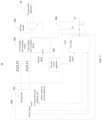
FIG. 1 is a schematic structural diagram of a shutoff control system for a compression apparatus provided by some embodiments of this disclosure. -
FIG. 2 is a schematic structural diagram of a shutoff control system for a compression apparatus provided by some embodiments of this disclosure. -
FIG. 3 is a schematic structural diagram of a shutoff control system for a compression apparatus provided by some embodiments of this disclosure. -
FIG. 4 is a schematic structural diagram of a shutoff control system for a compression apparatus provided by some embodiments of this disclosure. -
FIG. 5 is a schematic structural diagram of a shutoff control system for a compression apparatus provided by some embodiments of this disclosure. -
FIG. 6 is a schematic structural diagram of a shutoff control system for a compression apparatus provided by some embodiments of this disclosure. -
FIG. 7 is a schematic structural diagram of a heat-pump apparatus provided by some embodiments of this disclosure. -
FIG. 8 is a schematic diagram of an electrical device provided by some embodiments of this disclosure. -
FIG. 9 is a schematic diagram of a driving system provided by some embodiments of this disclosure. - By the above-mentioned drawings, specific embodiments of this disclosure have been shown and will be described in more detail hereinafter. These drawings and written description are not intended to limit the scope of the concept of this disclosure in any way, but to illustrate the concept of this disclosure for those skilled in the art by referring to specific embodiments.
- The exemplary embodiments will be illustrated in detail, examples of which are shown in the accompanying drawings. When the following description refers to the accompanying drawings, the same number in different drawings refers to the same or similar elements unless otherwise indicated. The implementations described in the following exemplary examples do not represent all implementations consistent with this disclosure. Rather, they are merely examples of devices and methods consistent with some aspects of this disclosure as recited in the appended claims.
- In the description of this disclosure, it should be understood that the terms "first" and "second" are used for description purposes only, and cannot be interpreted as indicating or implying relative importance or implicitly indicating the number of indicated technical features. Thus, features defined with "first" and "second" may explicitly or implicitly include one or more of these features. In the description of this disclosure, "plurality" means two or more, unless otherwise specifically defined.
- The compression apparatus (including a compressor and a pressure vessel, where a pressure in the pressure vessel changes when the compressor works) is an important part of an air conditioning system and a heat-pump system. In a system containing the compression apparatus, when the system has a high pressure, the pressure in the system will increase continuously if no action is taken to shut off the compression apparatus, resulting in the occurrence of dangers.
- The existing way to shut off the compression apparatus is collecting, by a main control board, a switch signal of the compression apparatus, then outputting, by the main control board, a signal to a module board according to the switch signal, and controlling, by the module board, the compression apparatus to shut off. This way of shutting off the compression apparatus involves many components and has a slow response speed, and the compression apparatus cannot be shut off as long as any one of the components is damaged, resulting in serious consequences. Therefore, how to improve the efficiency and success rate of shutting off the compression apparatus and to improve the safety factor of the air conditioning system and the heat-pump system are still need to be solved.
- Based on this, this disclosure provides a shutoff control system for a compression apparatus, a heat-pump apparatus, a device and a driving system. The shutoff control system for the compression apparatus includes a pressure switch apparatus, a driving apparatus, and a control apparatus. The pressure switch apparatus is configured to be shut off when the pressure switch apparatus detects a pressure of a system to be overpressured, and output a shutoff signal. The driving apparatus is connected to the compression apparatus (the compression apparatus is a compressor), and the driving apparatus, after receiving a first driving signal, outputs a second driving signal to the compression apparatus, and the second driving signal is configured to drive the compression apparatus to work. The control apparatus (such as a logic chip) is connected with the driving apparatus and the pressure switch apparatus for outputting the first driving signal to the driving apparatus, and stopping outputting the first driving signal after the control apparatus receives the shutoff signal. By this way, when the system is overpressured, the control apparatus of the driving apparatus of the compressor stops outputting the driving signal, so that the driving apparatus no longer drives the compressor to work, thereby achieving the purpose of shutting off the compression apparatus. The shutoff control system for the compression apparatus provided by this disclosure involves fewer components, and the compression apparatus is mechanically driven rather than program-driven when the compression apparatus is shut off, thereby improving the efficiency and success rate of shutting off the compression apparatus and improving the safety factor of the air conditioning system and the heat-pump system.
- Referring to
FIG. 1 , an embodiment of this disclosure provides ashutoff control system 10 for a compression apparatus, theshutoff control system 10 is configured to control the shutoff of the compression apparatus 20 (i.e. a compressor), especially to control the shutoff of thecompression apparatus 20 when a system is overpressured, that is, thecompression apparatus 20 is controlled to be shut off when the system is overpressured. The pressure of the system may be a pressure of a part of the system, for example, the pressure of the system refers to the pressure of some components connected to the compressor in an air conditioner. When the system is overpressured, thecompression apparatus 20 is controlled to be shut off, thereby preventing a dangerous situation of continuous rise in pressure caused by thecompression apparatus 20. - The
shutoff control system 10 for the compression apparatus comprises apressure switch apparatus 100, and acontrol apparatus 300 connected to adriving apparatus 200 of thecompression apparatus 20. The drivingapparatus 200 is connected to thecompression apparatus 20, and thedriving apparatus 200 can be understood as a compressor driving module. The drivingapparatus 200 is configured to, after receiving a first driving signal, output a second driving signal to thecompression apparatus 20, and the second driving signal is configured to drive thecompression apparatus 20 to work. If there is no first driving signal, the drivingapparatus 200 will not output the second driving signal, and thus will not drive thecompression apparatus 20 to work. - The
pressure switch apparatus 100 is configured to be shut off when the pressure switch apparatus detects that the system is overpressured, and output a shutoff signal. Thepressure switch apparatus 100 is, for example, a switch portion in a device for detecting whether the system is overpressured. When the system is not overpressured, that is, when the system is running normally, thepressure switch apparatus 100 is in a normally closed state. When the system is detected to be overpressured, thepressure switch apparatus 100 is shut off under an overpressure impact. In an optional embodiment, when the system is not overpressured, that is, when the system is running normally, thepressure switch apparatus 100 is in a normally open state, and when the system is detected to be overpressured, thepressure switch apparatus 100 is closed under an overpressure impact. Therefore, thepressure switch apparatus 100 needs, when the system is overpressured, to be in a state opposite to the state thereof when the system is in a normal operation, so that the shutoff signal can be output to make other apparatuses obtain information about the system is overpressured. - The
control apparatus 300 is connected to thedriving apparatus 200 and thepressure switch apparatus 100. Thecontrol apparatus 300 is configured to output the first driving signal to thedriving apparatus 200, and stop outputting the first driving signal after thecontrol apparatus 300 receives the shutoff signal. As described above, the first driving signal is configured to instruct thedriving apparatus 200 to drive thecompression apparatus 20 to work, and after thecontrol apparatus 300 stops outputting the first driving signal, the drivingapparatus 200 stops outputting the second driving signal to thecompression apparatus 20, thereby achieving the purpose of shutting off thecompression apparatus 20. - The
control apparatus 300 is, for example, a logic chip, and mechanically triggers the stop of outputting the first driving signal after thecontrol apparatus 300 receives the shutoff signal. - To sum up, this example provides the
shutoff control system 10 for the compression apparatus, including thepressure switch apparatus 100 and thecontrol apparatus 300. Thepressure switch apparatus 100 is configured to be shut off when thepressure switch apparatus 100 detects that the system is overpressured, and output the shutoff signal. Thecontrol apparatus 300 is in signal connection with the drivingapparatus 200 and thepressure switch apparatus 100, and is configured to output the first driving signal to thedriving apparatus 200, and is also configured to stop outputting the first driving signal after thecontrol apparatus 300 receives the shutoff signal. The first driving signal is configured to drive the driving apparatus to work. Therefore, when the system is overpressured, thecontrol apparatus 300 controls the drivingapparatus 200 of thecompression apparatus 20 to stop outputting the driving signal, thereby controlling thecompression apparatus 20 to shut off. Under the situation of overpressure protection, there is no need to make software logic judgment, and the hardware is directly driven by signal driving to shut off, therefore, fewer components are required, the response is faster and safer, thereby improving the efficiency and success rate of shutting off thecompression apparatus 20, and improving the safety factor of the air conditioning system and the heat-pump system. - In addition, when the system recovers normal operation, the
control apparatus 300 firstly outputs the first driving signal to thedriving apparatus 200, and then the drivingapparatus 200, under the action of the first driving signal, outputs the second driving signal to thecompression apparatus 20. By this way, when the system suddenly recovers normal operation, the process that thecompression apparatus 20 recovers normal operation has a time buffer, which can prevent a sudden damage of thecompression apparatus 20 caused by the system's sudden recovery to normal operation. - Referring to
FIG. 2 andFIG. 3 , theshutoff control system 10 for the compression apparatus provided by an embodiment of this disclosure further includes a signaloutput control apparatus 400, and the signaloutput control apparatus 400 is connected with thepressure switch apparatus 100 and thecontrol apparatus 300. The signaloutput control apparatus 400 is configured to control thecontrol apparatus 300 to stop outputting the first driving signal according to the shutoff signal. - The signal
output control apparatus 400 includes, for example, a single-chip microcontroller unit (MCU for short) that drives thecontrol apparatus 300, and the MCU, after receiving the shutoff signal, stops outputting a driving signal to thecontrol apparatus 300, thereby controlling thecontrol apparatus 300 to stop outputting the first driving signal. - In an optional embodiment, the signal
output control apparatus 400 includes afirst chip 410 and asecond chip 420. - The
first chip 410 is connected to thepressure switch apparatus 100, and thefirst chip 410 is configured to output a reset signal to thesecond chip 420 according to the shutoff signal. Thesecond chip 420 is in signal connection with thecontrol apparatus 300, and thesecond chip 420 is configured to control thecontrol apparatus 300 to stop outputting the first driving signal according to the reset signal. Thesecond chip 420 is further configured to output a driving signal to drive thecontrol apparatus 300. - The purpose for the
first chip 410 to output the reset signal to thesecond chip 420 is to prevent the situation in which thecontrol apparatus 300, after receiving the shutoff signal, does not stop outputting the first driving signal, and thecontrol apparatus 300 is controlled to stop outputting the first driving signal through thesecond chip 420. - Specifically, when the
first chip 410 is specifically configured to obtain the shutoff signal, thefirst chip 410 also obtains an output signal of thecontrol apparatus 300. When the obtained output signal of thecontrol apparatus 300 is the first driving signal, thefirst chip 410 outputs the reset signal to thesecond chip 420, and thesecond chip 420, after receiving the reset signal, stops outputting the driving signal to thecontrol apparatus 300. More specifically, when thefirst chip 410 determines that the output signal of thecontrol apparatus 300 is the first driving signal, thefirst chip 410 outputs a signal for indicating the control apparatus is in fault to thesecond chip 420 through a pin. - The
second chip 420 is provided with a pin for receiving the reset signal, and thefirst chip 410 sends, by the pin for outputting the reset signal, the reset signal to the pin (RESET, RST) for receiving the reset signal on thesecond chip 420. - In an optional embodiment, the
second chip 420 is further provided with a reset feedback pin, and thefirst chip 410 is further provided with a pin for receiving a feedback signal. Thesecond chip 420 is configured to send the reset feedback signal to thefirst chip 410 through the reset feedback pin after thesecond chip 420 receives the reset signal. The reset feedback signal is configured to indicate that thesecond chip 420 has successfully received the reset signal, so thefirst chip 410 knows that thesecond chip 420 stops outputting the driving signal after thesecond chip 420 receives the reset feedback signal. - Referring to
FIG. 3 , in an optional embodiment, theshutoff control system 10 for the compression apparatus further includes asignal transmission circuit 500, and one end of thesignal transmission circuit 500 is connected to an output end of thecontrol apparatus 300, and is configured to obtain the output signal of thecontrol apparatus 300. The other end of thesignal transmission circuit 500 is connected to an input end of thefirst chip 410. Thesignal transmission circuit 500 is configured to transmit the output signal of thecontrol apparatus 300 to thefirst chip 410. - As shown in
FIG. 3 , thesignal transmission circuit 500 includes a resistor R1 and a capacitor C1. One end of the resistor R1 is connected to the output end of thecontrol apparatus 300, and the other end of the resistor R is connected to the input end of thefirst chip 410 and to one end of the capacitor C1. The one end of the capacitor C1 is further connected to the input end of thefirst chip 410, and the other end of the capacitor C1 is grounded. In addition to the function of signal transmission, thesignal transmission circuit 500 can further perform a stabilizing treatment on the output signal of thecontrol apparatus 300, that is, to make the output signal of thecontrol apparatus 300 more stable. - To sum up, the
shutoff control system 10 for the compression apparatus provided in this embodiment further includes the signaloutput control apparatus 400, and the signaloutput control apparatus 400 includes thefirst chip 410 and thesecond chip 420. Thefirst chip 410 is configured to output the reset signal to thesecond chip 420 according to the shutoff signal, and thesecond chip 420 is configured to control thecontrol apparatus 300 to stop outputting the first driving signal according to the reset signal. By this way, if thecontrol apparatus 300, after receiving the shutoff signal, does not stop outputting the first driving signal, the signaloutput control apparatus 400 can further control thecontrol apparatus 300 to stop outputting the first driving signal, thereby improving the success rate of shutting off thecompression apparatus 20. - Referring to
FIG. 4 , an embodiment of this disclosure provides an example of apressure switch apparatus 100. - The
pressure switch apparatus 100 includes anisolator 110 and apressure switch 120. An enable pin of thecontrol apparatus 300 is further connected to afirst power supply 21, thefirst power supply 21 is, for example, a power supply self-contained in thecompression apparatus 20, and thefirst power supply 21 has an output voltage of, for example, 5V. - A first end of the
isolator 110 is connected to thecontrol apparatus 300 and thefirst power source 21, and a second end of theisolator 110 is grounded. One end of thepressure switch 120 is connected to a third end of theisolator 110 and the other end of thepressure switch 120 is grounded, and thepressure switch 120 is configured to be shut off when the pressure of the system is detected to be overpressured. Theisolator 110 is, for example, an optocoupler isolator. - Specifically, when the
pressure switch 120 is closed, the third end of theisolator 110 is grounded, theisolator 110 is turned on, theisolator 110 and the enable pin of thecontrol apparatus 300 are grounded, and there will be no pressure signal on the enable pin of thecontrol apparatus 300. When thepressure switch 120 is shut off, theisolator 110 is also in a state of not being turned on, so the enable pin of thecontrol apparatus 300 receives a voltage signal outputted from thefirst power supply 21 as the shutoff signal of thepressure switch 120. - In an optional embodiment, the
isolator 110 has a fourth end further connected to asecond power supply 22, and a first pin and a second pin that are connected to thefirst chip 410. Referring toFIG. 4 , when thepressure switch 120 is closed, there is no signal input to the first pin and the second pin of thefirst chip 410, at this time thefirst chip 410 will not receive the shutoff signal. When thepressure switch 120 is shut off, the voltage signal outputted by thesecond power supply 22 cannot pass through theisolator 110, but is transmitted to the first pin and the second pin of thefirst chip 410 through lines. The pressure signal received by thefirst chip 410 through the first pin and the second pin is the shutoff signal. - To sum up, this embodiment exemplarily describes the
pressure switch apparatus 100, thepressure switch apparatus 100 includes theisolator 110 and thepressure switch 120. When the system is detected to be overpressured, thepressure switch 120 is firstly shut off, thereby causing that theisolator 110 cannot be turned on. When theisolator 110 cannot be turned on, thefirst power supply 21 connected to theisolator 110 outputs the pressure signal to the enable pin of thecontrol apparatus 300, so that thecontrol apparatus 300 receives the shutoff signal to stop outputting the first driving signal. - Referring to
FIG. 4 , in an optional embodiment, a resistor R2 and a resistor R3 are further provided between thefirst power supply 21 and the enable pin of thecontrol apparatus 300. One end of the resistor R2 is connected to thefirst power supply 21, and the other end of the resistor R2 is connected to one end of the resistor R3. The other end of the resistor R3 is connected to the enable pin of thecontrol apparatus 300. The resistor R2 and the resistor R3 can make the output voltage from thefirst power supply 21 more stable. - A resistor R4 is further provided between the
pressure switch 120 and theisolator 110, one end of the resistor R4 is connected to the third end of theisolator 110, and the other end of the resistor R4 is connected to one end of thepressure switch 120, and the other end of thepressure switch 120 is grounded. The resistor R4 can make the output voltage from theisolator 110 more stable. - A resistor can further be provided between the
second power supply 22 and theisolator 110, one end of the resistor is connected to thesecond power supply 22, and the other end of the resistor is connected to theisolator 110. - A resistor R5 is disposed between the
second power supply 22 and the first pin of thefirst chip 410, that is, one end of the resistor R5 is connected to thesecond power supply 22 and the other end of the resistor R5 is connected to the first pin of thefirst chip 410. A resistor R6 is disposed between thesecond power supply 22 and the second pin of thefirst chip 410, one end of the resistor R6 is connected to thesecond power supply 22, and the other end of the resistor R6 is connected to the second pin of thefirst chip 410. The resistor R5 and the resistor R6 have a function of stabilizing the voltage signal outputted from thesecond power supply 22. - Referring to
FIG. 5 , in theshutoff control system 10 for the compression apparatus provided by an embodiment of this disclosure, thecontrol apparatus 300 includes N bridge arm pulse width modulation (PWM for short)circuits 310. The number of N is determined by the requirements of the drivingapparatus 200. As shown inFIG. 5 , thecontrol apparatus 300 includes two bridgearm PWM circuits 310, that is, an upper bridge arm 3-channel PWM circuit 310 and a lower bridge arm 3-channel PWM circuit 310. Each bridgearm PWM circuit 310 includes a triode, and thecontrol apparatus 300 includes a triode array. - The N bridge
arm PWM circuits 310 are all driven and turned on by a driving signal outputted by thesecond chip 420. In order to prevent the bridgearm PWM circuits 310 from interacting with each other, each bridgearm PWM circuit 310 of the N bridgearm PWM circuits 310 has different turn-on time. The driving signal outputted by thesecond chip 420 is a pulse signal, and the first driving signal outputted by thecontrol apparatus 300 is also a pulse signal. Optionally, thecontrol apparatus 300 may be an 8-channel buffer. - In an optional embodiment, the
shutoff control system 10 for the compression apparatus further includes a firstprotective apparatus 600 and a secondprotective apparatus 700. One end of the firstprotective apparatus 600 and one end of the secondprotective apparatus 700 are both connected to thedriving apparatus 200, and the other end of the firstprotective apparatus 600 and the other end of the secondprotective apparatus 700 are both connected to thecontrol apparatus 300. Both the firstprotective apparatus 600 and the secondprotective apparatus 700 are configured to buffer the output of thecontrol apparatus 300. - Optionally, the first
protective apparatus 600 includes a first resistor R7 and a first capacitor C2. One end of the first resistor R7 is connected to one bridge arm PWM circuit 310 (such as the upper bridge arm 3-channel PWM circuit 310 shown inFIG. 5 ), and the other end of the first resistor R7 is connected to thedriving apparatus 200. One end of the first capacitor C2 is connected to the other end of the first resistor R7, and the other end of the first capacitor C2 is grounded. The first resistor R7 and the first capacitor C2 can stabilize and buffer the first driving signal outputted by the upper bridge arm 3-channel PWM circuit 310. - Optionally, the second
protective apparatus 700 includes a second resistor R8, a third resistor R9 and a second capacitor C3. One end of the second resistor R8 is connected to one bridge arm PWM circuit 310 (such as the lower bridge arm 3-channel PWM circuit 310 shown inFIG. 5 ), and the other end of the second resistor R8 is connected to thedriving apparatus 200. One end of the third resistor R9 is connected to the one end of the second resistor R8, and the other end of the second resistor R8 is grounded. One end of the second capacitor C3 is connected to the other end of the second resistor R8, and the other end of the second capacitor C3 is grounded. - The second resistor R8, the third resistor R9, and the second capacitor C3 can stabilize and buffer the first driving signal outputted by the lower bridge arm 3-
channel PWM circuit 310. - The resistance values of the first resistor R7, the second resistor R8, and the third resistor R9 can be selected according to actual requirements, and are not limited in this embodiment.
- The specifications of the first capacitor C2 and the second capacitor C3 can be selected according to actual requirements, and are not limited in this embodiment.
- To sum up, when the system is overpressured, the
shutoff control system 10 for the compression apparatus provided by the above embodiment of this disclosure make thecontrol apparatus 300 control the drivingapparatus 200 of thecompression apparatus 20 to stop outputting the driving signal, thereby controlling thecompression apparatus 20 to shut off. Under the situation of overpressure protection, there is no need to make software logic judgment, and the hardware is directly driven to be shut off through signal driving, therefore, fewer components are needed, the response is faster and safer, thereby improving the efficiency and success rate of shutting off thecompression apparatus 20, and improving the safety factor of the air conditioning system and the heat-pump system. - It should further be noted that the types of the power supplies in the
shutoff control system 10 provided in the above embodiments of this disclosure is not limited, and may also be unidirectional power supplies. - Referring to
FIG. 6 , theshutoff control system 10 for the compression apparatus provided by an embodiment of this disclosure further includes the drivingapparatus 200. The drivingapparatus 200 when in use is connected to thecompression apparatus 20 for receiving the first driving signal and then outputting the second driving signal to the compression apparatus, and the second driving signal is configured to drive the compression apparatus to work. The specification and model of the drivingapparatus 200 can be selected according to actual requirements, and is not limited in this embodiment. The number of thePWM circuits 310 in thecontrol apparatus 300 is determined by the drivingapparatus 200. - Referring to
FIG. 7 , an embodiment of this disclosure further provides a heat-pump apparatus 30, the heat-pump apparatus includes theshutoff protection system 10 provided in any one of the above embodiment, and further includes thecompression apparatus 20 and aheat exchange device 31. Theheat exchange device 31 is configured to heat liquid water. The heat-pump apparatus 30 is, for example, a heat-pump swimming-pool machine. The heat-pump swimming-pool machine is generally installed beside a swimming pool for heating the water in the swimming pool. Thecompression apparatus 20 can be disposed inside theheating device 31 or outside theheating device 31. - Referring to
FIG. 8 , an embodiment of this disclosure further provides anelectrical device 40, and theelectrical device 40 includes the heat-pump apparatus 30 provided in any one of the above embodiments, and may further include other apparatuses, which are not limited in this embodiment. - Referring to
FIG. 9 , an embodiment of this disclosure further provides a drivingsystem 50, and the drivingsystem 50 includes theshutoff control system 10 for the compression apparatus provided in any one of the above embodiments, and further includes the drivingapparatus 200. The drivingapparatus 200 when in use is connected to thecompression apparatus 20 for receiving the first driving signal and then outputting the second driving signal to thecompression apparatus 20, and the second driving signal is configured to drive the compression apparatus to work. The description of the drivingapparatus 200 may be referred to the description of the drivingapparatus 200 of theshutoff control system 10 for the compression apparatus provided in the above embodiments, which will not be repeated here. - It should be noted that, in this specification, the terms "comprising", "including" or any other variants thereof are intended to cover non-exclusive inclusion, such that a process, method, article or device including a set of elements not only includes those elements, but also further includes other elements that are not expressly listed or elements inherent in the process, method, article, or device. Without further limitation, an element defined by the statement "includes a... "does not exclude the presence of additional identical elements in the process, method, article, or device that includes the element.
- The order of the above embodiments of this disclosure is for description only, and does not represent the advantages and disadvantages of the embodiments.
| Off control system of | 10 |
| | 100 |
| | 110 |
| | 120 |
| | 200 |
| | 300 |
| Bridge | 310 |
| Signal | 400 |
| | 410 |
| | 420 |
| | 500 |
| First | 600 |
| Second | 700 |
| | 20 |
| | 21 |
| | 22 |
| Heat- | 30 |
| | 31 |
| | 40 |
| | 50 |
Claims (15)
- A shutoff control system for a compression apparatus (10), comprising:a pressure switch apparatus (100), configured to be shut off when a pressure of a system is detected to be overpressured, and output an shutoff signal;a control apparatus (300), connected to the pressure switch apparatus (100), and connected to a driving apparatus (200) of the compression apparatus (20) when the control apparatus (300) is in use; wherein the control apparatus (300) is configured to output a first driving signal to the driving apparatus (200), and stop outputting the first driving signal after the control apparatus (300) receives the shutoff signal; and the first driving signal is configured to instruct the driving apparatus (200) to drive the compression apparatus (20) to work.
- The shutoff control system for the compression apparatus (10) according to claim 1, further comprising:
a signal output control apparatus (400), connected with the pressure switch apparatus (100) and the control apparatus (300), and configured to control the control apparatus (300) to stop outputting the first driving signal according to the shutoff signal. - The shutoff control system for the compression apparatus (10) according to claim 2, wherein the signal output control apparatus (400) comprises a first chip (410) and a second chip (420);the first chip (410) is connected to the pressure switch apparatus (100), and the first chip (410) is configured to output a reset signal to the second chip (420) according to the shutoff signal;the second chip (420) is in signal connection with the control apparatus (300), and the second chip (420) is configured to control the control apparatus (300) to stop outputting the first driving signal according to the reset signal.
- The shutoff control system for the compression apparatus (10) according to claim 3, wherein the first chip (410) is specifically configured to:obtain an output signal of the control apparatus (300) when the first chip (410) obtains the shutoff signal;output the reset signal to the second chip (420) when the output signal of the control apparatus (300) is the first driving signal.
- The shutoff control system for the compression apparatus (10) according to claim 4, further comprising:
a signal transmission circuit (500), with one end connected to an output end of the control apparatus (300) for obtaining the output signal, and the other end connected to an input end of the first chip (410). - The shutoff control system for the compression apparatus (10) according to claim 3, wherein an enable pin of the control apparatus (300) is further connected to a first power supply (21), and the pressure switch apparatus (100) comprises:an isolator (110), with a first end connected to the control apparatus (300) and the first power supply (21), and a second end grounded;a pressure switch (120), with one end connected to a third end of the isolator (110), and the other end grounded, and configured to be shut off when the pressure of the system is detected to be overpressured; andwhen the pressure switch (120) is turned on, the isolator (110) and the enable pin of the control apparatus (300) are grounded;when the pressure switch (120) is turned off, the enable pin of the control apparatus (300) receives a voltage signal output by the first power supply (21) as the shutoff signal.
- The shutoff control system for the compression apparatus (10) according to claim 6, wherein a fourth end of the isolator (110) is further connected to a second power supply (22), and a first pin of the first chip (410) and a second pin of the first chip (410);when the pressure switch (120) is turned on, no signal is inputted to the first pin of the first chip (410) and the second pin of the first chip (410); andwhen the pressure switch (120) is turned off, a pressure signal received by the first chip (410) through the first pin and the second pin is the shutoff signal,or, wherein the isolator (110) is an optocoupler isolator.
- The shutoff control system for the compression apparatus (10) according to claim 3, wherein the first chip (410) comprises a reset feedback pin, and the second chip (420) is configured to send a reset feedback signal to the reset feedback pin after the second chip (420) receives the reset signal, and the reset feedback signal is configured to indicate that the second chip (420) has successfully received the reset signal.
- The shutoff control system for the compression apparatus (10) according to claim 1, wherein the control apparatus (300) comprises N bridge arm pulse width modulation PWM circuits, and each bridge arm PWM circuit (310) of the N bridge arm PWM circuits (310) has different turn-on time; N is an integer greater than 1.
- The shutoff control system for the compression apparatus (10) according to claim 9, wherein each bridge arm PWM circuit (310) comprises a triode.
- The shutoff control system for the compression apparatus (10) according to claim 9, further comprising a first protective apparatus (600) and a second protective apparatus (700);one end of the first protective apparatus (600) and one end of the second protective apparatus (700) are both connected to the driving apparatus (200), and the other end of the first protective apparatus (600) and the other end of the second protective apparatus (700) are both connected to the control apparatus (300), and both of the first protective apparatus (600) and the second protective apparatus (700) are configured to buffer an output of the control apparatus (300),optionally, wherein the first protective apparatus (600) comprises:a first resistor (R7), with one end connected to one bridge arm PWM circuit (310), and the other end connected to the driving apparatus (200); anda first capacitor (C2), with one end connected to the other end of the first resistor (R7), and the other end grounded, or, wherein the second protective apparatus (700) comprises:a second resistor (R8), with one end connected to one bridge arm PWM circuit (310), and the other end connected to the driving apparatus (200);a third resistor (R9), with one end connected to the one end of the second resistor (R8), and the other end grounded; anda second capacitor (C3), with one end connected to the other end of the second resistor (R8), and the other end grounded.
- The shutoff control system for the compression apparatus (10) according to any one of claims 1-11, further comprising:
the driving apparatus (200), connected to the compression apparatus (20) when the driving apparatus (200) is in use, and configured to output a second driving signal to the compression apparatus (20) after the driving apparatus (200) receives the first driving signal, and the second driving signal is configured to drive the compression apparatus (20) to work. - A heat-pump apparatus (30), comprising the shutoff control system for the compression apparatus (10) according to any one of claims 1-12, and further comprising:the compression apparatus (20);a heat exchange device (31), configured to perform heat treatment on liquid water.
- An electrical device (40), comprising the heat-pump apparatus (30) according to claim 13.
- A driving system (50), comprising the shutoff control system for the compression apparatus (10) according to any one of claims 1-12, and further comprising:
the driving apparatus (200), connected to the compression apparatus (20) when the driving apparatus (200) is in use, and configured to output the second driving signal to the compression apparatus (20) after the driving apparatus (200) receives the first driving signal; the second driving signal is configured to drive the compression apparatus (20) to work.
Applications Claiming Priority (1)
| Application Number | Priority Date | Filing Date | Title |
|---|---|---|---|
| CN202210944275.5A CN115288990B (en) | 2022-08-05 | 2022-08-05 | Shut-off control system for compression device, heat pump device, apparatus and drive system |
Publications (2)
| Publication Number | Publication Date |
|---|---|
| EP4317686A1 true EP4317686A1 (en) | 2024-02-07 |
| EP4317686B1 EP4317686B1 (en) | 2025-07-30 |
Family
ID=83829035
Family Applications (1)
| Application Number | Title | Priority Date | Filing Date |
|---|---|---|---|
| EP23190017.6A Active EP4317686B1 (en) | 2022-08-05 | 2023-08-07 | Shutoff control system for compression apparatus, heat-pump apparatus, device and driving system |
Country Status (2)
| Country | Link |
|---|---|
| EP (1) | EP4317686B1 (en) |
| CN (1) | CN115288990B (en) |
Families Citing this family (1)
| Publication number | Priority date | Publication date | Assignee | Title |
|---|---|---|---|---|
| CN115076083B (en) * | 2022-08-05 | 2025-05-30 | 合肥美的暖通设备有限公司 | Shutdown protection, drive and overvoltage shutdown systems, heat pump devices and electrical equipment |
Citations (3)
| Publication number | Priority date | Publication date | Assignee | Title |
|---|---|---|---|---|
| US20170037842A1 (en) * | 2015-08-07 | 2017-02-09 | Max Co., Ltd. | Air compressor |
| EP3450882A1 (en) * | 2017-08-29 | 2019-03-06 | LG Electronics Inc. | Circuit for blocking operation of compressor |
| KR20190072893A (en) * | 2017-12-18 | 2019-06-26 | 엘지전자 주식회사 | Air conditioner having function of protecting compressor |
Family Cites Families (9)
| Publication number | Priority date | Publication date | Assignee | Title |
|---|---|---|---|---|
| US5120199A (en) * | 1991-06-28 | 1992-06-09 | Abbott Laboratories | Control system for valveless metering pump |
| KR101219130B1 (en) * | 2010-05-25 | 2013-01-07 | 화남전자 주식회사 | Control system and method for preventing over-pressure of air compressor of vehicle |
| KR101190069B1 (en) * | 2011-05-23 | 2012-10-12 | 엘지전자 주식회사 | Apparatus for controlling compressor |
| US10823444B2 (en) * | 2017-03-31 | 2020-11-03 | Johnson Controls Technology Company | Pressure control device |
| IT201700043015A1 (en) * | 2017-04-19 | 2018-10-19 | Abac Aria Compressa | Compressor equipped with electronic pressure switch and procedure for regulating the pressure in such a compressor. |
| CN110848125B (en) * | 2019-12-02 | 2021-04-27 | 广东美的暖通设备有限公司 | Control circuit, air conditioner and control method |
| CN111005862B (en) * | 2019-12-16 | 2022-02-15 | 广东美的暖通设备有限公司 | Pressure protection circuit, control method, and computer-readable storage medium |
| CN111474868A (en) * | 2020-03-17 | 2020-07-31 | 温氏食品集团股份有限公司 | Switch detection circuit, manure scraping control device, method, device and manure scraping system |
| CN115076083B (en) * | 2022-08-05 | 2025-05-30 | 合肥美的暖通设备有限公司 | Shutdown protection, drive and overvoltage shutdown systems, heat pump devices and electrical equipment |
-
2022
- 2022-08-05 CN CN202210944275.5A patent/CN115288990B/en active Active
-
2023
- 2023-08-07 EP EP23190017.6A patent/EP4317686B1/en active Active
Patent Citations (3)
| Publication number | Priority date | Publication date | Assignee | Title |
|---|---|---|---|---|
| US20170037842A1 (en) * | 2015-08-07 | 2017-02-09 | Max Co., Ltd. | Air compressor |
| EP3450882A1 (en) * | 2017-08-29 | 2019-03-06 | LG Electronics Inc. | Circuit for blocking operation of compressor |
| KR20190072893A (en) * | 2017-12-18 | 2019-06-26 | 엘지전자 주식회사 | Air conditioner having function of protecting compressor |
Also Published As
| Publication number | Publication date |
|---|---|
| EP4317686B1 (en) | 2025-07-30 |
| CN115288990A (en) | 2022-11-04 |
| CN115288990B (en) | 2025-07-22 |
Similar Documents
| Publication | Publication Date | Title |
|---|---|---|
| EP4317686B1 (en) | Shutoff control system for compression apparatus, heat-pump apparatus, device and driving system | |
| EP3352357A1 (en) | Fault protection method and device for sub-modules of modular multilevel converter | |
| CN101197532A (en) | Freezing device and inverter device for freezing device | |
| CN104141623A (en) | Fan speed control system | |
| CN112594875B (en) | Method for controlling number of communication units of multi-online indoor unit | |
| CN104660440A (en) | Blade server management system and control method thereof | |
| CN107084514B (en) | Device for air conditioning system pressure protection and air conditioning system | |
| EP4317687B1 (en) | Turn-off protection, driving and overpressure turn-off systems, heat pump apparatus, and electrical device | |
| CN204259266U (en) | A kind of digitlization is used for the high voltage source of movable high-frequency X-ray machine | |
| CN107044750B (en) | Drive control method, system and the equipment of electric expansion valve | |
| EP3992551B1 (en) | Control circuit, air conditioner, and control method | |
| US5223821A (en) | Triac power switching and testing system | |
| CN110805542A (en) | Cooling water control method, device and system and computer readable medium | |
| KR101452268B1 (en) | Remote controller for an air preheater | |
| CN203895980U (en) | Marine controlling apparatus | |
| CN1053692A (en) | The static input protection of microprocessor controls | |
| CN221100086U (en) | Remote monitoring system for fan test and air conditioner test system | |
| CN105573357A (en) | Air discharging pressure stabilizer and air discharging pressure stabilizing method | |
| KR101548978B1 (en) | Remote monitoring system of substation device | |
| CN110927610A (en) | Fault diagnosis method and system of inverter power supply voltage detection circuit based on modulated wave | |
| CN104037753A (en) | Control device used for ship | |
| JP2772210B2 (en) | Electronic equipment cooling system | |
| CN216518559U (en) | Control system for hydraulic drive air compressor | |
| DE102004005995B4 (en) | Powered interface card and method for providing a backup power supply | |
| CN208861163U (en) | A kind of device for preventing total station from crashing in automatic monitoring |
Legal Events
| Date | Code | Title | Description |
|---|---|---|---|
| PUAI | Public reference made under article 153(3) epc to a published international application that has entered the european phase |
Free format text: ORIGINAL CODE: 0009012 |
|
| STAA | Information on the status of an ep patent application or granted ep patent |
Free format text: STATUS: REQUEST FOR EXAMINATION WAS MADE |
|
| 17P | Request for examination filed |
Effective date: 20230807 |
|
| AK | Designated contracting states |
Kind code of ref document: A1 Designated state(s): AL AT BE BG CH CY CZ DE DK EE ES FI FR GB GR HR HU IE IS IT LI LT LU LV MC ME MK MT NL NO PL PT RO RS SE SI SK SM TR |
|
| GRAP | Despatch of communication of intention to grant a patent |
Free format text: ORIGINAL CODE: EPIDOSNIGR1 |
|
| STAA | Information on the status of an ep patent application or granted ep patent |
Free format text: STATUS: GRANT OF PATENT IS INTENDED |
|
| GRAS | Grant fee paid |
Free format text: ORIGINAL CODE: EPIDOSNIGR3 |
|
| INTG | Intention to grant announced |
Effective date: 20250522 |
|
| GRAA | (expected) grant |
Free format text: ORIGINAL CODE: 0009210 |
|
| STAA | Information on the status of an ep patent application or granted ep patent |
Free format text: STATUS: THE PATENT HAS BEEN GRANTED |
|
| AK | Designated contracting states |
Kind code of ref document: B1 Designated state(s): AL AT BE BG CH CY CZ DE DK EE ES FI FR GB GR HR HU IE IS IT LI LT LU LV MC ME MK MT NL NO PL PT RO RS SE SI SK SM TR |
|
| REG | Reference to a national code |
Ref country code: GB Ref legal event code: FG4D |
|
| REG | Reference to a national code |
Ref country code: CH Ref legal event code: EP |
|
| REG | Reference to a national code |
Ref country code: DE Ref legal event code: R096 Ref document number: 602023005191 Country of ref document: DE |
|
| REG | Reference to a national code |
Ref country code: IE Ref legal event code: FG4D |
|
| PGFP | Annual fee paid to national office [announced via postgrant information from national office to epo] |
Ref country code: DE Payment date: 20250827 Year of fee payment: 3 |
|
| PGFP | Annual fee paid to national office [announced via postgrant information from national office to epo] |
Ref country code: FR Payment date: 20250826 Year of fee payment: 3 Ref country code: AT Payment date: 20251020 Year of fee payment: 3 |
|
| REG | Reference to a national code |
Ref country code: NL Ref legal event code: MP Effective date: 20250730 |
|
| REG | Reference to a national code |
Ref country code: AT Ref legal event code: MK05 Ref document number: 1819175 Country of ref document: AT Kind code of ref document: T Effective date: 20250730 |
|
| PG25 | Lapsed in a contracting state [announced via postgrant information from national office to epo] |
Ref country code: PT Free format text: LAPSE BECAUSE OF FAILURE TO SUBMIT A TRANSLATION OF THE DESCRIPTION OR TO PAY THE FEE WITHIN THE PRESCRIBED TIME-LIMIT Effective date: 20251202 |
|
| PG25 | Lapsed in a contracting state [announced via postgrant information from national office to epo] |
Ref country code: IS Free format text: LAPSE BECAUSE OF FAILURE TO SUBMIT A TRANSLATION OF THE DESCRIPTION OR TO PAY THE FEE WITHIN THE PRESCRIBED TIME-LIMIT Effective date: 20251130 |
|
| PG25 | Lapsed in a contracting state [announced via postgrant information from national office to epo] |
Ref country code: NO Free format text: LAPSE BECAUSE OF FAILURE TO SUBMIT A TRANSLATION OF THE DESCRIPTION OR TO PAY THE FEE WITHIN THE PRESCRIBED TIME-LIMIT Effective date: 20251030 |
|
| REG | Reference to a national code |
Ref country code: LT Ref legal event code: MG9D |
|
| PG25 | Lapsed in a contracting state [announced via postgrant information from national office to epo] |
Ref country code: AT Free format text: LAPSE BECAUSE OF FAILURE TO SUBMIT A TRANSLATION OF THE DESCRIPTION OR TO PAY THE FEE WITHIN THE PRESCRIBED TIME-LIMIT Effective date: 20250730 |
|
| PG25 | Lapsed in a contracting state [announced via postgrant information from national office to epo] |
Ref country code: FI Free format text: LAPSE BECAUSE OF FAILURE TO SUBMIT A TRANSLATION OF THE DESCRIPTION OR TO PAY THE FEE WITHIN THE PRESCRIBED TIME-LIMIT Effective date: 20250730 |
|
| PG25 | Lapsed in a contracting state [announced via postgrant information from national office to epo] |
Ref country code: HR Free format text: LAPSE BECAUSE OF FAILURE TO SUBMIT A TRANSLATION OF THE DESCRIPTION OR TO PAY THE FEE WITHIN THE PRESCRIBED TIME-LIMIT Effective date: 20250730 Ref country code: NL Free format text: LAPSE BECAUSE OF FAILURE TO SUBMIT A TRANSLATION OF THE DESCRIPTION OR TO PAY THE FEE WITHIN THE PRESCRIBED TIME-LIMIT Effective date: 20250730 |
|
| PG25 | Lapsed in a contracting state [announced via postgrant information from national office to epo] |
Ref country code: GR Free format text: LAPSE BECAUSE OF FAILURE TO SUBMIT A TRANSLATION OF THE DESCRIPTION OR TO PAY THE FEE WITHIN THE PRESCRIBED TIME-LIMIT Effective date: 20251031 |
|
| PG25 | Lapsed in a contracting state [announced via postgrant information from national office to epo] |
Ref country code: SE Free format text: LAPSE BECAUSE OF FAILURE TO SUBMIT A TRANSLATION OF THE DESCRIPTION OR TO PAY THE FEE WITHIN THE PRESCRIBED TIME-LIMIT Effective date: 20250730 |
|
| PG25 | Lapsed in a contracting state [announced via postgrant information from national office to epo] |
Ref country code: LV Free format text: LAPSE BECAUSE OF FAILURE TO SUBMIT A TRANSLATION OF THE DESCRIPTION OR TO PAY THE FEE WITHIN THE PRESCRIBED TIME-LIMIT Effective date: 20250730 |
|
| PG25 | Lapsed in a contracting state [announced via postgrant information from national office to epo] |
Ref country code: BG Free format text: LAPSE BECAUSE OF FAILURE TO SUBMIT A TRANSLATION OF THE DESCRIPTION OR TO PAY THE FEE WITHIN THE PRESCRIBED TIME-LIMIT Effective date: 20250730 Ref country code: PL Free format text: LAPSE BECAUSE OF FAILURE TO SUBMIT A TRANSLATION OF THE DESCRIPTION OR TO PAY THE FEE WITHIN THE PRESCRIBED TIME-LIMIT Effective date: 20250730 |
|
| PG25 | Lapsed in a contracting state [announced via postgrant information from national office to epo] |
Ref country code: RS Free format text: LAPSE BECAUSE OF FAILURE TO SUBMIT A TRANSLATION OF THE DESCRIPTION OR TO PAY THE FEE WITHIN THE PRESCRIBED TIME-LIMIT Effective date: 20251030 |
|
| PG25 | Lapsed in a contracting state [announced via postgrant information from national office to epo] |
Ref country code: ES Free format text: LAPSE BECAUSE OF FAILURE TO SUBMIT A TRANSLATION OF THE DESCRIPTION OR TO PAY THE FEE WITHIN THE PRESCRIBED TIME-LIMIT Effective date: 20250730 |
|
| PG25 | Lapsed in a contracting state [announced via postgrant information from national office to epo] |
Ref country code: RO Free format text: LAPSE BECAUSE OF FAILURE TO SUBMIT A TRANSLATION OF THE DESCRIPTION OR TO PAY THE FEE WITHIN THE PRESCRIBED TIME-LIMIT Effective date: 20250730 |
|
| PG25 | Lapsed in a contracting state [announced via postgrant information from national office to epo] |
Ref country code: SM Free format text: LAPSE BECAUSE OF FAILURE TO SUBMIT A TRANSLATION OF THE DESCRIPTION OR TO PAY THE FEE WITHIN THE PRESCRIBED TIME-LIMIT Effective date: 20250730 |
|
| PG25 | Lapsed in a contracting state [announced via postgrant information from national office to epo] |
Ref country code: DK Free format text: LAPSE BECAUSE OF FAILURE TO SUBMIT A TRANSLATION OF THE DESCRIPTION OR TO PAY THE FEE WITHIN THE PRESCRIBED TIME-LIMIT Effective date: 20250730 |
|
| PG25 | Lapsed in a contracting state [announced via postgrant information from national office to epo] |
Ref country code: LU Free format text: LAPSE BECAUSE OF NON-PAYMENT OF DUE FEES Effective date: 20250807 Ref country code: IT Free format text: LAPSE BECAUSE OF FAILURE TO SUBMIT A TRANSLATION OF THE DESCRIPTION OR TO PAY THE FEE WITHIN THE PRESCRIBED TIME-LIMIT Effective date: 20250730 |
|
| PG25 | Lapsed in a contracting state [announced via postgrant information from national office to epo] |
Ref country code: CZ Free format text: LAPSE BECAUSE OF FAILURE TO SUBMIT A TRANSLATION OF THE DESCRIPTION OR TO PAY THE FEE WITHIN THE PRESCRIBED TIME-LIMIT Effective date: 20250730 |
|
| PG25 | Lapsed in a contracting state [announced via postgrant information from national office to epo] |
Ref country code: SK Free format text: LAPSE BECAUSE OF FAILURE TO SUBMIT A TRANSLATION OF THE DESCRIPTION OR TO PAY THE FEE WITHIN THE PRESCRIBED TIME-LIMIT Effective date: 20250730 Ref country code: EE Free format text: LAPSE BECAUSE OF FAILURE TO SUBMIT A TRANSLATION OF THE DESCRIPTION OR TO PAY THE FEE WITHIN THE PRESCRIBED TIME-LIMIT Effective date: 20250730 |