EP4317675B1 - Luftgefülltes kaplanturbinenlaufrad - Google Patents
Luftgefülltes kaplanturbinenlaufrad Download PDFInfo
- Publication number
- EP4317675B1 EP4317675B1 EP22306182.1A EP22306182A EP4317675B1 EP 4317675 B1 EP4317675 B1 EP 4317675B1 EP 22306182 A EP22306182 A EP 22306182A EP 4317675 B1 EP4317675 B1 EP 4317675B1
- Authority
- EP
- European Patent Office
- Prior art keywords
- flow
- turbine
- air
- dry air
- hub
- Prior art date
- Legal status (The legal status is an assumption and is not a legal conclusion. Google has not performed a legal analysis and makes no representation as to the accuracy of the status listed.)
- Active
Links
Images



Classifications
-
- F—MECHANICAL ENGINEERING; LIGHTING; HEATING; WEAPONS; BLASTING
- F03—MACHINES OR ENGINES FOR LIQUIDS; WIND, SPRING, OR WEIGHT MOTORS; PRODUCING MECHANICAL POWER OR A REACTIVE PROPULSIVE THRUST, NOT OTHERWISE PROVIDED FOR
- F03B—MACHINES OR ENGINES FOR LIQUIDS
- F03B11/00—Parts or details not provided for in, or of interest apart from, the preceding groups, e.g. wear-protection couplings, between turbine and generator
- F03B11/002—Injecting air or other fluid
-
- F—MECHANICAL ENGINEERING; LIGHTING; HEATING; WEAPONS; BLASTING
- F03—MACHINES OR ENGINES FOR LIQUIDS; WIND, SPRING, OR WEIGHT MOTORS; PRODUCING MECHANICAL POWER OR A REACTIVE PROPULSIVE THRUST, NOT OTHERWISE PROVIDED FOR
- F03B—MACHINES OR ENGINES FOR LIQUIDS
- F03B3/00—Machines or engines of reaction type; Parts or details peculiar thereto
- F03B3/04—Machines or engines of reaction type; Parts or details peculiar thereto with substantially axial flow throughout rotors, e.g. propeller turbines
- F03B3/06—Machines or engines of reaction type; Parts or details peculiar thereto with substantially axial flow throughout rotors, e.g. propeller turbines with adjustable blades, e.g. Kaplan turbines
-
- F—MECHANICAL ENGINEERING; LIGHTING; HEATING; WEAPONS; BLASTING
- F03—MACHINES OR ENGINES FOR LIQUIDS; WIND, SPRING, OR WEIGHT MOTORS; PRODUCING MECHANICAL POWER OR A REACTIVE PROPULSIVE THRUST, NOT OTHERWISE PROVIDED FOR
- F03B—MACHINES OR ENGINES FOR LIQUIDS
- F03B3/00—Machines or engines of reaction type; Parts or details peculiar thereto
- F03B3/12—Blades; Blade-carrying rotors
- F03B3/14—Rotors having adjustable blades
-
- F—MECHANICAL ENGINEERING; LIGHTING; HEATING; WEAPONS; BLASTING
- F05—INDEXING SCHEMES RELATING TO ENGINES OR PUMPS IN VARIOUS SUBCLASSES OF CLASSES F01-F04
- F05B—INDEXING SCHEME RELATING TO WIND, SPRING, WEIGHT, INERTIA OR LIKE MOTORS, TO MACHINES OR ENGINES FOR LIQUIDS COVERED BY SUBCLASSES F03B, F03D AND F03G
- F05B2260/00—Function
- F05B2260/60—Fluid transfer
- F05B2260/64—Aeration, ventilation, dehumidification or moisture removal of closed spaces
-
- Y—GENERAL TAGGING OF NEW TECHNOLOGICAL DEVELOPMENTS; GENERAL TAGGING OF CROSS-SECTIONAL TECHNOLOGIES SPANNING OVER SEVERAL SECTIONS OF THE IPC; TECHNICAL SUBJECTS COVERED BY FORMER USPC CROSS-REFERENCE ART COLLECTIONS [XRACs] AND DIGESTS
- Y02—TECHNOLOGIES OR APPLICATIONS FOR MITIGATION OR ADAPTATION AGAINST CLIMATE CHANGE
- Y02E—REDUCTION OF GREENHOUSE GAS [GHG] EMISSIONS, RELATED TO ENERGY GENERATION, TRANSMISSION OR DISTRIBUTION
- Y02E10/00—Energy generation through renewable energy sources
- Y02E10/20—Hydro energy
Definitions
- the invention concerns turbines equipped with Kaplan runners.
- a Kaplan turbine 100 The general structure of a Kaplan turbine 100 is illustrated on figure 1 ; it comprises a runner 112 that is secured at a first end of a rotating shaft 126 centered on a vertical axis Z1 and configured to rotate around said axis in operating conditions. It further comprises a hub 114 equipped with a series of movable or adjustable runner blades 116. Coupling flanges 118 connect each a runner blade 116 to the hub 114, so that the blades are adjustable.
- the runner 112 is housed in the upper part of a draft tube 200 that is designed for evacuating water downstream and for increasing the efficiency of turbine 100.
- a volute 122 is arranged around the runner 112 and is fed with water.
- the volute 122 is usually connected to a non-represented penstock that extends from a non-represented upstream reservoir.
- water outbursts in the volute 122 with a high potential energy.
- Water flows afterwards between the blades 116 of runner 112, thereby inducing the runner 112 to rotate.
- the flow rate of water circulating around the runner 112 is regulated by the blades themselves and also by means of guide vanes 124 that are disposed in a circular pattern within the distributor.
- the guide vanes 124 are each pivotable around an axis parallel to axis Z1 to reduce or increase the flow rate of water entering the turbine 100.
- a generator rotor 132 is connected at a second end of the shaft 126, which is opposed to the first end thereof in the longitudinal direction of the shaft 126, that is along axis Z1.
- the rotor 132 is disposed coaxially within a stator 134 of a generator 130.
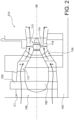
- FIG. 2 Another embodiment, to which the invention also applies, is shown on figure 2 : the shaft is arranged horizontally and the turbine 106 (or bulb turbine) comprises components identical or similar to those of figure 1 and which bear the same reference numbers.
- the blades 116 are attached to the hub 114 and are part of the bulb unit 106.
- the installation of figure 2 further includes a concrete structure 140 that delimits a horizontal channel C1 of circulation of water.
- the bulb 106 is disposed within the channel C1 and is adapted to rotate around a horizontal rotation axis X6 under the action of a forced water flow F coming from a non-represented reservoir.
- the bulb 106 includes a bulb casing 180 that is supported within channel C1 by a bulb hanger 109 and stay vanes 111.
- the runner 112 is coupled to a non-represented generator which is disposed within the bulb casing 180 and which delivers an alternative voltage to a non-represented electricity power grid.
- Kaplan turbine will refer to a turbine provided with a Kaplan runner, whatever the direction of its shaft. Alternatively, it will be referred to a turbine with a Kaplan runner.
- the moving parts of such turbines are usually lubricated with grease or oil .
- Kaplan runner hubs are designed to be filled with oil, but we see more and more environmental pressures requesting oil free runners.
- Oil free runners are known in the art, for example from CA 2889026 : they are designed with self-lubricated bushing operating in a hub filled with water instead of oil. But this design is plagued with limitations and problems. The life expectancy of self-lubricated bushings and blade's mechanisms components of the runner hub in water are much shorter than bronze bushings in oil due to corrosion, even when stainless steel is used.
- a corrosion inhibitor is sometime used to prevent/limit the corrosion inside the runner, but due to environmental constraints this kind of chemical products is less and less accepted and for most of self-lubricated bushings the wear and friction are still negatively impacted by water.
- An air-filled hub can be implemented instead of a water-filled hub, but this type of runner is known to provide a humid environment which is also unfavorable for the life of the runner and prone to heavy detrimental rusting effects. This detrimental effect is even present if the air-filled hub is maintained at a positive pressure, due to condensation and to potential minor water leaks inside the hub.
- the invention first concerns a turbine comprising a shaft, a runner, or a Kaplan runner, which comprises a number of blades and a hub, located at the end of the shaft and supporting the blades, said turbine further comprising :
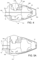
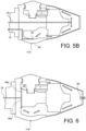
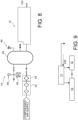
- a hub of a turbine preferably comprising a Kaplan turbine, can be swept with dry air, eliminating at least part of, and preferably all, the water and humidity present in the turbine.
Landscapes
- Engineering & Computer Science (AREA)
- Chemical & Material Sciences (AREA)
- Combustion & Propulsion (AREA)
- Mechanical Engineering (AREA)
- General Engineering & Computer Science (AREA)
- Hydraulic Turbines (AREA)
- Control Of Water Turbines (AREA)
Claims (15)
- Turbine (1), umfassend:- eine Welle (126);- einen Kaplanläufer, der eine Anzahl von Schaufeln (116) und eine Nabe (114) umfasst, die sich am Ende der Welle befinden und die Schaufeln tragen,- Mittel (10) zum Erzeugen von trockener Luft;- Mittel (12, 16) zum Versorgen der Turbine mit einem Trocken (120) trockener Luft;- Mittel (14, 18, 22, 27, 35) zum Absaugen eines Luftstroms (185) aus der Turbine, nachdem der Trockenluftstrom mindestens durch die Nabe (114) geflossen ist.
- Turbine nach Anspruch 1, ferner umfassend Mittel (24) zum Überwachen oder Messen der Luftfeuchtigkeit des aus der Turbine abgesaugten Luftstroms (185).
- Turbine nach einem der Ansprüche 1 bis 2, ferner umfassend eine Auslasskammer oder einen Behälter (22) zum Auffangen mindestens eines Teils des aus der Turbine abgesaugten Luftstroms (185).
- Turbine nach Anspruch 3, wobei die Auslasskammer die Welle (126) mindestens teilweise umgibt.
- Turbine nach einem der Ansprüche 1 bis 4, die Mittel (12, 16) zum Versorgen der Turbine mit einem Strom (120) trockener Luft, umfassend einen Einlasskanal (16) innerhalb der Welle (126).
- Turbine nach einem der Ansprüche 1 bis 5, wobei die Mittel (14, 18, 22, 27, 35) zum Absaugen eines Luftstroms (185) aus der Turbine, nachdem der Trockenluftstrom mindestens durch die Nabe (114) geströmt ist, umfassend einen Auslasskanal (14), der an der Welle (126) befestigt ist oder sich mit ihr dreht oder sich darin befindet.
- Turbine nach einem der Ansprüche 1 bis 5, das Mittel (35) zum Absaugen eines Luftstroms (185) aus der Turbine, nachdem der Trockenluftstrom mindestens durch die Nabe (114) geströmt ist, umfassend einen Auslass (35) zum Absaugen der Luft in einen Wasserstrom.
- Turbine nach einem der Ansprüche 1 bis 7, die Mittel (12, 16) zum Versorgen der Turbine mit einem Strom (120) trockener Luft, umfassend Mittel (17) zum Variieren des Stromes oder der Frequenz des Stromes (120) trockener Luft.
- Turbine nach Anspruch 8, ferner umfassend Mittel (24, 12) zum Regeln der Mittel zum Variieren des Stroms oder der Frequenz des Stroms (120) trockener Luft, beispielsweise auf der Grundlage eines Feuchtigkeitsgrads oder -rate des an der Turbine abgesaugten Stroms (185) von Luft.
- Turbine nach einem der Ansprüche 1 bis 9, wobei die Mittel zum Versorgen der Welle mit trockener Luft einen Behälter (40) zum Speichern von trockener Luft umfasst.
- Turbine nach einem der Ansprüche 1 bis 10, wobei die Mittel zum Versorgen der Welle mit trockener Luft Mittel (44) zum Trocknen der Luft umfasst.
- Verfahren zum Betreiben einer Turbine, umfassend eine Welle (126), einen Kaplanläufer mit einer Anzahl von Schaufeln (116) und einer Nabe (114), die sich am Ende der Welle befinden und die Schaufeln tragen, wobei das Verfahren Folgendes umfasst:- Erzeugen eines Trockenluftstroms (120);- Versorgen der Turbine mit dem Strom (120) der trockenen Luft;- Absaugen eines Stroms (185) trockener Luft aus der Turbine, nachdem der Trockenluftstrom mindestens durch die Nabe (114) geströmt ist.
- Verfahren nach Anspruch 12, ferner umfassend das Messen einer Feuchtigkeitsrate des Stromes (185) trockener Luft, der aus der Turbine abgesaugt wird.
- Verfahren nach Anspruch 13, ferner umfassend das Variieren des Stromes (120) trockener Luft in Abhängigkeit von der Feuchtigkeitsrate.
- Verfahren nach einem der Ansprüche 12 bis 14, wobei der Strom (120) trockener Luft der Turbine durch einen mindestens teilweise in der Welle befindlichen Einlasskanal (16) zugeführt wird und/oder der Luftstrom (185) durch einen an der Welle befestigten oder sich mit ihr drehenden oder mindestens teilweise in der Welle befindlichen Auslasskanal (14) aus der Turbine abgesaugt wird und/oder der Luftstrom durch einen Auslass (35) in einen Wasserstrom abgesaugt wird.
Priority Applications (6)
| Application Number | Priority Date | Filing Date | Title |
|---|---|---|---|
| EP22306182.1A EP4317675B1 (de) | 2022-08-04 | 2022-08-04 | Luftgefülltes kaplanturbinenlaufrad |
| ES22306182T ES3039809T3 (en) | 2022-08-04 | 2022-08-04 | Air-filled kaplan turbine runner |
| PT223061821T PT4317675T (pt) | 2022-08-04 | 2022-08-04 | Rotor de turbina kaplan preenchido com ar |
| CA3263278A CA3263278A1 (en) | 2022-08-04 | 2023-08-03 | KAPLAN TURBINE WHEEL FILLED WITH AIR |
| PCT/EP2023/071513 WO2024028425A1 (en) | 2022-08-04 | 2023-08-03 | Air-filled kaplan runner |
| US19/101,027 US20260049590A1 (en) | 2022-08-04 | 2023-08-03 | Air-filled kaplan runner |
Applications Claiming Priority (1)
| Application Number | Priority Date | Filing Date | Title |
|---|---|---|---|
| EP22306182.1A EP4317675B1 (de) | 2022-08-04 | 2022-08-04 | Luftgefülltes kaplanturbinenlaufrad |
Publications (2)
| Publication Number | Publication Date |
|---|---|
| EP4317675A1 EP4317675A1 (de) | 2024-02-07 |
| EP4317675B1 true EP4317675B1 (de) | 2025-06-25 |
Family
ID=82932564
Family Applications (1)
| Application Number | Title | Priority Date | Filing Date |
|---|---|---|---|
| EP22306182.1A Active EP4317675B1 (de) | 2022-08-04 | 2022-08-04 | Luftgefülltes kaplanturbinenlaufrad |
Country Status (6)
| Country | Link |
|---|---|
| US (1) | US20260049590A1 (de) |
| EP (1) | EP4317675B1 (de) |
| CA (1) | CA3263278A1 (de) |
| ES (1) | ES3039809T3 (de) |
| PT (1) | PT4317675T (de) |
| WO (1) | WO2024028425A1 (de) |
Family Cites Families (7)
| Publication number | Priority date | Publication date | Assignee | Title |
|---|---|---|---|---|
| US1942995A (en) * | 1932-06-21 | 1934-01-09 | James Leffel & Company | Hydraulic turbine |
| FR1017514A (fr) * | 1950-02-10 | 1952-12-11 | Charmilles Sa Ateliers | Perfectionnements apportés aux turbomachines hydrauliques |
| FR1164867A (fr) * | 1956-02-20 | 1958-10-15 | Charmilles Sa Ateliers | Turbine hydraulique |
| GB986797A (en) * | 1960-04-09 | 1965-03-24 | Hussein Haekal | Improvements in and relating to machines comprising a bladed rotor such as water turbines and pumps |
| US3305215A (en) * | 1966-04-05 | 1967-02-21 | Allis Chalmers Mfg Co | Fluid cushion for hydraulic turbomachinery |
| DE102011085950A1 (de) * | 2011-11-08 | 2013-05-08 | Wobben Properties Gmbh | Turbine für eine Wasserkraftanlage und Wasserkraftanlage |
| DE102012022583A1 (de) * | 2012-11-20 | 2014-05-22 | Voith Patent Gmbh | Laufrad einer Kaplanturbine |
-
2022
- 2022-08-04 EP EP22306182.1A patent/EP4317675B1/de active Active
- 2022-08-04 PT PT223061821T patent/PT4317675T/pt unknown
- 2022-08-04 ES ES22306182T patent/ES3039809T3/es active Active
-
2023
- 2023-08-03 WO PCT/EP2023/071513 patent/WO2024028425A1/en not_active Ceased
- 2023-08-03 CA CA3263278A patent/CA3263278A1/en active Pending
- 2023-08-03 US US19/101,027 patent/US20260049590A1/en active Pending
Also Published As
| Publication number | Publication date |
|---|---|
| ES3039809T3 (en) | 2025-10-24 |
| US20260049590A1 (en) | 2026-02-19 |
| PT4317675T (pt) | 2025-09-22 |
| WO2024028425A1 (en) | 2024-02-08 |
| EP4317675A1 (de) | 2024-02-07 |
| CA3263278A1 (en) | 2024-02-08 |
Similar Documents
| Publication | Publication Date | Title |
|---|---|---|
| CN102252927B (zh) | 高压水射流旋转冲击水蚀实验装置 | |
| EP2646315B1 (de) | Dichtungsanordnung für eine antriebswelle und verfahren zum abdichten einer propellerwelle | |
| CN109882425A (zh) | 轴向力平衡与密封结构及高功率密度离心风机 | |
| CN111919052B (zh) | 具有低摩擦径向轴密封件的风力涡轮机传动系部件 | |
| EP4317675A1 (de) | Luftgefülltes kaplanturbinenlaufrad | |
| CN102062107A (zh) | 一种长轴多级轴向流液下泵和输送光气方法 | |
| WO2019194942A1 (en) | Nitrogen purge of compressor dry seal background | |
| RU2402750C2 (ru) | Стенд для высотно-климатических испытаний турбовинтовых и турбовальных двигателей | |
| CN103629144A (zh) | 立式液下泵轴承保护装置 | |
| JP6259289B2 (ja) | 横軸ポンプ | |
| CN109882424A (zh) | 高功率密度离心风机及离心风机控制系统 | |
| JP6079413B2 (ja) | 立軸水車の軸受装置、及び立軸水車発電機 | |
| CA1138302A (en) | Hydroelectric power station | |
| CN111911416A (zh) | 一种核电厂用二回路应急补水柴油机泵组及系统 | |
| CN108626054B (zh) | 水力机械的可动叶片操作系统 | |
| CN206670918U (zh) | 汽轮机试验装置 | |
| CN203249518U (zh) | 两侧旋转布水间接蒸发冷却器 | |
| CN108194385B (zh) | 两相流流体机械过流部件磨损性能测试装置及测试方法 | |
| JP2015048718A (ja) | 低圧蒸気の再利用装置 | |
| KR101195082B1 (ko) | 소수력 발전장치 | |
| CN217898061U (zh) | 发电机组轴承油槽智能在线监测系统 | |
| CN109779813A (zh) | 一种轴流转桨式水轮发电机组下浮动瓦故障诊断方法 | |
| US20150219064A1 (en) | Blade Wheel of a Kaplan Turbine | |
| CN222501822U (zh) | 一种气幕系统及汽轮机 | |
| CN110735817B (zh) | 用于非能动核电厂核主泵的外置式轴向力平衡装置 |
Legal Events
| Date | Code | Title | Description |
|---|---|---|---|
| PUAI | Public reference made under article 153(3) epc to a published international application that has entered the european phase |
Free format text: ORIGINAL CODE: 0009012 |
|
| STAA | Information on the status of an ep patent application or granted ep patent |
Free format text: STATUS: THE APPLICATION HAS BEEN PUBLISHED |
|
| AK | Designated contracting states |
Kind code of ref document: A1 Designated state(s): AL AT BE BG CH CY CZ DE DK EE ES FI FR GB GR HR HU IE IS IT LI LT LU LV MC MK MT NL NO PL PT RO RS SE SI SK SM TR |
|
| STAA | Information on the status of an ep patent application or granted ep patent |
Free format text: STATUS: REQUEST FOR EXAMINATION WAS MADE |
|
| 17P | Request for examination filed |
Effective date: 20240801 |
|
| RBV | Designated contracting states (corrected) |
Designated state(s): AL AT BE BG CH CY CZ DE DK EE ES FI FR GB GR HR HU IE IS IT LI LT LU LV MC MK MT NL NO PL PT RO RS SE SI SK SM TR |
|
| GRAP | Despatch of communication of intention to grant a patent |
Free format text: ORIGINAL CODE: EPIDOSNIGR1 |
|
| STAA | Information on the status of an ep patent application or granted ep patent |
Free format text: STATUS: GRANT OF PATENT IS INTENDED |
|
| INTG | Intention to grant announced |
Effective date: 20250121 |
|
| P01 | Opt-out of the competence of the unified patent court (upc) registered |
Free format text: CASE NUMBER: APP_10728/2025 Effective date: 20250304 |
|
| GRAS | Grant fee paid |
Free format text: ORIGINAL CODE: EPIDOSNIGR3 |
|
| GRAA | (expected) grant |
Free format text: ORIGINAL CODE: 0009210 |
|
| STAA | Information on the status of an ep patent application or granted ep patent |
Free format text: STATUS: THE PATENT HAS BEEN GRANTED |
|
| AK | Designated contracting states |
Kind code of ref document: B1 Designated state(s): AL AT BE BG CH CY CZ DE DK EE ES FI FR GB GR HR HU IE IS IT LI LT LU LV MC MK MT NL NO PL PT RO RS SE SI SK SM TR |
|
| REG | Reference to a national code |
Ref country code: GB Ref legal event code: FG4D |
|
| REG | Reference to a national code |
Ref country code: CH Ref legal event code: EP |
|
| REG | Reference to a national code |
Ref country code: DE Ref legal event code: R096 Ref document number: 602022016403 Country of ref document: DE |
|
| REG | Reference to a national code |
Ref country code: CH Ref legal event code: EP |
|
| REG | Reference to a national code |
Ref country code: IE Ref legal event code: FG4D |
|
| REG | Reference to a national code |
Ref country code: PT Ref legal event code: SC4A Ref document number: 4317675 Country of ref document: PT Date of ref document: 20250922 Kind code of ref document: T Free format text: AVAILABILITY OF NATIONAL TRANSLATION Effective date: 20250915 |
|
| REG | Reference to a national code |
Ref country code: SE Ref legal event code: TRGR |
|
| PG25 | Lapsed in a contracting state [announced via postgrant information from national office to epo] |
Ref country code: FI Free format text: LAPSE BECAUSE OF FAILURE TO SUBMIT A TRANSLATION OF THE DESCRIPTION OR TO PAY THE FEE WITHIN THE PRESCRIBED TIME-LIMIT Effective date: 20250625 |
|
| PGFP | Annual fee paid to national office [announced via postgrant information from national office to epo] |
Ref country code: ES Payment date: 20250901 Year of fee payment: 4 Ref country code: PT Payment date: 20250925 Year of fee payment: 4 |
|
| PGFP | Annual fee paid to national office [announced via postgrant information from national office to epo] |
Ref country code: DE Payment date: 20250724 Year of fee payment: 4 |
|
| REG | Reference to a national code |
Ref country code: LT Ref legal event code: MG9D |
|
| PG25 | Lapsed in a contracting state [announced via postgrant information from national office to epo] |
Ref country code: GR Free format text: LAPSE BECAUSE OF FAILURE TO SUBMIT A TRANSLATION OF THE DESCRIPTION OR TO PAY THE FEE WITHIN THE PRESCRIBED TIME-LIMIT Effective date: 20250926 |
|
| PGFP | Annual fee paid to national office [announced via postgrant information from national office to epo] |
Ref country code: NO Payment date: 20250725 Year of fee payment: 4 |
|
| PGFP | Annual fee paid to national office [announced via postgrant information from national office to epo] |
Ref country code: TR Payment date: 20250821 Year of fee payment: 4 Ref country code: IT Payment date: 20250901 Year of fee payment: 4 |
|
| PG25 | Lapsed in a contracting state [announced via postgrant information from national office to epo] |
Ref country code: BG Free format text: LAPSE BECAUSE OF FAILURE TO SUBMIT A TRANSLATION OF THE DESCRIPTION OR TO PAY THE FEE WITHIN THE PRESCRIBED TIME-LIMIT Effective date: 20250625 |
|
| PG25 | Lapsed in a contracting state [announced via postgrant information from national office to epo] |
Ref country code: HR Free format text: LAPSE BECAUSE OF FAILURE TO SUBMIT A TRANSLATION OF THE DESCRIPTION OR TO PAY THE FEE WITHIN THE PRESCRIBED TIME-LIMIT Effective date: 20250625 |
|
| PGFP | Annual fee paid to national office [announced via postgrant information from national office to epo] |
Ref country code: FR Payment date: 20250723 Year of fee payment: 4 Ref country code: AT Payment date: 20251020 Year of fee payment: 4 |
|
| PGFP | Annual fee paid to national office [announced via postgrant information from national office to epo] |
Ref country code: CH Payment date: 20250901 Year of fee payment: 4 Ref country code: SE Payment date: 20250723 Year of fee payment: 4 |
|
| PG25 | Lapsed in a contracting state [announced via postgrant information from national office to epo] |
Ref country code: RS Free format text: LAPSE BECAUSE OF FAILURE TO SUBMIT A TRANSLATION OF THE DESCRIPTION OR TO PAY THE FEE WITHIN THE PRESCRIBED TIME-LIMIT Effective date: 20250925 |
|
| REG | Reference to a national code |
Ref country code: ES Ref legal event code: FG2A Ref document number: 3039809 Country of ref document: ES Kind code of ref document: T3 Effective date: 20251024 |
|
| PG25 | Lapsed in a contracting state [announced via postgrant information from national office to epo] |
Ref country code: LV Free format text: LAPSE BECAUSE OF FAILURE TO SUBMIT A TRANSLATION OF THE DESCRIPTION OR TO PAY THE FEE WITHIN THE PRESCRIBED TIME-LIMIT Effective date: 20250625 |
|
| REG | Reference to a national code |
Ref country code: NL Ref legal event code: MP Effective date: 20250625 |
|
| PG25 | Lapsed in a contracting state [announced via postgrant information from national office to epo] |
Ref country code: NL Free format text: LAPSE BECAUSE OF FAILURE TO SUBMIT A TRANSLATION OF THE DESCRIPTION OR TO PAY THE FEE WITHIN THE PRESCRIBED TIME-LIMIT Effective date: 20250625 |
|
| PG25 | Lapsed in a contracting state [announced via postgrant information from national office to epo] |
Ref country code: IS Free format text: LAPSE BECAUSE OF FAILURE TO SUBMIT A TRANSLATION OF THE DESCRIPTION OR TO PAY THE FEE WITHIN THE PRESCRIBED TIME-LIMIT Effective date: 20251025 |
|
| PG25 | Lapsed in a contracting state [announced via postgrant information from national office to epo] |
Ref country code: SM Free format text: LAPSE BECAUSE OF FAILURE TO SUBMIT A TRANSLATION OF THE DESCRIPTION OR TO PAY THE FEE WITHIN THE PRESCRIBED TIME-LIMIT Effective date: 20250625 |
|
| PG25 | Lapsed in a contracting state [announced via postgrant information from national office to epo] |
Ref country code: CZ Free format text: LAPSE BECAUSE OF FAILURE TO SUBMIT A TRANSLATION OF THE DESCRIPTION OR TO PAY THE FEE WITHIN THE PRESCRIBED TIME-LIMIT Effective date: 20250625 |
|
| PG25 | Lapsed in a contracting state [announced via postgrant information from national office to epo] |
Ref country code: PL Free format text: LAPSE BECAUSE OF FAILURE TO SUBMIT A TRANSLATION OF THE DESCRIPTION OR TO PAY THE FEE WITHIN THE PRESCRIBED TIME-LIMIT Effective date: 20250625 |
|
| PG25 | Lapsed in a contracting state [announced via postgrant information from national office to epo] |
Ref country code: EE Free format text: LAPSE BECAUSE OF FAILURE TO SUBMIT A TRANSLATION OF THE DESCRIPTION OR TO PAY THE FEE WITHIN THE PRESCRIBED TIME-LIMIT Effective date: 20250625 |
|
| PG25 | Lapsed in a contracting state [announced via postgrant information from national office to epo] |
Ref country code: SK Free format text: LAPSE BECAUSE OF FAILURE TO SUBMIT A TRANSLATION OF THE DESCRIPTION OR TO PAY THE FEE WITHIN THE PRESCRIBED TIME-LIMIT Effective date: 20250625 |
|
| PG25 | Lapsed in a contracting state [announced via postgrant information from national office to epo] |
Ref country code: RO Free format text: LAPSE BECAUSE OF FAILURE TO SUBMIT A TRANSLATION OF THE DESCRIPTION OR TO PAY THE FEE WITHIN THE PRESCRIBED TIME-LIMIT Effective date: 20250625 |
|
| REG | Reference to a national code |
Ref country code: DE Ref legal event code: R097 Ref document number: 602022016403 Country of ref document: DE |
|
| PG25 | Lapsed in a contracting state [announced via postgrant information from national office to epo] |
Ref country code: MC Free format text: LAPSE BECAUSE OF FAILURE TO SUBMIT A TRANSLATION OF THE DESCRIPTION OR TO PAY THE FEE WITHIN THE PRESCRIBED TIME-LIMIT Effective date: 20250625 |
|
| PG25 | Lapsed in a contracting state [announced via postgrant information from national office to epo] |
Ref country code: DK Free format text: LAPSE BECAUSE OF FAILURE TO SUBMIT A TRANSLATION OF THE DESCRIPTION OR TO PAY THE FEE WITHIN THE PRESCRIBED TIME-LIMIT Effective date: 20250625 |
|
| PG25 | Lapsed in a contracting state [announced via postgrant information from national office to epo] |
Ref country code: LU Free format text: LAPSE BECAUSE OF NON-PAYMENT OF DUE FEES Effective date: 20250804 |
|
| REG | Reference to a national code |
Ref country code: BE Ref legal event code: MM Effective date: 20250831 |
|
| PLBE | No opposition filed within time limit |
Free format text: ORIGINAL CODE: 0009261 |
|
| STAA | Information on the status of an ep patent application or granted ep patent |
Free format text: STATUS: NO OPPOSITION FILED WITHIN TIME LIMIT |
|
| REG | Reference to a national code |
Ref country code: CH Ref legal event code: L10 Free format text: ST27 STATUS EVENT CODE: U-0-0-L10-L00 (AS PROVIDED BY THE NATIONAL OFFICE) Effective date: 20260507 |
|
| 26N | No opposition filed |
Effective date: 20260326 |
|
| PG25 | Lapsed in a contracting state [announced via postgrant information from national office to epo] |
Ref country code: LT Free format text: LAPSE BECAUSE OF FAILURE TO SUBMIT A TRANSLATION OF THE DESCRIPTION OR TO PAY THE FEE WITHIN THE PRESCRIBED TIME-LIMIT Effective date: 20250625 |
|
| REG | Reference to a national code |
Ref country code: AT Ref legal event code: UEP Ref document number: 1806662 Country of ref document: AT Kind code of ref document: T Effective date: 20250625 |
|
| PG25 | Lapsed in a contracting state [announced via postgrant information from national office to epo] |
Ref country code: IE Free format text: LAPSE BECAUSE OF NON-PAYMENT OF DUE FEES Effective date: 20250804 Ref country code: BE Free format text: LAPSE BECAUSE OF NON-PAYMENT OF DUE FEES Effective date: 20250831 |