EP4317666A1 - Gas turbine system - Google Patents
Gas turbine system Download PDFInfo
- Publication number
- EP4317666A1 EP4317666A1 EP22779788.3A EP22779788A EP4317666A1 EP 4317666 A1 EP4317666 A1 EP 4317666A1 EP 22779788 A EP22779788 A EP 22779788A EP 4317666 A1 EP4317666 A1 EP 4317666A1
- Authority
- EP
- European Patent Office
- Prior art keywords
- ammonia
- flow passage
- gas
- cracked
- turbine system
- Prior art date
- Legal status (The legal status is an assumption and is not a legal conclusion. Google has not performed a legal analysis and makes no representation as to the accuracy of the status listed.)
- Pending
Links
- QGZKDVFQNNGYKY-UHFFFAOYSA-N Ammonia Chemical compound N QGZKDVFQNNGYKY-UHFFFAOYSA-N 0.000 claims abstract description 439
- 229910021529 ammonia Inorganic materials 0.000 claims abstract description 217
- 238000005336 cracking Methods 0.000 claims abstract description 97
- 239000003054 catalyst Substances 0.000 claims abstract description 85
- 230000004913 activation Effects 0.000 claims description 18
- 238000001816 cooling Methods 0.000 claims description 13
- 239000007789 gas Substances 0.000 description 274
- 238000002485 combustion reaction Methods 0.000 description 29
- 230000004048 modification Effects 0.000 description 23
- 238000012986 modification Methods 0.000 description 23
- 239000000446 fuel Substances 0.000 description 22
- XLYOFNOQVPJJNP-UHFFFAOYSA-N water Substances O XLYOFNOQVPJJNP-UHFFFAOYSA-N 0.000 description 8
- IJGRMHOSHXDMSA-UHFFFAOYSA-N Atomic nitrogen Chemical compound N#N IJGRMHOSHXDMSA-UHFFFAOYSA-N 0.000 description 6
- UFHFLCQGNIYNRP-UHFFFAOYSA-N Hydrogen Chemical compound [H][H] UFHFLCQGNIYNRP-UHFFFAOYSA-N 0.000 description 4
- 230000007423 decrease Effects 0.000 description 4
- 239000001257 hydrogen Substances 0.000 description 4
- 229910052739 hydrogen Inorganic materials 0.000 description 4
- 238000011144 upstream manufacturing Methods 0.000 description 4
- 239000006200 vaporizer Substances 0.000 description 4
- 239000007788 liquid Substances 0.000 description 3
- 239000000463 material Substances 0.000 description 3
- 229910052757 nitrogen Inorganic materials 0.000 description 3
- 238000010248 power generation Methods 0.000 description 3
- CURLTUGMZLYLDI-UHFFFAOYSA-N Carbon dioxide Chemical compound O=C=O CURLTUGMZLYLDI-UHFFFAOYSA-N 0.000 description 2
- 230000003247 decreasing effect Effects 0.000 description 2
- 230000000694 effects Effects 0.000 description 2
- 238000010438 heat treatment Methods 0.000 description 2
- 230000006872 improvement Effects 0.000 description 2
- 239000000203 mixture Substances 0.000 description 2
- 230000009467 reduction Effects 0.000 description 2
- 230000002159 abnormal effect Effects 0.000 description 1
- 230000005856 abnormality Effects 0.000 description 1
- 230000003213 activating effect Effects 0.000 description 1
- 230000008901 benefit Effects 0.000 description 1
- 229910002092 carbon dioxide Inorganic materials 0.000 description 1
- 239000001569 carbon dioxide Substances 0.000 description 1
- 230000008859 change Effects 0.000 description 1
- 238000004891 communication Methods 0.000 description 1
- 238000009833 condensation Methods 0.000 description 1
- 230000005494 condensation Effects 0.000 description 1
- 239000000498 cooling water Substances 0.000 description 1
- 238000001514 detection method Methods 0.000 description 1
- 239000012530 fluid Substances 0.000 description 1
- 238000000034 method Methods 0.000 description 1
- 230000001737 promoting effect Effects 0.000 description 1
- 229910001220 stainless steel Inorganic materials 0.000 description 1
- 239000010935 stainless steel Substances 0.000 description 1
Images




Classifications
-
- F—MECHANICAL ENGINEERING; LIGHTING; HEATING; WEAPONS; BLASTING
- F23—COMBUSTION APPARATUS; COMBUSTION PROCESSES
- F23R—GENERATING COMBUSTION PRODUCTS OF HIGH PRESSURE OR HIGH VELOCITY, e.g. GAS-TURBINE COMBUSTION CHAMBERS
- F23R3/00—Continuous combustion chambers using liquid or gaseous fuel
- F23R3/40—Continuous combustion chambers using liquid or gaseous fuel characterised by the use of catalytic means
-
- F—MECHANICAL ENGINEERING; LIGHTING; HEATING; WEAPONS; BLASTING
- F02—COMBUSTION ENGINES; HOT-GAS OR COMBUSTION-PRODUCT ENGINE PLANTS
- F02C—GAS-TURBINE PLANTS; AIR INTAKES FOR JET-PROPULSION PLANTS; CONTROLLING FUEL SUPPLY IN AIR-BREATHING JET-PROPULSION PLANTS
- F02C3/00—Gas-turbine plants characterised by the use of combustion products as the working fluid
- F02C3/20—Gas-turbine plants characterised by the use of combustion products as the working fluid using a special fuel, oxidant, or dilution fluid to generate the combustion products
- F02C3/22—Gas-turbine plants characterised by the use of combustion products as the working fluid using a special fuel, oxidant, or dilution fluid to generate the combustion products the fuel or oxidant being gaseous at standard temperature and pressure
-
- F—MECHANICAL ENGINEERING; LIGHTING; HEATING; WEAPONS; BLASTING
- F02—COMBUSTION ENGINES; HOT-GAS OR COMBUSTION-PRODUCT ENGINE PLANTS
- F02C—GAS-TURBINE PLANTS; AIR INTAKES FOR JET-PROPULSION PLANTS; CONTROLLING FUEL SUPPLY IN AIR-BREATHING JET-PROPULSION PLANTS
- F02C3/00—Gas-turbine plants characterised by the use of combustion products as the working fluid
- F02C3/20—Gas-turbine plants characterised by the use of combustion products as the working fluid using a special fuel, oxidant, or dilution fluid to generate the combustion products
- F02C3/24—Gas-turbine plants characterised by the use of combustion products as the working fluid using a special fuel, oxidant, or dilution fluid to generate the combustion products the fuel or oxidant being liquid at standard temperature and pressure
-
- F—MECHANICAL ENGINEERING; LIGHTING; HEATING; WEAPONS; BLASTING
- F02—COMBUSTION ENGINES; HOT-GAS OR COMBUSTION-PRODUCT ENGINE PLANTS
- F02C—GAS-TURBINE PLANTS; AIR INTAKES FOR JET-PROPULSION PLANTS; CONTROLLING FUEL SUPPLY IN AIR-BREATHING JET-PROPULSION PLANTS
- F02C6/00—Plural gas-turbine plants; Combinations of gas-turbine plants with other apparatus; Adaptations of gas-turbine plants for special use
- F02C6/18—Plural gas-turbine plants; Combinations of gas-turbine plants with other apparatus; Adaptations of gas-turbine plants for special use using the waste heat of gas-turbine plants outside the plants themselves, e.g. gas-turbine power heat plants
-
- F—MECHANICAL ENGINEERING; LIGHTING; HEATING; WEAPONS; BLASTING
- F02—COMBUSTION ENGINES; HOT-GAS OR COMBUSTION-PRODUCT ENGINE PLANTS
- F02C—GAS-TURBINE PLANTS; AIR INTAKES FOR JET-PROPULSION PLANTS; CONTROLLING FUEL SUPPLY IN AIR-BREATHING JET-PROPULSION PLANTS
- F02C7/00—Features, components parts, details or accessories, not provided for in, or of interest apart form groups F02C1/00 - F02C6/00; Air intakes for jet-propulsion plants
- F02C7/12—Cooling of plants
- F02C7/14—Cooling of plants of fluids in the plant, e.g. lubricant or fuel
-
- F—MECHANICAL ENGINEERING; LIGHTING; HEATING; WEAPONS; BLASTING
- F02—COMBUSTION ENGINES; HOT-GAS OR COMBUSTION-PRODUCT ENGINE PLANTS
- F02C—GAS-TURBINE PLANTS; AIR INTAKES FOR JET-PROPULSION PLANTS; CONTROLLING FUEL SUPPLY IN AIR-BREATHING JET-PROPULSION PLANTS
- F02C7/00—Features, components parts, details or accessories, not provided for in, or of interest apart form groups F02C1/00 - F02C6/00; Air intakes for jet-propulsion plants
- F02C7/22—Fuel supply systems
-
- F—MECHANICAL ENGINEERING; LIGHTING; HEATING; WEAPONS; BLASTING
- F02—COMBUSTION ENGINES; HOT-GAS OR COMBUSTION-PRODUCT ENGINE PLANTS
- F02C—GAS-TURBINE PLANTS; AIR INTAKES FOR JET-PROPULSION PLANTS; CONTROLLING FUEL SUPPLY IN AIR-BREATHING JET-PROPULSION PLANTS
- F02C7/00—Features, components parts, details or accessories, not provided for in, or of interest apart form groups F02C1/00 - F02C6/00; Air intakes for jet-propulsion plants
- F02C7/22—Fuel supply systems
- F02C7/224—Heating fuel before feeding to the burner
-
- F—MECHANICAL ENGINEERING; LIGHTING; HEATING; WEAPONS; BLASTING
- F02—COMBUSTION ENGINES; HOT-GAS OR COMBUSTION-PRODUCT ENGINE PLANTS
- F02C—GAS-TURBINE PLANTS; AIR INTAKES FOR JET-PROPULSION PLANTS; CONTROLLING FUEL SUPPLY IN AIR-BREATHING JET-PROPULSION PLANTS
- F02C7/00—Features, components parts, details or accessories, not provided for in, or of interest apart form groups F02C1/00 - F02C6/00; Air intakes for jet-propulsion plants
- F02C7/26—Starting; Ignition
-
- F—MECHANICAL ENGINEERING; LIGHTING; HEATING; WEAPONS; BLASTING
- F02—COMBUSTION ENGINES; HOT-GAS OR COMBUSTION-PRODUCT ENGINE PLANTS
- F02C—GAS-TURBINE PLANTS; AIR INTAKES FOR JET-PROPULSION PLANTS; CONTROLLING FUEL SUPPLY IN AIR-BREATHING JET-PROPULSION PLANTS
- F02C9/00—Controlling gas-turbine plants; Controlling fuel supply in air- breathing jet-propulsion plants
- F02C9/26—Control of fuel supply
- F02C9/40—Control of fuel supply specially adapted to the use of a special fuel or a plurality of fuels
-
- F—MECHANICAL ENGINEERING; LIGHTING; HEATING; WEAPONS; BLASTING
- F23—COMBUSTION APPARATUS; COMBUSTION PROCESSES
- F23R—GENERATING COMBUSTION PRODUCTS OF HIGH PRESSURE OR HIGH VELOCITY, e.g. GAS-TURBINE COMBUSTION CHAMBERS
- F23R3/00—Continuous combustion chambers using liquid or gaseous fuel
- F23R3/28—Continuous combustion chambers using liquid or gaseous fuel characterised by the fuel supply
- F23R3/36—Supply of different fuels
-
- F—MECHANICAL ENGINEERING; LIGHTING; HEATING; WEAPONS; BLASTING
- F05—INDEXING SCHEMES RELATING TO ENGINES OR PUMPS IN VARIOUS SUBCLASSES OF CLASSES F01-F04
- F05D—INDEXING SCHEME FOR ASPECTS RELATING TO NON-POSITIVE-DISPLACEMENT MACHINES OR ENGINES, GAS-TURBINES OR JET-PROPULSION PLANTS
- F05D2260/00—Function
- F05D2260/20—Heat transfer, e.g. cooling
- F05D2260/213—Heat transfer, e.g. cooling by the provision of a heat exchanger within the cooling circuit
-
- F—MECHANICAL ENGINEERING; LIGHTING; HEATING; WEAPONS; BLASTING
- F23—COMBUSTION APPARATUS; COMBUSTION PROCESSES
- F23R—GENERATING COMBUSTION PRODUCTS OF HIGH PRESSURE OR HIGH VELOCITY, e.g. GAS-TURBINE COMBUSTION CHAMBERS
- F23R2900/00—Special features of, or arrangements for continuous combustion chambers; Combustion processes therefor
- F23R2900/00002—Gas turbine combustors adapted for fuels having low heating value [LHV]
Definitions
- a gas turbine system that combusts fuel in a combustor to obtain power has been used.
- the gas turbine system for example, there exists a gas turbine system that uses ammonia as fuel, as disclosed in Patent Literature 1. Emission of carbon dioxide is suppressed by using ammonia as fuel.
- Patent Literature 1 JP 2016-191507 A
- Ammonia has a property of being less combustible than other fuels (specifically, has flame retardancy). Thus, in the combustor in which ammonia is used as fuel, ignition fails in some cases. Further, even when ignition is successfully performed, part of the fuel may be discharged without being combusted.
- An object of the present disclosure is to provide a gas turbine system capable of improving combustibility in a combustor in which ammonia is used as fuel.
- a gas turbine system including: an ammonia tank; a combustor connected to the ammonia tank; an exhaust flow passage connected to the combustor; a turbine provided in the exhaust flow passage; a cracked-gas reservoir connected to the combustor; and an ammonia cracking catalyst, which is arranged on a downstream side of the turbine in the exhaust flow passage, and is connected to the ammonia tank and the cracked-gas reservoir.
- a cooling device may be provided in a flow passage that connects the ammonia cracking catalyst and the cracked-gas reservoir to each other.
- the cooling device may be a first heat exchanger provided in a flow passage that connects the ammonia cracking catalyst and the cracked-gas reservoir to each other, and a flow passage that connects the ammonia tank and the ammonia cracking catalyst to each other may pass through the first heat exchanger.
- a second heat exchanger may be provided on a downstream side of the ammonia cracking catalyst in the exhaust flow passage, and a flow passage that connects the ammonia tank and the ammonia cracking catalyst to each other may pass through the second heat exchanger.
- a first flow rate control valve may be provided in a flow passage that connects the ammonia tank and the ammonia cracking catalyst to each other, and the gas turbine system may include a controller configured to control the first flow rate control valve so that ammonia is supplied from the ammonia tank to the ammonia cracking catalyst during an operation of the gas turbine system.
- a second flow rate control valve may be provided in a flow passage that connects the cracked-gas reservoir and the combustor to each other
- a third flow rate control valve may be provided in a flow passage that connects the ammonia tank and the combustor to each other
- the controller may control the second flow rate control valve and the third flow rate control valve so that supply of the ammonia from the ammonia tank to the combustor is started after supply of a cracked gas from the cracked-gas reservoir to the combustor is started at the time of activation of the gas turbine system.
- FIG. 1 is a schematic view for illustrating a configuration of a gas turbine system 1 according to this embodiment.
- the gas turbine system 1 includes a turbocharger 11, a power generator 12, a combustor 13, an ammonia tank 14, a pump 15, an ammonia cracking catalyst 16, a cracked-gas reservoir 17, a first flow rate control valve 21, a second flow rate control valve 22, a third flow rate control valve 23, and a controller 31.
- the combustor 13, the ammonia tank 14, the pump 15, the ammonia cracking catalyst 16, the cracked-gas reservoir 17, the first flow rate control valve 21, the second flow rate control valve 22, the third flow rate control valve 23, and the controller 31 of the gas turbine system 1 are included in a combustion device 10.
- the turbocharger 11 includes a compressor 11a and a turbine 11b.
- the compressor 11a and the turbine 11b rotate integrally.
- the compressor 11a and the turbine 11b are coupled to each other through intermediation of a shaft.
- the compressor 11a is provided in an intake flow passage 41 connected to the combustor 13. Air to be supplied to the combustor 13 flows through the intake flow passage 41.
- An intake port (not shown) is formed at an upstream-side end portion of the intake flow passage 41. The intake port allows air to be introduced from an outside. The air introduced through the intake port passes through the compressor 11a and is sent to the combustor 13. The compressor 11a compresses the air and discharges the compressed air to a downstream side.
- the turbine 11b is provided in an exhaust flow passage 42 connected to the combustor 13.
- An exhaust gas discharged from the combustor 13 flows through the exhaust flow passage 42.
- An exhaust port (not shown) is formed at a downstream-side end portion of the exhaust flow passage 42. The exhaust port allows the exhaust gas to be discharged to the outside.
- the exhaust gas discharged from the combustor 13 passes through the turbine 11b and is sent to the exhaust port.
- the turbine 11b is rotated by the exhaust gas to generate rotational power.
- the power generator 12 is connected to the turbocharger 11.
- the power generator 12 generates electric power with use of the rotational power generated by the turbocharger 11.
- ammonia is used as fuel to cause combustion.
- fuel other than ammonia for example, a cracked gas serving as fuel for ignition
- the combustor 13 includes a combustion chamber 13a and an ignition device 13b.
- the air compressed by the compressor 11a is supplied to the combustion chamber 13a through the intake flow passage 41.
- Fuel is supplied to the combustion chamber 13a.
- liquid ammonia is supplied (more specifically, sprayed) as fuel to the combustion chamber 13a from the ammonia tank 14.
- An air-fuel mixture containing fuel and air is generated in the combustion chamber 13a.
- the ignition device 13b ignites the air-fuel mixture in the combustion chamber 13a.
- the ignition device 13b is provided inside the combustion chamber 13a.
- An exhaust gas generated as a result of combustion in the combustion chamber 13a is discharged to the exhaust flow passage 42.
- the liquid ammonia is stored in the ammonia tank 14.
- the ammonia tank 14 is connected to each of the combustor 13 and the ammonia cracking catalyst 16. In this manner, ammonia can be supplied from the ammonia tank 14 to each of the combustor 13 and the ammonia cracking catalyst 16.
- a flow passage 43 is connected to the ammonia tank 14.
- a flow passage 44 and a flow passage 45 are connected to a downstream-side end portion of the flow passage 43.
- the flow passage 44 is connected to the combustor 13. That is, the ammonia tank 14 is connected to the combustor 13 through intermediation of the flow passage 43 and the flow passage 44.
- the liquid ammonia is supplied from the ammonia tank 14 to the combustor 13 (specifically, the combustion chamber 13a) via the flow passage 43 and the flow passage 44.
- the flow passage 45 is connected to the ammonia cracking catalyst 16. That is, the ammonia tank 14 is connected to the ammonia cracking catalyst 16 through intermediation of the flow passage 43 and the flow passage 45.
- the liquid ammonia is supplied from the ammonia tank 14 to the ammonia cracking catalyst 16 via the flow passage 43 and the flow passage 45.
- the pump 15 is provided in the flow passage 43.
- the pump 15 feeds the ammonia supplied from the ammonia tank 14 to a downstream side.
- the ammonia fed by the pump 15 passes through the flow passage 43 and is sent to the flow passage 44 and the flow passage 45.
- the third flow rate control valve 23 is provided in the flow passage 44.
- the third flow rate control valve 23 controls (that is, adjusts) a flow rate of ammonia flowing through the flow passage 44.
- the third flow rate control valve 23 adjusts a supply amount of ammonia from the ammonia tank 14 to the combustor 13.
- the supply amount of ammonia from the ammonia tank 14 to the combustor 13 is adjusted through adjustment of an opening degree of the third flow rate control valve 23.
- the first flow rate control valve 21 is provided in the flow passage 45.
- the first flow rate control valve 21 controls (that is, adjusts) a flow rate of ammonia flowing through the flow passage 45.
- the first flow rate control valve 21 adjusts a supply amount of ammonia from the ammonia tank 14 to the ammonia cracking catalyst 16.
- the supply amount of ammonia from the ammonia tank 14 to the ammonia cracking catalyst 16 is adjusted through adjustment of an opening degree of the first flow rate control valve 21.
- the ammonia cracking catalyst 16 cracks ammonia and generates a cracked gas.
- the ammonia cracking catalyst 16 cracks ammonia into hydrogen and nitrogen.
- the cracked gas contains hydrogen and nitrogen.
- the cracked gas may contain uncracked ammonia in addition to hydrogen and nitrogen.
- the cracking of ammonia with the ammonia cracking catalyst 16 occurs only when a temperature of the ammonia cracking catalyst 16 is equal to or higher than a reference temperature (for example, from about 400°C to about 500°C). Specifically, when the temperature of the ammonia cracking catalyst 16 becomes equal to or higher than the reference temperature, the cracking of ammonia can actively occur with the ammonia cracking catalyst 16.
- the ammonia cracking catalyst 16 is arranged on a downstream side of the turbine 11b in the exhaust flow passage 42. Specifically, heat exchange between the ammonia cracking catalyst 16 and the exhaust gas in the exhaust flow passage 42 is enabled under a state in which an internal space of the ammonia cracking catalyst 16 and the exhaust flow passage 42 are not in communication with each other.
- the exhaust gas flowing through the exhaust flow passage 42 has a high temperature (for example, about 550°C).
- the ammonia cracking catalyst 16 is heated to a temperature around which the cracking of ammonia actively occurs (specifically, a temperature equal to or higher than the reference temperature) with the exhaust gas flowing through the exhaust flow passage 42 during an operation of the gas turbine system 1 (specifically, during an operation of the combustion device 10).
- a temperature sensor 16a is provided to the ammonia cracking catalyst 16.
- the temperature sensor 16a detects a temperature of the ammonia cracking catalyst 16.
- the cracked-gas reservoir 17 stores a cracked gas.
- the cracked-gas reservoir 17 is connected to the ammonia cracking catalyst 16 through intermediation of a flow passage 46.
- the cracked gas generated as a result of cracking with the ammonia cracking catalyst 16 is sent to the cracked-gas reservoir 17 via the flow passage 46.
- a check valve for preventing backflow of the cracked gas from the cracked-gas reservoir 17 to the ammonia cracking catalyst 16 or a shutoff valve may be provided in the flow passage 46.
- a pressure sensor 17a is provided to the cracked-gas reservoir 17.
- the pressure sensor 17a detects a pressure in the cracked-gas reservoir 17.
- the cracked-gas reservoir 17 is connected to the combustor 13 through intermediation of a flow passage 47.
- the cracked gas is supplied from the cracked-gas reservoir 17 via the flow passage 47 to the combustor 13 (specifically, the combustion chamber 13a).
- the second flow rate control valve 22 is provided in the flow passage 47.
- the second flow rate control valve 22 controls (that is, adjusts) a flow rate of cracked gas flowing through the flow passage 47.
- the second flow rate control valve 22 adjusts a supply amount of cracked gas from the cracked-gas reservoir 17 to the combustor 13.
- the supply amount of cracked gas from the cracked-gas reservoir 17 to the combustor 13 is adjusted through adjustment of an opening degree of the second flow rate control valve 22.
- the controller 31 includes, for example, a central processing unit (CPU), a ROM that stores, for example, a program, and a RAM serving as a work area.
- the controller 31 controls the whole gas turbine system 1.
- the controller 31 controls the ignition device 13b, the pump 15, the first flow rate control valve 21, the second flow rate control valve 22, and the third flow rate control valve 23. Further, the controller 31 acquires detection results from the temperature sensor 16a and the pressure sensor 17a.
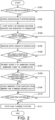
- FIG. 2 is a flowchart for illustrating an example of flow of processing performed by the controller 31.
- the processing flow illustrated in FIG. 2 is executed, for example, when an input operation for activating the gas turbine system 1 is performed by a user.
- the input operation performed by the user is received by, for example, the controller 31.
- the controller 31 determines in Step S101 whether or not an activation condition has been met.
- the activation condition is a condition for permitting the activation of the gas turbine system 1.
- the activation condition is that no abnormality has occurred in the devices of the gas turbine system 1 (for example, output values output from the devices include no abnormal value or no leakage of fluid from the flow passages has occurred).
- Step S101/YES When it is determined that the activation condition has been met (Step S101/YES), the processing proceeds to Step S102. Meanwhile, when it is determined that the activation condition has not been met (Step S101/NO), the processing proceeds to Step S111 and, as described later, the gas turbine system 1 is stopped.
- Step S101 the controller 31 causes the ignition device 13b to perform ignition in Step S102.
- Step S103 the controller 31 starts the supply of the cracked gas from the cracked-gas reservoir 17 to the combustor 13.
- the controller 31 controls the second flow rate control valve 22 so that the supply of the cracked gas from the cracked-gas reservoir 17 to the combustor 13 is started.
- the controller 31 opens the second flow rate control valve 22 that is in a closed state.
- the cracked gas is generated with the ammonia cracking catalyst 16, and the generated cracked gas is stored in the cracked-gas reservoir 17.
- the cracked gas is already stored in the cracked-gas reservoir 17.
- the cracked gas is already stored in the cracked-gas reservoir 17 by other method.
- ignition is performed under a state in which the cracked gas is supplied to the combustor 13. Specifically, the cracked gas is used as fuel for ignition. Unlike ammonia, hydrogen contained in the cracked gas is combustible and thus is more likely to be ignited. Hence, a failure in ignition is suppressed, and reliability of ignition is improved.
- Step S104 the controller 31 determines whether or not ignition has been successfully performed.
- Step S104/YES the processing proceeds to Step S105.
- Step S104/NO the processing proceeds to Step S111 and, as described later, the gas turbine system 1 is stopped.
- the controller 31 increases a supply amount of the cracked gas in Step S105. Specifically, the controller 31 controls the second flow rate control valve 22 so that the supply amount of the cracked gas from the cracked-gas reservoir 17 to the combustor 13 is increased. That is, the controller 31 increases the opening degree of the second flow rate control valve 22. For example, the controller 31 increases the supply amount of the cracked gas from the cracked-gas reservoir 17 to the combustor 13 in a preset change pattern.
- Step S106 the controller 31 determines whether or not the supply amount of the cracked gas has reached a reference supply amount.
- the reference supply amount is set to a value around which combustibility in the combustor 13 is maintained at a predetermined level or higher (specifically, non-combustion of part of ammonia is suppressed) even after the supply of ammonia to the combustor 13 is started.
- Step S106/YES When it is determined that the supply amount of the cracked gas has reached the reference supply amount (Step S106/YES), the controller 31 determines the combustibility in the combustor 13 is maintained at the predetermined level or higher even after the supply of ammonia to the combustor 13 is started, and the processing proceeds to Step S107. Meanwhile, when it is determined that the supply amount of the cracked gas has not reached the reference supply amount (Step S106/NO), the controller 31 determines that the combustibility in the combustor 13 becomes lower than the predetermined level after the supply of ammonia to the combustor 13 is started, and the processing returns to Step S105.
- the controller 31 permits the supply of ammonia from the ammonia tank 14 to the combustor 13 in Step S107. Specifically, when a required output for the gas turbine system 1 is equal to or larger than a reference output, the controller 31 starts the supply of ammonia from the ammonia tank 14 to the combustor 13. In this case, the controller 31 drives the pump 15 and controls the third flow rate control valve 23 so that the supply of ammonia from the ammonia tank 14 to the combustor 13 is started. Specifically, the controller 31 opens the third flow rate control valve 23 that is in a closed state. As a result, combustion using ammonia as fuel is started. When the required output for the gas turbine system 1 is smaller than the reference output, the supply of ammonia from the ammonia tank 14 to the combustor 13 is not required.
- the combustion using ammonia as fuel is started under a state in which the cracked gas is supplied to the combustor 13 and the combustibility is maintained at the predetermined level or higher.
- the cracked gas is used as auxiliary fuel (specifically, fuel for combustion aid).
- the controller 31 may continue or stop the supply of the cracked gas to the combustor 13.
- the cracked-gas generation condition is a condition for permitting the generation of the cracked gas (specifically, cracking of ammonia) with the ammonia cracking catalyst 16.
- the cracked-gas generation condition is that a temperature of the ammonia cracking catalyst 16 has become equal to or higher than a reference temperature (specifically, around a temperature at which the cracking of ammonia with the ammonia cracking catalyst 16 actively occurs).
- Step S108/YES When it is determined that the cracked-gas generation condition has been met (Step S108/YES), the processing proceeds to Step S109. Meanwhile, when it is determined that the cracked-gas generation condition has not been met (Step S108/NO), Step S109 is not carried out and the processing proceeds to Step S110.
- the controller 31 causes ammonia to be supplied from the ammonia tank 14 to the ammonia cracking catalyst 16 in Step S109. Specifically, the controller 31 controls the first flow rate control valve 21 so that ammonia is supplied from the ammonia tank 14 to the ammonia cracking catalyst 16. More specifically, the controller 31 opens the first flow rate control valve 21 that is in a closed state. As a result, the cracking of ammonia with the ammonia cracking catalyst 16 generates a cracked gas. Then, the generated cracked gas is sent to the cracked-gas reservoir 17, and a pressure in the cracked-gas reservoir 17 increases.
- Step S109 the controller 31 controls the supply amount of ammonia to the ammonia cracking catalyst 16 by using the first flow rate control valve 21 so that the pressure in the cracked-gas reservoir 17 becomes equal to a reference pressure.
- the above-mentioned control of the supply amount of ammonia to the ammonia cracking catalyst 16 (specifically, the control of the opening degree of the first flow rate control valve 21) is achieved by feedback control.
- the reference pressure is an index for determination of whether or not the cracked gas of an amount that is required as the amount of cracked gas to be used until the start of the supply of ammonia to the combustor 13 (hereinafter referred to simply as "required amount" of the cracked gas) is stored in the cracked-gas reservoir 17. For example, when the pressure in the cracked-gas reservoir 17 is lower than the reference pressure, the required amount of cracked gas is not stored in the cracked-gas reservoir 17.
- Step S110 the controller 31 determines whether or not stop conditions have been met.
- the stop conditions are conditions for permitting the stop of the gas turbine system 1.
- the stop conditions are that a request for power generation is no longer issued and the pressure in the cracked-gas reservoir 17 has become equal to or higher than the reference pressure.
- Step S110/YES When it is determined that the stop conditions have been met (Step S110/YES), the processing proceeds to Step S111. Meanwhile, when it is determined that the stop conditions have not been met (Step S110/NO), the processing returns to Step S108.
- Step S110 the controller 31 stops the gas turbine system 1 in Step S11, and the processing flow illustrated in FIG. 2 ends. Specifically, the controller 31 stops the supply of ammonia to the combustor 13, the supply of the cracked gas to the combustor 13, and the supply of ammonia to the ammonia cracking catalyst 16 to thereby stop the gas turbine system 1.
- the controller 31 does not stop the gas turbine system 1 and continues the supply of ammonia from the ammonia tank 14 to the ammonia cracking catalyst 16. As a result, after the pressure in the cracked-gas reservoir 17 returns to the reference pressure or a higher pressure, the gas turbine system 1 can be stopped.
- the ammonia cracking catalyst 16 is arranged on the downstream side of the turbine 11b in the exhaust flow passage 42.
- the ammonia cracking catalyst 16 is heated to a temperature around which the cracking of ammonia actively occurs (specifically, a temperature equal to or higher than the reference temperature) with the exhaust gas flowing through the exhaust flow passage 42.
- the heating of the ammonia cracking catalyst 16 can be achieved by effectively using the heat of the exhaust gas flowing through the exhaust flow passage 42.
- the heating of the ammonia cracking catalyst 16 is achieved without using a dedicated heater.
- the ammonia cracking catalyst 16 is connected to the combustor 13 through intermediation of the cracked-gas reservoir 17.
- ammonia is cracked with the ammonia cracking catalyst 16 to generate the cracked gas and thus the cracked gas can be stored in the cracked-gas reservoir 17 during the operation of the gas turbine system 1.
- ignition is performed with use of the cracked gas stored in the cracked-gas reservoir 17. As a result, a failure in ignition can be suppressed, and the reliability of ignition can be improved.
- the combustibility in the combustor 13 can be improved.
- the controller 31 controls the first flow rate control valve 21 so that ammonia is supplied from the ammonia tank 14 to the ammonia cracking catalyst 16 during an operation of the gas turbine system 1 (specifically, during an operation of the combustion device 10).
- the cracked gas can be generated with the ammonia cracking catalyst 16 and can be stored in the cracked-gas reservoir 17 in an appropriate manner during the operation of the gas turbine system 1.
- the controller 31 controls the second flow rate control valve 22 and the third flow rate control valve 23 so that supply of the ammonia from the ammonia tank 14 to the combustor 13 is started after supply of the cracked gas from the cracked-gas reservoir 17 to the combustor 13 is started at the time of activation of the gas turbine system 1 (specifically, at the time of activation of the combustion device 10).
- the cracked gas is used as fuel for ignition.
- a failure in ignition in the combustor 13 is suppressed, and the improvement of reliability of ignition can be appropriately achieved.
- gas turbine systems according to modification examples are described.
- processing performed by the controller 31 is similar to that performed by the controller 31 in the gas turbine system 1 described above, and thus description thereof is omitted.
- FIG. 3 is a schematic view for illustrating a configuration of a gas turbine system 1A according to a first modification example.
- the gas turbine system 1A according to the first modification example is different from the gas turbine system 1 described above in that a heat exchanger 51 is provided in the flow passage 46 and in that the flow passage 45 passes through the heat exchanger 51.
- the heat exchanger 51 corresponds to one example of a first heat exchanger according to the present disclosure.
- the combustor 13, the ammonia tank 14, the pump 15, the ammonia cracking catalyst 16, the cracked-gas reservoir 17, the first flow rate control valve 21, the second flow rate control valve 22, the third flow rate control valve 23, the controller 31, and the heat exchanger 51 of the gas turbine system 1A are included in a combustion device 10A.
- the flow passage 46 connects the ammonia cracking catalyst 16 and the cracked-gas reservoir 17 to each other.
- the heat exchanger 51 is provided in such flow passage 46.
- the flow passage 45 connects the ammonia tank 14 and the ammonia cracking catalyst 16 to each other. Such flow passage 45 passes through the heat exchanger 51.
- a cracked gas flowing through the flow passage 46 and ammonia flowing through the flow passage 45 exchange heat.
- a temperature of the cracked gas flowing through the flow passage 46 is higher than a temperature of ammonia flowing through the flow passage 45.
- heat is transferred from the cracked gas flowing through the flow passage 46 to ammonia flowing through the flow passage 45.
- the cracked gas flowing through the flow passage 46 is cooled.
- the heat exchanger 51 corresponds to a cooling device that cools the cracked gas flowing through the flow passage 46.
- a temperature of the cracked gas sent to the cracked-gas reservoir 17 is high (for example, about 500°C). However, a temperature of the cracked gas in the cracked-gas reservoir 17 decreases in a period from the time of stop of the gas turbine system 1 to the time of next activation. As the amount of decrease in temperature of the cracked gas in the cracked-gas reservoir 17 increases, a pressure in the cracked-gas reservoir 17 significantly decreases.
- the cooling device (specifically, the heat exchanger 51) is provided in the flow passage 46 that connects the ammonia cracking catalyst 16 and the cracked-gas reservoir 17 to each other.
- the temperature of the cracked gas sent to the cracked-gas reservoir 17 can be decreased.
- the amount of decrease in temperature of the cracked gas in the cracked-gas reservoir 17 can be reduced in a period from the time of stop of the gas turbine system 1 to the time of next activation.
- a reduction in pressure in the cracked-gas reservoir 17 can be suppressed.
- the pressure in the cracked-gas reservoir 17 can be set higher than a pressure in a combustion chamber 13a.
- the cracked gas can be appropriately supplied from the cracked-gas reservoir 17 to the combustor 13.
- the heat exchanger 51 through which the flow passage 45 passes is provided as a cooling device in the flow passage 46.
- the cooling device provided in the flow passage 46 is not limited to the heat exchanger 51.
- a device that cools the cracked gas flowing through the flow passage 46 with use of cooling water or air may be provided as a cooling device in the flow passage 46.
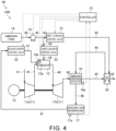
- FIG. 4 is a schematic view for illustrating a configuration of a gas turbine system 1B according to a second modification example.
- the gas turbine system 1B according to the second modification example is different from the gas turbine system 1 described above in that a heat exchanger 52 is provided in the exhaust flow passage 42 and in that the flow passage 45 passes through the heat exchanger 52.
- the heat exchanger 52 corresponds to one example of a second heat exchanger according to the present disclosure.
- the combustor 13, the ammonia tank 14, the pump 15, the ammonia cracking catalyst 16, the cracked-gas reservoir 17, the first flow rate control valve 21, the second flow rate control valve 22, the third flow rate control valve 23, the controller 31, and the heat exchanger 52 of the gas turbine system 1B are included in a combustion device 10B.
- the heat exchanger 52 is provided on a downstream side of the ammonia cracking catalyst 16 in the exhaust flow passage 42. As described above, the flow passage 45 connects the ammonia tank 14 and the ammonia cracking catalyst 16 to each other. Such flow passage 45 passes through the heat exchanger 52.
- ammonia flowing through the flow passage 45 and an exhaust gas flowing through the exhaust flow passage 42 exchange heat.
- a temperature of the exhaust gas flowing through the exhaust flow passage 42 is higher than a temperature of ammonia flowing through the flow passage 45.
- heat is transferred from the exhaust gas flowing through the exhaust flow passage 42 to ammonia flowing through the flow passage 45.
- the ammonia flowing through the flow passage 45 is heated and vaporized.
- the ammonia flowing through the flow passage 45 is heated in the heat exchanger 52 with the exhaust gas flowing through the exhaust flow passage 42, and then is sent to the ammonia cracking catalyst 16.
- efficiency of the cracking of ammonia with the ammonia cracking catalyst 16 is improved.
- a cracked gas can be efficiently stored in the cracked-gas reservoir 17.
- FIG. 5 is a schematic view for illustrating a configuration of a gas turbine system 1C according to a third modification example.
- the gas turbine system 1C according to the third modification example is different from the gas turbine system 1 described above in that a heat exchanger 53 and a heat exchanger 54 are provided in the exhaust flow passage 42 and in that a flow passage 48 passes through the heat exchanger 53 and the heat exchanger 54.
- the combustor 13, the ammonia tank 14, the pump 15, the ammonia cracking catalyst 16, the cracked-gas reservoir 17, the first flow rate control valve 21, the second flow rate control valve 22, the third flow rate control valve 23, and the controller 31 of the gas turbine system 1C are included in a combustion device 10C.
- the flow passage 48 is illustrated in a simplified manner in FIG. 5 , the flow passage 48 forms a closed circuit. Specifically, water circulates through the flow passage 48.
- a turbine (not shown) is provided in the flow passage 48. Power is obtained by the turbine with use of flow of water (specifically, steam).
- the flow passage 48, the heat exchanger 53, the heat exchanger 54, and the turbine are included in another system different from the gas turbine system 1C. Details of the above-mentioned another system are described with reference to FIG. 7 .
- the heat exchanger 53 is provided on a downstream side of the heat exchanger 54 in the exhaust flow passage 42.
- the heat exchanger 53 is provided on an upstream side of the heat exchanger 54 in the flow passage 48.
- liquid water flowing through the flow passage 48 is heated with an exhaust gas flowing through the exhaust flow passage 42.
- the heated liquid water is heated again with the exhaust gas flowing through the exhaust flow passage 42 in the heat exchanger 54 to be vaporized into gas (specifically, steam).
- the turbine (not shown) is rotated by the steam to thereby generate rotational power.
- the ammonia cracking catalyst 16 is arranged on an upstream side of the heat exchanger 53 and the heat exchanger 54 in the exhaust flow passage 42.
- the ammonia cracking catalyst 16 can be effectively heated with the exhaust gas.
- the ammonia cracking catalyst 16 may be arranged between the heat exchanger 54 and the heat exchanger 53 or on a downstream side of the heat exchanger 53 in the exhaust flow passage 42.
- FIG. 6 is a schematic view for illustrating a configuration of a gas turbine system 1D according to a fourth modification example.
- the gas turbine system 1D according to the fourth modification example is different from the gas turbine system 1C described above in that the heat exchanger 52 is provided in the exhaust flow passage 42 and in that the flow passage 45 passes through the heat exchanger 52.
- the heat exchanger 52 is provided on the downstream side of the heat exchanger 53 in the exhaust flow passage 42.
- the combustor 13, the ammonia tank 14, the pump 15, the ammonia cracking catalyst 16, the cracked-gas reservoir 17, the first flow rate control valve 21, the second flow rate control valve 22, the third flow rate control valve 23, the controller 31, and the heat exchanger 52 of the gas turbine system 1D are included in a combustion device 10D.
- the gas turbine system 1D As in the combustion device 10B of the gas turbine system 1B described above, in the gas turbine system 1D, ammonia flowing through the flow passage 45 is heated in the heat exchanger 52 with an exhaust gas flowing through the exhaust flow passage 42, and then is sent to the ammonia cracking catalyst 16.
- the efficiency of the cracking of ammonia with the ammonia cracking catalyst 16 is improved as compared to that in the gas turbine system 1C described above.
- the cracked gas can be efficiently stored in the cracked-gas reservoir 17.
- the heat exchanger 52 when the heat exchanger 52 is added to the gas turbine system 1C described above, it is preferred that the heat exchanger 52 be provided on the downstream side of the heat exchanger 53 in the exhaust flow passage 42.
- Ammonia vaporizes at a relatively low temperature (for example, about 60°C at 2 Mpa).
- a relatively low temperature for example, about 60°C at 2 Mpa.
- ammonia can be vaporized in the heat exchanger 52.
- an ammonia cracking promoting effect is achieved by adding the heat exchanger 52, and improvement of efficiency as a whole power generation system is achieved by the heat exchanger 53 and the heat exchanger 54.
- the exhaust gas flowing through the exhaust flow passage 42 is cooled in the heat exchanger 54 and the heat exchanger 53, and then is further cooled in the heat exchanger 52.
- the exhaust gas has a low temperature on the downstream side in the exhaust flow passage 42 as compared to that in the gas turbine system 1C described above.
- stainless steel be used as a material of members for forming the exhaust flow passage 42 and the heat exchanger 52 so as to suppress occurrence of dew condensation in the exhaust flow passage 42 and the heat exchanger 52.
- FIG. 7 is a schematic view for illustrating a configuration of a gas turbine system 1E according to a fifth modification example.
- the gas turbine system 1E according to the fifth modification example is different from the gas turbine system 1D described above in that a heat exchanger 55 is provided in the flow passage 48 and in that the flow passage 45 passes through the heat exchanger 55.
- the combustor 13, the ammonia tank 14, the pump 15, the ammonia cracking catalyst 16, the cracked-gas reservoir 17, the first flow rate control valve 21, the second flow rate control valve 22, the third flow rate control valve 23, the controller 31, the heat exchanger 52, and the heat exchanger 55 of the gas turbine system 1E are included in a combustion device 10E.
- FIG. 7 part of a system 2 including the flow passage 48, which is not shown in FIG. 5 and FIG. 6 , is also illustrated.
- the system 2 is a power generation system including the flow passage 48, the heat exchanger 53, the heat exchanger 54, the heat exchanger 55, a turbine 56, a power generator 57, and a drum 58.
- liquid water flowing through the flow passage 48 is heated and vaporized into gas (specifically, steam) in the heat exchanger 53 and the heat exchanger 54.
- the turbine 56 is provided on a downstream side of the heat exchanger 54 in the flow passage 48. The turbine 56 is rotated by the steam flowing through the flow passage 48 to thereby generate rotational power.
- the power generator 57 is connected to the turbine 56.
- the power generator 57 generates electric power with use of the rotational power generated by the turbine 56.
- the heat exchanger 55 and the drum 58 are arranged in the stated order from an upstream side so as to be located on a downstream side of the turbine 56 and on an upstream side of the heat exchanger 53 in the flow passage 48.
- the steam that has passed through the turbine 56 and ammonia flowing through the flow passage 45 exchange heat in the heat exchanger 55.
- the steam that has passed through the turbine 56 is cooled in the heat exchanger 55 with the ammonia flowing through the flow passage 45. Part of the steam passing through the heat exchanger 55 is liquified.
- the steam or water that has passed through the heat exchanger 55 is supplied to the drum 58.
- the water is sent from the drum 58 to the heat exchanger 53.
- the ammonia flowing through the flow passage 45 is heated in the heat exchanger 55 with the steam flowing through the flow passage 48. After that, ammonia flowing through the flow passage 45 is heated again in the heat exchanger 52 with an exhaust gas flowing through the exhaust flow passage 42, and then is sent to the ammonia cracking catalyst 16.
- the efficiency of the cracking of ammonia with the ammonia cracking catalyst 16 is improved as compared to that in the gas turbine system 1D described above.
- the cracked gas can be efficiently stored in the cracked-gas reservoir 17.
- the heat exchanger 52 is provided in the exhaust flow passage 42, and the flow passage 45 passes through the heat exchanger 52.
- the heat exchanger 52 may be omitted from the example of FIG. 7 .
- the ammonia flowing through the flow passage 45 passes through the heat exchanger 55, and then is sent to the ammonia cracking catalyst 16 without exchanging heat with the exhaust gas flowing through the exhaust flow passage 42.
- the degree of cooling of the exhaust gas flowing through the exhaust flow passage 42 is decreased, and thus a reduction in temperature of the exhaust gas on the downstream side in the exhaust flow passage 42 is suppressed.
- the degree of freedom in selection of a material for a member that forms the exhaust flow passage 42 is improved.
- the rotational power generated by the turbocharger 11 is used as energy for driving the power generator 12 in the gas turbine system 1, the gas turbine system 1A, the gas turbine system 1B, the gas turbine system 1C, the gas turbine system 1D, and the gas turbine system 1E.
- the rotational power generated by the turbocharger 11 in the gas turbine system 1, the gas turbine system 1A, the gas turbine system 1B, the gas turbine system 1C, the gas turbine system 1D, and the gas turbine system 1E may be used for other purposes of use (for example, for the purpose of driving a mobile body such as a vessel).
- liquid ammonia is mainly supplied to the combustor 13 and the ammonia cracking catalyst 16 in the gas turbine system 1, the gas turbine system 1A, the gas turbine system 1B, the gas turbine system 1C, the gas turbine system 1D, and the gas turbine system 1E.
- gaseous ammonia is supplied to the ammonia cracking catalyst 16 in the gas turbine system 1B, the gas turbine system 1D, and the gas turbine system 1E.
- gaseous ammonia may be supplied to the combustor 13 and the ammonia cracking catalyst 16 in the gas turbine system 1, the gas turbine system 1A, the gas turbine system 1B, the gas turbine system 1C, the gas turbine system 1D, and the gas turbine system 1E.
- a vaporizer may be provided on a downstream side of the pump 15 so that ammonia is supplied to the combustor 13 or the ammonia cracking catalyst 16 after being vaporized by the vaporizer.
- an accumulator may be provided on a downstream side of the vaporizer.
- the vaporizer and the accumulator may be provided in the flow passage 43 or may be provided in the flow passage 44 and the flow passage 45, respectively.
- the cooling device specifically, the heat exchanger 51
- the cooling device may be additionally provided in the flow passage 46 in the gas turbine system 1B, the gas turbine system 1C, the gas turbine system 1D, and the gas turbine system 1E.
Landscapes
- Engineering & Computer Science (AREA)
- Chemical & Material Sciences (AREA)
- Combustion & Propulsion (AREA)
- Mechanical Engineering (AREA)
- General Engineering & Computer Science (AREA)
- Chemical Kinetics & Catalysis (AREA)
- Engine Equipment That Uses Special Cycles (AREA)
- Incineration Of Waste (AREA)
- Separation By Low-Temperature Treatments (AREA)
- Turbine Rotor Nozzle Sealing (AREA)
- Exhaust Gas After Treatment (AREA)
Abstract
Description
- The present disclosure relates to a gas turbine system. This application claims the benefit of priority to
Japanese Patent Application No. 2021-057442 filed on March 30, 2021 - A gas turbine system that combusts fuel in a combustor to obtain power has been used. As the gas turbine system, for example, there exists a gas turbine system that uses ammonia as fuel, as disclosed in
Patent Literature 1. Emission of carbon dioxide is suppressed by using ammonia as fuel. - Patent Literature 1 :
JP 2016-191507 A - Ammonia has a property of being less combustible than other fuels (specifically, has flame retardancy). Thus, in the combustor in which ammonia is used as fuel, ignition fails in some cases. Further, even when ignition is successfully performed, part of the fuel may be discharged without being combusted.
- An object of the present disclosure is to provide a gas turbine system capable of improving combustibility in a combustor in which ammonia is used as fuel.
- In order to solve the above-mentioned problem, according to the present disclosure, there is provided a gas turbine system, including: an ammonia tank; a combustor connected to the ammonia tank; an exhaust flow passage connected to the combustor; a turbine provided in the exhaust flow passage; a cracked-gas reservoir connected to the combustor; and an ammonia cracking catalyst, which is arranged on a downstream side of the turbine in the exhaust flow passage, and is connected to the ammonia tank and the cracked-gas reservoir.
- A cooling device may be provided in a flow passage that connects the ammonia cracking catalyst and the cracked-gas reservoir to each other.
- The cooling device may be a first heat exchanger provided in a flow passage that connects the ammonia cracking catalyst and the cracked-gas reservoir to each other, and a flow passage that connects the ammonia tank and the ammonia cracking catalyst to each other may pass through the first heat exchanger.
- A second heat exchanger may be provided on a downstream side of the ammonia cracking catalyst in the exhaust flow passage, and a flow passage that connects the ammonia tank and the ammonia cracking catalyst to each other may pass through the second heat exchanger.
- A first flow rate control valve may be provided in a flow passage that connects the ammonia tank and the ammonia cracking catalyst to each other, and the gas turbine system may include a controller configured to control the first flow rate control valve so that ammonia is supplied from the ammonia tank to the ammonia cracking catalyst during an operation of the gas turbine system.
- A second flow rate control valve may be provided in a flow passage that connects the cracked-gas reservoir and the combustor to each other, a third flow rate control valve may be provided in a flow passage that connects the ammonia tank and the combustor to each other, and the controller may control the second flow rate control valve and the third flow rate control valve so that supply of the ammonia from the ammonia tank to the combustor is started after supply of a cracked gas from the cracked-gas reservoir to the combustor is started at the time of activation of the gas turbine system.
- According to the present disclosure, it is possible to improve combustibility in the combustor in which ammonia is used as fuel.
-
-
FIG. 1 is a schematic view for illustrating a configuration of a gas turbine system according to an embodiment of the present disclosure. -
FIG. 2 is a flowchart for illustrating an example of flow of processing performed by a controller according to the embodiment of the present disclosure. -
FIG. 3 is a schematic view for illustrating a configuration of a gas turbine system according to a first modification example. -
FIG. 4 is a schematic view for illustrating a configuration of a gas turbine system according to a second modification example. -
FIG. 5 is a schematic view for illustrating a configuration of a gas turbine system according to a third modification example. -
FIG. 6 is a schematic view for illustrating a configuration of a gas turbine system according to a fourth modification example. -
FIG. 7 is a schematic view for illustrating a configuration of a gas turbine system according to a fifth modification example. - Now, with reference to the attached drawings, an embodiment of the present disclosure is described. The dimensions, materials, and other specific numerical values represented in the embodiment are merely examples used for facilitating the understanding of the disclosure, and do not limit the present disclosure otherwise particularly noted. Elements having substantially the same functions and configurations herein and in the drawings are denoted by the same reference symbols to omit redundant description thereof. Further, illustration of elements with no direct relationship to the present disclosure is omitted.
-
FIG. 1 is a schematic view for illustrating a configuration of agas turbine system 1 according to this embodiment. As illustrated inFIG. 1 , thegas turbine system 1 includes aturbocharger 11, apower generator 12, acombustor 13, anammonia tank 14, apump 15, anammonia cracking catalyst 16, a cracked-gas reservoir 17, a first flowrate control valve 21, a second flowrate control valve 22, a third flowrate control valve 23, and acontroller 31. - The
combustor 13, theammonia tank 14, thepump 15, theammonia cracking catalyst 16, the cracked-gas reservoir 17, the first flowrate control valve 21, the second flowrate control valve 22, the third flowrate control valve 23, and thecontroller 31 of thegas turbine system 1 are included in acombustion device 10. - The
turbocharger 11 includes acompressor 11a and aturbine 11b. Thecompressor 11a and theturbine 11b rotate integrally. Thecompressor 11a and theturbine 11b are coupled to each other through intermediation of a shaft. - The
compressor 11a is provided in anintake flow passage 41 connected to thecombustor 13. Air to be supplied to thecombustor 13 flows through theintake flow passage 41. An intake port (not shown) is formed at an upstream-side end portion of theintake flow passage 41. The intake port allows air to be introduced from an outside. The air introduced through the intake port passes through thecompressor 11a and is sent to thecombustor 13. Thecompressor 11a compresses the air and discharges the compressed air to a downstream side. - The
turbine 11b is provided in anexhaust flow passage 42 connected to thecombustor 13. An exhaust gas discharged from thecombustor 13 flows through theexhaust flow passage 42. An exhaust port (not shown) is formed at a downstream-side end portion of theexhaust flow passage 42. The exhaust port allows the exhaust gas to be discharged to the outside. The exhaust gas discharged from thecombustor 13 passes through theturbine 11b and is sent to the exhaust port. Theturbine 11b is rotated by the exhaust gas to generate rotational power. - The
power generator 12 is connected to theturbocharger 11. Thepower generator 12 generates electric power with use of the rotational power generated by theturbocharger 11. - In the
combustor 13, ammonia is used as fuel to cause combustion. As described later, for example, at the time of activation of the gas turbine system 1 (specifically, at the time of activation of the combustion device 10), fuel other than ammonia (for example, a cracked gas serving as fuel for ignition) is also used. - The
combustor 13 includes acombustion chamber 13a and anignition device 13b. The air compressed by thecompressor 11a is supplied to thecombustion chamber 13a through theintake flow passage 41. Fuel is supplied to thecombustion chamber 13a. For example, liquid ammonia is supplied (more specifically, sprayed) as fuel to thecombustion chamber 13a from theammonia tank 14. An air-fuel mixture containing fuel and air is generated in thecombustion chamber 13a. Theignition device 13b ignites the air-fuel mixture in thecombustion chamber 13a. For example, theignition device 13b is provided inside thecombustion chamber 13a. An exhaust gas generated as a result of combustion in thecombustion chamber 13a is discharged to theexhaust flow passage 42. - The liquid ammonia is stored in the
ammonia tank 14. Theammonia tank 14 is connected to each of thecombustor 13 and theammonia cracking catalyst 16. In this manner, ammonia can be supplied from theammonia tank 14 to each of thecombustor 13 and theammonia cracking catalyst 16. - A
flow passage 43 is connected to theammonia tank 14. Aflow passage 44 and aflow passage 45 are connected to a downstream-side end portion of theflow passage 43. Theflow passage 44 is connected to thecombustor 13. That is, theammonia tank 14 is connected to thecombustor 13 through intermediation of theflow passage 43 and theflow passage 44. The liquid ammonia is supplied from theammonia tank 14 to the combustor 13 (specifically, thecombustion chamber 13a) via theflow passage 43 and theflow passage 44. Theflow passage 45 is connected to theammonia cracking catalyst 16. That is, theammonia tank 14 is connected to theammonia cracking catalyst 16 through intermediation of theflow passage 43 and theflow passage 45. The liquid ammonia is supplied from theammonia tank 14 to theammonia cracking catalyst 16 via theflow passage 43 and theflow passage 45. - The
pump 15 is provided in theflow passage 43. Thepump 15 feeds the ammonia supplied from theammonia tank 14 to a downstream side. The ammonia fed by thepump 15 passes through theflow passage 43 and is sent to theflow passage 44 and theflow passage 45. - The third flow
rate control valve 23 is provided in theflow passage 44. The third flowrate control valve 23 controls (that is, adjusts) a flow rate of ammonia flowing through theflow passage 44. Specifically, the third flowrate control valve 23 adjusts a supply amount of ammonia from theammonia tank 14 to thecombustor 13. The supply amount of ammonia from theammonia tank 14 to thecombustor 13 is adjusted through adjustment of an opening degree of the third flowrate control valve 23. - The first flow
rate control valve 21 is provided in theflow passage 45. The first flowrate control valve 21 controls (that is, adjusts) a flow rate of ammonia flowing through theflow passage 45. Specifically, the first flowrate control valve 21 adjusts a supply amount of ammonia from theammonia tank 14 to theammonia cracking catalyst 16. The supply amount of ammonia from theammonia tank 14 to theammonia cracking catalyst 16 is adjusted through adjustment of an opening degree of the first flowrate control valve 21. - The
ammonia cracking catalyst 16 cracks ammonia and generates a cracked gas. Theammonia cracking catalyst 16 cracks ammonia into hydrogen and nitrogen. Specifically, the cracked gas contains hydrogen and nitrogen. The cracked gas may contain uncracked ammonia in addition to hydrogen and nitrogen. The cracking of ammonia with theammonia cracking catalyst 16 occurs only when a temperature of theammonia cracking catalyst 16 is equal to or higher than a reference temperature (for example, from about 400°C to about 500°C). Specifically, when the temperature of theammonia cracking catalyst 16 becomes equal to or higher than the reference temperature, the cracking of ammonia can actively occur with theammonia cracking catalyst 16. - In this embodiment, the
ammonia cracking catalyst 16 is arranged on a downstream side of theturbine 11b in theexhaust flow passage 42. Specifically, heat exchange between theammonia cracking catalyst 16 and the exhaust gas in theexhaust flow passage 42 is enabled under a state in which an internal space of theammonia cracking catalyst 16 and theexhaust flow passage 42 are not in communication with each other. The exhaust gas flowing through theexhaust flow passage 42 has a high temperature (for example, about 550°C). Thus, theammonia cracking catalyst 16 is heated to a temperature around which the cracking of ammonia actively occurs (specifically, a temperature equal to or higher than the reference temperature) with the exhaust gas flowing through theexhaust flow passage 42 during an operation of the gas turbine system 1 (specifically, during an operation of the combustion device 10). - A
temperature sensor 16a is provided to theammonia cracking catalyst 16. Thetemperature sensor 16a detects a temperature of theammonia cracking catalyst 16. - The cracked-
gas reservoir 17 stores a cracked gas. The cracked-gas reservoir 17 is connected to theammonia cracking catalyst 16 through intermediation of aflow passage 46. The cracked gas generated as a result of cracking with theammonia cracking catalyst 16 is sent to the cracked-gas reservoir 17 via theflow passage 46. For example, a check valve for preventing backflow of the cracked gas from the cracked-gas reservoir 17 to theammonia cracking catalyst 16 or a shutoff valve may be provided in theflow passage 46. - A
pressure sensor 17a is provided to the cracked-gas reservoir 17. Thepressure sensor 17a detects a pressure in the cracked-gas reservoir 17. - The cracked-
gas reservoir 17 is connected to thecombustor 13 through intermediation of aflow passage 47. The cracked gas is supplied from the cracked-gas reservoir 17 via theflow passage 47 to the combustor 13 (specifically, thecombustion chamber 13a). - The second flow
rate control valve 22 is provided in theflow passage 47. The second flowrate control valve 22 controls (that is, adjusts) a flow rate of cracked gas flowing through theflow passage 47. Specifically, the second flowrate control valve 22 adjusts a supply amount of cracked gas from the cracked-gas reservoir 17 to thecombustor 13. The supply amount of cracked gas from the cracked-gas reservoir 17 to thecombustor 13 is adjusted through adjustment of an opening degree of the second flowrate control valve 22. - The
controller 31 includes, for example, a central processing unit (CPU), a ROM that stores, for example, a program, and a RAM serving as a work area. Thecontroller 31 controls the wholegas turbine system 1. For example, thecontroller 31 controls theignition device 13b, thepump 15, the first flowrate control valve 21, the second flowrate control valve 22, and the third flowrate control valve 23. Further, thecontroller 31 acquires detection results from thetemperature sensor 16a and thepressure sensor 17a. -
FIG. 2 is a flowchart for illustrating an example of flow of processing performed by thecontroller 31. The processing flow illustrated inFIG. 2 is executed, for example, when an input operation for activating thegas turbine system 1 is performed by a user. The input operation performed by the user is received by, for example, thecontroller 31. - After the processing flow illustrated in
FIG. 2 is started, thecontroller 31 determines in Step S101 whether or not an activation condition has been met. The activation condition is a condition for permitting the activation of thegas turbine system 1. For example, the activation condition is that no abnormality has occurred in the devices of the gas turbine system 1 (for example, output values output from the devices include no abnormal value or no leakage of fluid from the flow passages has occurred). - When it is determined that the activation condition has been met (Step S101/YES), the processing proceeds to Step S102. Meanwhile, when it is determined that the activation condition has not been met (Step S101/NO), the processing proceeds to Step S111 and, as described later, the
gas turbine system 1 is stopped. - When it is determined as YES in Step S101, the
controller 31 causes theignition device 13b to perform ignition in Step S102. Next, in Step S103, thecontroller 31 starts the supply of the cracked gas from the cracked-gas reservoir 17 to thecombustor 13. Specifically, thecontroller 31 controls the second flowrate control valve 22 so that the supply of the cracked gas from the cracked-gas reservoir 17 to thecombustor 13 is started. Specifically, thecontroller 31 opens the second flowrate control valve 22 that is in a closed state. - As described later, in the
gas turbine system 1, during the operation of thegas turbine system 1, the cracked gas is generated with theammonia cracking catalyst 16, and the generated cracked gas is stored in the cracked-gas reservoir 17. Thus, at the time of start of the processing flow illustrated inFIG. 2 , the cracked gas is already stored in the cracked-gas reservoir 17. However, at the time of first activation of thegas turbine system 1, the cracked gas is already stored in the cracked-gas reservoir 17 by other method. - As described above, in this embodiment, at the time of activation of the
gas turbine system 1, ignition is performed under a state in which the cracked gas is supplied to thecombustor 13. Specifically, the cracked gas is used as fuel for ignition. Unlike ammonia, hydrogen contained in the cracked gas is combustible and thus is more likely to be ignited. Hence, a failure in ignition is suppressed, and reliability of ignition is improved. - Next, in Step S104, the
controller 31 determines whether or not ignition has been successfully performed. When it is determined that the ignition has been successfully performed (Step S104/YES), the processing proceeds to Step S105. Meanwhile, when it is determined that the ignition has not been successfully performed (Step S104/NO), the processing proceeds to Step S111 and, as described later, thegas turbine system 1 is stopped. - When it is determined as YES in Step S104, the
controller 31 increases a supply amount of the cracked gas in Step S105. Specifically, thecontroller 31 controls the second flowrate control valve 22 so that the supply amount of the cracked gas from the cracked-gas reservoir 17 to thecombustor 13 is increased. That is, thecontroller 31 increases the opening degree of the second flowrate control valve 22. For example, thecontroller 31 increases the supply amount of the cracked gas from the cracked-gas reservoir 17 to thecombustor 13 in a preset change pattern. - Next, in Step S106, the
controller 31 determines whether or not the supply amount of the cracked gas has reached a reference supply amount. For example, the reference supply amount is set to a value around which combustibility in thecombustor 13 is maintained at a predetermined level or higher (specifically, non-combustion of part of ammonia is suppressed) even after the supply of ammonia to thecombustor 13 is started. - When it is determined that the supply amount of the cracked gas has reached the reference supply amount (Step S106/YES), the
controller 31 determines the combustibility in thecombustor 13 is maintained at the predetermined level or higher even after the supply of ammonia to thecombustor 13 is started, and the processing proceeds to Step S107. Meanwhile, when it is determined that the supply amount of the cracked gas has not reached the reference supply amount (Step S106/NO), thecontroller 31 determines that the combustibility in thecombustor 13 becomes lower than the predetermined level after the supply of ammonia to thecombustor 13 is started, and the processing returns to Step S105. - When it is determined as YES in Step S106, the
controller 31 permits the supply of ammonia from theammonia tank 14 to thecombustor 13 in Step S107. Specifically, when a required output for thegas turbine system 1 is equal to or larger than a reference output, thecontroller 31 starts the supply of ammonia from theammonia tank 14 to thecombustor 13. In this case, thecontroller 31 drives thepump 15 and controls the third flowrate control valve 23 so that the supply of ammonia from theammonia tank 14 to thecombustor 13 is started. Specifically, thecontroller 31 opens the third flowrate control valve 23 that is in a closed state. As a result, combustion using ammonia as fuel is started. When the required output for thegas turbine system 1 is smaller than the reference output, the supply of ammonia from theammonia tank 14 to thecombustor 13 is not required. - In the
gas turbine system 1, the combustion using ammonia as fuel is started under a state in which the cracked gas is supplied to thecombustor 13 and the combustibility is maintained at the predetermined level or higher. Specifically, the cracked gas is used as auxiliary fuel (specifically, fuel for combustion aid). As a result, non-combustion of part of ammonia is suppressed. After the supply of ammonia to thecombustor 13 is started, thecontroller 31 may continue or stop the supply of the cracked gas to thecombustor 13. - Next, in Step S108, the
controller 31 determines whether or not a cracked-gas generation condition has been met. The cracked-gas generation condition is a condition for permitting the generation of the cracked gas (specifically, cracking of ammonia) with theammonia cracking catalyst 16. For example, the cracked-gas generation condition is that a temperature of theammonia cracking catalyst 16 has become equal to or higher than a reference temperature (specifically, around a temperature at which the cracking of ammonia with theammonia cracking catalyst 16 actively occurs). - When it is determined that the cracked-gas generation condition has been met (Step S108/YES), the processing proceeds to Step S109. Meanwhile, when it is determined that the cracked-gas generation condition has not been met (Step S108/NO), Step S109 is not carried out and the processing proceeds to Step S110.
- When it is determined as YES in Step S108, the
controller 31 causes ammonia to be supplied from theammonia tank 14 to theammonia cracking catalyst 16 in Step S109. Specifically, thecontroller 31 controls the first flowrate control valve 21 so that ammonia is supplied from theammonia tank 14 to theammonia cracking catalyst 16. More specifically, thecontroller 31 opens the first flowrate control valve 21 that is in a closed state. As a result, the cracking of ammonia with theammonia cracking catalyst 16 generates a cracked gas. Then, the generated cracked gas is sent to the cracked-gas reservoir 17, and a pressure in the cracked-gas reservoir 17 increases. - In Step S109, the
controller 31 controls the supply amount of ammonia to theammonia cracking catalyst 16 by using the first flowrate control valve 21 so that the pressure in the cracked-gas reservoir 17 becomes equal to a reference pressure. Specifically, the above-mentioned control of the supply amount of ammonia to the ammonia cracking catalyst 16 (specifically, the control of the opening degree of the first flow rate control valve 21) is achieved by feedback control. The reference pressure is an index for determination of whether or not the cracked gas of an amount that is required as the amount of cracked gas to be used until the start of the supply of ammonia to the combustor 13 (hereinafter referred to simply as "required amount" of the cracked gas) is stored in the cracked-gas reservoir 17. For example, when the pressure in the cracked-gas reservoir 17 is lower than the reference pressure, the required amount of cracked gas is not stored in the cracked-gas reservoir 17. - Next, in Step S110, the
controller 31 determines whether or not stop conditions have been met. The stop conditions are conditions for permitting the stop of thegas turbine system 1. For example, the stop conditions are that a request for power generation is no longer issued and the pressure in the cracked-gas reservoir 17 has become equal to or higher than the reference pressure. - When it is determined that the stop conditions have been met (Step S110/YES), the processing proceeds to Step S111. Meanwhile, when it is determined that the stop conditions have not been met (Step S110/NO), the processing returns to Step S108.
- When it is determined as YES in Step S110, the
controller 31 stops thegas turbine system 1 in Step S11, and the processing flow illustrated inFIG. 2 ends. Specifically, thecontroller 31 stops the supply of ammonia to thecombustor 13, the supply of the cracked gas to thecombustor 13, and the supply of ammonia to theammonia cracking catalyst 16 to thereby stop thegas turbine system 1. - As described above, when the pressure in the cracked-
gas reservoir 17 is lower than the reference pressure, thecontroller 31 does not stop thegas turbine system 1 and continues the supply of ammonia from theammonia tank 14 to theammonia cracking catalyst 16. As a result, after the pressure in the cracked-gas reservoir 17 returns to the reference pressure or a higher pressure, thegas turbine system 1 can be stopped. - As described above, in the
gas turbine system 1, theammonia cracking catalyst 16 is arranged on the downstream side of theturbine 11b in theexhaust flow passage 42. Thus, theammonia cracking catalyst 16 is heated to a temperature around which the cracking of ammonia actively occurs (specifically, a temperature equal to or higher than the reference temperature) with the exhaust gas flowing through theexhaust flow passage 42. As described above, the heating of theammonia cracking catalyst 16 can be achieved by effectively using the heat of the exhaust gas flowing through theexhaust flow passage 42. Thus, the heating of theammonia cracking catalyst 16 is achieved without using a dedicated heater. - Further, in the
gas turbine system 1, theammonia cracking catalyst 16 is connected to thecombustor 13 through intermediation of the cracked-gas reservoir 17. As a result, ammonia is cracked with theammonia cracking catalyst 16 to generate the cracked gas and thus the cracked gas can be stored in the cracked-gas reservoir 17 during the operation of thegas turbine system 1. Then, at the time of next activation of thegas turbine system 1, ignition is performed with use of the cracked gas stored in the cracked-gas reservoir 17. As a result, a failure in ignition can be suppressed, and the reliability of ignition can be improved. - As described above, with the
gas turbine system 1, the combustibility in thecombustor 13 can be improved. - In particular, the
controller 31 controls the first flowrate control valve 21 so that ammonia is supplied from theammonia tank 14 to theammonia cracking catalyst 16 during an operation of the gas turbine system 1 (specifically, during an operation of the combustion device 10). Thus, the cracked gas can be generated with theammonia cracking catalyst 16 and can be stored in the cracked-gas reservoir 17 in an appropriate manner during the operation of thegas turbine system 1. - In particular, the
controller 31 controls the second flowrate control valve 22 and the third flowrate control valve 23 so that supply of the ammonia from theammonia tank 14 to thecombustor 13 is started after supply of the cracked gas from the cracked-gas reservoir 17 to thecombustor 13 is started at the time of activation of the gas turbine system 1 (specifically, at the time of activation of the combustion device 10). Thus, at the time of activation of thegas turbine system 1, the cracked gas is used as fuel for ignition. As a result, a failure in ignition in thecombustor 13 is suppressed, and the improvement of reliability of ignition can be appropriately achieved. - Now, with reference to
FIG. 3 to FIG. 7 , gas turbine systems according to modification examples are described. In the gas turbine systems according to modification examples described below, processing performed by thecontroller 31 is similar to that performed by thecontroller 31 in thegas turbine system 1 described above, and thus description thereof is omitted. -
FIG. 3 is a schematic view for illustrating a configuration of agas turbine system 1A according to a first modification example. As illustrated inFIG. 3 , thegas turbine system 1A according to the first modification example is different from thegas turbine system 1 described above in that aheat exchanger 51 is provided in theflow passage 46 and in that theflow passage 45 passes through theheat exchanger 51. Theheat exchanger 51 corresponds to one example of a first heat exchanger according to the present disclosure. - In the first modification example, the
combustor 13, theammonia tank 14, thepump 15, theammonia cracking catalyst 16, the cracked-gas reservoir 17, the first flowrate control valve 21, the second flowrate control valve 22, the third flowrate control valve 23, thecontroller 31, and theheat exchanger 51 of thegas turbine system 1A are included in acombustion device 10A. - As described above, the
flow passage 46 connects theammonia cracking catalyst 16 and the cracked-gas reservoir 17 to each other. Theheat exchanger 51 is provided insuch flow passage 46. As described above, theflow passage 45 connects theammonia tank 14 and theammonia cracking catalyst 16 to each other.Such flow passage 45 passes through theheat exchanger 51. - In the
heat exchanger 51, a cracked gas flowing through theflow passage 46 and ammonia flowing through theflow passage 45 exchange heat. A temperature of the cracked gas flowing through theflow passage 46 is higher than a temperature of ammonia flowing through theflow passage 45. Thus, in theheat exchanger 51, heat is transferred from the cracked gas flowing through theflow passage 46 to ammonia flowing through theflow passage 45. Thus, the cracked gas flowing through theflow passage 46 is cooled. As described above, theheat exchanger 51 corresponds to a cooling device that cools the cracked gas flowing through theflow passage 46. - A temperature of the cracked gas sent to the cracked-
gas reservoir 17 is high (for example, about 500°C). However, a temperature of the cracked gas in the cracked-gas reservoir 17 decreases in a period from the time of stop of thegas turbine system 1 to the time of next activation. As the amount of decrease in temperature of the cracked gas in the cracked-gas reservoir 17 increases, a pressure in the cracked-gas reservoir 17 significantly decreases. - In the
gas turbine system 1A, the cooling device (specifically, the heat exchanger 51) is provided in theflow passage 46 that connects theammonia cracking catalyst 16 and the cracked-gas reservoir 17 to each other. As a result, the temperature of the cracked gas sent to the cracked-gas reservoir 17 can be decreased. Thus, the amount of decrease in temperature of the cracked gas in the cracked-gas reservoir 17 can be reduced in a period from the time of stop of thegas turbine system 1 to the time of next activation. Thus, a reduction in pressure in the cracked-gas reservoir 17 can be suppressed. In this manner, the pressure in the cracked-gas reservoir 17 can be set higher than a pressure in acombustion chamber 13a. Thus, the cracked gas can be appropriately supplied from the cracked-gas reservoir 17 to thecombustor 13. - There has been described above an example in which the
heat exchanger 51 through which theflow passage 45 passes is provided as a cooling device in theflow passage 46. However, the cooling device provided in theflow passage 46 is not limited to theheat exchanger 51. For example, a device that cools the cracked gas flowing through theflow passage 46 with use of cooling water or air may be provided as a cooling device in theflow passage 46. -
FIG. 4 is a schematic view for illustrating a configuration of agas turbine system 1B according to a second modification example. As illustrated inFIG. 4 , thegas turbine system 1B according to the second modification example is different from thegas turbine system 1 described above in that aheat exchanger 52 is provided in theexhaust flow passage 42 and in that theflow passage 45 passes through theheat exchanger 52. Theheat exchanger 52 corresponds to one example of a second heat exchanger according to the present disclosure. - In the second modification example, the
combustor 13, theammonia tank 14, thepump 15, theammonia cracking catalyst 16, the cracked-gas reservoir 17, the first flowrate control valve 21, the second flowrate control valve 22, the third flowrate control valve 23, thecontroller 31, and theheat exchanger 52 of thegas turbine system 1B are included in acombustion device 10B. - The
heat exchanger 52 is provided on a downstream side of theammonia cracking catalyst 16 in theexhaust flow passage 42. As described above, theflow passage 45 connects theammonia tank 14 and theammonia cracking catalyst 16 to each other.Such flow passage 45 passes through theheat exchanger 52. - In the
heat exchanger 52, ammonia flowing through theflow passage 45 and an exhaust gas flowing through theexhaust flow passage 42 exchange heat. A temperature of the exhaust gas flowing through theexhaust flow passage 42 is higher than a temperature of ammonia flowing through theflow passage 45. Thus, in theheat exchanger 51, heat is transferred from the exhaust gas flowing through theexhaust flow passage 42 to ammonia flowing through theflow passage 45. Thus, the ammonia flowing through theflow passage 45 is heated and vaporized. - In the
gas turbine system 1B, the ammonia flowing through theflow passage 45 is heated in theheat exchanger 52 with the exhaust gas flowing through theexhaust flow passage 42, and then is sent to theammonia cracking catalyst 16. Thus, efficiency of the cracking of ammonia with theammonia cracking catalyst 16 is improved. Hence, a cracked gas can be efficiently stored in the cracked-gas reservoir 17. -
FIG. 5 is a schematic view for illustrating a configuration of agas turbine system 1C according to a third modification example. As illustrated inFIG. 5 , thegas turbine system 1C according to the third modification example is different from thegas turbine system 1 described above in that aheat exchanger 53 and aheat exchanger 54 are provided in theexhaust flow passage 42 and in that aflow passage 48 passes through theheat exchanger 53 and theheat exchanger 54. - In the third modification example, the
combustor 13, theammonia tank 14, thepump 15, theammonia cracking catalyst 16, the cracked-gas reservoir 17, the first flowrate control valve 21, the second flowrate control valve 22, the third flowrate control valve 23, and thecontroller 31 of thegas turbine system 1C are included in acombustion device 10C. - Water flows through the
flow passage 48. Although theflow passage 48 is illustrated in a simplified manner inFIG. 5 , theflow passage 48 forms a closed circuit. Specifically, water circulates through theflow passage 48. A turbine (not shown) is provided in theflow passage 48. Power is obtained by the turbine with use of flow of water (specifically, steam). Theflow passage 48, theheat exchanger 53, theheat exchanger 54, and the turbine (not shown) are included in another system different from thegas turbine system 1C. Details of the above-mentioned another system are described with reference toFIG. 7 . - The
heat exchanger 53 is provided on a downstream side of theheat exchanger 54 in theexhaust flow passage 42. Theheat exchanger 53 is provided on an upstream side of theheat exchanger 54 in theflow passage 48. In theheat exchanger 53, liquid water flowing through theflow passage 48 is heated with an exhaust gas flowing through theexhaust flow passage 42. Then, the heated liquid water is heated again with the exhaust gas flowing through theexhaust flow passage 42 in theheat exchanger 54 to be vaporized into gas (specifically, steam). Then, the turbine (not shown) is rotated by the steam to thereby generate rotational power. - As described above, a part of the
gas turbine system 1C is shared by another system. A configuration and a purpose of use of another system having a part shared by thegas turbine system 1C are not limited to those in the example described above. In such a case, effects obtained by thegas turbine system 1 described above are produced. In an example ofFIG. 5 , theammonia cracking catalyst 16 is arranged on an upstream side of theheat exchanger 53 and theheat exchanger 54 in theexhaust flow passage 42. Thus, theammonia cracking catalyst 16 can be effectively heated with the exhaust gas. However, theammonia cracking catalyst 16 may be arranged between theheat exchanger 54 and theheat exchanger 53 or on a downstream side of theheat exchanger 53 in theexhaust flow passage 42. -
FIG. 6 is a schematic view for illustrating a configuration of agas turbine system 1D according to a fourth modification example. As illustrated inFIG. 6 , thegas turbine system 1D according to the fourth modification example is different from thegas turbine system 1C described above in that theheat exchanger 52 is provided in theexhaust flow passage 42 and in that theflow passage 45 passes through theheat exchanger 52. Theheat exchanger 52 is provided on the downstream side of theheat exchanger 53 in theexhaust flow passage 42. - In the fourth modification example, the
combustor 13, theammonia tank 14, thepump 15, theammonia cracking catalyst 16, the cracked-gas reservoir 17, the first flowrate control valve 21, the second flowrate control valve 22, the third flowrate control valve 23, thecontroller 31, and theheat exchanger 52 of thegas turbine system 1D are included in acombustion device 10D. - As in the
combustion device 10B of thegas turbine system 1B described above, in thegas turbine system 1D, ammonia flowing through theflow passage 45 is heated in theheat exchanger 52 with an exhaust gas flowing through theexhaust flow passage 42, and then is sent to theammonia cracking catalyst 16. Thus, the efficiency of the cracking of ammonia with theammonia cracking catalyst 16 is improved as compared to that in thegas turbine system 1C described above. Hence, the cracked gas can be efficiently stored in the cracked-gas reservoir 17. Further, when theheat exchanger 52 is added to thegas turbine system 1C described above, it is preferred that theheat exchanger 52 be provided on the downstream side of theheat exchanger 53 in theexhaust flow passage 42. Ammonia vaporizes at a relatively low temperature (for example, about 60°C at 2 Mpa). Thus, also in the above-mentioned case, ammonia can be vaporized in theheat exchanger 52. Further, an ammonia cracking promoting effect is achieved by adding theheat exchanger 52, and improvement of efficiency as a whole power generation system is achieved by theheat exchanger 53 and theheat exchanger 54. - In the
gas turbine system 1D, however, the exhaust gas flowing through theexhaust flow passage 42 is cooled in theheat exchanger 54 and theheat exchanger 53, and then is further cooled in theheat exchanger 52. Thus, the exhaust gas has a low temperature on the downstream side in theexhaust flow passage 42 as compared to that in thegas turbine system 1C described above. Hence, it is preferred that, for example, stainless steel be used as a material of members for forming theexhaust flow passage 42 and theheat exchanger 52 so as to suppress occurrence of dew condensation in theexhaust flow passage 42 and theheat exchanger 52. -
FIG. 7 is a schematic view for illustrating a configuration of agas turbine system 1E according to a fifth modification example. As illustrated inFIG. 7 , thegas turbine system 1E according to the fifth modification example is different from thegas turbine system 1D described above in that aheat exchanger 55 is provided in theflow passage 48 and in that theflow passage 45 passes through theheat exchanger 55. - In the fifth modification example, the
combustor 13, theammonia tank 14, thepump 15, theammonia cracking catalyst 16, the cracked-gas reservoir 17, the first flowrate control valve 21, the second flowrate control valve 22, the third flowrate control valve 23, thecontroller 31, theheat exchanger 52, and theheat exchanger 55 of thegas turbine system 1E are included in acombustion device 10E. - In
FIG. 7 , part of asystem 2 including theflow passage 48, which is not shown inFIG. 5 andFIG. 6 , is also illustrated. Thesystem 2 is a power generation system including theflow passage 48, theheat exchanger 53, theheat exchanger 54, theheat exchanger 55, aturbine 56, apower generator 57, and adrum 58. As described above, liquid water flowing through theflow passage 48 is heated and vaporized into gas (specifically, steam) in theheat exchanger 53 and theheat exchanger 54. Theturbine 56 is provided on a downstream side of theheat exchanger 54 in theflow passage 48. Theturbine 56 is rotated by the steam flowing through theflow passage 48 to thereby generate rotational power. - The
power generator 57 is connected to theturbine 56. Thepower generator 57 generates electric power with use of the rotational power generated by theturbine 56. Theheat exchanger 55 and thedrum 58 are arranged in the stated order from an upstream side so as to be located on a downstream side of theturbine 56 and on an upstream side of theheat exchanger 53 in theflow passage 48. The steam that has passed through theturbine 56 and ammonia flowing through theflow passage 45 exchange heat in theheat exchanger 55. The steam that has passed through theturbine 56 is cooled in theheat exchanger 55 with the ammonia flowing through theflow passage 45. Part of the steam passing through theheat exchanger 55 is liquified. Then, the steam or water that has passed through theheat exchanger 55 is supplied to thedrum 58. The water is sent from thedrum 58 to theheat exchanger 53. - In the
gas turbine system 1E, the ammonia flowing through theflow passage 45 is heated in theheat exchanger 55 with the steam flowing through theflow passage 48. After that, ammonia flowing through theflow passage 45 is heated again in theheat exchanger 52 with an exhaust gas flowing through theexhaust flow passage 42, and then is sent to theammonia cracking catalyst 16. Thus, the efficiency of the cracking of ammonia with theammonia cracking catalyst 16 is improved as compared to that in thegas turbine system 1D described above. Hence, the cracked gas can be efficiently stored in the cracked-gas reservoir 17. - In an example of
FIG. 7 , theheat exchanger 52 is provided in theexhaust flow passage 42, and theflow passage 45 passes through theheat exchanger 52. However, theheat exchanger 52 may be omitted from the example ofFIG. 7 . In this case, the ammonia flowing through theflow passage 45 passes through theheat exchanger 55, and then is sent to theammonia cracking catalyst 16 without exchanging heat with the exhaust gas flowing through theexhaust flow passage 42. As a result, the degree of cooling of the exhaust gas flowing through theexhaust flow passage 42 is decreased, and thus a reduction in temperature of the exhaust gas on the downstream side in theexhaust flow passage 42 is suppressed. Thus, the degree of freedom in selection of a material for a member that forms theexhaust flow passage 42 is improved. - The embodiment of the present disclosure has been described above with reference to the attached drawings, but, needless to say, the present disclosure is not limited to the above-mentioned embodiment. It is apparent that those skilled in the art may arrive at various alternations and modifications within the scope of claims, and those examples are construed as naturally falling within the technical scope of the present disclosure.
- There have been described above examples in which the rotational power generated by the
turbocharger 11 is used as energy for driving thepower generator 12 in thegas turbine system 1, thegas turbine system 1A, thegas turbine system 1B, thegas turbine system 1C, thegas turbine system 1D, and thegas turbine system 1E. However, the rotational power generated by theturbocharger 11 in thegas turbine system 1, thegas turbine system 1A, thegas turbine system 1B, thegas turbine system 1C, thegas turbine system 1D, and thegas turbine system 1E may be used for other purposes of use (for example, for the purpose of driving a mobile body such as a vessel). - There have been described above examples in which liquid ammonia is mainly supplied to the
combustor 13 and theammonia cracking catalyst 16 in thegas turbine system 1, thegas turbine system 1A, thegas turbine system 1B, thegas turbine system 1C, thegas turbine system 1D, and thegas turbine system 1E. Specifically, gaseous ammonia is supplied to theammonia cracking catalyst 16 in thegas turbine system 1B, thegas turbine system 1D, and thegas turbine system 1E. However, gaseous ammonia may be supplied to thecombustor 13 and theammonia cracking catalyst 16 in thegas turbine system 1, thegas turbine system 1A, thegas turbine system 1B, thegas turbine system 1C, thegas turbine system 1D, and thegas turbine system 1E. For example, a vaporizer may be provided on a downstream side of thepump 15 so that ammonia is supplied to thecombustor 13 or theammonia cracking catalyst 16 after being vaporized by the vaporizer. In this case, an accumulator may be provided on a downstream side of the vaporizer. The vaporizer and the accumulator may be provided in theflow passage 43 or may be provided in theflow passage 44 and theflow passage 45, respectively. - There has been described above the
gas turbine system 1A corresponding to thegas turbine system 1, in which the cooling device (specifically, the heat exchanger 51) is additionally provided in theflow passage 46. However, the cooling device (specifically, the heat exchanger 51) may be additionally provided in theflow passage 46 in thegas turbine system 1B, thegas turbine system 1C, thegas turbine system 1D, and thegas turbine system 1E. - 1: gas turbine system, 1A: gas turbine system, 1B: gas turbine system, 1C: gas turbine system, 1D: gas turbine system, 1E: gas turbine system, 11b: turbine, 13: combustor, 14: ammonia tank, 16: ammonia cracking catalyst, 17: cracked-gas reservoir, 21: first flow rate control valve, 22: second flow rate control valve, 23: third flow rate control valve, 31: controller, 42: exhaust flow passage, 43: flow passage, 44: flow passage, 45: flow passage, 46: flow passage, 47: flow passage, 51: heat exchanger (cooling device, first heat exchanger), 52: heat exchanger (second heat exchanger)
Claims (6)
- A gas turbine system, comprising:an ammonia tank;a combustor connected to the ammonia tank;an exhaust flow passage connected to the combustor;a turbine provided in the exhaust flow passage;a cracked-gas reservoir connected to the combustor; andan ammonia cracking catalyst, which is arranged on a downstream side of the turbine in the exhaust flow passage, and is connected to the ammonia tank and the cracked-gas reservoir.
- The gas turbine system according to claim 1, wherein a cooling device is provided in a flow passage that connects the ammonia cracking catalyst and the cracked-gas reservoir to each other.
- The gas turbine system according to claim 2,wherein the cooling device is a first heat exchanger provided in a flow passage that connects the ammonia cracking catalyst and the cracked-gas reservoir to each other, andwherein a flow passage that connects the ammonia tank and the ammonia cracking catalyst to each other passes through the first heat exchanger.
- The gas turbine system according to any one of claims 1 to 3,wherein a second heat exchanger is provided on a downstream side of the ammonia cracking catalyst in the exhaust flow passage, andwherein a flow passage that connects the ammonia tank and the ammonia cracking catalyst to each other passes through the second heat exchanger.
- The gas turbine system according to any one of claims 1 to 4,wherein a first flow rate control valve is provided in a flow passage that connects the ammonia tank and the ammonia cracking catalyst to each other, andwherein the gas turbine system comprises a controller configured to control the first flow rate control valve so that ammonia is supplied from the ammonia tank to the ammonia cracking catalyst during an operation of the gas turbine system.
- The gas turbine system according to claim 5,wherein a second flow rate control valve is provided in a flow passage that connects the cracked-gas reservoir and the combustor to each other,wherein a third flow rate control valve is provided in a flow passage that connects the ammonia tank and the combustor to each other, andwherein the controller controls the second flow rate control valve and the third flow rate control valve so that supply of the ammonia from the ammonia tank to the combustor is started after supply of a cracked gas from the cracked-gas reservoir to the combustor is started at the time of activation of the gas turbine system.
Applications Claiming Priority (2)
| Application Number | Priority Date | Filing Date | Title |
|---|---|---|---|
| JP2021057442 | 2021-03-30 | ||
| PCT/JP2022/009180 WO2022209563A1 (en) | 2021-03-30 | 2022-03-03 | Gas turbine system |
Publications (2)
| Publication Number | Publication Date |
|---|---|
| EP4317666A1 true EP4317666A1 (en) | 2024-02-07 |
| EP4317666A4 EP4317666A4 (en) | 2025-04-09 |
Family
ID=83458551
Family Applications (1)
| Application Number | Title | Priority Date | Filing Date |
|---|---|---|---|
| EP22779788.3A Pending EP4317666A4 (en) | 2021-03-30 | 2022-03-03 | GAS TURBINE PLANT |
Country Status (7)
| Country | Link |
|---|---|
| US (1) | US12429225B2 (en) |
| EP (1) | EP4317666A4 (en) |
| JP (1) | JP7626201B2 (en) |
| KR (1) | KR102860599B1 (en) |
| CN (1) | CN116940755A (en) |
| AU (1) | AU2022251107B2 (en) |
| WO (1) | WO2022209563A1 (en) |
Families Citing this family (11)
| Publication number | Priority date | Publication date | Assignee | Title |
|---|---|---|---|---|
| CN117120710A (en) * | 2021-04-14 | 2023-11-24 | 株式会社Ihi | Combustion devices and gas turbine systems |
| GB2608643B (en) * | 2021-07-09 | 2025-01-08 | Reaction Engines Ltd | Thermally integrated ammonia fuelled engine |
| WO2023098619A1 (en) * | 2021-11-30 | 2023-06-08 | 上海慕帆动力科技有限公司 | Power generation system, dynamic adjustment method for power generation system, and control method for power generation system |
| JP7556381B2 (en) * | 2022-10-31 | 2024-09-26 | 株式会社Ihi | Gas Turbine Systems |
| KR102897162B1 (en) | 2023-05-30 | 2025-12-09 | 두산에너빌리티 주식회사 | Gas turbine plant with ammonia decomposition system |
| US12385433B2 (en) | 2023-05-30 | 2025-08-12 | Doosan Enerbility Co., Ltd. | Gas turbine plant with ammonia decomposition system |
| KR20240171446A (en) | 2023-05-30 | 2024-12-09 | 두산에너빌리티 주식회사 | Gas turbine plant with ammonia decomposition system |
| US12264621B2 (en) * | 2023-05-30 | 2025-04-01 | Doosan Enerbility Co., Ltd. | Gas turbine plant with ammonia decomposition system |
| KR102897161B1 (en) | 2023-05-30 | 2025-12-09 | 두산에너빌리티 주식회사 | Gas turbine plant with ammonia decomposition system |
| KR102921605B1 (en) | 2023-05-30 | 2026-02-02 | 두산에너빌리티 주식회사 | Gas turbine plant with ammonia decomposition system |
| WO2025262226A1 (en) * | 2024-06-21 | 2025-12-26 | Nuovo Pignone Tecnologie - S.R.L. | A method of controlling the conditioning of a fuel feed to a power generating system comprising a gas turbine, and a related gas turbine auxiliary system for feed conditioning |
Family Cites Families (16)
| Publication number | Priority date | Publication date | Assignee | Title |
|---|---|---|---|---|
| JP2948351B2 (en) | 1991-05-17 | 1999-09-13 | 三菱重工業株式会社 | Turbine plant |
| JPH10110630A (en) * | 1996-10-08 | 1998-04-28 | Toshiba Corp | Gas turbine combustor fuel plant |
| JP4011572B2 (en) * | 2004-09-10 | 2007-11-21 | カワサキプラントシステムズ株式会社 | Gas reforming equipment |
| JP5115372B2 (en) | 2008-07-11 | 2013-01-09 | トヨタ自動車株式会社 | Operation control device for gas turbine |
| CN102272428B (en) | 2009-01-14 | 2014-06-11 | 丰田自动车株式会社 | Engine |
| US8691182B2 (en) * | 2010-05-27 | 2014-04-08 | Shawn Grannell | Ammonia flame cracker system, method and apparatus |
| JP2012255420A (en) * | 2011-06-10 | 2012-12-27 | Nippon Shokubai Co Ltd | Gas turbine system |
| JP6520309B2 (en) | 2015-03-31 | 2019-05-29 | 株式会社Ihi | Combustion device, gas turbine and power generation device |
| GB2544552A (en) | 2015-11-20 | 2017-05-24 | Siemens Ag | A gas turbine system |
| JP6866570B2 (en) | 2016-03-30 | 2021-04-28 | 株式会社Ihi | Combustion equipment and gas turbine |
| JP6707013B2 (en) | 2016-11-08 | 2020-06-10 | 三菱日立パワーシステムズ株式会社 | Gas turbine plant and operating method thereof |
| JP6926581B2 (en) | 2017-03-27 | 2021-08-25 | 株式会社Ihi | Combustion equipment and gas turbine |
| CN107100736B (en) * | 2017-06-09 | 2019-08-27 | 厦门大学 | Combined Gas Turbine System |
| JP6706277B2 (en) * | 2018-03-23 | 2020-06-03 | 三菱重工エンジニアリング株式会社 | Ammonia decomposition device |
| JP7278544B2 (en) | 2019-04-26 | 2023-05-22 | 国立大学法人東海国立大学機構 | Fuel reformer and fuel reforming method |
| JP2021057442A (en) | 2019-09-30 | 2021-04-08 | セイコーエプソン株式会社 | Light emitting device and projector |
-
2022
- 2022-03-03 AU AU2022251107A patent/AU2022251107B2/en active Active
- 2022-03-03 WO PCT/JP2022/009180 patent/WO2022209563A1/en not_active Ceased
- 2022-03-03 KR KR1020237030833A patent/KR102860599B1/en active Active
- 2022-03-03 EP EP22779788.3A patent/EP4317666A4/en active Pending
- 2022-03-03 CN CN202280018011.5A patent/CN116940755A/en active Pending
- 2022-03-03 JP JP2023510713A patent/JP7626201B2/en active Active
-
2023
- 2023-09-27 US US18/475,741 patent/US12429225B2/en active Active
Also Published As
| Publication number | Publication date |
|---|---|
| AU2022251107B2 (en) | 2025-08-21 |
| JP7626201B2 (en) | 2025-02-04 |
| JPWO2022209563A1 (en) | 2022-10-06 |
| US12429225B2 (en) | 2025-09-30 |
| WO2022209563A1 (en) | 2022-10-06 |
| CN116940755A (en) | 2023-10-24 |
| KR20230137470A (en) | 2023-10-04 |
| EP4317666A4 (en) | 2025-04-09 |
| AU2022251107A1 (en) | 2023-09-14 |
| US20240019124A1 (en) | 2024-01-18 |
| KR102860599B1 (en) | 2025-09-15 |
Similar Documents
| Publication | Publication Date | Title |
|---|---|---|
| EP4317666A1 (en) | Gas turbine system | |
| EP4317665A1 (en) | Gas turbine system | |
| US12234990B2 (en) | Gas turbine combustion system having an ammonia autothermal cracking device | |
| US12378911B2 (en) | Gas turbine system | |
| EP3604772B1 (en) | Gas turbine engine system | |
| US8124289B2 (en) | Multistage combustor and method for starting a fuel cell system | |
| US12392281B2 (en) | Combustion device and gas turbine system for suppressing vaporization of ammonia | |
| CN107534168A (en) | Fuel cell system | |
| CN115280066A (en) | Steam generator evaporation control device | |
| JP4346943B2 (en) | System using reformer | |
| EP4717583A1 (en) | Gas combustion system for marine vessels | |
| HK1136025A1 (en) | Gas turbine combustor and gaseous fuel supply method for gas turbine combustor |
Legal Events
| Date | Code | Title | Description |
|---|---|---|---|
| STAA | Information on the status of an ep patent application or granted ep patent |
Free format text: STATUS: THE INTERNATIONAL PUBLICATION HAS BEEN MADE |
|
| PUAI | Public reference made under article 153(3) epc to a published international application that has entered the european phase |
Free format text: ORIGINAL CODE: 0009012 |
|
| STAA | Information on the status of an ep patent application or granted ep patent |
Free format text: STATUS: REQUEST FOR EXAMINATION WAS MADE |
|
| 17P | Request for examination filed |
Effective date: 20230906 |
|
| AK | Designated contracting states |
Kind code of ref document: A1 Designated state(s): AL AT BE BG CH CY CZ DE DK EE ES FI FR GB GR HR HU IE IS IT LI LT LU LV MC MK MT NL NO PL PT RO RS SE SI SK SM TR |
|
| DAV | Request for validation of the european patent (deleted) | ||
| DAX | Request for extension of the european patent (deleted) | ||
| A4 | Supplementary search report drawn up and despatched |
Effective date: 20250306 |
|
| RIC1 | Information provided on ipc code assigned before grant |
Ipc: F02C 7/26 20060101ALI20250228BHEP Ipc: F02C 7/22 20060101ALI20250228BHEP Ipc: F02C 7/14 20060101ALI20250228BHEP Ipc: F02C 3/24 20060101ALI20250228BHEP Ipc: F02C 3/22 20060101ALI20250228BHEP Ipc: F02C 9/40 20060101AFI20250228BHEP |