EP4316988A1 - Mid-pressure water separation for environmental control system - Google Patents
Mid-pressure water separation for environmental control system Download PDFInfo
- Publication number
- EP4316988A1 EP4316988A1 EP23188997.3A EP23188997A EP4316988A1 EP 4316988 A1 EP4316988 A1 EP 4316988A1 EP 23188997 A EP23188997 A EP 23188997A EP 4316988 A1 EP4316988 A1 EP 4316988A1
- Authority
- EP
- European Patent Office
- Prior art keywords
- water separator
- flow channels
- fluidly distinct
- distinct flow
- control system
- Prior art date
- Legal status (The legal status is an assumption and is not a legal conclusion. Google has not performed a legal analysis and makes no representation as to the accuracy of the status listed.)
- Granted
Links
Images


Classifications
-
- B—PERFORMING OPERATIONS; TRANSPORTING
- B01—PHYSICAL OR CHEMICAL PROCESSES OR APPARATUS IN GENERAL
- B01D—SEPARATION
- B01D45/00—Separating dispersed particles from gases or vapours by gravity, inertia, or centrifugal forces
- B01D45/12—Separating dispersed particles from gases or vapours by gravity, inertia, or centrifugal forces by centrifugal forces
- B01D45/16—Separating dispersed particles from gases or vapours by gravity, inertia, or centrifugal forces by centrifugal forces generated by the winding course of the gas stream, the centrifugal forces being generated solely or partly by mechanical means, e.g. fixed swirl vanes
-
- B—PERFORMING OPERATIONS; TRANSPORTING
- B64—AIRCRAFT; AVIATION; COSMONAUTICS
- B64D—EQUIPMENT FOR FITTING IN OR TO AIRCRAFT; FLIGHT SUITS; PARACHUTES; ARRANGEMENT OR MOUNTING OF POWER PLANTS OR PROPULSION TRANSMISSIONS IN AIRCRAFT
- B64D13/00—Arrangements or adaptations of air-treatment apparatus for aircraft crew or passengers, or freight space
- B64D13/06—Arrangements or adaptations of air-treatment apparatus for aircraft crew or passengers, or freight space the air being conditioned
-
- F—MECHANICAL ENGINEERING; LIGHTING; HEATING; WEAPONS; BLASTING
- F01—MACHINES OR ENGINES IN GENERAL; ENGINE PLANTS IN GENERAL; STEAM ENGINES
- F01D—NON-POSITIVE DISPLACEMENT MACHINES OR ENGINES, e.g. STEAM TURBINES
- F01D25/00—Component parts, details, or accessories, not provided for in, or of interest apart from, other groups
- F01D25/32—Collecting of condensation water; Drainage ; Removing solid particles
-
- F—MECHANICAL ENGINEERING; LIGHTING; HEATING; WEAPONS; BLASTING
- F25—REFRIGERATION OR COOLING; COMBINED HEATING AND REFRIGERATION SYSTEMS; HEAT PUMP SYSTEMS; MANUFACTURE OR STORAGE OF ICE; LIQUEFACTION SOLIDIFICATION OF GASES
- F25B—REFRIGERATION MACHINES, PLANTS OR SYSTEMS; COMBINED HEATING AND REFRIGERATION SYSTEMS; HEAT PUMP SYSTEMS
- F25B43/00—Arrangements for separating or purifying gases or liquids; Arrangements for vaporising the residuum of liquid refrigerant, e.g. by heat
-
- F—MECHANICAL ENGINEERING; LIGHTING; HEATING; WEAPONS; BLASTING
- F25—REFRIGERATION OR COOLING; COMBINED HEATING AND REFRIGERATION SYSTEMS; HEAT PUMP SYSTEMS; MANUFACTURE OR STORAGE OF ICE; LIQUEFACTION SOLIDIFICATION OF GASES
- F25B—REFRIGERATION MACHINES, PLANTS OR SYSTEMS; COMBINED HEATING AND REFRIGERATION SYSTEMS; HEAT PUMP SYSTEMS
- F25B9/00—Compression machines, plants or systems, in which the refrigerant is air or other gas of low boiling point
- F25B9/002—Compression machines, plants or systems, in which the refrigerant is air or other gas of low boiling point characterised by the refrigerant
- F25B9/004—Compression machines, plants or systems, in which the refrigerant is air or other gas of low boiling point characterised by the refrigerant the refrigerant being air
-
- F—MECHANICAL ENGINEERING; LIGHTING; HEATING; WEAPONS; BLASTING
- F25—REFRIGERATION OR COOLING; COMBINED HEATING AND REFRIGERATION SYSTEMS; HEAT PUMP SYSTEMS; MANUFACTURE OR STORAGE OF ICE; LIQUEFACTION SOLIDIFICATION OF GASES
- F25B—REFRIGERATION MACHINES, PLANTS OR SYSTEMS; COMBINED HEATING AND REFRIGERATION SYSTEMS; HEAT PUMP SYSTEMS
- F25B9/00—Compression machines, plants or systems, in which the refrigerant is air or other gas of low boiling point
- F25B9/06—Compression machines, plants or systems, in which the refrigerant is air or other gas of low boiling point using expanders
-
- B—PERFORMING OPERATIONS; TRANSPORTING
- B64—AIRCRAFT; AVIATION; COSMONAUTICS
- B64D—EQUIPMENT FOR FITTING IN OR TO AIRCRAFT; FLIGHT SUITS; PARACHUTES; ARRANGEMENT OR MOUNTING OF POWER PLANTS OR PROPULSION TRANSMISSIONS IN AIRCRAFT
- B64D13/00—Arrangements or adaptations of air-treatment apparatus for aircraft crew or passengers, or freight space
- B64D13/06—Arrangements or adaptations of air-treatment apparatus for aircraft crew or passengers, or freight space the air being conditioned
- B64D2013/0603—Environmental Control Systems
- B64D2013/0648—Environmental Control Systems with energy recovery means, e.g. using turbines
-
- B—PERFORMING OPERATIONS; TRANSPORTING
- B64—AIRCRAFT; AVIATION; COSMONAUTICS
- B64D—EQUIPMENT FOR FITTING IN OR TO AIRCRAFT; FLIGHT SUITS; PARACHUTES; ARRANGEMENT OR MOUNTING OF POWER PLANTS OR PROPULSION TRANSMISSIONS IN AIRCRAFT
- B64D13/00—Arrangements or adaptations of air-treatment apparatus for aircraft crew or passengers, or freight space
- B64D13/06—Arrangements or adaptations of air-treatment apparatus for aircraft crew or passengers, or freight space the air being conditioned
- B64D2013/0603—Environmental Control Systems
- B64D2013/0662—Environmental Control Systems with humidity control
Definitions
- Embodiments of the present disclosure relate to environmental control systems for a vehicle, and more particularly, to a water separator suitable for use in an environmental control system of an aircraft.
- an air flow is typically cooled within a heat exchanger then provided to a water collector located downstream from the heat exchanger to capture or remove any free moisture from the airflow.
- the water collector typically includes a separation device that directs the moisture present within the airflow to outer walls of the separation device and directs the free moisture towards a drain port. Often times the heat exchanger and the water collector is substantially bulky and consume large amounts of space.
- a water separator for use in an environmental control system of an aircraft includes a body having a first upstream end, a second downstream end, and plurality of fluidly distinct flow channels extending between the first upstream end and the second downstream end.
- a flow of medium provided to the water separator is configured to flow through the plurality of fluidly distinct flow channels in parallel.
- an interior surface of a region of at least one of the plurality of fluidly distinct flow channels is textured.
- a surface area at the region is increased relative to the surface area at another region of the at least one of the plurality of fluidly distinct flow channels that is not textured.
- At least one of the plurality of fluidly distinct flow channels has a spiral-like configuration about a longitudinal axis of the body.
- a direction of the spiral-like configuration about the longitudinal axis and the direction of a spin of the flow of medium provided to the water separator is the same.
- a direction of the spiral-like configuration about the longitudinal axis and the direction of a spin of the flow of medium provided to the water separator is different.
- each of the plurality of fluidly distinct flow channels is substantially identical.
- a configuration of at least one of the plurality of fluidly distinct flow channels is constant between the first upstream end and the second downstream end.
- a configuration of at least one of the plurality of fluidly distinct flow channels varies between the first upstream end and the second downstream end.
- a clearance is defined between the plurality of fluidly distinct flow channels, and the clearance varies between the first upstream end and the second downstream end.
- an outer diameter of the body varies between the first upstream end and the second downstream end.
- an environmental control system includes a turbine configured to extract energy and heat from a medium and a water separator arranged directly downstream from the turbine.
- the water separator includes a body having a first upstream end, a second downstream end, and plurality of fluidly distinct flow channels extending between the first upstream end and the second downstream end.
- the medium provided to the water separator is configured to flow through the plurality of fluidly distinct flow channels in parallel.
- the water separator is permanently affixed to the duct.
- the water separator is removably mounted to the duct.
- the water separator is configured to impart a swirl to the medium within at least one of the plurality of fluidly distinct flow channels.
- an interior surface of a region of at least one of the plurality of fluidly distinct flow channels is textured and a surface area at the region is increased relative to the surface area at another region of the at least one of the plurality of fluidly distinct flow channels that is not textured.
- the environmental control system (ECS) pack 20 includes an air cycle machine 22 having a turbine 24, and in some embodiments includes one or more other components, such as a compressor 26 and a fan 28 operably coupled to the turbine 24 by a rotatable shaft 30 for example.
- a water separator 32 and a water collector 34 arranged in series are located downstream from, and in some embodiments directly downstream from the outlet of the turbine 24.
- the water separator 32 and water collector 34 in combination are arranged downstream from any suitable component of the ECS 20 are also contemplated herein.
- the water separator 32 is positioned within the ECS 20 to receive a flow of medium, such as a fluid or air A for example, that is cool and has condensed water vapor entrained or suspended therein resulting in a fog-like consistency.
- a flow of medium such as a fluid or air A for example
- the cool, dry medium output from the water collector 34 is provided to a second turbine 36.
- the second turbine 36 is illustrated as being arranged directly downstream from the water collector 34, it should be appreciated that in other embodiments, one or more additional components may be arranged between the outlet of the water collector 34 and the second turbine 36.
- the turbine 36 is illustrated as being part of the air cycle machine 22, embodiments where the turbine 36 is separate from the air cycle machine 22 are also within the scope of the disclosure.
- the water separator 40 is an insert positionable within a duct or conduit 42 (see FIG. 3 ) connected to a component of an environmental control system.
- the water separator 40 may be arranged within the duct 42 at any suitable location, such as downstream from the an outlet of the turbine 24 and upstream from the inlet of the water collector 40.
- the water separator 40 may be permanently or removably mountable within the interior of the duct 42, or to a portion of the turbine 24.
- the water separator 40 may be integrally formed with the duct 42 or the outlet of the turbine 24, such as via an additive manufacturing process for example.
- the water separator 40 has a body that is generally cylindrical in shape.
- a cross-section of the water separator 40 is a shape other than a circle, such as a square, rectangle, triangle, or other suitable shape are also contemplated herein.
- the shape and size of at least a portion of the water separator 40 is complementary to or substantially identical to the interior surface of the duct 42.
- an outer diameter of the first upstream end 44 of the water separator 40 may substantially equal to the inner diameter of the duct 42. Accordingly, when the water separator 40 is arranged at an interior of the duct 42, a minimal amount of the medium, and in some embodiments, none of the medium, is configured to flow between the exterior of the water separator 40 and the interior surface of the duct 42.
- the water separator 40 includes a plurality of fluidly distinct flow channels 46 extending between the first upstream end 44 of the water separator 40 and a second, downstream end 48 of the water separator 40.
- the plurality of flow channels 46 may be any suitable shape and are configured to minimize the pressure drop of the flow of medium as it passes therethrough, increase the efficiency of the flow of medium, or some combination thereof.
- the flow channels 46 may be formed by the intersection of a plurality of circular lines and a plurality of straight lines, resulting in flow channels 46 that are generally trapezoidal or triangular in shape.
- the flow channels 46 have a generally rounded contour, such as a circular configuration for example.
- a flow channel 46 having any shape is within the scope of the disclosure.
- the first upstream end 44 of each of the flow channels 46 is illustrated as being generally uniform in size and/or shape in FIGS. 3 and 4 , or in other embodiments, the size and/or shape of the first upstream end 44 of the flow channels 46 may vary between adjacent flow channels 46 as shown in FIG. 2 .
- each flow channel 46 may be generally constant over the axial length of the water separator 40, or alternatively, may vary between the first upstream end 44 and the second downstream end 48 thereof.
- one or more of the flow channels 46 may increase or decrease in size over the length of the water separator 40.
- the variation between adjacent flow channels 46 may be the same or may be different.
- the clearance 50 between adjacent flow channels 46 such as represented by the gaps between the circular flow channels 46 in FIGS. 3 and 4 for example, may vary over the length of the water separator 40.
- the clearance 50 between the flow channels 46 is greater at the first upstream end 44 than at the second downstream end 48. Such a reduction may, but need not be gradual over the length of the water separator 40. As a result of this reduction in clearance 50, the outer diameter of the water separator 40 at the second downstream end 48 may be less at the first upstream end 44. Further, although the clearance 50 is illustrated and described herein as decreasing from the first upstream end 44 towards the second downstream end 48, embodiments where the clearance 50 increases from the first upstream end 44 towards the second downstream end 48 are also contemplated herein
- each flow channel 46 may be substantially smooth. In other embodiments, at least a portion of the interior surface 52 of one or more of the flow channels 46 may be textured or roughened. Inclusion of such texture may increase the overall surface area of the interior surface 52 of the flow channel 46 at that region.
- one or more of the flow channels 46 has a substantially axial configuration ( FIG. 2 ) that extends generally parallel to the longitudinal axis of the water separator.
- the flow of medium A is configured to flow axially between the first and second ends 44, 48 of the water separator 40.
- a swirl may be imparted to the medium within one or more of the flow channels 46 of the water separator 40.
- a swirl-inducing insert 54 such as a turbulator having one or more coalescing features that extend into and interrupt the flow of medium, may be arranged within a flow channel 46, thereby causing the flow to swirl within the flow channel 46.
- At least one of the flow channels 46 is configured to wrap about the longitudinal axis X of the water separator 40 in a spiral-like configuration.
- the flow of medium within the flow channel 46 is configured to spin or swirl about the axis X of the water separator 40.
- the direction of the spiral of the at least one flow channel 46 may be the same as the spin acting on the medium output from the turbine 24, or alternatively, may be in opposite the direction of the spin acting on the medium output from the turbine 24.
- the circumferential distance of the spiral about the central axis X applied to flow channels 46 may vary, such as based on the position of the flow channel 46 relative to the insert (such as closed to the center vs. the outer periphery).
- the first upstream end 44 of one or more of the flow channels 46 of the water separator 40 may be blocked to restrict or prevent flow therethrough.
- a first upstream end 44 of one or more of the flow channels 46 may be blocked to control a flow through the water separator 40 even in embodiments where none of the flow channels 46 have a spiral-like configuration.
- the flow of medium A output from a component, such as the turbine 24 for example passes through the plurality of flow channels 46 of the water separator 40 in parallel, moisture within the flow of medium will coalesce in the form of droplets on the interior surface 52 of the flow channels 46.
- a flow of drier medium A will be arranged at the center of each flow channel 46.
- the flow of medium A will cause these droplets formed on the interior surface of the flow channels 46 to move through the flow channels 46 for collection within the water collector 34 positioned directly downstream from the water separator 40.
- the water collector 34 may be a conventional water collector as is known in the art.
- a water separator 40 as illustrated and described herein facilitates, and in some embodiments maximizes, the separation of water from an airflow within a small sizing envelope. As a result, the overall packaging of the ECS pack may be reduced, and the pressure drop of the medium within the water separator may be minimized.
- the water separator 40 may be particularly useful for removing water from an airflow when the water is in the form or a mist or fog, such as may be received from an outlet of a turbine.
- the first turbine 24 may be configured to maintain the temperature of the medium A above freezing, whereas the second turbine 36 may be configured to achieve a necessary pressure and/or temperature of the medium to be provided to a load.
Landscapes
- Engineering & Computer Science (AREA)
- General Engineering & Computer Science (AREA)
- Mechanical Engineering (AREA)
- Physics & Mathematics (AREA)
- Thermal Sciences (AREA)
- Chemical & Material Sciences (AREA)
- Aviation & Aerospace Engineering (AREA)
- Pulmonology (AREA)
- General Health & Medical Sciences (AREA)
- Health & Medical Sciences (AREA)
- Chemical Kinetics & Catalysis (AREA)
- Analytical Chemistry (AREA)
- Power Engineering (AREA)
- Separating Particles In Gases By Inertia (AREA)
Abstract
Description
- Embodiments of the present disclosure relate to environmental control systems for a vehicle, and more particularly, to a water separator suitable for use in an environmental control system of an aircraft.
- In existing environmental control systems, an air flow is typically cooled within a heat exchanger then provided to a water collector located downstream from the heat exchanger to capture or remove any free moisture from the airflow. The water collector typically includes a separation device that directs the moisture present within the airflow to outer walls of the separation device and directs the free moisture towards a drain port. Often times the heat exchanger and the water collector is substantially bulky and consume large amounts of space.
- According to an embodiment, a water separator for use in an environmental control system of an aircraft includes a body having a first upstream end, a second downstream end, and plurality of fluidly distinct flow channels extending between the first upstream end and the second downstream end. A flow of medium provided to the water separator is configured to flow through the plurality of fluidly distinct flow channels in parallel.
- In addition to one or more of the features described above, or as an alternative to any of the foregoing embodiments an interior surface of a region of at least one of the plurality of fluidly distinct flow channels is textured.
- In addition to one or more of the features described above, or as an alternative to any of the foregoing embodiments a surface area at the region is increased relative to the surface area at another region of the at least one of the plurality of fluidly distinct flow channels that is not textured.
- In addition to one or more of the features described above, or as an alternative to any of the foregoing embodiments at least one of the plurality of fluidly distinct flow channels has a spiral-like configuration about a longitudinal axis of the body.
- In addition to one or more of the features described above, or as an alternative to any of the foregoing embodiments a direction of the spiral-like configuration about the longitudinal axis and the direction of a spin of the flow of medium provided to the water separator is the same.
- In addition to one or more of the features described above, or as an alternative to any of the foregoing embodiments a direction of the spiral-like configuration about the longitudinal axis and the direction of a spin of the flow of medium provided to the water separator is different.
- In addition to one or more of the features described above, or as an alternative to any of the foregoing embodiments a configuration of each of the plurality of fluidly distinct flow channels is substantially identical.
- In addition to one or more of the features described above, or as an alternative to any of the foregoing embodiments a configuration of each of the plurality of fluidly distinct flow channels varies.
- In addition to one or more of the features described above, or as an alternative to any of the foregoing embodiments a configuration of at least one of the plurality of fluidly distinct flow channels is constant between the first upstream end and the second downstream end.
- In addition to one or more of the features described above, or as an alternative to any of the foregoing embodiments a configuration of at least one of the plurality of fluidly distinct flow channels varies between the first upstream end and the second downstream end.
- In addition to one or more of the features described above, or as an alternative to any of the foregoing embodiments a clearance is defined between the plurality of fluidly distinct flow channels, and the clearance varies between the first upstream end and the second downstream end.
- In addition to one or more of the features described above, or as an alternative to any of the foregoing embodiments an outer diameter of the body varies between the first upstream end and the second downstream end.
- In addition to one or more of the features described above, or as an alternative to any of the foregoing embodiments comprising a swirl-inducing insert arranged within at least one of the plurality of fluidly distinct flow channels
- According to an embodiment, an environmental control system includes a turbine configured to extract energy and heat from a medium and a water separator arranged directly downstream from the turbine. The water separator includes a body having a first upstream end, a second downstream end, and plurality of fluidly distinct flow channels extending between the first upstream end and the second downstream end. The medium provided to the water separator is configured to flow through the plurality of fluidly distinct flow channels in parallel.
- In addition to one or more of the features described above, or as an alternative to any of the foregoing embodiments comprising a duct extending from an outlet of the turbine, wherein the water separator is positioned within the duct and an outer diameter of the water separator is equal to an inner diameter of the duct.
- In addition to one or more of the features described above, or as an alternative to any of the foregoing embodiments the water separator is permanently affixed to the duct.
- In addition to one or more of the features described above, or as an alternative to any of the foregoing embodiments the water separator is removably mounted to the duct.
- In addition to one or more of the features described above, or as an alternative to any of the foregoing embodiments the water separator is configured to impart a swirl to the medium within at least one of the plurality of fluidly distinct flow channels.
- In addition to one or more of the features described above, or as an alternative to any of the foregoing embodiments an interior surface of a region of at least one of the plurality of fluidly distinct flow channels is textured and a surface area at the region is increased relative to the surface area at another region of the at least one of the plurality of fluidly distinct flow channels that is not textured.
- In addition to one or more of the features described above, or as an alternative to any of the foregoing embodiments comprising a water collector arranged downstream from and in fluid communication with the water separator.
- The following descriptions should not be considered limiting in any way. With reference to the accompanying drawings, like elements are numbered alike:
-
FIG. 1 is a schematic diagram of a portion of an environmental control system according to an embodiment; -
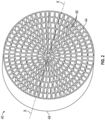
FIG. 2 is a perspective view of a water separator according to an embodiment; -
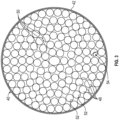
FIG. 3 is a plan view of a water separator according to another embodiment; and -
FIG. 4 is a perspective view of the water separator ofFIG. 3 according to an embodiment. - A detailed description of one or more embodiments of the disclosed apparatus and method are presented herein by way of exemplification and not limitation with reference to the Figures.
- With reference now to the
FIG. 1 , an exemplary portion of anenvironmental control system 20, such as part of a pack of an environmental control system for example, is illustrated. As shown, the environmental control system (ECS)pack 20 includes anair cycle machine 22 having aturbine 24, and in some embodiments includes one or more other components, such as acompressor 26 and afan 28 operably coupled to theturbine 24 by arotatable shaft 30 for example. In the illustrated, non-limiting embodiment, awater separator 32 and a water collector 34 arranged in series are located downstream from, and in some embodiments directly downstream from the outlet of theturbine 24. However, it should be understood that embodiments where thewater separator 32 and water collector 34 in combination are arranged downstream from any suitable component of theECS 20 are also contemplated herein. In an embodiment, thewater separator 32 is positioned within theECS 20 to receive a flow of medium, such as a fluid or air A for example, that is cool and has condensed water vapor entrained or suspended therein resulting in a fog-like consistency. - In the illustrated, non-limiting embodiment, the cool, dry medium output from the water collector 34 is provided to a
second turbine 36. Although thesecond turbine 36 is illustrated as being arranged directly downstream from the water collector 34, it should be appreciated that in other embodiments, one or more additional components may be arranged between the outlet of the water collector 34 and thesecond turbine 36. Further, although theturbine 36 is illustrated as being part of theair cycle machine 22, embodiments where theturbine 36 is separate from theair cycle machine 22 are also within the scope of the disclosure. - With reference now to
FIGS. 2-4 , various non-limiting embodiments of awater separator 40, such aswater separator 32 for example, are shown in more detail. In the illustrated, non-limiting embodiments, thewater separator 40 is an insert positionable within a duct or conduit 42 (seeFIG. 3 ) connected to a component of an environmental control system. Thewater separator 40 may be arranged within theduct 42 at any suitable location, such as downstream from the an outlet of theturbine 24 and upstream from the inlet of thewater collector 40. In embodiments where thewater separator 40 is an insert, thewater separator 40 may be permanently or removably mountable within the interior of theduct 42, or to a portion of theturbine 24. Alternatively, thewater separator 40 may be integrally formed with theduct 42 or the outlet of theturbine 24, such as via an additive manufacturing process for example. - In the illustrated, non-limiting embodiment, the
water separator 40 has a body that is generally cylindrical in shape. However, it should be understood that embodiments where a cross-section of thewater separator 40 is a shape other than a circle, such as a square, rectangle, triangle, or other suitable shape are also contemplated herein. In an embodiment, the shape and size of at least a portion of thewater separator 40 is complementary to or substantially identical to the interior surface of theduct 42. For example, an outer diameter of the firstupstream end 44 of thewater separator 40 may substantially equal to the inner diameter of theduct 42. Accordingly, when thewater separator 40 is arranged at an interior of theduct 42, a minimal amount of the medium, and in some embodiments, none of the medium, is configured to flow between the exterior of thewater separator 40 and the interior surface of theduct 42. - As shown, the
water separator 40 includes a plurality of fluidlydistinct flow channels 46 extending between the firstupstream end 44 of thewater separator 40 and a second,downstream end 48 of thewater separator 40. The plurality offlow channels 46 may be any suitable shape and are configured to minimize the pressure drop of the flow of medium as it passes therethrough, increase the efficiency of the flow of medium, or some combination thereof. As shown inFIG. 2 , theflow channels 46 may be formed by the intersection of a plurality of circular lines and a plurality of straight lines, resulting inflow channels 46 that are generally trapezoidal or triangular in shape. In the non-limiting embodiment ofFIGS. 3 and4 , theflow channels 46 have a generally rounded contour, such as a circular configuration for example. Accordingly, it should be understood that aflow channel 46 having any shape is within the scope of the disclosure. Although the firstupstream end 44 of each of theflow channels 46 is illustrated as being generally uniform in size and/or shape inFIGS. 3 and4 , or in other embodiments, the size and/or shape of the firstupstream end 44 of theflow channels 46 may vary betweenadjacent flow channels 46 as shown inFIG. 2 . - Further, the size and/or shape of each
flow channel 46 may be generally constant over the axial length of thewater separator 40, or alternatively, may vary between the firstupstream end 44 and the seconddownstream end 48 thereof. For example, one or more of theflow channels 46 may increase or decrease in size over the length of thewater separator 40. In embodiments where at least one of the size and shape of aflow channel 46 varies, it should be understood that the variation betweenadjacent flow channels 46 may be the same or may be different. In an embodiment, theclearance 50 betweenadjacent flow channels 46, such as represented by the gaps between thecircular flow channels 46 inFIGS. 3 and4 for example, may vary over the length of thewater separator 40. In an embodiment, theclearance 50 between theflow channels 46 is greater at the firstupstream end 44 than at the seconddownstream end 48. Such a reduction may, but need not be gradual over the length of thewater separator 40. As a result of this reduction inclearance 50, the outer diameter of thewater separator 40 at the seconddownstream end 48 may be less at the firstupstream end 44. Further, although theclearance 50 is illustrated and described herein as decreasing from the firstupstream end 44 towards the seconddownstream end 48, embodiments where theclearance 50 increases from the firstupstream end 44 towards the seconddownstream end 48 are also contemplated herein - The
interior surface 52 of eachflow channel 46 may be substantially smooth. In other embodiments, at least a portion of theinterior surface 52 of one or more of theflow channels 46 may be textured or roughened. Inclusion of such texture may increase the overall surface area of theinterior surface 52 of theflow channel 46 at that region. - In some embodiments, one or more of the
flow channels 46 has a substantially axial configuration (FIG. 2 ) that extends generally parallel to the longitudinal axis of the water separator. As a result, the flow of medium A is configured to flow axially between the first and second ends 44, 48 of thewater separator 40. In other embodiments, a swirl may be imparted to the medium within one or more of theflow channels 46 of thewater separator 40. In an embodiment, a swirl-inducinginsert 54, such as a turbulator having one or more coalescing features that extend into and interrupt the flow of medium, may be arranged within aflow channel 46, thereby causing the flow to swirl within theflow channel 46. - Alternatively, or in addition, at least one of the
flow channels 46 is configured to wrap about the longitudinal axis X of thewater separator 40 in a spiral-like configuration. In such embodiments, the flow of medium within theflow channel 46 is configured to spin or swirl about the axis X of thewater separator 40. The direction of the spiral of the at least oneflow channel 46 may be the same as the spin acting on the medium output from theturbine 24, or alternatively, may be in opposite the direction of the spin acting on the medium output from theturbine 24. In embodiments where a plurality of theflow channels 46 have a spiral-like configuration, it should be appreciated that the circumferential distance of the spiral about the central axis X applied to flowchannels 46 may vary, such as based on the position of theflow channel 46 relative to the insert (such as closed to the center vs. the outer periphery). - In an embodiment, to ensure that a minimum amount of swirl is applied to the flow passing through the
flow channels 46 having a spiral-like configuration, the firstupstream end 44 of one or more of theflow channels 46 of thewater separator 40 may be blocked to restrict or prevent flow therethrough. However, it should be understood that a firstupstream end 44 of one or more of theflow channels 46 may be blocked to control a flow through thewater separator 40 even in embodiments where none of theflow channels 46 have a spiral-like configuration. - In operation, as the flow of medium A output from a component, such as the
turbine 24 for example, passes through the plurality offlow channels 46 of thewater separator 40 in parallel, moisture within the flow of medium will coalesce in the form of droplets on theinterior surface 52 of theflow channels 46. As a result, a flow of drier medium A will be arranged at the center of eachflow channel 46. During this coalescing, the flow of medium A will cause these droplets formed on the interior surface of theflow channels 46 to move through theflow channels 46 for collection within the water collector 34 positioned directly downstream from thewater separator 40. The water collector 34 may be a conventional water collector as is known in the art. - A
water separator 40 as illustrated and described herein facilitates, and in some embodiments maximizes, the separation of water from an airflow within a small sizing envelope. As a result, the overall packaging of the ECS pack may be reduced, and the pressure drop of the medium within the water separator may be minimized. Thewater separator 40 may be particularly useful for removing water from an airflow when the water is in the form or a mist or fog, such as may be received from an outlet of a turbine. Further, by using thewater separator 40 in anECS pack 20 having twoturbines first turbine 24 may be configured to maintain the temperature of the medium A above freezing, whereas thesecond turbine 36 may be configured to achieve a necessary pressure and/or temperature of the medium to be provided to a load. - The term "about" is intended to include the degree of error associated with measurement of the particular quantity based upon the equipment available at the time of filing the application.
- The terminology used herein is for the purpose of describing particular embodiments only and is not intended to be limiting of the present disclosure. As used herein, the singular forms "a", "an" and "the" are intended to include the plural forms as well, unless the context clearly indicates otherwise. It will be further understood that the terms "comprises" and/or "comprising," when used in this specification, specify the presence of stated features, integers, steps, operations, elements, and/or components, but do not preclude the presence or addition of one or more other features, integers, steps, operations, element components, and/or groups thereof.
- While the present disclosure has been described with reference to an exemplary embodiment or embodiments, it will be understood by those skilled in the art that various changes may be made and equivalents may be substituted for elements thereof without departing from the scope of the present disclosure. In addition, many modifications may be made to adapt a particular situation or material to the teachings of the present disclosure without departing from the essential scope thereof. Therefore, it is intended that the present disclosure not be limited to the particular embodiment disclosed as the best mode contemplated for carrying out this present disclosure, but that the present disclosure will include all embodiments falling within the scope of the claims.
Claims (15)
- A water separator (32) for use in an environmental control system (20) of an aircraft comprising:
a body having a first upstream end (44), a second downstream end (48), and plurality of fluidly distinct flow channels (46) extending between the first upstream end and the second downstream end, wherein a flow of medium provided to the water separator is configured to flow through the plurality of fluidly distinct flow channels in parallel. - The water separator of claim 1, wherein an interior surface of a region of at least one of the plurality of fluidly distinct flow channels (46) is textured; and optionally wherein a surface area at the region is increased relative to the surface area at another region of the at least one of the plurality of fluidly distinct flow channels (46) that is not textured.
- The water separator of claim 1 or 2, wherein at least one of the plurality of fluidly distinct flow channels (46) has a spiral-like configuration about a longitudinal axis of the body.
- The water separator of claim 3, wherein a direction of the spiral-like configuration about the longitudinal axis and the direction of a spin of the flow of medium provided to the water separator (32) is the same; or wherein a direction of the spiral-like configuration about the longitudinal axis and the direction of a spin of the flow of medium provided to the water separator is different.
- The water separator of any preceding claim, wherein a configuration of each of the plurality of fluidly distinct flow channels (46) is substantially identical; or wherein a configuration of each of the plurality of fluidly distinct flow channels varies.
- The water separator of claims 1 to 4, wherein a configuration of at least one of the plurality of fluidly distinct flow channels (46) is constant between the first upstream end (44) and the second downstream end (48); or wherein a configuration of at least one of the plurality of fluidly distinct flow channels varies between the first upstream end and the second downstream end.
- The water separator of any preceding claim, wherein a clearance is defined between the plurality of fluidly distinct flow channels (46), and the clearance varies between the first upstream end (44) and the second downstream end (48).
- The water separator of any preceding claim, wherein an outer diameter of the body varies between the first upstream end (44) and the second downstream end (48).
- The water separator of any preceding claim, further comprising a swirl-inducing insert (54) arranged within at least one of the plurality of fluidly distinct flow channels (46).
- An environmental control system (20) comprising:a turbine (36) configured to extract energy and heat from a medium; anda water separator (32) arranged directly downstream from the turbine, the water separator including a body having a first upstream end (44), a second downstream end (48), and plurality of fluidly distinct flow channels (46) extending between the first upstream end and the second downstream end, wherein the medium provided to the water separator is configured to flow through the plurality of fluidly distinct flow channels in parallel.
- The environmental control system of claim 10, further comprising a duct extending from an outlet of the turbine (36), wherein the water separator (32) is positioned within the duct and an outer diameter of the water separator is equal to an inner diameter of the duct.
- The environmental control system of claim 11, wherein the water separator (32) is permanently affixed to the duct; or wherein the water separator (32) is removably mounted to the duct.
- The environmental control system of claim 10, 11 or 12, wherein the water separator (32) is configured to impart a swirl to the medium within at least one of the plurality of fluidly distinct flow channels (46).
- The environmental control system of any of claims 10 to 13, wherein an interior surface of a region of at least one of the plurality of fluidly distinct flow channels (46) is textured and a surface area at the region is increased relative to the surface area at another region of the at least one of the plurality of fluidly distinct flow channels that is not textured.
- The environmental control system of any of claims 10 to 14, further comprising a water collector (34) arranged downstream from and in fluid communication with the water separator (32).
Applications Claiming Priority (1)
| Application Number | Priority Date | Filing Date | Title |
|---|---|---|---|
| US17/880,355 US12311300B2 (en) | 2022-08-03 | 2022-08-03 | Mid-pressure water separation for environmental control system |
Publications (2)
| Publication Number | Publication Date |
|---|---|
| EP4316988A1 true EP4316988A1 (en) | 2024-02-07 |
| EP4316988B1 EP4316988B1 (en) | 2025-12-03 |
Family
ID=87553517
Family Applications (1)
| Application Number | Title | Priority Date | Filing Date |
|---|---|---|---|
| EP23188997.3A Active EP4316988B1 (en) | 2022-08-03 | 2023-08-01 | Mid-pressure water separation for environmental control system |
Country Status (2)
| Country | Link |
|---|---|
| US (1) | US12311300B2 (en) |
| EP (1) | EP4316988B1 (en) |
Cited By (3)
| Publication number | Priority date | Publication date | Assignee | Title |
|---|---|---|---|---|
| EP4596081A1 (en) * | 2024-02-02 | 2025-08-06 | Hamilton Sundstrand Corporation | Mid-pressure water separation for environmental control system |
| EP4656268A1 (en) * | 2024-05-28 | 2025-12-03 | Hamilton Sundstrand Corporation | Architected lattice of lattice coalescer |
| EP4699935A1 (en) * | 2024-08-20 | 2026-02-25 | Hamilton Sundstrand Corporation | Rotating fog harp coalescer |
Citations (7)
| Publication number | Priority date | Publication date | Assignee | Title |
|---|---|---|---|---|
| FR2594046A1 (en) * | 1986-02-13 | 1987-08-14 | United Technologies Corp | WATER COLLECTION APPARATUS FROM AN AIR CURRENT FLOWING IN A DUCT, IN PARTICULAR FOR AN AIR CONDITIONING INSTALLATION. |
| US7837752B2 (en) * | 2007-12-03 | 2010-11-23 | Honeywell International Inc. | Water removal downstream of a turbine |
| US20150090119A1 (en) * | 2013-10-01 | 2015-04-02 | Honeywell International Inc. | Self-contained aircraft electronic air treatment system |
| US20170045243A1 (en) * | 2015-08-14 | 2017-02-16 | Honeywell International Inc. | Water extractor device using scuppers |
| US20190366251A1 (en) * | 2017-01-13 | 2019-12-05 | W.O.M. World Of Medicine Gmbh | Device for the separation of flue gas particles in laparoscopy |
| US10697328B2 (en) * | 2017-09-13 | 2020-06-30 | General Electric Company | Device and method for removing particles from air flow |
| EP4201814A1 (en) * | 2021-12-22 | 2023-06-28 | Hamilton Sundstrand Corporation | Multistage swirler for environmental control system |
Family Cites Families (52)
| Publication number | Priority date | Publication date | Assignee | Title |
|---|---|---|---|---|
| US1678844A (en) * | 1924-05-31 | 1928-07-31 | Blaw Knox Co | Fluid separator |
| US2485522A (en) * | 1945-09-04 | 1949-10-18 | Garrett Corp Aires Mfg Company | Humidity control in aircraft air conditioning |
| GB671567A (en) * | 1949-02-04 | 1952-05-07 | Garrett Corp | Improvements in or relating to a device for conveying refrigerated air through a duct |
| US2819590A (en) * | 1953-08-21 | 1958-01-14 | Garrett Corp | Ventilated suit refrigeration unit |
| US2835340A (en) | 1955-02-17 | 1958-05-20 | United Aircraft Corp | Moisture separator |
| US3208234A (en) * | 1963-03-01 | 1965-09-28 | Lockheed Aircraft Corp | Air cycle refrigeration system and method |
| US3405511A (en) * | 1966-05-16 | 1968-10-15 | Burgess Manning Co | Vane type separator |
| US3355905A (en) | 1966-08-19 | 1967-12-05 | Garrett Corp | Air conditioning system with means for preventing the formation of ice |
| US3520114A (en) * | 1968-06-28 | 1970-07-14 | Pall Corp | Vortex air cleaner assembly having uniform particle removal efficiency throughout the array of air cleaners |
| DE2148079B2 (en) * | 1971-09-27 | 1976-11-04 | Regehr, Ulrich, Dr.-Ing., 5100 Aachen | DEVICE FOR SEPARATING LIQUID DROPS |
| US3877245A (en) * | 1973-11-30 | 1975-04-15 | Rovac Corp | Air conditioner having tempering and moisture control means |
| US3884660A (en) * | 1973-12-07 | 1975-05-20 | Perry Equipment Corp | Gas-liquid separator |
| DE2619688C3 (en) * | 1976-05-04 | 1984-11-15 | Ulrich Dr.-Ing. 5100 Aachen Regehr | Device for separating liquid droplets |
| US4158449A (en) * | 1976-12-07 | 1979-06-19 | Pall Corporation | Inlet air cleaner assembly for turbine engines |
| US4162906A (en) * | 1977-05-05 | 1979-07-31 | Donaldson Company, Inc. | Side outlet tube |
| US4255174A (en) * | 1978-11-28 | 1981-03-10 | Rolls-Royce Limited | Separator |
| US4352273A (en) * | 1979-05-22 | 1982-10-05 | The Garrett Corporation | Fluid conditioning apparatus and system |
| US4537608A (en) * | 1983-11-16 | 1985-08-27 | Pall Corporation | System for removing contaminant particles from a gas |
| US4602925A (en) * | 1984-12-27 | 1986-07-29 | Westinghouse Electric Corp. | Moisture separator |
| US4783204A (en) * | 1986-08-05 | 1988-11-08 | Westinghouse Electric Corp. | Apparatus and method for drying steam |
| DE3627555C1 (en) * | 1986-08-14 | 1987-08-06 | Dieter Prof Dr-Ing Wurz | Liquid separator |
| WO1991012990A1 (en) * | 1990-02-20 | 1991-09-05 | Allied-Signal Inc. | Fluid conditioning apparatus and system |
| US5214935A (en) * | 1990-02-20 | 1993-06-01 | Allied-Signal Inc. | Fluid conditioning apparatus and system |
| US5025642A (en) * | 1990-02-20 | 1991-06-25 | Allied-Signal Inc. | Fluid conditioning apparatus and system |
| IL114613A (en) * | 1995-07-16 | 1999-09-22 | Tat Ind Ltd | Parallel flow condenser heat exchanger |
| US5885333A (en) * | 1996-01-17 | 1999-03-23 | General Electric Company | Low pressure drop steam separators |
| JP3816289B2 (en) * | 2000-02-18 | 2006-08-30 | ナブテスコ株式会社 | Hollow fiber membrane dehumidifier |
| US6257003B1 (en) * | 2000-08-04 | 2001-07-10 | Hamilton Sundstrand Corporation | Environmental control system utilizing two air cycle machines |
| JP2002126429A (en) * | 2000-10-20 | 2002-05-08 | Mitsubishi Heavy Ind Ltd | Moisture separator |
| US6460353B2 (en) * | 2001-03-02 | 2002-10-08 | Honeywell International Inc. | Method and apparatus for improved aircraft environmental control system utilizing parallel heat exchanger arrays |
| DE10142701A1 (en) * | 2001-08-31 | 2003-04-03 | Mann & Hummel Filter | Multi-cell cyclone and process for its production |
| JP2003144824A (en) * | 2001-11-06 | 2003-05-20 | Mitsubishi Heavy Ind Ltd | Moisture separator and steam generator |
| US6637215B1 (en) * | 2002-10-16 | 2003-10-28 | Honeywell International, Inc. | Aircraft ground support air conditioning unit with heat exchanger bypass |
| EP1747054B1 (en) * | 2004-03-08 | 2008-07-02 | Reinz-Dichtungs-Gmbh | A fluid separation device |
| DE102004036568A1 (en) * | 2004-07-28 | 2006-02-16 | Liebherr-Aerospace Lindenberg Gmbh | Water separator for air conditioners |
| GB2427682B (en) * | 2005-03-18 | 2009-08-05 | Honeywell Normalair Garrett | Apparatus for extracting condensate |
| US7779644B2 (en) * | 2006-07-31 | 2010-08-24 | Hamilton Sundstrand Corporation | Air cycle machine for an aircraft environmental control system |
| US20100326025A1 (en) * | 2009-06-24 | 2010-12-30 | Rodney Allan Bratton | Vane-type separator |
| EP2811227B1 (en) * | 2013-06-06 | 2018-03-28 | General Electric Technology GmbH | Moisture separator configuration |
| NO341179B1 (en) * | 2015-08-28 | 2017-09-04 | Fjords Proc As | Axial flow demister |
| US10265651B2 (en) * | 2016-11-14 | 2019-04-23 | Hamilton Sundstrand Corporation | Compact water extractor |
| US10960332B2 (en) * | 2017-10-09 | 2021-03-30 | Honeywell International Inc. | High pressure water extraction device with shave off edge that feeds a low pressure chamber and internal helix feature to improve water collection and drainage |
| US10765982B2 (en) * | 2018-06-26 | 2020-09-08 | Hamilton Sundstrand Corporation | Helical water collector |
| US11154804B2 (en) * | 2018-12-07 | 2021-10-26 | Hamilton Sundstrand Corporation | Water extractors and methods of making water extractors |
| US11525618B2 (en) * | 2019-10-04 | 2022-12-13 | Hamilton Sundstrand Corporation | Enhanced heat exchanger performance under frosting conditions |
| US11278964B2 (en) * | 2019-10-10 | 2022-03-22 | The Boeing Company | Monolithic particle separators |
| EP3944888B1 (en) * | 2020-07-29 | 2026-04-08 | Hamilton Sundstrand Corporation | High-pressure annular water collector with axial swirl vanes for an air cycle environmental control system |
| US12172758B2 (en) * | 2020-10-13 | 2024-12-24 | General Electric Company | System and method for cooling aircraft components |
| US11485499B2 (en) * | 2020-10-13 | 2022-11-01 | General Electric Company | System and method for cooling aircraft components |
| US12065251B2 (en) * | 2021-06-29 | 2024-08-20 | Hamilton Sundstrand Corporation | Centrifugal water collector with conical water scupper |
| US12331971B2 (en) * | 2021-09-10 | 2025-06-17 | Hamilton Sundstrand Corporation | Integrated mid-pressure water separator |
| US12084188B2 (en) * | 2021-11-30 | 2024-09-10 | Hamilton Sundstrand Corporation | Mid-pressure water collector for environmental control system |
-
2022
- 2022-08-03 US US17/880,355 patent/US12311300B2/en active Active
-
2023
- 2023-08-01 EP EP23188997.3A patent/EP4316988B1/en active Active
Patent Citations (7)
| Publication number | Priority date | Publication date | Assignee | Title |
|---|---|---|---|---|
| FR2594046A1 (en) * | 1986-02-13 | 1987-08-14 | United Technologies Corp | WATER COLLECTION APPARATUS FROM AN AIR CURRENT FLOWING IN A DUCT, IN PARTICULAR FOR AN AIR CONDITIONING INSTALLATION. |
| US7837752B2 (en) * | 2007-12-03 | 2010-11-23 | Honeywell International Inc. | Water removal downstream of a turbine |
| US20150090119A1 (en) * | 2013-10-01 | 2015-04-02 | Honeywell International Inc. | Self-contained aircraft electronic air treatment system |
| US20170045243A1 (en) * | 2015-08-14 | 2017-02-16 | Honeywell International Inc. | Water extractor device using scuppers |
| US20190366251A1 (en) * | 2017-01-13 | 2019-12-05 | W.O.M. World Of Medicine Gmbh | Device for the separation of flue gas particles in laparoscopy |
| US10697328B2 (en) * | 2017-09-13 | 2020-06-30 | General Electric Company | Device and method for removing particles from air flow |
| EP4201814A1 (en) * | 2021-12-22 | 2023-06-28 | Hamilton Sundstrand Corporation | Multistage swirler for environmental control system |
Cited By (3)
| Publication number | Priority date | Publication date | Assignee | Title |
|---|---|---|---|---|
| EP4596081A1 (en) * | 2024-02-02 | 2025-08-06 | Hamilton Sundstrand Corporation | Mid-pressure water separation for environmental control system |
| EP4656268A1 (en) * | 2024-05-28 | 2025-12-03 | Hamilton Sundstrand Corporation | Architected lattice of lattice coalescer |
| EP4699935A1 (en) * | 2024-08-20 | 2026-02-25 | Hamilton Sundstrand Corporation | Rotating fog harp coalescer |
Also Published As
| Publication number | Publication date |
|---|---|
| US20240042360A1 (en) | 2024-02-08 |
| EP4316988B1 (en) | 2025-12-03 |
| US12311300B2 (en) | 2025-05-27 |
Similar Documents
| Publication | Publication Date | Title |
|---|---|---|
| EP4316988B1 (en) | Mid-pressure water separation for environmental control system | |
| EP3412354B1 (en) | Tangential entry water separator for aircraft ecs | |
| EP3427812B1 (en) | Water extractor for environmental control system of an aircraft | |
| EP1087888B1 (en) | Coanda water extractor | |
| EP3586938B1 (en) | Helical water collector | |
| US20240359800A1 (en) | Centrifugal water collector with conical water scupper | |
| US12115479B2 (en) | High-pressure annular water collector with axial swirl vanes for an air cycle environmental control system | |
| EP4147765A1 (en) | Integrated mid-pressure water separator | |
| EP4201814A1 (en) | Multistage swirler for environmental control system | |
| EP3620222B1 (en) | High pressure water collector with radial diffuser | |
| EP4534173A1 (en) | Mid-pressure water separation for environmental control system | |
| EP4588548A1 (en) | Mid-pressure water separation for environmental control system | |
| US11780592B2 (en) | Environmental control system pack | |
| EP4596080A1 (en) | Mid-pressure water separation for environmental control system | |
| EP4596081A1 (en) | Mid-pressure water separation for environmental control system | |
| US20260054206A1 (en) | Radial flow mid-pressure water separation for environmental control system | |
| EP4268928A2 (en) | Mid-pressure water collector (mpwc) with helical flow channel and radial scuppers | |
| EP4699935A1 (en) | Rotating fog harp coalescer |
Legal Events
| Date | Code | Title | Description |
|---|---|---|---|
| PUAI | Public reference made under article 153(3) epc to a published international application that has entered the european phase |
Free format text: ORIGINAL CODE: 0009012 |
|
| STAA | Information on the status of an ep patent application or granted ep patent |
Free format text: STATUS: THE APPLICATION HAS BEEN PUBLISHED |
|
| AK | Designated contracting states |
Kind code of ref document: A1 Designated state(s): AL AT BE BG CH CY CZ DE DK EE ES FI FR GB GR HR HU IE IS IT LI LT LU LV MC ME MK MT NL NO PL PT RO RS SE SI SK SM TR |
|
| STAA | Information on the status of an ep patent application or granted ep patent |
Free format text: STATUS: REQUEST FOR EXAMINATION WAS MADE |
|
| 17P | Request for examination filed |
Effective date: 20240807 |
|
| RBV | Designated contracting states (corrected) |
Designated state(s): AL AT BE BG CH CY CZ DE DK EE ES FI FR GB GR HR HU IE IS IT LI LT LU LV MC ME MK MT NL NO PL PT RO RS SE SI SK SM TR |
|
| GRAP | Despatch of communication of intention to grant a patent |
Free format text: ORIGINAL CODE: EPIDOSNIGR1 |
|
| STAA | Information on the status of an ep patent application or granted ep patent |
Free format text: STATUS: GRANT OF PATENT IS INTENDED |
|
| RIC1 | Information provided on ipc code assigned before grant |
Ipc: B64D 13/06 20060101AFI20250610BHEP |
|
| INTG | Intention to grant announced |
Effective date: 20250704 |
|
| GRAS | Grant fee paid |
Free format text: ORIGINAL CODE: EPIDOSNIGR3 |
|
| GRAA | (expected) grant |
Free format text: ORIGINAL CODE: 0009210 |
|
| STAA | Information on the status of an ep patent application or granted ep patent |
Free format text: STATUS: THE PATENT HAS BEEN GRANTED |
|
| AK | Designated contracting states |
Kind code of ref document: B1 Designated state(s): AL AT BE BG CH CY CZ DE DK EE ES FI FR GB GR HR HU IE IS IT LI LT LU LV MC ME MK MT NL NO PL PT RO RS SE SI SK SM TR |
|
| REG | Reference to a national code |
Ref country code: CH Ref legal event code: F10 Free format text: ST27 STATUS EVENT CODE: U-0-0-F10-F00 (AS PROVIDED BY THE NATIONAL OFFICE) Effective date: 20251203 Ref country code: GB Ref legal event code: FG4D |
|
| REG | Reference to a national code |
Ref country code: DE Ref legal event code: R096 Ref document number: 602023009193 Country of ref document: DE |
|
| REG | Reference to a national code |
Ref country code: IE Ref legal event code: FG4D |
|
| REG | Reference to a national code |
Ref country code: NL Ref legal event code: MP Effective date: 20251203 |
|
| PG25 | Lapsed in a contracting state [announced via postgrant information from national office to epo] |
Ref country code: ES Free format text: LAPSE BECAUSE OF FAILURE TO SUBMIT A TRANSLATION OF THE DESCRIPTION OR TO PAY THE FEE WITHIN THE PRESCRIBED TIME-LIMIT Effective date: 20251203 |
|
| REG | Reference to a national code |
Ref country code: LT Ref legal event code: MG9D |
|
| PG25 | Lapsed in a contracting state [announced via postgrant information from national office to epo] |
Ref country code: NO Free format text: LAPSE BECAUSE OF FAILURE TO SUBMIT A TRANSLATION OF THE DESCRIPTION OR TO PAY THE FEE WITHIN THE PRESCRIBED TIME-LIMIT Effective date: 20260303 |
|
| PG25 | Lapsed in a contracting state [announced via postgrant information from national office to epo] |
Ref country code: FI Free format text: LAPSE BECAUSE OF FAILURE TO SUBMIT A TRANSLATION OF THE DESCRIPTION OR TO PAY THE FEE WITHIN THE PRESCRIBED TIME-LIMIT Effective date: 20251203 Ref country code: HR Free format text: LAPSE BECAUSE OF FAILURE TO SUBMIT A TRANSLATION OF THE DESCRIPTION OR TO PAY THE FEE WITHIN THE PRESCRIBED TIME-LIMIT Effective date: 20251203 |
|
| PG25 | Lapsed in a contracting state [announced via postgrant information from national office to epo] |
Ref country code: RS Free format text: LAPSE BECAUSE OF FAILURE TO SUBMIT A TRANSLATION OF THE DESCRIPTION OR TO PAY THE FEE WITHIN THE PRESCRIBED TIME-LIMIT Effective date: 20260303 |
|
| PG25 | Lapsed in a contracting state [announced via postgrant information from national office to epo] |
Ref country code: PL Free format text: LAPSE BECAUSE OF FAILURE TO SUBMIT A TRANSLATION OF THE DESCRIPTION OR TO PAY THE FEE WITHIN THE PRESCRIBED TIME-LIMIT Effective date: 20251203 |
|
| PG25 | Lapsed in a contracting state [announced via postgrant information from national office to epo] |
Ref country code: LV Free format text: LAPSE BECAUSE OF FAILURE TO SUBMIT A TRANSLATION OF THE DESCRIPTION OR TO PAY THE FEE WITHIN THE PRESCRIBED TIME-LIMIT Effective date: 20251203 |
|
| PG25 | Lapsed in a contracting state [announced via postgrant information from national office to epo] |
Ref country code: BG Free format text: LAPSE BECAUSE OF FAILURE TO SUBMIT A TRANSLATION OF THE DESCRIPTION OR TO PAY THE FEE WITHIN THE PRESCRIBED TIME-LIMIT Effective date: 20251203 |