EP4316961A1 - Vehicle - Google Patents
Vehicle Download PDFInfo
- Publication number
- EP4316961A1 EP4316961A1 EP22779634.9A EP22779634A EP4316961A1 EP 4316961 A1 EP4316961 A1 EP 4316961A1 EP 22779634 A EP22779634 A EP 22779634A EP 4316961 A1 EP4316961 A1 EP 4316961A1
- Authority
- EP
- European Patent Office
- Prior art keywords
- vehicle
- communication unit
- vehicle body
- seat
- control device
- Prior art date
- Legal status (The legal status is an assumption and is not a legal conclusion. Google has not performed a legal analysis and makes no representation as to the accuracy of the status listed.)
- Pending
Links
Images




Classifications
-
- B—PERFORMING OPERATIONS; TRANSPORTING
- B62—LAND VEHICLES FOR TRAVELLING OTHERWISE THAN ON RAILS
- B62J—CYCLE SADDLES OR SEATS; AUXILIARY DEVICES OR ACCESSORIES SPECIALLY ADAPTED TO CYCLES AND NOT OTHERWISE PROVIDED FOR, e.g. ARTICLE CARRIERS OR CYCLE PROTECTORS
- B62J43/00—Arrangements of batteries
- B62J43/30—Arrangements of batteries for providing power to equipment other than for propulsion
-
- B—PERFORMING OPERATIONS; TRANSPORTING
- B60—VEHICLES IN GENERAL
- B60R—VEHICLES, VEHICLE FITTINGS, OR VEHICLE PARTS, NOT OTHERWISE PROVIDED FOR
- B60R25/00—Fittings or systems for preventing or indicating unauthorised use or theft of vehicles
- B60R25/01—Fittings or systems for preventing or indicating unauthorised use or theft of vehicles operating on vehicle systems or fittings, e.g. on doors, seats or windscreens
- B60R25/02—Fittings or systems for preventing or indicating unauthorised use or theft of vehicles operating on vehicle systems or fittings, e.g. on doors, seats or windscreens operating on the steering mechanism
-
- B—PERFORMING OPERATIONS; TRANSPORTING
- B60—VEHICLES IN GENERAL
- B60R—VEHICLES, VEHICLE FITTINGS, OR VEHICLE PARTS, NOT OTHERWISE PROVIDED FOR
- B60R25/00—Fittings or systems for preventing or indicating unauthorised use or theft of vehicles
- B60R25/20—Means to switch the anti-theft system on or off
- B60R25/24—Means to switch the anti-theft system on or off using electronic identifiers containing a code not memorised by the user
-
- B—PERFORMING OPERATIONS; TRANSPORTING
- B62—LAND VEHICLES FOR TRAVELLING OTHERWISE THAN ON RAILS
- B62H—CYCLE STANDS; SUPPORTS OR HOLDERS FOR PARKING OR STORING CYCLES; APPLIANCES PREVENTING OR INDICATING UNAUTHORIZED USE OR THEFT OF CYCLES; LOCKS INTEGRAL WITH CYCLES; DEVICES FOR LEARNING TO RIDE CYCLES
- B62H5/00—Appliances preventing or indicating unauthorised use or theft of cycles; Locks integral with cycles
- B62H5/02—Appliances preventing or indicating unauthorised use or theft of cycles; Locks integral with cycles for locking the steering mechanism
-
- B—PERFORMING OPERATIONS; TRANSPORTING
- B62—LAND VEHICLES FOR TRAVELLING OTHERWISE THAN ON RAILS
- B62J—CYCLE SADDLES OR SEATS; AUXILIARY DEVICES OR ACCESSORIES SPECIALLY ADAPTED TO CYCLES AND NOT OTHERWISE PROVIDED FOR, e.g. ARTICLE CARRIERS OR CYCLE PROTECTORS
- B62J45/00—Electrical equipment arrangements specially adapted for use as accessories on cycles, not otherwise provided for
-
- B—PERFORMING OPERATIONS; TRANSPORTING
- B62—LAND VEHICLES FOR TRAVELLING OTHERWISE THAN ON RAILS
- B62K—CYCLES; CYCLE FRAMES; CYCLE STEERING DEVICES; RIDER-OPERATED TERMINAL CONTROLS SPECIALLY ADAPTED FOR CYCLES; CYCLE AXLE SUSPENSIONS; CYCLE SIDECARS, FORECARS, OR THE LIKE
- B62K11/00—Motorcycles, engine-assisted cycles or motor scooters with one or two wheels
- B62K11/02—Frames
- B62K11/04—Frames characterised by the engine being between front and rear wheels
-
- B—PERFORMING OPERATIONS; TRANSPORTING
- B60—VEHICLES IN GENERAL
- B60R—VEHICLES, VEHICLE FITTINGS, OR VEHICLE PARTS, NOT OTHERWISE PROVIDED FOR
- B60R2325/00—Indexing scheme relating to vehicle anti-theft devices
- B60R2325/30—Vehicles applying the vehicle anti-theft devices
- B60R2325/306—Motorcycles
-
- B—PERFORMING OPERATIONS; TRANSPORTING
- B62—LAND VEHICLES FOR TRAVELLING OTHERWISE THAN ON RAILS
- B62H—CYCLE STANDS; SUPPORTS OR HOLDERS FOR PARKING OR STORING CYCLES; APPLIANCES PREVENTING OR INDICATING UNAUTHORIZED USE OR THEFT OF CYCLES; LOCKS INTEGRAL WITH CYCLES; DEVICES FOR LEARNING TO RIDE CYCLES
- B62H5/00—Appliances preventing or indicating unauthorised use or theft of cycles; Locks integral with cycles
- B62H5/20—Appliances preventing or indicating unauthorised use or theft of cycles; Locks integral with cycles indicating unauthorised use, e.g. acting on signalling devices
-
- B—PERFORMING OPERATIONS; TRANSPORTING
- B62—LAND VEHICLES FOR TRAVELLING OTHERWISE THAN ON RAILS
- B62J—CYCLE SADDLES OR SEATS; AUXILIARY DEVICES OR ACCESSORIES SPECIALLY ADAPTED TO CYCLES AND NOT OTHERWISE PROVIDED FOR, e.g. ARTICLE CARRIERS OR CYCLE PROTECTORS
- B62J40/00—Arrangements of air cleaners specially adapted for cycles
Definitions
- the present invention relates to a vehicle.
- Patent Literature 2 a technique in which a control unit is provided under a rider's seat is disclosed (see, for example, Patent Literature 2).
- a conventional technique of providing in a vehicle an ECU including a vehicle unlocking unit for unlocking a handlebar lock module is disclosed.
- an ECU including a communication unit for unlocking a handlebar lock module in a vehicle it is required to secure stable communication by a communication unit and theft prevention.
- An object of the present invention is to provide a vehicle that secures both stable communication by an ECU including a communication unit that unlocks a handlebar lock module and theft prevention.
- a vehicle including a steering shaft, a vehicle body frame including a head pipe that turnably supports the steering shaft, a main frame that extends from the head pipe to a rear side of the vehicle, and a seat rail that is continuous with the main frame and disposed below a seat on which a rider of the vehicle is seated to fix the seat, and a drive device that generates power for the vehicle, includes a communication unit for communicating with a device external to the vehicle, where the communication unit is provided below and on an outer side in a vehicle width direction of the seat rail and in a space covered by and on an inner side of a vehicle body cover that protects a vehicle body part.
- a communication unit is provided below and on the outer side in the vehicle width direction of the seat rail and in a space covered by and on the inner side of a vehicle body cover that protects vehicle body parts, metal parts do not hinder communication by the communication unit, and stability of communication can be improved. Moreover, providing the communication unit in the space covered by and in the inner side of the vehicle body cover that protects vehicle body parts makes it difficult to remove the communication unit from the vehicle, which secures theft prevention.
- a reference sign FR denotes the front side of the vehicle body
- a reference sign UP denotes the upper side of the vehicle body
- a reference sign LH denotes the left side of the vehicle body.
- Fig. 1 is a side view illustrating a saddle-ride vehicle 10 according to an embodiment of the present invention.
- the saddle-ride vehicle 10 is a vehicle including a vehicle body frame 11, a power unit 12 supported by the vehicle body frame 11, a front fork 14 that supports a front wheel 13 in a steerable manner, a swing arm 16 that supports a rear wheel 15, and a seat 17 for a rider.
- the saddle-ride vehicle 10 is a vehicle on which the rider is seated astride the seat 17.
- the seat 17 is provided in the upper side of a rear part of the vehicle body frame 11.
- the vehicle body frame 11 includes a head pipe 18 provided at a front end portion of the vehicle body frame 11, a front frame 19 located rearward of the head pipe 18, and a rear frame 20 located rearward of the front frame 19. A front end portion of the front frame 19 is connected to the head pipe 18.
- the seat 17 is supported by the rear frame 20.
- the front fork 14 is supported by the head pipe 18 so as to be steerable to the left and the right.
- the front wheel 13 is supported by an axle 13a, which is provided at a lower end portion of the front fork 14.
- a steering handlebar 21 to be gripped by the rider is attached to an upper end portion of the front fork 14.
- the swing arm 16 is supported by a pivot shaft 22 supported by the vehicle body frame 11.
- the pivot shaft 22 is a shaft extending horizontally in the vehicle width direction.
- the pivot shaft 22 is inserted through a front end portion of the swing arm 16.
- the swing arm 16 swings up and down about the pivot shaft 22.
- the rear wheel 15 is supported by an axle 15a, which is provided at a rear end portion of the swing arm 16.
- the power unit 12 is disposed between the front wheel 13 and the rear wheel 15, and is supported by the vehicle body frame 11.
- the power unit 12 is an internal combustion engine.
- the power unit 12 includes a crankcase 23, and a cylinder portion 24 that houses a reciprocating piston.
- the cylinder portion 24 has an exhaust port to which an exhaust device 25 is connected.
- Output of the power unit 12 is transmitted to the rear wheel 15 by a drive force transmission member that connects the power unit 12 and the rear wheel 15.
- the saddle-ride vehicle 10 includes a front fender 26 that covers the front wheel 13 from the upper side, a rear fender 27 that covers the rear wheel 15 from the upper side, a step 28 on which the rider places his or her foot, and a fuel tank 29 for storing fuel to be used by the power unit 12.
- the front fender 26 is attached to the front fork 14.
- the rear fender 27 and the step 28 are provided below the seat 17.
- the fuel tank 29 is supported by the vehicle body frame 11.
- Fig. 2 is a block diagram illustrating a configuration of a control device.
- a control device 40 includes an ECU 41 as a control unit.
- the ECU 41 includes, for example, a processor such as a central processing unit (CPU) and a storage unit such as a random access memory (RAM) and a read only memory (ROM).
- a processor such as a central processing unit (CPU)
- a storage unit such as a random access memory (RAM) and a read only memory (ROM).
- the storage unit stores data such as an engine control program. Specifically, a processor of the ECU 41 executes a control program to control components of the vehicle.
- the ECU 41 is connected to a handlebar lock module 42.
- the handlebar lock module 42 is for locking the turning action of the handlebar during parking.
- the control device 40 includes a communication unit 44 that receives a signal from a smart key 43 as a device external to the vehicle and carried by the rider.
- the control device 40 includes a determination unit 45 that determines whether a signal from the smart key 43 received by the communication unit 44 is a signal for unlocking the handlebar lock module 42, and an unlocking unit 46 that unlocks the handlebar lock module 42 when determination is made that the signal from the smart key 43 is a signal for unlocking.
- a signal is transmitted from the smart key 43 to the ECU 41 via the communication unit 44 and the determination unit 45 of the ECU 41 determines whether the signal from the smart key 43 is a signal for unlocking.
- the unlocking unit 46 unlocks the handlebar lock module 42.
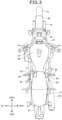
- Fig. 3 is a plan view of the vehicle body.
- Fig. 4 is a perspective view of the vehicle body as viewed from the right side.
- Fig. 5 is a cross-sectional view taken along line A-A in Fig. 1 .
- the rear frame 20 includes a seat rail 30 that supports the seat 17.
- Vehicle body parts such as an air cleaner 31 is housed in a space in the upper side of the rear frame 20 and below the seat rail 30.
- a side cover 32 as a vehicle body cover is attached on the outer side of the space demarcated by the seat rail 30 and the rear frame 20.
- an exhaust device 25 as an exhaust mechanism extending rearward and connected to the exhaust port of the power unit 12 is attached on the right side of the vehicle body frame 11.
- a battery 33 as an electric storage device is installed on a side opposite to the right side on which the exhaust device 25 of the vehicle is attached.
- control device 40 is installed on a side where the exhaust device 25 is provided and in a space demarcated by the seat rail 30 and the rear frame 20. In this state, the control device 40 is disposed further on the outer side than the seat rail 30 in the vehicle width direction and in the inner side of the side cover 32.
- the seat rail 30 made of metal may cause a communication failure.
- the control device 40 since the control device 40 is disposed on the outer side of the seat rail 30 and on the side where the exhaust device 25 is installed, that is, on the side opposite to the side where the battery 33 is installed, effects by the seat rail 30 made of metal causing communication failure and the battery 33 can be suppressed, and stable communication by the communication unit 44 of the control device 40 can be secured.
- the communication unit 44 may be disposed at the place where the control device 40 is disposed. By disposing the communication unit 44 in such a manner, there will be no chance of the communication unit 44 suffering communication failure caused by a metal part such as the seat rail 30.
- control device 40 on the side opposite to the side where there are many metal parts and where the battery 33 is provided in an easily detachable manner can improve stability of communication, and improve theft prevention without using additional parts.
- the control device 40 is fixed to the vehicle body frame 11. By fixing the control device 40 to the vehicle body frame 11 having high rigidity, assembling work can be performed stably, and work efficiency can be improved.
- the rider operates the smart key 43 to transmit a signal from the smart key 43 to the ECU 41 via the communication unit 44.
- the determination unit 45 of the ECU 41 determines whether the signal from the smart key 43 is a signal for unlocking, and when the determination unit 45 determines that the signal is for unlocking, the unlocking unit 46 unlocks the handlebar lock module 42.
- the handlebar lock module 42 is thereby unlocked, and now the handlebar can be turned.
- control device 40 is disposed in the space demarcated by the seat rail 30 and the rear frame 20 to be on the outer side of the seat rail 30 and on the inner side of the side cover 32, so that communication by the communication unit 44 of the control device 40 is not hindered by a metal part, and stability of communication can be improved.
- control device 40 in the space covered by and in the inner side of the side cover 32 that protects vehicle body parts makes it difficult to remove the control device 40 from the vehicle, and thus secures theft prevention. Furthermore, with the control device 40 provided on the side where the exhaust device 25 is installed, in case of accidental falling, the exhaust device 25 first hits to mitigate an impact on the control device 40. This improves impact resistance of the control device 40 against accidental falling without improving durability of the control device 40.
- fixing the control device 40 to the vehicle body frame 11 firmly fixes the control device 40 to improve impact resistance.
- the present embodiment includes the communication unit 44 for communicating with the smart key 43 (device external to the vehicle), and the communication unit 44 is provided in the space below and on the outer side in the vehicle width direction of the seat rail 30, and is covered by and on the inner side of the side cover 32 (vehicle body cover) that protects the vehicle body parts.
- the communication unit 44 is provided on a side, in the vehicle width direction, where the exhaust device 25 is provided, below and on the outer side in the vehicle width direction of the seat rail 30, and in a space covered by and on the inner side of the side cover 32 that protects the vehicle body parts, communication made by the communication unit 44 is not hindered by a metal part, and stable communication can be improved. Moreover, providing the communication unit 44 in the space covered by and in the inner side of the side cover 32 that protects the vehicle body parts makes it difficult to remove the communication unit 44 from the vehicle, and this secures theft prevention.
- the present embodiment includes the ECU 41 (control unit) that controls a device mounted on the vehicle, and the control device 40 including the communication unit 44 and the ECU 41.
- the control device 40 including the communication unit 44 is provided below and on the outer side in the vehicle width direction of the seat rail and in the space covered by and on the inner side of the side cover 32 that protects the vehicle body parts, so that stability of communication by the communication unit 44 can be improved. Moreover, providing the control device 40 in the space covered by and in the inner side of the side cover 32 that protects vehicle body parts makes it difficult to remove the control device 40 from the vehicle, and thus secures theft prevention.
- the vehicle includes the handlebar lock module 42 that locks turning of the steering shaft, and the ECU 41 (control unit) determines whether to unlock the handlebar lock module.
- control device 40 can unlock the handlebar lock module by the ECU 41 making determination to unlock the handlebar lock module.
- the present embodiment includes the exhaust device 25 (exhaust mechanism) for exhausting substances produced in a process of operating the power unit 12 (drive device) to the outside of the vehicle, and the communication unit 44 is provided on a side, in the vehicle width direction, where the exhaust device 25 is provided
- the exhaust device 25 With the communication unit 44 provided on the side where the exhaust device 25 is installed, in case of accidental falling, the exhaust device 25 first hits to mitigate an impact on the communication unit 44. This improves impact resistance of the communication unit 44 against falling without improving durability of the control device 40.
- the communication unit 44 is attached to the vehicle body frame 11.
- Fixing the communication unit 44 to the vehicle body frame 11 firmly fixes the communication unit 44 to improve impact resistance.
- the vehicle includes the battery 33 (electric storage device) for operating at least one electrical component provided in the vehicle, and the battery 33 is provided on a side opposite to, in the vehicle width direction with respect to the vehicle center as an axis, the side where the communication unit 44 is provided.
- the battery 33 electrical storage device
- Providing the communication unit 44 on the side opposite to the side where there are many metal parts and where the battery 33 is provided in an easily detachable manner can improve stability of communication and theft prevention without using additional parts.
- Fig. 6 is a cross-sectional view illustrating an exemplary modification of the present invention.
- a control device 40 including a communication unit 44 is attached to an inner surface of a side cover 32.
- control device 40 including the communication unit 44 attached to the inner surface of the side cover 32, vibration of the vehicle body can be absorbed by the side cover 32.
- the control device 40 including the communication unit 44 can be installed in the vehicle without improving vibration resistance of the control device 40 including the communication unit 44.
- Fig. 7 is a cross-sectional view illustrating another exemplary modification of the present invention.
- an air cleaner 31 for removing impurities from air taken from outside the vehicle into the vehicle is provided below a seat rail 30.
- a control device 40 including a communication unit 44 is attached to an outer side in the vehicle width direction of the air cleaner 31.
- the control device 40 including the communication unit 44 is attached to be disposed in the outer side in the vehicle width direction of the seat rail 30.
- the air cleaner 31 is installed at a place where vibration of the vehicle body is small and is made of a non-metallic material such as resin, stable communication can be maintained without improving vibration resistance of the control device 40 including the communication unit 44 by attaching the control device 40 including the communication unit 44 to the air cleaner 31.
- the present invention is not limited to the configuration of the above embodiment, and can be put into practice in various embodiments without departing from the gist of the invention.
- the vehicle according to the present invention is not limited to that uses an engine as the power unit 12, and can also be applied to a vehicle using an electric motor.
- the above embodiment supports the following configurations.
- a vehicle including a steering shaft, a vehicle body frame including a head pipe that turnably supports the steering shaft, a main frame that extends from the head pipe to a rear side of the vehicle, and a seat rail that is continuous with the main frame and disposed below a seat on which a rider of the vehicle is seated to fix the seat, and a drive device that generates power for the vehicle, the vehicle including a communication unit for communicating with a device external to the vehicle, where the communication unit is provided below and on an outer side in a vehicle width direction of the seat rail and in a space covered by and on an inner side of a vehicle body cover that protects a vehicle body part.
- the communication unit since the communication unit is provided below and on the outer side in the vehicle width direction of the seat rail and in the space covered by and on the inner side of the vehicle body cover that protects the vehicle body parts, communication made by the communication unit is not hindered by the metal parts, so that stability of communication can be improved. Moreover, providing the communication unit in the space covered by and in the inner side of the vehicle body cover that protects the vehicle body parts makes it difficult to remove the communication unit from the vehicle, which secures theft prevention.
- the control device including the communication unit is provided below and on the outer side in the vehicle width direction of the seat rail and in the space covered by and on the inner side of the vehicle body cover that protects the vehicle body parts, so that stability of communication by the communication unit can be improved. Moreover, providing the control device in the space covered by and in the inner side of the vehicle body cover that protects the vehicle body parts makes it difficult to remove the control device from the vehicle, which secures theft prevention.
- control unit makes determination to unlock the handlebar lock module and the control device can unlock the handlebar lock module.
- the control device is provided on the side where the exhaust mechanism is installed, and in case of accidental falling, the exhaust mechanism first hits to mitigate an impact on the control device. This improves impact resistance of the control device against accidental falling without improving durability of the control device.
- fixing the control device to the vehicle body frame firmly fixes the control device to improve impact resistance.
- the control device including the communication unit is attached to the inner surface of the vehicle body cover, and vibration of the vehicle body can be absorbed by the vehicle body cover.
- the control device can be installed in the vehicle without improving vibration resistance of the control device.
- control device is attached to the air cleaner installed at a place where vibration of the vehicle body is small and is made of a non-metallic material such as resin, stable communication can be maintained without improving vibration resistance of the control device itself.
- the vehicle according to any one of the first to seventh configurations, including an electric storage device for operating at least one electrical component provided in the vehicle, where the electric storage device is provided on a side opposite to, in the vehicle width direction with respect to the vehicle center as an axis, a side where the communication unit is provided.
- providing the control device on the side opposite to the side where there are many metal parts and where the electric storage device is provided in an easily detachable manner can improve stability of communication, and improve theft prevention without using additional parts.
Landscapes
- Engineering & Computer Science (AREA)
- Mechanical Engineering (AREA)
- Automatic Cycles, And Cycles In General (AREA)
- Motorcycle And Bicycle Frame (AREA)
- Control Of Vehicle Engines Or Engines For Specific Uses (AREA)
Abstract
Description
- The present invention relates to a vehicle.
- Conventionally, for example, a technique has been disclosed in which an ECU including a vehicle unlocking unit and a communication unit are integrally provided as a control unit in a vehicle (see, for example, Patent Literature 1).
- For example, a technique in which a control unit is provided under a rider's seat is disclosed (see, for example, Patent Literature 2).
-
- Patent Literature 1:
WO 2020/202343 A - Patent Literature 2:
JP 2020-111189 A - A conventional technique of providing in a vehicle an ECU including a vehicle unlocking unit for unlocking a handlebar lock module is disclosed. In providing an ECU including a communication unit for unlocking a handlebar lock module in a vehicle, it is required to secure stable communication by a communication unit and theft prevention.
- The present invention has been made in view of the above point. An object of the present invention is to provide a vehicle that secures both stable communication by an ECU including a communication unit that unlocks a handlebar lock module and theft prevention.
- To achieve the above object, in the present invention, a vehicle including a steering shaft, a vehicle body frame including a head pipe that turnably supports the steering shaft, a main frame that extends from the head pipe to a rear side of the vehicle, and a seat rail that is continuous with the main frame and disposed below a seat on which a rider of the vehicle is seated to fix the seat, and a drive device that generates power for the vehicle, includes a communication unit for communicating with a device external to the vehicle, where the communication unit is provided below and on an outer side in a vehicle width direction of the seat rail and in a space covered by and on an inner side of a vehicle body cover that protects a vehicle body part.
- This specification includes all the contents of
Japanese Patent Application No. 2021-059695 filed on March 31, 2021 - According to the present invention, since a communication unit is provided below and on the outer side in the vehicle width direction of the seat rail and in a space covered by and on the inner side of a vehicle body cover that protects vehicle body parts, metal parts do not hinder communication by the communication unit, and stability of communication can be improved. Moreover, providing the communication unit in the space covered by and in the inner side of the vehicle body cover that protects vehicle body parts makes it difficult to remove the communication unit from the vehicle, which secures theft prevention.
-
-
Fig. 1 is a perspective view illustrating a configuration of a vehicle according to a present embodiment. -
Fig. 2 is a block diagram illustrating a configuration of a control device according to the present embodiment. -
Fig. 3 is a plan view of a vehicle body according to the present embodiment. -
Fig. 4 is a perspective view of the vehicle body according to the present embodiment as viewed from a right side. -
Fig. 5 is a cross-sectional view taken along line A-A inFig. 1 . -
Fig. 6 is a cross-sectional view illustrating an exemplary modification of the present invention. -
Fig. 7 is a cross-sectional view illustrating another exemplary modification of the present invention. - Embodiments of the present invention will be described below with reference to the drawings. Note that, in the description, directions such as front, rear, left, right, up, and down are respectively the same as the directions with respect to a vehicle body unless otherwise specified. In each of the drawings, a reference sign FR denotes the front side of the vehicle body, a reference sign UP denotes the upper side of the vehicle body, and a reference sign LH denotes the left side of the vehicle body.
-
Fig. 1 is a side view illustrating a saddle-ride vehicle 10 according to an embodiment of the present invention. - The saddle-
ride vehicle 10 is a vehicle including avehicle body frame 11, apower unit 12 supported by thevehicle body frame 11, afront fork 14 that supports afront wheel 13 in a steerable manner, aswing arm 16 that supports arear wheel 15, and aseat 17 for a rider. - The saddle-
ride vehicle 10 is a vehicle on which the rider is seated astride theseat 17. Theseat 17 is provided in the upper side of a rear part of thevehicle body frame 11. - The
vehicle body frame 11 includes ahead pipe 18 provided at a front end portion of thevehicle body frame 11, afront frame 19 located rearward of thehead pipe 18, and arear frame 20 located rearward of thefront frame 19. A front end portion of thefront frame 19 is connected to thehead pipe 18. - The
seat 17 is supported by therear frame 20. - The
front fork 14 is supported by thehead pipe 18 so as to be steerable to the left and the right. Thefront wheel 13 is supported by anaxle 13a, which is provided at a lower end portion of thefront fork 14. Asteering handlebar 21 to be gripped by the rider is attached to an upper end portion of thefront fork 14. - The
swing arm 16 is supported by apivot shaft 22 supported by thevehicle body frame 11. Thepivot shaft 22 is a shaft extending horizontally in the vehicle width direction. Thepivot shaft 22 is inserted through a front end portion of theswing arm 16. Theswing arm 16 swings up and down about thepivot shaft 22. - The
rear wheel 15 is supported by anaxle 15a, which is provided at a rear end portion of theswing arm 16. - The
power unit 12 is disposed between thefront wheel 13 and therear wheel 15, and is supported by thevehicle body frame 11. - The
power unit 12 is an internal combustion engine. Thepower unit 12 includes acrankcase 23, and acylinder portion 24 that houses a reciprocating piston. Thecylinder portion 24 has an exhaust port to which anexhaust device 25 is connected. - Output of the
power unit 12 is transmitted to therear wheel 15 by a drive force transmission member that connects thepower unit 12 and therear wheel 15. - In addition, the saddle-
ride vehicle 10 includes afront fender 26 that covers thefront wheel 13 from the upper side, arear fender 27 that covers therear wheel 15 from the upper side, astep 28 on which the rider places his or her foot, and afuel tank 29 for storing fuel to be used by thepower unit 12. - The
front fender 26 is attached to thefront fork 14. Therear fender 27 and thestep 28 are provided below theseat 17. Thefuel tank 29 is supported by thevehicle body frame 11. -
Fig. 2 is a block diagram illustrating a configuration of a control device. - As illustrated in
Fig. 2 , acontrol device 40 includes anECU 41 as a control unit. The ECU 41 includes, for example, a processor such as a central processing unit (CPU) and a storage unit such as a random access memory (RAM) and a read only memory (ROM). - The storage unit stores data such as an engine control program. Specifically, a processor of the ECU 41 executes a control program to control components of the vehicle.
- The ECU 41 is connected to a
handlebar lock module 42. Thehandlebar lock module 42 is for locking the turning action of the handlebar during parking. - The
control device 40 includes acommunication unit 44 that receives a signal from asmart key 43 as a device external to the vehicle and carried by the rider. - The
control device 40 includes adetermination unit 45 that determines whether a signal from thesmart key 43 received by thecommunication unit 44 is a signal for unlocking thehandlebar lock module 42, and anunlocking unit 46 that unlocks thehandlebar lock module 42 when determination is made that the signal from thesmart key 43 is a signal for unlocking. - By the rider operating the
smart key 43, a signal is transmitted from the smart key 43 to theECU 41 via thecommunication unit 44 and thedetermination unit 45 of theECU 41 determines whether the signal from thesmart key 43 is a signal for unlocking. When thedetermination unit 45 determines that the signal is for unlocking, the unlockingunit 46 unlocks thehandlebar lock module 42. -
Fig. 3 is a plan view of the vehicle body.Fig. 4 is a perspective view of the vehicle body as viewed from the right side.Fig. 5 is a cross-sectional view taken along line A-A inFig. 1 . - As illustrated in
Figs. 3 and4 , therear frame 20 includes aseat rail 30 that supports theseat 17. Vehicle body parts such as anair cleaner 31 is housed in a space in the upper side of therear frame 20 and below theseat rail 30. Aside cover 32 as a vehicle body cover is attached on the outer side of the space demarcated by theseat rail 30 and therear frame 20. - As illustrated in
Figs. 1 and2 , anexhaust device 25 as an exhaust mechanism extending rearward and connected to the exhaust port of thepower unit 12 is attached on the right side of thevehicle body frame 11. - A
battery 33 as an electric storage device is installed on a side opposite to the right side on which theexhaust device 25 of the vehicle is attached. - In the present embodiment, the
control device 40 is installed on a side where theexhaust device 25 is provided and in a space demarcated by theseat rail 30 and therear frame 20. In this state, thecontrol device 40 is disposed further on the outer side than theseat rail 30 in the vehicle width direction and in the inner side of theside cover 32. - With the
side cover 32 positioned not to overlap a leg of the rider riding the vehicle in a side view, communication by thecommunication unit 44 of thecontrol device 40 is not hindered by the rider when thecontrol device 40 is disposed in the inner side of theside cover 32. - When the
control device 40 is disposed on the inner side of theseat rail 30, theseat rail 30 made of metal may cause a communication failure. However, in the present embodiment, since thecontrol device 40 is disposed on the outer side of theseat rail 30 and on the side where theexhaust device 25 is installed, that is, on the side opposite to the side where thebattery 33 is installed, effects by theseat rail 30 made of metal causing communication failure and thebattery 33 can be suppressed, and stable communication by thecommunication unit 44 of thecontrol device 40 can be secured. - Note that, only the
communication unit 44 may be disposed at the place where thecontrol device 40 is disposed. By disposing thecommunication unit 44 in such a manner, there will be no chance of thecommunication unit 44 suffering communication failure caused by a metal part such as theseat rail 30. - In addition, providing the
control device 40 on the side opposite to the side where there are many metal parts and where thebattery 33 is provided in an easily detachable manner can improve stability of communication, and improve theft prevention without using additional parts. - The
control device 40 is fixed to thevehicle body frame 11. By fixing thecontrol device 40 to thevehicle body frame 11 having high rigidity, assembling work can be performed stably, and work efficiency can be improved. - Next, an effect of the present embodiment will be described.
- In the present embodiment, to unlock the
handlebar lock module 42, the rider operates the smart key 43 to transmit a signal from the smart key 43 to theECU 41 via thecommunication unit 44. Thedetermination unit 45 of theECU 41 determines whether the signal from thesmart key 43 is a signal for unlocking, and when thedetermination unit 45 determines that the signal is for unlocking, the unlockingunit 46 unlocks thehandlebar lock module 42. - The
handlebar lock module 42 is thereby unlocked, and now the handlebar can be turned. - In the present embodiment, the
control device 40 is disposed in the space demarcated by theseat rail 30 and therear frame 20 to be on the outer side of theseat rail 30 and on the inner side of theside cover 32, so that communication by thecommunication unit 44 of thecontrol device 40 is not hindered by a metal part, and stability of communication can be improved. - Moreover, providing the
control device 40 in the space covered by and in the inner side of theside cover 32 that protects vehicle body parts makes it difficult to remove thecontrol device 40 from the vehicle, and thus secures theft prevention. Furthermore, with thecontrol device 40 provided on the side where theexhaust device 25 is installed, in case of accidental falling, theexhaust device 25 first hits to mitigate an impact on thecontrol device 40. This improves impact resistance of thecontrol device 40 against accidental falling without improving durability of thecontrol device 40. - In addition, fixing the
control device 40 to thevehicle body frame 11 firmly fixes thecontrol device 40 to improve impact resistance. - As described above, the present embodiment includes the
communication unit 44 for communicating with the smart key 43 (device external to the vehicle), and thecommunication unit 44 is provided in the space below and on the outer side in the vehicle width direction of theseat rail 30, and is covered by and on the inner side of the side cover 32 (vehicle body cover) that protects the vehicle body parts. - Since the
communication unit 44 is provided on a side, in the vehicle width direction, where theexhaust device 25 is provided, below and on the outer side in the vehicle width direction of theseat rail 30, and in a space covered by and on the inner side of theside cover 32 that protects the vehicle body parts, communication made by thecommunication unit 44 is not hindered by a metal part, and stable communication can be improved. Moreover, providing thecommunication unit 44 in the space covered by and in the inner side of theside cover 32 that protects the vehicle body parts makes it difficult to remove thecommunication unit 44 from the vehicle, and this secures theft prevention. - In addition, the present embodiment includes the ECU 41 (control unit) that controls a device mounted on the vehicle, and the
control device 40 including thecommunication unit 44 and theECU 41. - The
control device 40 including thecommunication unit 44 is provided below and on the outer side in the vehicle width direction of the seat rail and in the space covered by and on the inner side of theside cover 32 that protects the vehicle body parts, so that stability of communication by thecommunication unit 44 can be improved. Moreover, providing thecontrol device 40 in the space covered by and in the inner side of theside cover 32 that protects vehicle body parts makes it difficult to remove thecontrol device 40 from the vehicle, and thus secures theft prevention. - Furthermore, in the present embodiment, the vehicle includes the
handlebar lock module 42 that locks turning of the steering shaft, and the ECU 41 (control unit) determines whether to unlock the handlebar lock module. - According to this configuration, the
control device 40 can unlock the handlebar lock module by theECU 41 making determination to unlock the handlebar lock module. - The present embodiment includes the exhaust device 25 (exhaust mechanism) for exhausting substances produced in a process of operating the power unit 12 (drive device) to the outside of the vehicle, and the
communication unit 44 is provided on a side, in the vehicle width direction, where theexhaust device 25 is provided - With the
communication unit 44 provided on the side where theexhaust device 25 is installed, in case of accidental falling, theexhaust device 25 first hits to mitigate an impact on thecommunication unit 44. This improves impact resistance of thecommunication unit 44 against falling without improving durability of thecontrol device 40. - Furthermore, in the present embodiment, the
communication unit 44 is attached to thevehicle body frame 11. - Fixing the
communication unit 44 to thevehicle body frame 11 firmly fixes thecommunication unit 44 to improve impact resistance. - Furthermore, in the present embodiment, the vehicle includes the battery 33 (electric storage device) for operating at least one electrical component provided in the vehicle, and the
battery 33 is provided on a side opposite to, in the vehicle width direction with respect to the vehicle center as an axis, the side where thecommunication unit 44 is provided. - Providing the
communication unit 44 on the side opposite to the side where there are many metal parts and where thebattery 33 is provided in an easily detachable manner can improve stability of communication and theft prevention without using additional parts. - Next, an exemplary modification of the present invention will be described.
-
Fig. 6 is a cross-sectional view illustrating an exemplary modification of the present invention. - As illustrated in
Fig. 6 , in the present exemplary modification, acontrol device 40 including acommunication unit 44 is attached to an inner surface of aside cover 32. - With the
control device 40 including thecommunication unit 44 attached to the inner surface of theside cover 32, vibration of the vehicle body can be absorbed by theside cover 32. Thus, thecontrol device 40 including thecommunication unit 44 can be installed in the vehicle without improving vibration resistance of thecontrol device 40 including thecommunication unit 44. -
Fig. 7 is a cross-sectional view illustrating another exemplary modification of the present invention. - As illustrated in
Fig. 7 , anair cleaner 31 for removing impurities from air taken from outside the vehicle into the vehicle is provided below aseat rail 30. - In the present exemplary modification, a
control device 40 including acommunication unit 44 is attached to an outer side in the vehicle width direction of theair cleaner 31. Thecontrol device 40 including thecommunication unit 44 is attached to be disposed in the outer side in the vehicle width direction of theseat rail 30. - Since the
air cleaner 31 is installed at a place where vibration of the vehicle body is small and is made of a non-metallic material such as resin, stable communication can be maintained without improving vibration resistance of thecontrol device 40 including thecommunication unit 44 by attaching thecontrol device 40 including thecommunication unit 44 to theair cleaner 31. - The present invention is not limited to the configuration of the above embodiment, and can be put into practice in various embodiments without departing from the gist of the invention.
- For example, the vehicle according to the present invention is not limited to that uses an engine as the
power unit 12, and can also be applied to a vehicle using an electric motor. - The above embodiment supports the following configurations.
- (First configuration) A vehicle including a steering shaft, a vehicle body frame including a head pipe that turnably supports the steering shaft, a main frame that extends from the head pipe to a rear side of the vehicle, and a seat rail that is continuous with the main frame and disposed below a seat on which a rider of the vehicle is seated to fix the seat, and a drive device that generates power for the vehicle, the vehicle including a communication unit for communicating with a device external to the vehicle, where the communication unit is provided below and on an outer side in a vehicle width direction of the seat rail and in a space covered by and on an inner side of a vehicle body cover that protects a vehicle body part.
- According to this configuration, since the communication unit is provided below and on the outer side in the vehicle width direction of the seat rail and in the space covered by and on the inner side of the vehicle body cover that protects the vehicle body parts, communication made by the communication unit is not hindered by the metal parts, so that stability of communication can be improved. Moreover, providing the communication unit in the space covered by and in the inner side of the vehicle body cover that protects the vehicle body parts makes it difficult to remove the communication unit from the vehicle, which secures theft prevention.
- (Second configuration) The vehicle according to configuration 1, including a control unit that controls at least a device mounted on the vehicle, and a control device including the communication unit and the control unit.
- According to this configuration, the control device including the communication unit is provided below and on the outer side in the vehicle width direction of the seat rail and in the space covered by and on the inner side of the vehicle body cover that protects the vehicle body parts, so that stability of communication by the communication unit can be improved. Moreover, providing the control device in the space covered by and in the inner side of the vehicle body cover that protects the vehicle body parts makes it difficult to remove the control device from the vehicle, which secures theft prevention.
- (Third configuration) The vehicle according to the second configuration, including a handlebar lock module that locks turning of the steering shaft, where the control device makes determination to unlock the handlebar lock module.
- According to this configuration, the control unit makes determination to unlock the handlebar lock module and the control device can unlock the handlebar lock module.
- (Fourth configuration) The vehicle according to any one of the first to third configurations, including an exhaust mechanism for exhausting a substance produced in a process of operating the drive device to an outside of the vehicle, where the communication unit is provided on a side, in the vehicle width direction, where the exhaust mechanism is provided.
- According to this configuration, the control device is provided on the side where the exhaust mechanism is installed, and in case of accidental falling, the exhaust mechanism first hits to mitigate an impact on the control device. This improves impact resistance of the control device against accidental falling without improving durability of the control device.
- (Fifth configuration) The vehicle according to any one of the first to fourth configurations, where the communication unit is attached to the vehicle body frame.
- According to this configuration, fixing the control device to the vehicle body frame firmly fixes the control device to improve impact resistance.
- (Sixth configuration) The vehicle according to any one of the first to fourth configurations, where the communication unit is attached to the vehicle body cover.
- According to this configuration, the control device including the communication unit is attached to the inner surface of the vehicle body cover, and vibration of the vehicle body can be absorbed by the vehicle body cover. Thus, the control device can be installed in the vehicle without improving vibration resistance of the control device.
- (Seventh configuration) The vehicle according to any one of the first to fourth configurations, including an air cleaner that is provided below the seat and removes impurities from air taken from outside the vehicle into an inside of the vehicle, where the communication unit is attached to the air cleaner.
- According to this configuration, since the control device is attached to the air cleaner installed at a place where vibration of the vehicle body is small and is made of a non-metallic material such as resin, stable communication can be maintained without improving vibration resistance of the control device itself.
- (Eighth configuration) The vehicle according to any one of the first to seventh configurations, including an electric storage device for operating at least one electrical component provided in the vehicle, where the electric storage device is provided on a side opposite to, in the vehicle width direction with respect to the vehicle center as an axis, a side where the communication unit is provided.
- According to this configuration, providing the control device on the side opposite to the side where there are many metal parts and where the electric storage device is provided in an easily detachable manner can improve stability of communication, and improve theft prevention without using additional parts.
-
- 10
- saddle-ride vehicle
- 11
- vehicle body frame
- 12
- power unit
- 17
- seat
- 19
- front frame
- 20
- rear frame
- 21
- handlebar
- 23
- crankcase
- 24
- cylinder portion
- 25
- exhaust device
- 26
- front fender
- 27
- rear fender
- 28
- step
- 29
- fuel tank
- 30
- seat rail
- 31
- air cleaner
- 32
- side cover
- 33
- battery
- 40
- control device
- 42
- handlebar lock module
- 43
- smart key
- 44
- communication unit
- 45
- determination unit
- 46
- unlocking unit
Claims (8)
- A vehicle comprisinga steering shaft,a vehicle body frame including a head pipe that turnably supports the steering shaft, a main frame that extends from the head pipe to a rear side of the vehicle, and a seat rail that is continuous with the main frame and disposed below a seat on which a rider of the vehicle is seated to fix the seat, anda drive device that generates power for the vehicle,the vehicle comprising a communication unit for communicating with a device external to the vehicle, whereinthe communication unit is provided below and on an outer side in a vehicle width direction of the seat rail and in a space covered by and on an inner side of a vehicle body cover that protects a vehicle body part.
- The vehicle according to claim 1, comprising:a control unit that controls at least a device mounted on the vehicle; anda control device including the communication unit and the control unit.
- The vehicle according to claim 2, comprising a handlebar lock module that locks turning of the steering shaft, wherein the control unit makes determination to unlock the handlebar lock module.
- The vehicle according to any one of claims 1 to 3, comprising an exhaust mechanism for exhausting a substance produced in a process of operating the drive device to an outside of the vehicle, wherein the communication unit is provided on a side, in the vehicle width direction, where the exhaust mechanism is provided.
- The vehicle according to any one of claims 1 to 4, wherein the communication unit is attached to the vehicle body frame.
- The vehicle according to any one of claims 1 to 4, wherein the communication unit is attached to the vehicle body cover.
- The vehicle according to any one of claims 1 to 4, comprising an air cleaner that is provided below the seat and removes impurities from air taken from outside the vehicle into an inside of the vehicle, wherein
the communication unit is attached to the air cleaner. - The vehicle according to any one of claims 1 to 7, comprising an electric storage device for operating at least one electrical component provided in the vehicle, wherein
the electric storage device is provided on a side opposite to, in the vehicle width direction with respect to the vehicle center as an axis, a side where the communication unit is provided.
Applications Claiming Priority (2)
| Application Number | Priority Date | Filing Date | Title |
|---|---|---|---|
| JP2021059695 | 2021-03-31 | ||
| PCT/JP2022/006616 WO2022209407A1 (en) | 2021-03-31 | 2022-02-18 | Vehicle |
Publications (2)
| Publication Number | Publication Date |
|---|---|
| EP4316961A1 true EP4316961A1 (en) | 2024-02-07 |
| EP4316961A4 EP4316961A4 (en) | 2024-08-14 |
Family
ID=83455988
Family Applications (1)
| Application Number | Title | Priority Date | Filing Date |
|---|---|---|---|
| EP22779634.9A Pending EP4316961A4 (en) | 2021-03-31 | 2022-02-18 | VEHICLE |
Country Status (5)
| Country | Link |
|---|---|
| US (1) | US12384479B2 (en) |
| EP (1) | EP4316961A4 (en) |
| JP (1) | JP7507310B2 (en) |
| CN (1) | CN220662730U (en) |
| WO (1) | WO2022209407A1 (en) |
Family Cites Families (20)
| Publication number | Priority date | Publication date | Assignee | Title |
|---|---|---|---|---|
| DE4019478A1 (en) * | 1989-06-20 | 1991-01-10 | Honda Motor Co Ltd | ELECTRIC POWER SUPPLY CONTROL UNIT FOR A MOTOR VEHICLE |
| JP3025198B2 (en) * | 1996-06-21 | 2000-03-27 | 株式会社ホンダアクセス | Remote control type opener for motorcycle |
| JP4176609B2 (en) * | 2003-10-15 | 2008-11-05 | 本田技研工業株式会社 | non-motorized vehicle |
| JP2006143082A (en) * | 2004-11-22 | 2006-06-08 | Yamaha Motor Co Ltd | Saddle riding vehicle |
| JP4822546B2 (en) * | 2007-03-27 | 2011-11-24 | 本田技研工業株式会社 | Handle lock device |
| US8376075B2 (en) * | 2008-09-30 | 2013-02-19 | Honda Motor Co., Ltd. | Saddle-ride electric vehicle |
| JP5145196B2 (en) * | 2008-11-14 | 2013-02-13 | 本田技研工業株式会社 | Motorcycle |
| JP5123362B2 (en) * | 2010-09-13 | 2013-01-23 | ヤマハ発動機株式会社 | Saddle-type vehicle with smart key system |
| JP5560169B2 (en) * | 2010-11-18 | 2014-07-23 | 川崎重工業株式会社 | Motorcycle |
| EP2724893B1 (en) * | 2011-06-23 | 2016-11-30 | Honda Motor Co., Ltd. | Waterproof structure for electronic device |
| JP2013071675A (en) * | 2011-09-28 | 2013-04-22 | Honda Motor Co Ltd | Motorcycle |
| JP5596012B2 (en) * | 2011-12-28 | 2014-09-24 | 本田技研工業株式会社 | Motorcycle |
| JP6083600B2 (en) * | 2013-01-31 | 2017-02-22 | 本田技研工業株式会社 | Arrangement structure of communication unit in saddle-ride type vehicle |
| JP6134589B2 (en) * | 2013-06-14 | 2017-05-24 | 本田技研工業株式会社 | Saddle riding |
| JP6625686B2 (en) * | 2018-03-29 | 2019-12-25 | 本田技研工業株式会社 | Saddle type vehicle |
| JP6980641B2 (en) * | 2018-12-25 | 2021-12-15 | 本田技研工業株式会社 | Saddle-type vehicle |
| JP7169201B2 (en) | 2019-01-11 | 2022-11-10 | カワサキモータース株式会社 | Control device for lean vehicle and overturn prediction method |
| JP6812472B2 (en) * | 2019-01-30 | 2021-01-13 | 本田技研工業株式会社 | Intake device structure for saddle-riding vehicles |
| CN113573973B (en) | 2019-03-29 | 2023-04-04 | 本田技研工业株式会社 | Unlocking system |
| JP7470938B2 (en) | 2019-10-09 | 2024-04-19 | 横浜ゴム株式会社 | Surface Treatment Nano Cellulose Masterbatch |
-
2022
- 2022-02-18 CN CN202290000358.2U patent/CN220662730U/en active Active
- 2022-02-18 US US18/552,207 patent/US12384479B2/en active Active
- 2022-02-18 EP EP22779634.9A patent/EP4316961A4/en active Pending
- 2022-02-18 JP JP2023510642A patent/JP7507310B2/en active Active
- 2022-02-18 WO PCT/JP2022/006616 patent/WO2022209407A1/en not_active Ceased
Also Published As
| Publication number | Publication date |
|---|---|
| US20240166284A1 (en) | 2024-05-23 |
| US12384479B2 (en) | 2025-08-12 |
| EP4316961A4 (en) | 2024-08-14 |
| JPWO2022209407A1 (en) | 2022-10-06 |
| JP7507310B2 (en) | 2024-06-27 |
| CN220662730U (en) | 2024-03-26 |
| WO2022209407A1 (en) | 2022-10-06 |
Similar Documents
| Publication | Publication Date | Title |
|---|---|---|
| JP5427735B2 (en) | Saddle riding | |
| US20070285272A1 (en) | Motorcycle | |
| JP4188167B2 (en) | Vehicle equipped with key cylinder device with handle lock mechanism | |
| US8141892B2 (en) | Steering lock structure for vehicle with saddle | |
| US20160244118A1 (en) | Rear structure for saddle-ride type vehicle | |
| CN111688854A (en) | Electric component mounting structure for saddle-ride type vehicle | |
| JP7296421B2 (en) | vehicle | |
| EP4316961A1 (en) | Vehicle | |
| US12286182B2 (en) | Straddled vehicle | |
| CN1091704C (en) | Stand device for two-wheel motorcycle | |
| CN100465054C (en) | Steering handle restrictor construction for motorized two-wheeled vehicles | |
| CN1944167B (en) | Motorcycle | |
| US20070046016A1 (en) | Vehicle wheel fender flap | |
| CN215155260U (en) | Mounting structure of electronic control unit and motorcycle | |
| JP7524262B2 (en) | Saddle type vehicle | |
| CN104512501A (en) | Instrument device of motorcycle | |
| CN116234742A (en) | straddle vehicle | |
| JP7366959B2 (en) | sheet lock device | |
| JP2011148452A (en) | Rear structure of saddle riding type vehicle | |
| JP2023044470A (en) | saddle-riding vehicle | |
| JP2530818B2 (en) | Helmet holding structure for motorcycles | |
| JPH0615781Y2 (en) | Handle lock device for motorcycles | |
| JP3376858B2 (en) | Small vehicle with anti-theft device | |
| JP5467981B2 (en) | Motorcycle | |
| JP7124021B2 (en) | straddle-type vehicle |
Legal Events
| Date | Code | Title | Description |
|---|---|---|---|
| STAA | Information on the status of an ep patent application or granted ep patent |
Free format text: STATUS: THE INTERNATIONAL PUBLICATION HAS BEEN MADE |
|
| PUAI | Public reference made under article 153(3) epc to a published international application that has entered the european phase |
Free format text: ORIGINAL CODE: 0009012 |
|
| STAA | Information on the status of an ep patent application or granted ep patent |
Free format text: STATUS: REQUEST FOR EXAMINATION WAS MADE |
|
| 17P | Request for examination filed |
Effective date: 20231027 |
|
| AK | Designated contracting states |
Kind code of ref document: A1 Designated state(s): AL AT BE BG CH CY CZ DE DK EE ES FI FR GB GR HR HU IE IS IT LI LT LU LV MC MK MT NL NO PL PT RO RS SE SI SK SM TR |
|
| DAV | Request for validation of the european patent (deleted) | ||
| DAX | Request for extension of the european patent (deleted) | ||
| A4 | Supplementary search report drawn up and despatched |
Effective date: 20240717 |
|
| RIC1 | Information provided on ipc code assigned before grant |
Ipc: F02M 35/04 20060101ALI20240711BHEP Ipc: F02D 29/02 20060101ALI20240711BHEP Ipc: B62K 19/30 20060101ALI20240711BHEP Ipc: B62J 43/30 20200101ALI20240711BHEP Ipc: B62H 5/02 20060101ALI20240711BHEP Ipc: B62J 45/00 20200101AFI20240711BHEP |
|
| STAA | Information on the status of an ep patent application or granted ep patent |
Free format text: STATUS: EXAMINATION IS IN PROGRESS |
|
| 17Q | First examination report despatched |
Effective date: 20250409 |
|
| RAP3 | Party data changed (applicant data changed or rights of an application transferred) |
Owner name: HONDA MOTOR CO., LTD. |