EP4316905A1 - Latch - Google Patents
Latch Download PDFInfo
- Publication number
- EP4316905A1 EP4316905A1 EP22780739.3A EP22780739A EP4316905A1 EP 4316905 A1 EP4316905 A1 EP 4316905A1 EP 22780739 A EP22780739 A EP 22780739A EP 4316905 A1 EP4316905 A1 EP 4316905A1
- Authority
- EP
- European Patent Office
- Prior art keywords
- hook
- lock
- striker
- latch
- lock cam
- Prior art date
- Legal status (The legal status is an assumption and is not a legal conclusion. Google has not performed a legal analysis and makes no representation as to the accuracy of the status listed.)
- Withdrawn
Links
Images









Classifications
-
- B—PERFORMING OPERATIONS; TRANSPORTING
- B60—VEHICLES IN GENERAL
- B60N—SEATS SPECIALLY ADAPTED FOR VEHICLES; VEHICLE PASSENGER ACCOMMODATION NOT OTHERWISE PROVIDED FOR
- B60N2/00—Seats specially adapted for vehicles; Arrangement or mounting of seats in vehicles
- B60N2/02—Seats specially adapted for vehicles; Arrangement or mounting of seats in vehicles the seat or part thereof being movable, e.g. adjustable
- B60N2/22—Seats specially adapted for vehicles; Arrangement or mounting of seats in vehicles the seat or part thereof being movable, e.g. adjustable the back-rest being adjustable
- B60N2/2245—Seats specially adapted for vehicles; Arrangement or mounting of seats in vehicles the seat or part thereof being movable, e.g. adjustable the back-rest being adjustable provided with a lock mechanism on the upper part of the back-rest
-
- B—PERFORMING OPERATIONS; TRANSPORTING
- B60—VEHICLES IN GENERAL
- B60N—SEATS SPECIALLY ADAPTED FOR VEHICLES; VEHICLE PASSENGER ACCOMMODATION NOT OTHERWISE PROVIDED FOR
- B60N2/00—Seats specially adapted for vehicles; Arrangement or mounting of seats in vehicles
- B60N2/24—Seats specially adapted for vehicles; Arrangement or mounting of seats in vehicles for particular purposes or particular vehicles
- B60N2/32—Seats specially adapted for vehicles; Arrangement or mounting of seats in vehicles for particular purposes or particular vehicles convertible for other use
- B60N2/36—Seats specially adapted for vehicles; Arrangement or mounting of seats in vehicles for particular purposes or particular vehicles convertible for other use into a loading platform
- B60N2/366—Seats specially adapted for vehicles; Arrangement or mounting of seats in vehicles for particular purposes or particular vehicles convertible for other use into a loading platform characterised by the locking device
Definitions
- the present disclosure relate to a latch used in a seat back and the like.
- a latch capable of locking a seat back of a vehicle in two positions i.e., can be raised higher to a raised position in which the luggage space is maximized, and can be inclined back from the raised position to a reclining position in which the occupant may be made more comfortable is conventionally known.
- the latch comprises a hook that engages with a striker fixed to the vehicle.
- the hook has two grooves for engaging with the striker when the seat back is in the two positions, the raised position and the reclining position.
- Patent Document 1 JP2018-052395A
- the hook when a state of the latch is shifted from a state in which the striker is not engaged with the hook to a state in which the striker is engaged with a first groove corresponding to the raised position, the hook temporary rotates in one direction.
- the hook is caused to rotate again in the same direction and the seat back is moved rearward, and the hook is caused to rotate reversely back to its engaged position.
- the striker is engaged into the second groove after being disengaged from the first groove, and therefore the hook and the striker may not be smoothly engaged depending on the position of the seat back and the timing of the reverse rotation of the hook.
- a latch as contrived for achieving the aforementioned object, locks the seat back at two positions: a raised position and a reclining position more inclined to the rear than the raised position.
- the latch comprises a frame having a receiving groove capable of receiving the striker, and a hook rotatably supported by the frame having an engaging groove to which the striker engages.
- the engaging groove is a single groove consisting of a first groove part extending from a part of the outer edge of the hook, and a second groove part bent from the first groove part and extending in a direction different from a direction in which the first groove part extends.
- the latch is configured such that, when the seat back is in the raised position, the hook is located in a first position and the striker is located in the first groove part, and when the seat back is in the reclining position, the hook is located in a second position that is a position of the hook rotated in a first direction from the first position and the striker is located in the second groove part.
- the striker is located in the first groove part when the hook is in the first position, and the striker is located in the second groove part when the hook is in the second position.
- the striker stays engaged in the engaging groove while the seat back is being moved from the raised position to the reclining position, so that the striker can be smoothly locked in the two positions. Since the second groove part extends in the direction different from the direction the first groove part extends, the engaging groove can be easily positioned to cross the receiving groove in both the situations: when the hook is in the first position and when the hook is in the second position.
- the second groove part may be closer, than the first groove part, to the rotational axis of the hook.
- the striker can be smoothly moved relative to the hook between the state in which the striker is engaged in the second groove part and the state in which the striker is engaged in the first groove part.
- the latch may further comprise a shaft that connects the hook to the frame in such a manner that the hook is rotatable. In this instance, the shaft is shifted relative to the receiving groove in one direction that is a direction perpendicular to a direction in which the receiving groove extends.
- the hook can be rotated by the striker by pressing the striker in the receiving groove against the hook.
- the latch may further comprise a lock member that prevents rotation of the hook located in the first position.
- the lock member incudes a first lock cam rotatably supported by the frame and preventing a rotation of the hook in the second direction opposite to the first direction, and a second lock cam preventing a rotation of the hook in the first direction.
- the first lock cam may also be configured to prevent the hook located in the second position from rotating in the second direction.
- the latch may further comprise an interlocking link that synchronizes the rotation of the first lock cam and rotation of the second lock cam, the interlocking link rotatable coaxially about a same axis as an axis of rotation of the first lock cam, and connected to the second lock cam.
- the second lock cam can be moved synchronously with the first lock cam.
- the hook is capable of moving to an open position that is a position of the hook rotated from the first position in the second direction.
- the first lock cam may include a contact portion that contacts the hook in the open positions and prevents the rotation of the hook in the first direction.
- the hook in the lock state may be shaken due to the vibration of the vehicle, resulting in undesirable unlocking and/or production of noises.
- a latch as contrived for restraining a play of the hook is a latch for locking the seat back in two positions: the raised position and the reclining position in which the seat back is inclined rearward further than in the raised position.
- the latch comprises: a frame having a receiving groove capable of receiving the striker; a hook having a first engaging groove in which the striker is engagable and a second engaging groove in which the striker is engageable, the second engaging groove being located at a position different from a position of the first engaging groove, which first and second groove crosses the receiving groove, the hook being capable of rotating between an engaging position in which the striker is capable of engaging in at least one of the grooves consisting of the first engaging groove and the second engaging groove, and a non-engaging position in which the hook is retreated from the receiving groove such that the striker is movable inside the receiving groove; a lock cam rotatably supported by the frame, the lock cam configured to contact the hook to prevent the hook from moving toward the non-engaging position when the hook has
- the latch prefferably comprises a first spring that biases the pressing arm toward the hook.
- the pressing arm By comprising the first spring, the pressing arm can be securely pressed against the hook.
- the latch may further comprise a second spring that biases the hook in a direction from the non-engaging position toward the engaging position.
- the lock cam is capable of rotating between the lock position in which the hook is prevented from rotating and an unlocked position in which the hook is not prevented from rotating, and the pressing arm can be configured such that when the lock cam moves from the lock position to the unlocked position, the pressing arm rotates together with the lock cam and separates from the hook.
- the latch may further comprise an interlocking link that connects the lock cam and the hook in a way that renders the lock cam and the hook synchronously movable, wherein the interlocking link causes the hook to move from the engaging position to the non-engaging position when the lock cam moves from the lock position to the unlocked position.
- the hook can be moved from the engaging position to the non-engaging position by moving the lock cam from the lock position to the unlocked position.
- the hook may comprise a pin, and the interlocking link may have a long hole in which the pin is engageable.
- the pressing arm may be supported by the frame in such a manner that the pressing arm is rotatable coaxially with the lock cam.
- a latch 100 integrally formed with a lever is used to lock a position of a vehicle seat S.
- the seat S is, for example, a rear seat of an automobile, and comprises a seat cushion S1, a seat back S2, and a headrest S3.
- a striker ST having a bar-shaped portion is fixed to a vehicle body of the vehicle.
- the front/rear (frontward/rearward) and up/down (upward/downward; upper/lower) are represented with reference to the seat S in FIG. 1 .
- the right is the front and the left is the rear.
- the latch 100 is fixed to the seat back S2.
- the latch 100 includes a hook 120.
- the latch 100 locks the position of the seat back S2 by the hook 120 engaging with the striker ST.
- the latch 100 can lock the seat back S2 in two positions; a raised position shown by the solid line and a reclining position shown by the dotted line which reclining position is a position in which the seat back is inclined rearward further than in the raised position.
- the seat back S2 may be inclined frontward, and thus the seat back S2 may also be folded on top of the seat cushion S1 as shown by the dotted line.
- the latch 100 mainly includes a frame 110, a hook 120, a release lever 130, a first lock cam 140 and a second lock cam 150 as a lock member, an interlocking link 160, a flag 170, a shaft 129, and a shaft 149.
- the frame 110 includes a main frame 111 supporting the hook 120, the first lock cam 140, and the second lock cam 150, and a lever frame 115 supporting the release lever 130 and the flag 170.
- the lever frame 115 is fixed to the top of the main frame 111.
- the frame 110 is configured to include a cover not shown in the figures and forms a housing comprised of the main frame 111 and the lever frame 115 shown in the figures, and the cover, for stowing each component.
- the main frame 111 has a receiving groove 111A capable of receiving the striker ST.
- the receiving groove 111A extends in an approximately straight line. Specifically, the receiving groove 111A extends in a gentle curve along a segment of a circle the center of which coincides with the rotation axis of the seat back S2.
- the main frame 111 includes a support wall W1 that supports the hook 120 and other components, and a side wall W2 extending along the outer edge of the support wall W1 in a direction perpendicular to the support wall W1 such that the components are surrounded by the side wall W2.
- the side wall W2 may be integrally formed with the support wall W1, or may be a member formed of a member other than the support wall W1.
- the side wall W2 may be formed as a part of the cover to be placed over the support wall W1 to house the components in combination with the support wall W1.
- the hook 120 is made of a thick metal plate by press forming.
- the hook 120 may be covered partially or entirely with plastic, rubber or the like.
- the hook 120 is rotatably supported by the main frame 111.
- the hook 120 is rotatable about an axis X1 in a first direction, that is, a clockwise direction in FIG. 2 , and a second direction opposite to the first direction. Specifically, the hook 120 can be moved to a first position shown in FIG. 2 , rotated in the first direction from the first position to a second position (refer to FIG. 11 ), and rotated in a second direction from the first position to an open position (refer to FIG. 4 ).
- the hook 120 has an engaging groove 122 in which the striker ST is engageable.
- the engaging groove 122 is a single groove consisting of a first groove part 122A extending from a part of an outer edge of the hook 120 and a second groove part 122B that is bent from the first groove part 122A and extends in a direction different from a direction in which the first groove part 122A extends.
- the second groove part 122B is closer, than the first groove part 122A, to the axis X1, i.e. the center of rotation, of the hook 120.
- the second groove part 122B extends in a direction away from the axis X1 as viewed with a line of sight aligned with the axis X1 (for convenience, with reference to a direction of a radius of a circle the center of which coincides with the axis X1, this direction will be referred to as "radial direction" in the present embodiment). Specifically, the second groove part 122B extends in a direction slightly oblique deviating from the radial direction.
- the first groove part 122A extends in a direction approximately perpendicular to the second groove part 122B.
- the second groove part 122B is oblique relative to the radial direction.
- the hook 120 includes a bearing part 123, a hook part 124, and an opposed part 125.
- the bearing part 123 has a bearing hole 121.
- the shaft 129 is inserted in the bearing hole 121.
- the shaft 129 when inserted into the bearing hole 121, is fixed to the main frame 111.
- the shaft 129 thus connects the hook 120 to the main frame 111 in a manner that permits the hook 120 to rotate.
- the shaft 129 is located in a position shifted relative to the receiving groove 111A to one side in a direction perpendicular to the direction in which the receiving groove 111A extends (an upward or downward direction in FIG. 2 ). In the present embodiment, the shaft 129 is located in a position shifted in the downward direction relative to the receiving groove 111A.
- the hook part 124 extends from the bearing part 123.
- the opposed part 125 is a part opposed to the hook part 124 across the engaging groove 122.
- the hook part 124 includes a contact surface 124A formed as a flat surface at an outer surface facing away from the engaging groove 122.
- the contact surface 124A determines the position of the hook 120 when the hook 120 is in the open position (refer to FIG. 4 ), and is a part that the first lock cam 140 contacts to stop the hook 120 from rotating in the second direction when the hook is in the second position (refer to FIG. 11 ).
- the opposed part 125 includes an end portion 125A, a first lock surface 125B, a second lock surface 125C, and a lock protrusion 125D.
- the end portion 125A protrudes farther than an end portion 124B of the hook part 124.
- the first lock surface 125B is formed in an approximately flat shape.
- the first lock surface 125B is disposed adjacently to a side of the end portion 125A facing in the second direction.
- the first lock surface 125B is a surface that the first lock cam 140 contacts to prevent the hook 120 from rotating in the second direction when the hook 120 is located in the first position shown in FIG. 2 .
- the second lock surface 125C is formed in an approximately flat shape.
- the second lock surface 125C is disposed adjacently to a side of the end portion 125A facing in the first direction.
- the second lock surface 125C is a surface that the second lock cam 150 contacts to prevent the hook 120 from rotating in the first direction when the hook 120 is located in the first position.
- the lock protrusion 125D protrudes toward one side (the front side of the drawing sheer of FIGS. 2 and 3 ) in a direction parallel to the axis X1 (hereafter, will be referred to simply as an "axial direction" in the present embodiment).
- the lock protrusion 125D may be provided by press fitting a pin into the opposed part 125, or may be provided by half blanking a part of the opposing part 125.
- the hook 120 is biased in the first direction by a torsion spring 128.
- One arm of the torsion spring 128 is engaged with the hook 120 and the other arm is engaged with the main frame 111.
- the latch 100 is such that, when the seat back S2 is in the raised position, the hook 120 is located in the first position (the position in FIG. 2 ) and the striker ST is located in the first groove part 122A.
- the latch 100 is such that, when the seat back S2 is in the reclining position, the hook 120 is located in a second position (the position in FIG. 11 ) that is a position the hook 200 assumes when it is rotated in the first direction from the first position and the striker ST is located in the second groove part 122B.
- the lock member (the first lock cam 140 and the second lock cam 150) prevents the rotation of the hook 120 located in the first position.
- the first lock cam 140 includes a main cam 140A and a block out cam 140B.
- the first lock cam 140 is biased in the first direction by a torsion spring 148.
- One arm of the torsion spring 148 is engaged with the main cam 140A and the other arm is engaged with the main frame 111.
- the main cam 140A is made of a metal plate by press forming.
- the main cam 140A includes a bearing hole 141, a first arm 142, and a second arm 143.
- the shaft 149 is inserted in the bearing hole 141.
- the shaft 149 is fixed to the main frame 111.
- the main cam 140A is supported by the main frame 111, rotatably about an axis X2, via the shaft 149.
- a pin 142A protruding in the axial direction is fixed to the first arm 142.
- a pin 143A protruding in the axial direction is fixed to the second arm 143A.
- the second arm 143 has at its end a first rotation prevention surface 143B forming a nearly flat convex surface.
- the first rotation prevention surface 143B contacts the first lock surface 125B of the hook 120 from rotating in the second direction, thereby preventing the hook 120 from rotating in the second direction.
- the second arm 143 includes, at its lower side in FIG. 3 , a recess 143C that is engageable with the end portion 124B of the hook 120. When the hook 120 is in the first position, the recess 143C can engage with the end portion 124B of the hook 120.
- the block out cam 140B includes a bearing hole 146A, a first arm 146B, and a second arm 146C.
- the shaft 149 is inserted in the bearing hole 146A.
- the block out cam 140B is supported by the main frame 111, rotatably about the axis X2, via the shaft 149.
- a fitting hole 146H is formed in the first arm 146B.
- the pin 143A is fitted in the fitting hole 146H. This enables the main cam 140A and the block out cam 140B to rotate about the axis X2 together.
- the second arm 146C extends downwards.
- the second arm 146C includes a contact part 146L at its end. The contact part 146L contacts the protrusion 125D of the hook 120 in the open position and prevents the rotation of the hook 120 in the first direction.
- the second lock cam 150 is made of a metal plate by press forming.
- the second lock cam 150 includes a bearing hole 151, a pin 152, a guide protrusion 153, and a second rotation prevention surface 154.
- the second rotation prevention surface 154 contacts the second lock surface 125C of the hook 120 in the first position, thereby preventing the hook 120 from rotating in the first direction.
- a shaft 159 is inserted in the bearing hole 151.
- the shaft 159 is fixed to the main frame 111.
- the second lock cam 150 is thus supported by the main frame 111, rotatably about an axis X3, via the shaft 159.
- the pin 152 protrudes in one direction parallel to the axial direction.
- the guide protrusion 153 protrudes in the other direction parallel to the axial direction.
- the main frame 111 includes a guide hole 111B extending along a segment of a circle the center of which coincides with the axis X3.
- the guide protrusion 153 is inserted in the guide hole 111B. This enables the second lock cam 150 to rotate in the range that the lock guide protrusion 153 to move from one end of the guide hole 111B to the other end of the guide hole 111B.
- the second rotation prevention surface 154 is located at the end of the second lock cam 150.
- the second rotation prevention surface 154 is a nearly flat convex surface.
- the shaft 159 has an engaging groove 159A at one end thereof.
- a center-side end of a spiral spring 158 is engaged in the engaging groove 159A.
- the other end of the spiral spring 158 is engaged with a side surface of the second lock cam 150.
- the second lock cam 150 is biased in the second direction by the spiral spring 158.
- the interlocking link 160 is a member that interlocks the rotational motion of the first lock cam 140 with the rotational motion of the second lock cam 150.
- the interlocking link 160 extends in the left-right direction of FIG. 2 , and includes a bearing hole 161, an elongated hole 162, and a notch 163.
- the shaft 149 is inserted in the bearing hole 161. This enables the interlocking link 160 to rotate about the same axis as an axis of rotation of the first lock cam 140.
- the interlocking link 160 is connected to the second lock cam 150 by the pin 152 of the second lock cam 150 engaging with the elongated hole 162.
- the notch 163 can be engaged with the pin 143A when the interlocking link 160 rotates in the first direction relative to the first lock cam 140.
- the first lock cam 140 and the interlocking link 160 rotate together coaxially about the axis X2 when the notch 163 and the pin 143A are engaged.
- the release lever 130 includes a shaft 131, a holding part 132, a connecting arm 133, and a flag operating part 134.
- the shaft 131 extends in the axial direction.
- the lever frame 115 supports the shaft 131 in a manner that permits the shaft 131 to rotate.
- the release lever 130 is thus rotatably supported by the lever frame 115.
- the position of the release lever 130 in FIG. 2 is a position in a state that the latch 100 is in a lock state and is not operated, and the position in this state will be referred to as "initial position.”
- the holding part 132 extends upward from the shaft 131.
- the holding part 132 is exposed at the upper part of the seat back S2.
- the connecting arm 133 extends downward from the holding part 132.
- the connecting arm 133 has an engaging groove 133A at its end.
- the engaging groove 133A engages with the pin 142A of the first lock cam 140. Therefore, the rotational motion of the lever 130 is transmitted to the lock cam 141, and moment of the lock cam 140 is transmitted to the release lever 130.
- a lower end portion of the connecting arm 133 is pulled frontward by a spring 138. The release lever 130 is thus biased in the second direction by the spring 138.
- the flag operating part 134 extends from the shaft 131 in a direction different from a direction in which the holding part 132 extends. In the present embodiment, the flag operating part 134 protrudes rearward from the shaft 131.
- the flag 170 is a member that shows to the outside that the latch 100 is in the unlocked state.
- the lock state refers to a state that the striker ST is engaged with the hook 120 and the hook 120 cannot move
- the unlocked state refers to a state other than the lock state (including a state in which the latch is in a release position as described below).
- the flag 170 does not protrude from the top surface of the lever frame 115 as shown in FIG. 2 , when the hook 120 engages with the striker ST and is in the lock state.
- the flag 170 may slightly protrude from the top surface of the lever frame 115 when the latch 100 is in the lock state.
- the flag 170 has an engaging hole 171.
- the flag operating part 134 of the release lever 130 is inserted in the engaging hole 171.
- the flag operating part 134 pushes the flag 170 upward, and thus the flag 170 protrudes from the upper surface of the lever frame 115 (refer to FIG. 4 and other drawing figures).
- the contact part 146L at the end of the block out cam 140B contacts the lock protrusion 125D of the hook 120.
- the block out cam 140B is biased in the first direction by the spring 138 and the torsion spring 148, and therefore, even if the hook 120 is induced to rotate in the first direction to close, the block out cam 140B prevents the rotation of the hook 120 in the first direction.
- the block out cam 140B biases the hook 120 to cause it to rotate in the second direction, and the contact surface 124A of the hook 120 contacts the side wall W2 of the main frame 111 to thereby determine the position of the hook 120.
- the release lever 130 is pulled toward the front, whereby the flag operating part 134 pushes the flag 170 upward. This makes it known to the user that the lock is released.
- the release lever 130 is not operated in the state of FIG. 5 , the release lever 130 is returned to the initial position by the spring 138, as shown in FIG. 6 .
- the first lock cam 140 is rotated in the first direction from the state in FIG. 5 by the biasing force of the torsion spring 148.
- the rotation of the first lock cam 140 in the first direction is stopped by the second arm 143 of the main cam 140A contacting the hook 120, and the position of the first lock cam 140 is determined.
- the second lock cam 150 is rotated in the second direction by the biasing force of the spiral spring 158. At this time, the second lock cam is stopped from further rotating in the second direction by the guide protrusion 153 contacting the lower end of the guide hole 111B, so that the position of the second lock cam 150 is determined. The position of the interlocking link 160 is determined following the motion of the second lock cam 150.
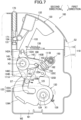
- the hook 120 When the seat back S2 is inclined further rearward from the state in FIG. 6 , the hook 120 is pushed in the first direction by the striker ST, and, as shown in FIG. 7 , the striker ST enters the first groove part 122A of the engaging groove 122. At this time, the opposed part 125 and its end portion 125A of the hook 120 pushes the first lock cam 140 upward, and rotates the first lock cam 140 in the second direction. Thus, the release lever 130 is caused to rotate in the first direction by the first lock cam 140.
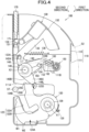
- the hook 120 When the seat back S2 is inclined further rearward from the state in FIG. 7 , the hook 120 is pushed in the first direction by the striker ST in the first groove part 122A, and, as shown in FIG. 8 , the first lock surface 125B of the hook 120 is located outside of the rotatable region of the second arm 143 of the first lock cam 140. In other words, in FIG. 8 , the first lock surface 125B is located to the right of the first rotation prevention surface 143B of the second arm 143.
- the hook 120 is restrained from rotating further in the first direction by the second lock surface 125C contacting the second rotation prevention surface 154 of the second lock cam 150.
- the first lock cam 140 When the hook 120 no longer restrains the first lock cam 140 from rotating in the first direction, as in FIG. 8 , the first lock cam 140 is caused to rotate in the first direction by the biasing force of the torsion spring 148, as shown in FIG. 2 .
- the first rotation prevention surface 143B contacts the first lock surface 125B of the hook 120 and prevents the hook 120 from rotating in the second direction.
- the hook 120 prevented from rotating in the first direction by the second lock cam 150, and prevented from rotating in the second direction by the first lock cam 140 to thereby lock in the first position.
- the position of the latch 100 in this state will be referred to as the "first lock position.”
- the seat back S2 When the latch 100 is in the first lock position as shown in FIG.2 the seat back S2 is locked in the raised position.
- the striker ST When the latch 100 is in the first lock position, the striker ST is fixed in a first fixed position relative to the latch 100.
- the release lever 130 To incline the seat back S2 frontward from the raised position in FIG. 2 , or to incline the seat back S2 rearward to the reclining position, the release lever 130 is pulled frontward to release the lock, as shown in FIG. 9 .
- the connecting arm 133 pushes the pin 142A of the first lock cam 140, and the fist lock cam 140 is caused to rotate in the second direction.
- the pin 143A engages with the notch 163 of the interlocking link 160 and pushes the interlocking link 160 upward. And then, the interlocking link 160 pulling up the pin 152 of the second lock cam 150 rotates the second lock cam 150 in the first direction.
- the position of the second lock cam 150 is determined by the guide protrusion 153 contacting the upper end of the guide hole 111B.
- the hook 120 is made rotatable in the first direction and in the second direction.
- the seat back S2 is rendered capable of being freely inclined frontward or rearward.
- a state of the latch 100 in which the release lever 130 is firmly pulled frontward and the hook 120 is rotatable without interfering with the first lock cam 140 and the second lock cam 150 will be referred to as "release position.”
- the striker ST pushes and causes the hook 120 to rotate in the first direction. Then, the striker ST moves inside the first groove part 122A of the engaging groove 122 toward the second groove part 122B and arrive at a position between the first groove part 122A and the second groove part 122B, as shown in FIG. 10 (a) . Afterwards, when the seat back S2 is inclined further rearward, the striker ST enters the second groove part 122B as shown in FIG. 10 (b) , and when the striker ST contacts an innermost end surface 111E of the receiving groove 111A, as shown in FIG. 10 (c) , the hook 120 is made unable to rotate further in the first direction.
- the release lever 130 is returned to the initial position by the biasing force of the spring 138 and the first lock cam 140 rotates in the first direction by the biasing force of the torsion spring 148, as shown in FIG. 11 .
- the first rotation prevention surface 143B of the main cam 140A contacts the contact surface 124A of the hook 120.
- the first rotation prevention surface 143B prevents the hook 120 from rotating in the second direction.
- the hook 120 is prevented from rotating in the first direction by the striker ST held between the hook 120 and the end surface 111E of the main frame 111, and prevented from rotating in the second direction by the first lock cam 140.
- the seat back S2 is locked in the reclining position.
- the position of the latch 100 in this state will be referred to as "second lock position.”
- the striker ST is fixed in a second fixed position relative to the latch 100.
- the second fixed position is a position deeper toward the bottom of the receiving groove 111A than to the first fixed position.
- the release lever 130 is operated to place the latch 100 in the release position in FIG. 10 (c) , and the seatback S2 is moved frontward.
- the release lever 130 is returned when the seat back S2 is in the raised position.
- the release lever 130 is pulled until the striker ST is disengaged from the hook 120, and the release lever 130 is returned after the striker ST is disengaged from the hook 120.
- the striker ST is located in the first groove part 122A when the hook 120 is in the first position, and the striker ST is located in the second groove part 122B when the hook 120 is in the second position.
- the first groove part 122A and the second groove part 122B are connected and forms a single engaging groove 122, and thus while the seat back S2 is moved from the raised position to the reclining position, the striker ST remains engaged in the engaging groove 122. Therefore, the striker ST can be smoothly locked in the two positions.
- the engaging groove 122 can be easily positioned to cross the direction in which the receiving groove 111A extends in both of the situations: when the hook 120 is in the first position and when the hook 120 is in the second position.
- the striker ST can be rotated by pressing the striker ST against the hook 120.
- the second lock cam 150 prevents the rotation of the hook 120 in the first direction and the first lock cam 140 prevents the rotation of the hook 120 in the second direction; therefore the seat back S2 can be firmly locked.
- the second lock cam 150 can be moved synchronously with the first lock cam 140.
- the latch 100 in the first embodiment can be applied even to a particular configuration in which the striker ST have only one bar-shaped part that engages with the hook 120.
- a latch 200 according to the second embodiment can also be used to lock the seat back S2 in the raised position and the reclining position, as in the latch 100 described in the first embodiment.
- the latch 200 is, for example, fixed to and used for the seat back S2 as shown in FIG. 1 .
- the latch 200 similar to the latch 100, can take the first lock position for locking the seat back S2 in the raised position (refer to FIG. 15 ), and the second lock position for locking the seat back S2 in the reclining position (refer to FIG. 20 ). It is understood that the first lock position and the second lock position are different only in the position of the striker ST relative to the latch 200, and the state of the latch 200 itself remains unchanged.
- the striker ST When the latch 200 is in the first lock position, the striker ST is fixed to a first fixing position as a position relative to the latch 200. When the latch 200 is in the second lock position, the striker ST is fixed to a second fixed position as another position relative to the latch 200.
- the second fixed position is a position deeper toward the bottom of a receiving groove 211A further inward than.
- the latch 200 integrated with the lever mainly comprises a frame 210, a hook 220, a release lever 230, a lock cam 240, a pressing arm 250, an interlocking link 260, a flag 270, a finger member 280 (prop finger), and a link 290.
- the striker ST includes a U-shaped bar having a first pin P1 and a second pin P2 disposed to the rear of the first pin P1.
- the front/rear (frontward/rearward) and up/down (upward/downward; upper/lower) are represented with reference to the seat S in FIG. 1 , as in the first embodiment.
- the frame 210 comprises a main frame 211 supporting the hook 220, the lock cam 240, the pressing arm 250 and the finger member 280, and a lever frame 215 supporting the release lever 230 and the flag 270.
- the lever frame 215 is fixed to the top of the main frame 211.
- the frame 210 is configured to include a cover not shown in the figures and forms a housing comprised of the main frame 211 and the lever frame 215 shown in the figures, and the cover, for stowing each component.
- the main frame 211 has a receiving groove 211A capable of receiving a striker ST.
- the receiving groove 211A extends in an approximately straight line. Specifically, the receiving groove 211A extends in a gentle curve along a segment of a circle the center of which coincides with the rotation axis of the seat back S2.
- the main frame 211 includes a support wall W11 that supports the hook 220 and other components, and a side wall W12 extending along the outer edge of the support wall W12 in a direction perpendicular to the support wall W12 such that the components are surrounded by the side wall W12.
- the side wall W12 may be integrally formed with the support wall W 11, or may be a member formed of a member other than the support wall W11.
- the side wall W12 may be formed as a part of the cover to be placed over the support wall W11 to house the components in combination with the support wall W11.
- the hook 220 is formed of a thick metal plate.
- the hook 220 may be covered partially or entirely with plastic, rubber or the like.
- the hook 220 is rotatably supported by the main frame 211.
- the hook 220 is rotatable about an axis X11 in a first direction, that is, a clockwise direction in FIG. 12 , and a second direction opposite to the first direction.
- the hook 220 comprises a first engaging groove 222A in which the striker ST is engageable, and a second engaging groove 222B which is located at a position different from the first engaging groove 222A and in which the striker ST is engageable.
- the second engaging groove 222B is closer, than the first engaging groove 222A, to the rotation axis X11, i.e. the center of rotation, of the hook 220.
- the first engaging groove 222A and the second engaging groove 222B extend in directions non-parallel to a direction away from the axis X11 as viewed with a line of sight aligned with the axis X11 (for convenience, with reference to a direction of a radius of a circle the center of which coincides with the axis X11, this direction will be referred to as "radial direction" in the present embodiment).
- the distance between the first engaging groove 222A and the second engaging groove 222B are similar to the distance between the first pin P1 and the second pin P1 of the striker ST.
- the hook 220 is rotatable between an engaging position in which the first engaging groove 222A and the second engaging groove 222B cross the receiving groove 211A and the striker ST is engageable with at least one of the first engaging grove 222A and the second engaging groove 222B (refer to FIG. 15 and FIG. 20 ), and a non-engaging position in which the first engaging groove 222A and the second engaging groove 222B are retreated from the receiving groove 211A such that the striker ST is movable inside of the receiving groove 211A (refer to FIG. 19 ).
- the state in FIG. 12 is a state in which the release lever 230 is not operated and the striker ST is not engaged with the hook 220, and the position of the latch 200 in this state will be referred to as "disengaged position.”
- the hook 220 comprises a body part 223A, a first protrusion 223B, a second protrusion 223C, and a third protrusion 223D.
- the body part 223A is a part elongated in the front-rear direction and has a bearing hole 221 in one end portion thereof.
- the body part 223A also has a hole 220J and a hole 220K in an upper part thereof.
- a hollow cylindrical shaft 229 is inserted in the bearing hole 221.
- the shaft 229 inserted in the bearing hole 221 is fixed to the main frame 211.
- the shaft 229 thus connects the hook 220 to the main frame 211 in a manner that permits the hook 220 to rotate.
- the shaft 229 is located on the extension line of the receiving groove 211A.
- the first protrusion 223B extends from an end portion of the body part 223A opposite to the end portion in which the bearing hole 221 is provided, in a direction non-parallel to the radial direction.
- the second protrusion 223C is provided between the bearing hole 221 and the first protrusion 223B, and extends in a direction non-parallel to the radial direction.
- the third protrusion 223D is provided between the bearing hole 221 and the second protrusion 223C, and extends in a direction non-parallel to the radial direction.
- An opening provided between the first protrusion 223B and the second protrusion 223C forms the first engaging groove 222A.
- the second protrusion 223C has an end portion 220T that protrudes farther than that of the first protrusion 223B.
- the first protrusion 223B has an inclined surface 220F inclined relative to the radial direction at a side thereof farther away from the axis X11.
- the inclined surface 220F is inclined upward with distance, relative to the radial direction, from the axis X11.
- the body part 223A has a back surface 220B at a side facing away from the first protrusion 223B, the second protrusion 223C, and the third protrusion 223D.
- the back surface 220B is a surface that contacts the lock cam 240 when the rotation of the hook 220 in the first direction is prevented by the lock cam 240.
- the hook 220 includes a sub-plate 225.
- the sub-plate 225 is located at one side, of the body part 223A (behind the body part 223A in FIG. 13 ), facing in a direction parallel to the axis X11 (hereafter, referred to as "axial direction" in the present embodiment). In other words, the sub-plate 225 is located at a position shifted from a position of the hook 220 in the axial direction.
- the sub-plate 225 has a hole 225A and a hole 225B.
- the sub-plate 225 is fixed to the body part 223 A by a pin 226 inserted into the hole 220J and the hole 225A and a pin 227 inserted in the hole 225B and the hole 220K.
- the sub-plate 225 has a to-be-pressed surface 225T provided at an upper part thereof and protruding farther than the back surface 220B in a direction perpendicular to the axial direction.
- the to-be-pressed surface 225T is formed as a gently curved surface.
- the latch 200 comprises a torsion spring 228 as a second spring that biases the hook 220 from the non-engaging position toward the engaging position.
- the hook 220 is biased in the second direction by the torsion spring 228.
- An arm of the torsion spring 228 is engaged with the hook 220, and the other arm is engaged with the main frame 211.
- the lock cam 240 is made by forming a metal plate.
- the lock cam 240 includes a bearing hole 241, a first connecting hole 242, and a second connecting hole 243, and a protrusion 244.
- the lock cam 240 approximately has a shape of a fan that spreads out downwards.
- a hollow cylindrical shaft 249 is inserted in the bearing hole 241.
- the shaft 249 is fixed to the main frame 211.
- the lock cam 240 is supported via the shaft 249 rotatably about an axis X12.
- the lock cam 240 is rotatable between a lock position in which the rotation of the hook 220 is prevented (refer to FIG. 15 and FIG. 20 ) and an unlocked position in which the rotation of the hook is not prevented (refer to FIG. 19 ).
- the lock cam 240 is biased in the first direction by a torsion spring 248A.
- One arm of the torsion spring 248A is engaged with the lock cam 240 and the other arm is engaged with the main frame 211.
- the protrusion 244 protrudes in one direction parallel to the axial direction (on a far side of the lock cam 240 FIG. 13 ).
- the lock cam 240 has a lock surface 245 at its lower side.
- the lock surface 245 has a gently curved surface that approximates to a segment of a circle having a center of which coincides with the axis X12.
- the lock cam 240 has a contact surface 246 which is provided at an end, of the lock surface 245, facing in the first direction, and of which a radius of curvature is smaller than that of the lock surface 245.
- the lock cam 240 When the hook 220 is in the engaging position (refer to FIG. 15 and FIG. 20 ), the lock cam 240 is in a normal state distanced from the hook 220. However, when the hook 220 rotates a predetermined amount from the engaging position toward the non-engaging position, the surface 220B of the hook 220 contacts the lock surface 245 of the lock cam 240, thereby preventing the hook 220 rotating from the engaging position to the non-engaging position.
- the pressing arm 250 is elongated in the up-down direction.
- the pressing arm 250 has a bearing hole 251 and a pressing surface 252.
- the bearing hole 251 is located in one end portion of the pressing arm 250 in the lengthwise direction of the pressing arm 250.
- the pressing surface 252 is located at the other end portion of the pressing arm 250 in the lengthwise direction.
- the pressing surface 252 forms a gently curved protruding surface.
- the pressing surface 252 is slightly inclined relative to a circumference of a circle of which a center coincides with the axis X12. Specifically, the further in the second direction along the circumferential direction of the circle of which the center coincide with the axis X12, the farther the distance between the pressing surface 252 and the axis X12 is.
- the shaft 249 is inserted in the bearing hole 241.
- the pressing arm 250 is supported by the main frame 111 rotatably via the shaft 249.
- the pressing arm 250 is supported by the main frame 111 rotatably about the same axis as the axis of rotation of the lock cam 240.
- the pressing arm 250 is rotatable relative to the lock cam 240.
- the latch 200 comprises a torsion spring 248B as a first spring that biases the pressing arm 250 in the first direction that is a direction of its rotation relative to the lock cam 240.
- One arm of the torsion spring 248B is engaged with the lock cam 240, and the other arm is engaged with the pressing arm 250.
- the torsion spring 248B biases the pressing arm 250 toward the hook 220. From this, the pressing arm 250 is pressed against the hook 220 when the hook 220 is in the engaging position (refer to FIG. 15 and FIG. 20 ).
- the pressing surface 252 is pressed against the to-be-pressed surface 225T of the sub-plate 225 by the pressing arm 250 being biased in the first direction by the torsion spring 248B.
- the pressing arm 250 is located above the protrusion 244, and contact the protrusion 244 to thereby prevent the lock cam 240 from rotating further in the first direction relative to the lock cam 240.
- the protrusion 244 and the pressing arm 250 rotates together.
- the lock cam 240 moves from the lock position to the unlock position, for example, when the latch 220 changes from the state in FIG. 15 to the state in FIG. 18 , the pressing arm 250 is pushed up by the protrusion 244 and rotates together with the lock cam 240, and is separated from the hook 220.
- the interlocking link 260 connects the lock cam 240 and the hook 220, which are thus rendered movable synchronously.
- the interlocking link 260 has an elongated shape and have a hole 261 at one end thereof and a long hole 262 at the other end thereof.
- the long hole 262 extends in the lengthwise direction of the interlocking link 260.
- a pin 269 is inserted in the hole 261.
- the pin 269 is fixed to the second connecting hole 243 of the lock cam 240.
- the long hole 262 engages with the pin 226.
- the interlocking link 260 is rotatable relative to the hook 220.
- the interlocking link 260 moves the hook 220 from the engaging position to the non-engaging position when the lock cam 240 moves from the lock position to the unlocked position.
- the finger member 280 is made by forming a metal plate, and includes a bearing part 285, a first finger 282 extending from the bearing part 285, and a second finger 283 extending from the bearing part 285.
- the bearing part 285 has a hole 281.
- a hollow cylindrical shaft 289 is inserted in the hole 281.
- the shaft 289 is fixed to the main frame 111.
- the finger member 280 is thus supported by the main frame 111 rotatably via the shaft 289.
- the first finger 282 extends long to a position in which it crosses the receiving groove 211A.
- the second finger 283 is shorter than the first finger 282.
- the second finger 282 has a receiving part 283A bent in the axial direction at its end.
- the latch 200 comprises a torsion spring 288 biasing the finger member 280.
- the torsion spring 288 biases the finger member 280 in the second direction.
- One arm of the torsion spring 288 is engaged with the finger member 280, and the other arm is engaged with the main frame 111.
- the finger member 280 contacts a stopper (not shown) or the side wall W12, and is restrained from rotating in the second direction from the position in FIG. 12 .
- the first finger 282 of the finger member 280 contacts the striker ST inserted in the receiving groove 211A.
- the finger member 280 functions to push the striker ST out of the receiving groove 211A by the biasing force of the torsion spring 288. In other words, the finger member 280 assists the striker ST in getting detached from the latch 200.
- the receiving part 283A of the second finger 283 contacts the end part 220T of the second protrusion 223C of the hook 220. The position of the hook 220 is determined accordingly in the disengaged position.
- the release lever 230 comprises a shaft 231, a holding part 232, a connecting arm 233, and a flag operating part 234.
- the shaft 231 extends in the axis direction.
- the lever frame 215 supports the shaft 231 in a manner that allows the shaft 231 to rotate.
- the release lever 230 is thus rotatably supported by the lever frame 215.
- the latch 200 of FIG. 15 is such a state that the striker ST is engaged with the hook 220 and the release lever 230 is not operated; the position of the lever 230 at this state will be referred to as "initial position.”
- the release lever 230 is stopped from rotating in the second direction from the initial position in FIG. 15 by a stopper not shown in the figures.
- a lock state refers to a state in which the striker ST is engaged with the hook 120 and the hook 220 is made unable to move to the non-engaging position (refer to FIG. 19 ), and an unlocked state refers to a state other than the lock state (the unlocked state includes a release position which will be described later).
- the holding part 232 extends upward from the shaft 231.
- the holding part 232 is exposed at the upper part of the seat back S2.
- the connecting arm 233 extends downward from the holding part 232.
- the connecting arm 233 has an engaging hole 233A at its end portion.
- An end portion of the link 290 is rotatably connected to the engaging hole 233A.
- the flag operating part 234 protrudes to the rear.
- the flag 270 is a member that shows to the outside that the latch 200 is in the unlocked state.
- the flag 270 does not protrude much from the upper surface of the lever frame 215 when the hook 220 is engaged with the striker ST and the latch 200 is thus in the lock state, as in FIG. 15 and FIG. 20 .
- the flag 270 may not protrude from the upper surface of the lever frame 215 when the latch 200 is in the lock state.
- the flag 270 has an engaging hole 271.
- the flag operating part 234 of the release lever 230 is inserted into the engaging hole 271. When the release lever 230 rotates from the initial positon in FIG. 15 to the front of the seat S, the flag operating part 234 pushes the flag 270 upward, and the flag 270 protrude from the upper surface of the lever frame 215 (refer to FIG. 12 and FIG. 19 ).
- the link 290 is a member formed by a wire. One end portion of the link 290 is rotatably connected to the release lever 230 as described above. The other end portion of the link 290 is rotatably connected to the first connecting hole 242 of the lock cam 240. Therefore, the latch 200 is configured such that the motion of the release lever 230 is transmitted to the lock cam 240 via the link 290 and the motion of the lock cam 240 is transmitted to the release lever 230 via the link 290.
- the latch 200 is attached to the seat back S2 by inserting bolts in at least two of the shaft 229, the shaft 249, and the shaft 289 and fixing the bolts to the frame of the seat back S2.
- the end portion 220T of the hook 220 contacts the receiving part 283A of the finger member 280, and the position of the hook 220 is decided.
- the lock cam 240 is biased by the torsion spring 248A in the first direction and the contact surface 246 contacts the back surface 220B of the hook 220, whereby its position is determined.
- the release lever 230 and the interlocking link 260 are in positions in accordance with the position of the lock cam 240.
- the flag 270 is pushed up by the flag operating part 134, and protrudes through the upper surface of the lever frame 215 to show the latch 200 is the unlocked state.
- the striker ST contacts the inclined surface 220F of the hook 220 and pushes aside the hook 220 upward, as shown in FIG. 14 .
- the striker ST also pushes and rotates the finger member 280 in the first direction.
- the lock cam 240 is caused to rotate in the second direction by the back surface 220B of the hook 220 pushing the contact surface 246 of the lock cam 240.
- the release lever 230 and the flag 270 moves in accordance with the movement of the lock cam 240.
- the striker ST When the seat back S2 is further inclined rearward from the state in FIG. 14 , the striker ST is detached from the first protrusion 223B and, as shown in Fig. 15 , the striker ST enters the first engaging groove 222A.
- the hook 220 rotates in the second direction by the biasing force of the torsion spring 228, and stops at a position in which the bottom of the first engaging groove 222A contacts the striker ST.
- the lock cam 240 rotates in the first direction by the biasing force of the torsion spring 248, and stops at a position in which the release lever 230 is in the initial position.
- the pressing arm 250 rotates in the first direction by the biasing force of the torsion spring 248B, and the pressing surface 252 contacts the to-be-pressed surface 225T.
- the hook 220 is locked so as to not rotate easily in the first direction by the to-be-pressed surface 225T contacting the pressing surface 252.
- the pressing arm 250 restrains the hook 220 from getting loosened.
- the latch 200 comes in the first lock position.
- the flag 270 is lowered and shows that the latch 200 is in the lock state.
- the hook 220 is separated a predetermined distance from the lock cam 240.
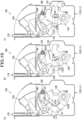
- FIG. 16 (a) to FIG. 16 (c) are figures describing a state in which the position of the striker ST relative of the latch 200 varies: FIG. 16 (b) shows a state when the striker ST is in a middle position, FIG. 16 (a) shows a state when the striker ST is in a position shifted downward, and FIG. 16 (c) shows a state when the striker ST is in a position shifted upward.
- the position of the hook 220 is determined by the bottom of the first engaging groove 222A contacting the striker ST.
- the pressing arm 250 autonomously closes the gap between the hook 220 and the pressing arm 250, and contacts the hook 220 according to the shift of the position of the striker ST. Therefore, the hook 220 can be restrained from shaking even if the position of the striker ST relative to the latch 200 varies due to a position error as would be introduced in installation of the striker ST and/or the latch 200.
- the pressing arm 250 and the hook 220 may be shaken due to the inertia, and the pressing arm 250 may become disengaged from the hook 220.
- the lock of the hook 220 by the pressing arm 250 is released, but the back surface 220B of the hook 220 contacts the lock surface 245 of the lock cam 240, thereby preventing the hook 220 rotating from the engaging position to the non-engaging position.
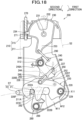
- the release lever 230 When the seat back S2 is moved from the first lock position, the release lever 230 is pulled frontward and caused to rotate as shown in FIG. 18 and FIG. 19 .
- the release lever 230 rotates in the first direction, first, as shown in FIG. 18 , the lock cam 240 rotates in the second direction and the protrusion 244 contacts the pressing arm 250, and pushes it up. The lock of the hook 220 by the pressing arm 250 is then released.
- the pin 226 is located at the lower end of the long hole 262 of the interlocking link 260, and the hook 220 is pulled upward by the interlocking link 260, as the interlocking link 260 moves upwards.
- the hook 220 is located in the non-engaging position, and the latch 200 is in the release position.
- the flag 270 is raised, showing that the latch 200 is in the unlocked state.
- the striker ST is freely movable inside the receiving groove 211A.
- the latch 200 comes in the disengaged position in FIG. 12 . If the seat back S2 with the latch 200 in the release position is inclined rearward to the reclining position, the striker ST is inserted into the bottom of the receiving groove 211A.
- the hook 220 is caused to rotate in the second direction by the torsion spring 228, and the second pin P2 contacts the bottom of the first engaging groove 222A.
- the first pin P1 enters the second engaging groove 222B.
- the lock cam 240 is caused to rotate in the first direction by the biasing force of the torsion spring 248A, and stops at a position in which the release lever 203 is in the initial position.
- the pressing arm 250 is caused to rotate in the first direction by the biasing force of the torsion spring 248B, and the pressing surface 252 contacts the to-be-pressed surface 225T.
- the hook 220 is locked so as not to rotate easily in the first direction by the to-be-pressed surface 225T contacting the pressing surface 252.
- the hook 220 is restrained from getting loosened the pressing arm 250.
- the latch 200 comes in the second lock position.
- the flag 270 is lowered, showing that the latch 200 is in the lock state.
- the hook 220 is separated a predetermined distance from the lock cam 240.
- the pin P2 is restrained from moving in the front-rear direction, and therefore the seat back S2 is securely locked.
- the pressing arm 250 restrains the hook 220 from shaking irrespective of variations in the position of the striker ST.
- the release lever 230 is pulled frontward and caused to rotate, and, the hook 220 is positioned in the non-engaging position as in FIG. 19 , and the latch 200 in the release position, the seat back S2 can be moved frontward and backward freely.
- a predetermined amount of rotation of the hook 220 from the engaging position toward the non-engaging position causes the lock cam 240 to contact the hook 220, and the lock is restrained from getting released.
- the hook 220 is in the engaging position, the pressing arm 250 is pressed against the hook 220 so that the hook 220 can be restrained from getting loosened. Therefore, shaking of the hook 220 shaking due to the vibration of the vehicle or the like can be restrained.
- the hook 220 can be restrained from shaking even if the position of the striker ST relative to the latch 200 varies due to a position error as would be introduced in installation of the striker ST and/or the latch 200 can also be restrained.
- the latch 200 comprises the torsion spring 248B, it can be ensured that the pressing arm 250 is pressed against the hook 220.
- the hook 220 can be moved from the engaging position to the non-engaging position by moving the lock cam 240 from the lock position to the unlocked position.
- the second embodiment may not have any first spring.
- Gravity can be used instead of the first spring, and, for example, a weight can be used to bias the pressing arm to the hook.
- the to-be-pressed surface 225T is provided on the sub-plate 225 in the second embodiment, but there may be no sub-plate 225.
- the hook 220 can be formed such that the to-be-pressed surface is provided in one member.
Landscapes
- Engineering & Computer Science (AREA)
- Aviation & Aerospace Engineering (AREA)
- Transportation (AREA)
- Mechanical Engineering (AREA)
- Seats For Vehicles (AREA)
Abstract
Description
- The present disclosure relate to a latch used in a seat back and the like.
- A latch capable of locking a seat back of a vehicle in two positions, i.e., can be raised higher to a raised position in which the luggage space is maximized, and can be inclined back from the raised position to a reclining position in which the occupant may be made more comfortable is conventionally known. The latch comprises a hook that engages with a striker fixed to the vehicle. The hook has two grooves for engaging with the striker when the seat back is in the two positions, the raised position and the reclining position.
- Patent Document 1:
JP2018-052395A - In the aforementioned technical scheme, when a state of the latch is shifted from a state in which the striker is not engaged with the hook to a state in which the striker is engaged with a first groove corresponding to the raised position, the hook temporary rotates in one direction. To cause the seat back to move from the raised position and get located in the reclining position, the hook is caused to rotate again in the same direction and the seat back is moved rearward, and the hook is caused to rotate reversely back to its engaged position.. On this occasion, the striker is engaged into the second groove after being disengaged from the first groove, and therefore the hook and the striker may not be smoothly engaged depending on the position of the seat back and the timing of the reverse rotation of the hook.
- It is an object of the present disclosure to provide a latch capable of smoothly locking the striker at two positions.
- A latch, as contrived for achieving the aforementioned object, locks the seat back at two positions: a raised position and a reclining position more inclined to the rear than the raised position. The latch comprises a frame having a receiving groove capable of receiving the striker, and a hook rotatably supported by the frame having an engaging groove to which the striker engages.
- The engaging groove is a single groove consisting of a first groove part extending from a part of the outer edge of the hook, and a second groove part bent from the first groove part and extending in a direction different from a direction in which the first groove part extends. The latch is configured such that, when the seat back is in the raised position, the hook is located in a first position and the striker is located in the first groove part, and when the seat back is in the reclining position, the hook is located in a second position that is a position of the hook rotated in a first direction from the first position and the striker is located in the second groove part.
- With this configuration, the striker is located in the first groove part when the hook is in the first position, and the striker is located in the second groove part when the hook is in the second position. Thus, the striker stays engaged in the engaging groove while the seat back is being moved from the raised position to the reclining position, so that the striker can be smoothly locked in the two positions. Since the second groove part extends in the direction different from the direction the first groove part extends, the engaging groove can be easily positioned to cross the receiving groove in both the situations: when the hook is in the first position and when the hook is in the second position.
- The second groove part may be closer, than the first groove part, to the rotational axis of the hook.
- With this configuration, the striker can be smoothly moved relative to the hook between the state in which the striker is engaged in the second groove part and the state in which the striker is engaged in the first groove part.
- The latch may further comprise a shaft that connects the hook to the frame in such a manner that the hook is rotatable. In this instance, the shaft is shifted relative to the receiving groove in one direction that is a direction perpendicular to a direction in which the receiving groove extends.
- With this configuration, the hook can be rotated by the striker by pressing the striker in the receiving groove against the hook.
- The latch may further comprise a lock member that prevents rotation of the hook located in the first position. The lock member incudes a first lock cam rotatably supported by the frame and preventing a rotation of the hook in the second direction opposite to the first direction, and a second lock cam preventing a rotation of the hook in the first direction.
- With this configuration, when the striker is engaged in the first groove part of the hook located in the first position, both the rotation of the hook in the first direction and the rotation of the hook in the second direction can be prevented.
- The first lock cam may also be configured to prevent the hook located in the second position from rotating in the second direction..
- The latch may further comprise an interlocking link that synchronizes the rotation of the first lock cam and rotation of the second lock cam, the interlocking link rotatable coaxially about a same axis as an axis of rotation of the first lock cam, and connected to the second lock cam.
- With this configuration, the second lock cam can be moved synchronously with the first lock cam.
- The hook is capable of moving to an open position that is a position of the hook rotated from the first position in the second direction. The first lock cam may include a contact portion that contacts the hook in the open positions and prevents the rotation of the hook in the first direction.
- In the conventional technical scheme, the hook in the lock state may be shaken due to the vibration of the vehicle, resulting in undesirable unlocking and/or production of noises.
- Thus, a latch that restrains shaking of the hook is provided in the present disclosure.
- A latch as contrived for restraining a play of the hook is a latch for locking the seat back in two positions: the raised position and the reclining position in which the seat back is inclined rearward further than in the raised position. The latch comprises: a frame having a receiving groove capable of receiving the striker; a hook having a first engaging groove in which the striker is engagable and a second engaging groove in which the striker is engageable, the second engaging groove being located at a position different from a position of the first engaging groove, which first and second groove crosses the receiving groove, the hook being capable of rotating between an engaging position in which the striker is capable of engaging in at least one of the grooves consisting of the first engaging groove and the second engaging groove, and a non-engaging position in which the hook is retreated from the receiving groove such that the striker is movable inside the receiving groove; a lock cam rotatably supported by the frame, the lock cam configured to contact the hook to prevent the hook from moving toward the non-engaging position when the hook has rotated a predetermined amount from the engaging position to the non-engaging position; and a pressing arm rotatable relative to the lock cam and configured to be pressed against the hook when the hook is in the engaging position.
- With this configuration, if the hook is rotated a predetermined amount toward the non-engaging position from the engaging position, contact of the lock cam with the hook can restrain the latch from unlocking. Since the pressing arm is pressed against the hook when the hook is in the engaging position, the loosening of the hook can be restrained. Thus the shaking of the hook such as due to the vibration of the vehicle can be restrained. The shaking of the hook can also be restrained even if the position of the striker relative to the latch varies due to a position error as would be introduced in installation of the striker and the latch.
- It is preferable for the latch to further comprise a first spring that biases the pressing arm toward the hook.
- By comprising the first spring, the pressing arm can be securely pressed against the hook.
- The latch may further comprise a second spring that biases the hook in a direction from the non-engaging position toward the engaging position.
- The lock cam is capable of rotating between the lock position in which the hook is prevented from rotating and an unlocked position in which the hook is not prevented from rotating, and the pressing arm can be configured such that when the lock cam moves from the lock position to the unlocked position, the pressing arm rotates together with the lock cam and separates from the hook.
- The latch may further comprise an interlocking link that connects the lock cam and the hook in a way that renders the lock cam and the hook synchronously movable, wherein the interlocking link causes the hook to move from the engaging position to the non-engaging position when the lock cam moves from the lock position to the unlocked position.
- With this configuration, the hook can be moved from the engaging position to the non-engaging position by moving the lock cam from the lock position to the unlocked position.
- The hook may comprise a pin, and the interlocking link may have a long hole in which the pin is engageable.
- The pressing arm may be supported by the frame in such a manner that the pressing arm is rotatable coaxially with the lock cam.
-
- [
FIG. 1 ] is a diagram showing a state of a latch attached to a vehicle seat. - [
FIG. 2 ] is a diagram showing a latch of a first embodiment in a first lock position. - [
FIG. 3 ] is an exploded perspective view of the latch of the first embodiment. - [
FIG. 4 ] is a diagram of the hook in an open position according to the first embodiment. - [
FIG. 5 ] is a diagram showing a state in which the hook has been pushed and moved from the open position by a striker according to the first embodiment. - [
FIG. 6 ] is a diagram showing a state in which the release lever has been returned from the state inFIG. 5 . - [
FIG. 7 ] is a diagram showing a state in which the hook has been further pushed and moved by the striker from the state inFIG. 6 . - [
FIG. 8 ] is a diagram showing a state in which the hook has been further pushed and moved by the striker from the state inFIG. 7 to a position just before the first lock position. - [
FIG. 9 ] is a diagram showing a state in which the release lever has been pushed down from the first lock position until the lock is released according to the first embodiment. - [
FIG. 10 ] includes diagrams (a) to (c) showing a process in which the hook is pushed by the striker located in a first groove part, and the striker moves to a second groove part. - [
FIG. 11 ] is a diagram showing a state in which the latch is in the second lock position. - [
FIG. 12 ] is a diagram showing a latch of a second embodiment in a disengaged position in which the striker is not engaged to a hook. - [
FIG. 13 ] is an exploded perspective view of the latch of the second embodiment. - [
FIG. 14 ] is a diagram showing a state where the hook has been pushed and moved by the striker from the state inFIG. 12 . - [
FIG. 15 ] is a diagram showing the latch in a first lock position according to the second embodiment. - [
FIG. 16 ] includes diagrams for describing a lock state in which the position of the striker relative to the latch varies up and down according to the second embodiment. - [
FIG. 17 ] is a diagram describing a state in which the hook is lifted due to the vibration of the vehicle. - [
FIG. 18 ] is a diagram showing a pressing arm separated by the operation of the release lever according to the second embodiment. - [
FIG. 19 ] is a diagram showing the latch located in the release position by the operation of the release lever according to the second embodiment. - [
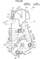
FIG. 20 ] is a diagram showing a latch in the second lock position according to the second embodiment. - Hereinafter, the first embodiment of a vehicle seat will be described with reference to the drawings.
- As shown in
FIG. 1 , alatch 100 integrally formed with a lever is used to lock a position of a vehicle seat S. The seat S is, for example, a rear seat of an automobile, and comprises a seat cushion S1, a seat back S2, and a headrest S3. A striker ST having a bar-shaped portion is fixed to a vehicle body of the vehicle. In the present embodiment, the front/rear (frontward/rearward) and up/down (upward/downward; upper/lower) are represented with reference to the seat S inFIG. 1 . In other words, inFIG. 1 , the right is the front and the left is the rear. - The
latch 100 is fixed to the seat back S2. Thelatch 100 includes ahook 120. Thelatch 100 locks the position of the seat back S2 by thehook 120 engaging with the striker ST. Specifically, thelatch 100 can lock the seat back S2 in two positions; a raised position shown by the solid line and a reclining position shown by the dotted line which reclining position is a position in which the seat back is inclined rearward further than in the raised position. When thelatch 100 is in an unlocked state, the seat back S2 may be inclined frontward, and thus the seat back S2 may also be folded on top of the seat cushion S1 as shown by the dotted line. - As shown in
FIG. 2 andFIG. 3 , thelatch 100 mainly includes aframe 110, ahook 120, arelease lever 130, afirst lock cam 140 and asecond lock cam 150 as a lock member, an interlockinglink 160, aflag 170, ashaft 129, and ashaft 149. - The
frame 110 includes amain frame 111 supporting thehook 120, thefirst lock cam 140, and thesecond lock cam 150, and alever frame 115 supporting therelease lever 130 and theflag 170. Thelever frame 115 is fixed to the top of themain frame 111. Though omitted in the figures, theframe 110 is configured to include a cover not shown in the figures and forms a housing comprised of themain frame 111 and thelever frame 115 shown in the figures, and the cover, for stowing each component. - The
main frame 111 has a receivinggroove 111A capable of receiving the striker ST. The receivinggroove 111A extends in an approximately straight line. Specifically, the receivinggroove 111A extends in a gentle curve along a segment of a circle the center of which coincides with the rotation axis of the seat back S2. Themain frame 111 includes a support wall W1 that supports thehook 120 and other components, and a side wall W2 extending along the outer edge of the support wall W1 in a direction perpendicular to the support wall W1 such that the components are surrounded by the side wall W2. The side wall W2 may be integrally formed with the support wall W1, or may be a member formed of a member other than the support wall W1. For example, the side wall W2 may be formed as a part of the cover to be placed over the support wall W1 to house the components in combination with the support wall W1. - The
hook 120 is made of a thick metal plate by press forming. Thehook 120 may be covered partially or entirely with plastic, rubber or the like. Thehook 120 is rotatably supported by themain frame 111. Thehook 120 is rotatable about an axis X1 in a first direction, that is, a clockwise direction inFIG. 2 , and a second direction opposite to the first direction. Specifically, thehook 120 can be moved to a first position shown inFIG. 2 , rotated in the first direction from the first position to a second position (refer toFIG. 11 ), and rotated in a second direction from the first position to an open position (refer toFIG. 4 ). - The
hook 120 has an engaginggroove 122 in which the striker ST is engageable. The engaginggroove 122 is a single groove consisting of afirst groove part 122A extending from a part of an outer edge of thehook 120 and asecond groove part 122B that is bent from thefirst groove part 122A and extends in a direction different from a direction in which thefirst groove part 122A extends. Thesecond groove part 122B is closer, than thefirst groove part 122A, to the axis X1, i.e. the center of rotation, of thehook 120. Thesecond groove part 122B extends in a direction away from the axis X1 as viewed with a line of sight aligned with the axis X1 (for convenience, with reference to a direction of a radius of a circle the center of which coincides with the axis X1, this direction will be referred to as "radial direction" in the present embodiment). Specifically, thesecond groove part 122B extends in a direction slightly oblique deviating from the radial direction. Thefirst groove part 122A extends in a direction approximately perpendicular to thesecond groove part 122B. Thesecond groove part 122B is oblique relative to the radial direction. - The
hook 120 includes abearing part 123, ahook part 124, and anopposed part 125. - The
bearing part 123 has abearing hole 121. Theshaft 129 is inserted in thebearing hole 121. Theshaft 129 when inserted into thebearing hole 121, is fixed to themain frame 111. Theshaft 129 thus connects thehook 120 to themain frame 111 in a manner that permits thehook 120 to rotate. Theshaft 129 is located in a position shifted relative to the receivinggroove 111A to one side in a direction perpendicular to the direction in which the receivinggroove 111A extends (an upward or downward direction inFIG. 2 ). In the present embodiment, theshaft 129 is located in a position shifted in the downward direction relative to the receivinggroove 111A. - The
hook part 124 extends from thebearing part 123. Theopposed part 125 is a part opposed to thehook part 124 across the engaginggroove 122. Thehook part 124 includes acontact surface 124A formed as a flat surface at an outer surface facing away from the engaginggroove 122. Thecontact surface 124A determines the position of thehook 120 when thehook 120 is in the open position (refer toFIG. 4 ), and is a part that thefirst lock cam 140 contacts to stop thehook 120 from rotating in the second direction when the hook is in the second position (refer toFIG. 11 ). - The
opposed part 125 includes anend portion 125A, afirst lock surface 125B, asecond lock surface 125C, and alock protrusion 125D. - The
end portion 125A protrudes farther than anend portion 124B of thehook part 124. - The
first lock surface 125B is formed in an approximately flat shape. Thefirst lock surface 125B is disposed adjacently to a side of theend portion 125A facing in the second direction. Thefirst lock surface 125B is a surface that thefirst lock cam 140 contacts to prevent thehook 120 from rotating in the second direction when thehook 120 is located in the first position shown inFIG. 2 . - The
second lock surface 125C is formed in an approximately flat shape. Thesecond lock surface 125C is disposed adjacently to a side of theend portion 125A facing in the first direction. Thesecond lock surface 125C is a surface that thesecond lock cam 150 contacts to prevent thehook 120 from rotating in the first direction when thehook 120 is located in the first position. - The
lock protrusion 125D protrudes toward one side (the front side of the drawing sheer ofFIGS. 2 and3 ) in a direction parallel to the axis X1 (hereafter, will be referred to simply as an "axial direction" in the present embodiment). Thelock protrusion 125D may be provided by press fitting a pin into theopposed part 125, or may be provided by half blanking a part of the opposingpart 125. - The
hook 120 is biased in the first direction by atorsion spring 128. One arm of thetorsion spring 128 is engaged with thehook 120 and the other arm is engaged with themain frame 111. - The
latch 100 is such that, when the seat back S2 is in the raised position, thehook 120 is located in the first position (the position inFIG. 2 ) and the striker ST is located in thefirst groove part 122A. Thelatch 100 is such that, when the seat back S2 is in the reclining position, thehook 120 is located in a second position (the position inFIG. 11 ) that is a position thehook 200 assumes when it is rotated in the first direction from the first position and the striker ST is located in thesecond groove part 122B. - The lock member (the
first lock cam 140 and the second lock cam 150) prevents the rotation of thehook 120 located in the first position. - The
first lock cam 140 includes amain cam 140A and a block outcam 140B. Thefirst lock cam 140 is biased in the first direction by atorsion spring 148. One arm of thetorsion spring 148 is engaged with themain cam 140A and the other arm is engaged with themain frame 111. - The
main cam 140A is made of a metal plate by press forming. Themain cam 140A includes a bearing hole 141, afirst arm 142, and asecond arm 143. Theshaft 149 is inserted in the bearing hole 141. Theshaft 149 is fixed to themain frame 111. Themain cam 140A is supported by themain frame 111, rotatably about an axis X2, via theshaft 149. - A
pin 142A protruding in the axial direction is fixed to thefirst arm 142. - A
pin 143A protruding in the axial direction is fixed to thesecond arm 143A. Thesecond arm 143 has at its end a firstrotation prevention surface 143B forming a nearly flat convex surface. The firstrotation prevention surface 143B contacts thefirst lock surface 125B of thehook 120 from rotating in the second direction, thereby preventing thehook 120 from rotating in the second direction. Thesecond arm 143 includes, at its lower side inFIG. 3 , arecess 143C that is engageable with theend portion 124B of thehook 120. When thehook 120 is in the first position, therecess 143C can engage with theend portion 124B of thehook 120. - The block out
cam 140B includes abearing hole 146A, afirst arm 146B, and asecond arm 146C. Theshaft 149 is inserted in thebearing hole 146A. The block outcam 140B is supported by themain frame 111, rotatably about the axis X2, via theshaft 149. A fitting hole 146H is formed in thefirst arm 146B. Thepin 143A is fitted in the fitting hole 146H. This enables themain cam 140A and the block outcam 140B to rotate about the axis X2 together. Thesecond arm 146C extends downwards. Thesecond arm 146C includes acontact part 146L at its end. Thecontact part 146L contacts theprotrusion 125D of thehook 120 in the open position and prevents the rotation of thehook 120 in the first direction. - The
second lock cam 150 is made of a metal plate by press forming. Thesecond lock cam 150 includes abearing hole 151, apin 152, aguide protrusion 153, and a secondrotation prevention surface 154. The secondrotation prevention surface 154 contacts thesecond lock surface 125C of thehook 120 in the first position, thereby preventing thehook 120 from rotating in the first direction. Ashaft 159 is inserted in thebearing hole 151. Theshaft 159 is fixed to themain frame 111. Thesecond lock cam 150 is thus supported by themain frame 111, rotatably about an axis X3, via theshaft 159. - The
pin 152 protrudes in one direction parallel to the axial direction. - The
guide protrusion 153 protrudes in the other direction parallel to the axial direction. Here, themain frame 111 includes aguide hole 111B extending along a segment of a circle the center of which coincides with the axis X3. Theguide protrusion 153 is inserted in theguide hole 111B. This enables thesecond lock cam 150 to rotate in the range that thelock guide protrusion 153 to move from one end of theguide hole 111B to the other end of theguide hole 111B. - The second
rotation prevention surface 154 is located at the end of thesecond lock cam 150. The secondrotation prevention surface 154 is a nearly flat convex surface. - The
shaft 159 has an engaginggroove 159A at one end thereof. A center-side end of aspiral spring 158 is engaged in the engaginggroove 159A. The other end of thespiral spring 158 is engaged with a side surface of thesecond lock cam 150. Thesecond lock cam 150 is biased in the second direction by thespiral spring 158. - The interlocking
link 160 is a member that interlocks the rotational motion of thefirst lock cam 140 with the rotational motion of thesecond lock cam 150. The interlockinglink 160 extends in the left-right direction ofFIG. 2 , and includes abearing hole 161, anelongated hole 162, and anotch 163. Theshaft 149 is inserted in thebearing hole 161. This enables the interlockinglink 160 to rotate about the same axis as an axis of rotation of thefirst lock cam 140. The interlockinglink 160 is connected to thesecond lock cam 150 by thepin 152 of thesecond lock cam 150 engaging with theelongated hole 162. Thenotch 163 can be engaged with thepin 143A when the interlockinglink 160 rotates in the first direction relative to thefirst lock cam 140. Thefirst lock cam 140 and theinterlocking link 160 rotate together coaxially about the axis X2 when thenotch 163 and thepin 143A are engaged. - The
release lever 130 includes ashaft 131, a holdingpart 132, a connectingarm 133, and aflag operating part 134. - The
shaft 131 extends in the axial direction. Thelever frame 115 supports theshaft 131 in a manner that permits theshaft 131 to rotate. Therelease lever 130 is thus rotatably supported by thelever frame 115. The position of therelease lever 130 inFIG. 2 is a position in a state that thelatch 100 is in a lock state and is not operated, and the position in this state will be referred to as "initial position." - The holding
part 132 extends upward from theshaft 131. The holdingpart 132 is exposed at the upper part of the seat back S2. The connectingarm 133 extends downward from the holdingpart 132. - The connecting
arm 133 has an engaginggroove 133A at its end. The engaginggroove 133A engages with thepin 142A of thefirst lock cam 140. Therefore, the rotational motion of thelever 130 is transmitted to the lock cam 141, and moment of thelock cam 140 is transmitted to therelease lever 130. A lower end portion of the connectingarm 133 is pulled frontward by aspring 138. Therelease lever 130 is thus biased in the second direction by thespring 138. - The
flag operating part 134 extends from theshaft 131 in a direction different from a direction in which the holdingpart 132 extends. In the present embodiment, theflag operating part 134 protrudes rearward from theshaft 131. - The
flag 170 is a member that shows to the outside that thelatch 100 is in the unlocked state. In the present embodiment, the lock state refers to a state that the striker ST is engaged with thehook 120 and thehook 120 cannot move, and the unlocked state refers to a state other than the lock state (including a state in which the latch is in a release position as described below). Theflag 170 does not protrude from the top surface of thelever frame 115 as shown inFIG. 2 , when thehook 120 engages with the striker ST and is in the lock state. Theflag 170 may slightly protrude from the top surface of thelever frame 115 when thelatch 100 is in the lock state. Theflag 170 has anengaging hole 171. Theflag operating part 134 of therelease lever 130 is inserted in the engaginghole 171. When therelease lever 130 rotates from the initial position inFIG.2 to the front of the seat S, theflag operating part 134 pushes theflag 170 upward, and thus theflag 170 protrudes from the upper surface of the lever frame 115 (refer toFIG. 4 and other drawing figures). - Operation of the
latch 100 configured as described above will be described. - As shown in
FIG. 4 , when therelease lever 130 is operated by being pulled toward the front and the striker ST is disengaged from thehook 120, putting thehook 120 in the open position, thecontact part 146L at the end of the block outcam 140B contacts thelock protrusion 125D of thehook 120. The block outcam 140B is biased in the first direction by thespring 138 and thetorsion spring 148, and therefore, even if thehook 120 is induced to rotate in the first direction to close, the block outcam 140B prevents the rotation of thehook 120 in the first direction. Rather, the block outcam 140B biases thehook 120 to cause it to rotate in the second direction, and thecontact surface 124A of thehook 120 contacts the side wall W2 of themain frame 111 to thereby determine the position of thehook 120. When thehook 120 is in the open position, therelease lever 130 is pulled toward the front, whereby theflag operating part 134 pushes theflag 170 upward. This makes it known to the user that the lock is released. - When the seat back S2 is inclined from the open position rearward and the striker ST contacts the
hook 120, the striker ST pushes and rotates thehook 120 in the first direction. Then, as shown inFIG. 5 , thelock protrusion 125D pushes aside the block outcam 140B and crosses over the end of thecontact part 146L. Thus, restraint laid on thehook 120 in rotating in the first direction by the block outcam 140B is lifted. - If the
release lever 130 is not operated in the state ofFIG. 5 , therelease lever 130 is returned to the initial position by thespring 138, as shown inFIG. 6 . - The
first lock cam 140 is rotated in the first direction from the state inFIG. 5 by the biasing force of thetorsion spring 148. The rotation of thefirst lock cam 140 in the first direction is stopped by thesecond arm 143 of themain cam 140A contacting thehook 120, and the position of thefirst lock cam 140 is determined. - The
second lock cam 150 is rotated in the second direction by the biasing force of thespiral spring 158. At this time, the second lock cam is stopped from further rotating in the second direction by theguide protrusion 153 contacting the lower end of theguide hole 111B, so that the position of thesecond lock cam 150 is determined. The position of the interlockinglink 160 is determined following the motion of thesecond lock cam 150. - When the seat back S2 is inclined further rearward from the state in
FIG. 6 , thehook 120 is pushed in the first direction by the striker ST, and, as shown inFIG. 7 , the striker ST enters thefirst groove part 122A of the engaginggroove 122. At this time, theopposed part 125 and itsend portion 125A of thehook 120 pushes thefirst lock cam 140 upward, and rotates thefirst lock cam 140 in the second direction. Thus, therelease lever 130 is caused to rotate in the first direction by thefirst lock cam 140. - When the seat back S2 is inclined further rearward from the state in
FIG. 7 , thehook 120 is pushed in the first direction by the striker ST in thefirst groove part 122A, and, as shown inFIG. 8 , thefirst lock surface 125B of thehook 120 is located outside of the rotatable region of thesecond arm 143 of thefirst lock cam 140. In other words, inFIG. 8 , thefirst lock surface 125B is located to the right of the firstrotation prevention surface 143B of thesecond arm 143. Thehook 120 is restrained from rotating further in the first direction by thesecond lock surface 125C contacting the secondrotation prevention surface 154 of thesecond lock cam 150. - When the
hook 120 no longer restrains thefirst lock cam 140 from rotating in the first direction, as inFIG. 8 , thefirst lock cam 140 is caused to rotate in the first direction by the biasing force of thetorsion spring 148, as shown inFIG. 2 . The firstrotation prevention surface 143B contacts thefirst lock surface 125B of thehook 120 and prevents thehook 120 from rotating in the second direction. In other words, thehook 120 prevented from rotating in the first direction by thesecond lock cam 150, and prevented from rotating in the second direction by thefirst lock cam 140 to thereby lock in the first position. The position of thelatch 100 in this state will be referred to as the "first lock position." - When the
latch 100 is in the first lock position as shown inFIG.2 the seat back S2 is locked in the raised position. When thelatch 100 is in the first lock position, the striker ST is fixed in a first fixed position relative to thelatch 100. To incline the seat back S2 frontward from the raised position inFIG. 2 , or to incline the seat back S2 rearward to the reclining position, therelease lever 130 is pulled frontward to release the lock, as shown inFIG. 9 . When therelease lever 130 is pulled frontward, the connectingarm 133 pushes thepin 142A of thefirst lock cam 140, and thefist lock cam 140 is caused to rotate in the second direction. When thefirst lock cam 140 rotates in the second direction, thepin 143A engages with thenotch 163 of the interlockinglink 160 and pushes the interlockinglink 160 upward. And then, the interlockinglink 160 pulling up thepin 152 of thesecond lock cam 150 rotates thesecond lock cam 150 in the first direction. The position of thesecond lock cam 150 is determined by theguide protrusion 153 contacting the upper end of theguide hole 111B. As shown inFIG. 9 , when thefirst lock cam 140 and thesecond lock cam 150 are located outside of the range of rotation of thehook 120 by the operation of therelease lever 130, thehook 120 is made rotatable in the first direction and in the second direction. In other words, the seat back S2 is rendered capable of being freely inclined frontward or rearward. A state of thelatch 100 in which therelease lever 130 is firmly pulled frontward and thehook 120 is rotatable without interfering with thefirst lock cam 140 and thesecond lock cam 150 will be referred to as "release position." - When the seat back S2 with the
latch 100 located in the release position is inclined to the rear, the striker ST pushes and causes thehook 120 to rotate in the first direction. Then, the striker ST moves inside thefirst groove part 122A of the engaginggroove 122 toward thesecond groove part 122B and arrive at a position between thefirst groove part 122A and thesecond groove part 122B, as shown inFIG. 10 (a) . Afterwards, when the seat back S2 is inclined further rearward, the striker ST enters thesecond groove part 122B as shown inFIG. 10 (b) , and when the striker ST contacts aninnermost end surface 111E of the receivinggroove 111A, as shown inFIG. 10 (c) , thehook 120 is made unable to rotate further in the first direction. - In this state, when the operation of the
release lever 130 is ceased and therelease lever 130 is set free, therelease lever 130 is returned to the initial position by the biasing force of thespring 138 and thefirst lock cam 140 rotates in the first direction by the biasing force of thetorsion spring 148, as shown inFIG. 11 . Accordingly, the firstrotation prevention surface 143B of themain cam 140A contacts thecontact surface 124A of thehook 120. Thereby, the firstrotation prevention surface 143B prevents thehook 120 from rotating in the second direction. Thehook 120 is prevented from rotating in the first direction by the striker ST held between thehook 120 and theend surface 111E of themain frame 111, and prevented from rotating in the second direction by thefirst lock cam 140. Thus, the seat back S2 is locked in the reclining position. The position of thelatch 100 in this state will be referred to as "second lock position." When thelatch 100 is in the second lock position, the striker ST is fixed in a second fixed position relative to thelatch 100. The second fixed position is a position deeper toward the bottom of the receivinggroove 111A than to the first fixed position. - To move the seat back S2 from the state in which the
latch 100 is in the second lock position and the seat back S2 is in the reclining position, therelease lever 130 is operated to place thelatch 100 in the release position inFIG. 10 (c) , and the seatback S2 is moved frontward. To lock the seat back S2 in the raised position therelease lever 130 is returned when the seat back S2 is in the raised position. To fold the seat back S2 on top of the seat cushion S1, therelease lever 130 is pulled until the striker ST is disengaged from thehook 120, and therelease lever 130 is returned after the striker ST is disengaged from thehook 120. - According to the above, the following advantageous effects can be achieved in the first embodiment. The striker ST is located in the
first groove part 122A when thehook 120 is in the first position, and the striker ST is located in thesecond groove part 122B when thehook 120 is in the second position. Thefirst groove part 122A and thesecond groove part 122B are connected and forms a singleengaging groove 122, and thus while the seat back S2 is moved from the raised position to the reclining position, the striker ST remains engaged in the engaginggroove 122. Therefore, the striker ST can be smoothly locked in the two positions. - Since the
second groove part 122B extends in a direction different from a direction in which thefirst groove part 122A extends, the engaginggroove 122 can be easily positioned to cross the direction in which the receivinggroove 111A extends in both of the situations: when thehook 120 is in the first position and when thehook 120 is in the second position. - Since the
second groove part 122B is closer, than thefirst groove part 122A, to the rotation axis X1 of thehook 120, the striker ST when moving from thefirst groove part 122A to thesecond groove part 122B gradually comes closer to the rotation axis X1. Therefore, the striker ST can be caused to move smoothly, between a state in which it is engaged with thesecond groove 122B and a state in which it is engaged with thefirst groove 122A, relative to thehook 120. - Since the
shaft 129 supporting thehook 120 is shifted relative to the receivinggroove 111A in a direction perpendicular to the direction in which the receivinggroove 111A extends, the striker ST can be rotated by pressing the striker ST against thehook 120. - When the
latch 100 is in the first lock position, thesecond lock cam 150 prevents the rotation of thehook 120 in the first direction and thefirst lock cam 140 prevents the rotation of thehook 120 in the second direction; therefore the seat back S2 can be firmly locked. - Since the interlocking
link 160 connects thefirst lock cam 140 and thesecond lock cam 150, thesecond lock cam 150 can be moved synchronously with thefirst lock cam 140. - The
latch 100 in the first embodiment can be applied even to a particular configuration in which the striker ST have only one bar-shaped part that engages with thehook 120. - Next, a second embodiment of a latch will be described with reference to
FIG. 12 to FIG. 20 . Descriptions of configurations substantially the same as those of the first embodiment will be omitted as appropriate. - A
latch 200 according to the second embodiment can also be used to lock the seat back S2 in the raised position and the reclining position, as in thelatch 100 described in the first embodiment. Though not shown in the figures, thelatch 200 is, for example, fixed to and used for the seat back S2 as shown inFIG. 1 . Thelatch 200, similar to thelatch 100, can take the first lock position for locking the seat back S2 in the raised position (refer toFIG. 15 ), and the second lock position for locking the seat back S2 in the reclining position (refer toFIG. 20 ). It is understood that the first lock position and the second lock position are different only in the position of the striker ST relative to thelatch 200, and the state of thelatch 200 itself remains unchanged. When thelatch 200 is in the first lock position, the striker ST is fixed to a first fixing position as a position relative to thelatch 200. When thelatch 200 is in the second lock position, the striker ST is fixed to a second fixed position as another position relative to thelatch 200. The second fixed position is a position deeper toward the bottom of a receivinggroove 211A further inward than. - As shown in
FIG. 12 andFIG. 13 , thelatch 200 integrated with the lever mainly comprises aframe 210, ahook 220, arelease lever 230, alock cam 240, apressing arm 250, an interlockinglink 260, aflag 270, a finger member 280 (prop finger), and alink 290. The striker ST includes a U-shaped bar having a first pin P1 and a second pin P2 disposed to the rear of the first pin P1. In the present embodiment, the front/rear (frontward/rearward) and up/down (upward/downward; upper/lower) are represented with reference to the seat S inFIG. 1 , as in the first embodiment. - The
frame 210 comprises amain frame 211 supporting thehook 220, thelock cam 240, thepressing arm 250 and thefinger member 280, and alever frame 215 supporting therelease lever 230 and theflag 270. Thelever frame 215 is fixed to the top of themain frame 211. Though omitted in the figures, theframe 210 is configured to include a cover not shown in the figures and forms a housing comprised of themain frame 211 and thelever frame 215 shown in the figures, and the cover, for stowing each component. - The
main frame 211 has a receivinggroove 211A capable of receiving a striker ST. The receivinggroove 211A extends in an approximately straight line. Specifically, the receivinggroove 211A extends in a gentle curve along a segment of a circle the center of which coincides with the rotation axis of the seat back S2. Themain frame 211 includes a support wall W11 that supports thehook 220 and other components, and a side wall W12 extending along the outer edge of the support wall W12 in a direction perpendicular to the support wall W12 such that the components are surrounded by the side wall W12. The side wall W12 may be integrally formed with the support wall W 11, or may be a member formed of a member other than the support wall W11. For example, the side wall W12 may be formed as a part of the cover to be placed over the support wall W11 to house the components in combination with the support wall W11. - The
hook 220 is formed of a thick metal plate. Thehook 220 may be covered partially or entirely with plastic, rubber or the like. Thehook 220 is rotatably supported by themain frame 211. Thehook 220 is rotatable about an axis X11 in a first direction, that is, a clockwise direction inFIG. 12 , and a second direction opposite to the first direction. - The
hook 220 comprises a firstengaging groove 222A in which the striker ST is engageable, and a secondengaging groove 222B which is located at a position different from the firstengaging groove 222A and in which the striker ST is engageable. The secondengaging groove 222B is closer, than the firstengaging groove 222A, to the rotation axis X11, i.e. the center of rotation, of thehook 220. The firstengaging groove 222A and the secondengaging groove 222B extend in directions non-parallel to a direction away from the axis X11 as viewed with a line of sight aligned with the axis X11 (for convenience, with reference to a direction of a radius of a circle the center of which coincides with the axis X11, this direction will be referred to as "radial direction" in the present embodiment). The distance between the firstengaging groove 222A and the secondengaging groove 222B are similar to the distance between the first pin P1 and the second pin P1 of the striker ST. Thehook 220 is rotatable between an engaging position in which the firstengaging groove 222A and the secondengaging groove 222B cross the receivinggroove 211A and the striker ST is engageable with at least one of the first engaginggrove 222A and the secondengaging groove 222B (refer toFIG. 15 andFIG. 20 ), and a non-engaging position in which the firstengaging groove 222A and the secondengaging groove 222B are retreated from the receivinggroove 211A such that the striker ST is movable inside of the receivinggroove 211A (refer toFIG. 19 ). The state inFIG. 12 is a state in which therelease lever 230 is not operated and the striker ST is not engaged with thehook 220, and the position of thelatch 200 in this state will be referred to as "disengaged position." - The
hook 220 comprises abody part 223A, afirst protrusion 223B, asecond protrusion 223C, and athird protrusion 223D. Thebody part 223A is a part elongated in the front-rear direction and has abearing hole 221 in one end portion thereof. Thebody part 223A also has ahole 220J and ahole 220K in an upper part thereof. A hollowcylindrical shaft 229 is inserted in thebearing hole 221. Theshaft 229 inserted in thebearing hole 221 is fixed to themain frame 211. Theshaft 229 thus connects thehook 220 to themain frame 211 in a manner that permits thehook 220 to rotate. Theshaft 229 is located on the extension line of the receivinggroove 211A. - The
first protrusion 223B extends from an end portion of thebody part 223A opposite to the end portion in which thebearing hole 221 is provided, in a direction non-parallel to the radial direction. Thesecond protrusion 223C is provided between the bearinghole 221 and thefirst protrusion 223B, and extends in a direction non-parallel to the radial direction. Thethird protrusion 223D is provided between the bearinghole 221 and thesecond protrusion 223C, and extends in a direction non-parallel to the radial direction. An opening provided between thefirst protrusion 223B and thesecond protrusion 223C forms the firstengaging groove 222A. An opening between thesecond protrusion 223C and thethird protrusion 223D forms the secondengaging groove 222B. Thesecond protrusion 223C has anend portion 220T that protrudes farther than that of thefirst protrusion 223B. Thefirst protrusion 223B has aninclined surface 220F inclined relative to the radial direction at a side thereof farther away from the axis X11. Theinclined surface 220F is inclined upward with distance, relative to the radial direction, from the axis X11. - The
body part 223A has aback surface 220B at a side facing away from thefirst protrusion 223B, thesecond protrusion 223C, and thethird protrusion 223D. Theback surface 220B is a surface that contacts thelock cam 240 when the rotation of thehook 220 in the first direction is prevented by thelock cam 240. - The
hook 220 includes a sub-plate 225. The sub-plate 225 is located at one side, of thebody part 223A (behind thebody part 223A inFIG. 13 ), facing in a direction parallel to the axis X11 (hereafter, referred to as "axial direction" in the present embodiment). In other words, the sub-plate 225 is located at a position shifted from a position of thehook 220 in the axial direction. The sub-plate 225 has ahole 225A and ahole 225B. The sub-plate 225 is fixed to thebody part 223 A by apin 226 inserted into thehole 220J and thehole 225A and apin 227 inserted in thehole 225B and thehole 220K. - The sub-plate 225 has a to-
be-pressed surface 225T provided at an upper part thereof and protruding farther than theback surface 220B in a direction perpendicular to the axial direction. The to-be-pressed surface 225T is formed as a gently curved surface. - The
latch 200 comprises atorsion spring 228 as a second spring that biases thehook 220 from the non-engaging position toward the engaging position. In other words, thehook 220 is biased in the second direction by thetorsion spring 228. An arm of thetorsion spring 228 is engaged with thehook 220, and the other arm is engaged with themain frame 211. - The
lock cam 240 is made by forming a metal plate. Thelock cam 240 includes abearing hole 241, a first connectinghole 242, and a second connectinghole 243, and aprotrusion 244. Thelock cam 240 approximately has a shape of a fan that spreads out downwards. - A hollow
cylindrical shaft 249 is inserted in thebearing hole 241. Theshaft 249 is fixed to themain frame 211. Thelock cam 240 is supported via theshaft 249 rotatably about an axis X12. Thelock cam 240 is rotatable between a lock position in which the rotation of thehook 220 is prevented (refer toFIG. 15 andFIG. 20 ) and an unlocked position in which the rotation of the hook is not prevented (refer toFIG. 19 ). Thelock cam 240 is biased in the first direction by atorsion spring 248A. One arm of thetorsion spring 248A is engaged with thelock cam 240 and the other arm is engaged with themain frame 211. Theprotrusion 244 protrudes in one direction parallel to the axial direction (on a far side of thelock cam 240FIG. 13 ). - The
lock cam 240 has alock surface 245 at its lower side. Thelock surface 245 has a gently curved surface that approximates to a segment of a circle having a center of which coincides with the axis X12. Thelock cam 240 has acontact surface 246 which is provided at an end, of thelock surface 245, facing in the first direction, and of which a radius of curvature is smaller than that of thelock surface 245. - When the
hook 220 is in the engaging position (refer toFIG. 15 andFIG. 20 ), thelock cam 240 is in a normal state distanced from thehook 220. However, when thehook 220 rotates a predetermined amount from the engaging position toward the non-engaging position, thesurface 220B of thehook 220 contacts thelock surface 245 of thelock cam 240, thereby preventing thehook 220 rotating from the engaging position to the non-engaging position. - The
pressing arm 250 is elongated in the up-down direction. Thepressing arm 250 has abearing hole 251 and apressing surface 252. Thebearing hole 251 is located in one end portion of thepressing arm 250 in the lengthwise direction of thepressing arm 250. Thepressing surface 252 is located at the other end portion of thepressing arm 250 in the lengthwise direction. Thepressing surface 252 forms a gently curved protruding surface. Thepressing surface 252 is slightly inclined relative to a circumference of a circle of which a center coincides with the axis X12. Specifically, the further in the second direction along the circumferential direction of the circle of which the center coincide with the axis X12, the farther the distance between thepressing surface 252 and the axis X12 is. Theshaft 249 is inserted in thebearing hole 241. Thus, thepressing arm 250 is supported by themain frame 111 rotatably via theshaft 249. In other words, thepressing arm 250 is supported by themain frame 111 rotatably about the same axis as the axis of rotation of thelock cam 240. - The
pressing arm 250 is rotatable relative to thelock cam 240. Thelatch 200 comprises atorsion spring 248B as a first spring that biases thepressing arm 250 in the first direction that is a direction of its rotation relative to thelock cam 240. One arm of thetorsion spring 248B is engaged with thelock cam 240, and the other arm is engaged with thepressing arm 250. Thetorsion spring 248B biases thepressing arm 250 toward thehook 220. From this, thepressing arm 250 is pressed against thehook 220 when thehook 220 is in the engaging position (refer toFIG. 15 andFIG. 20 ). Specifically, thepressing surface 252 is pressed against the to-be-pressed surface 225T of the sub-plate 225 by thepressing arm 250 being biased in the first direction by thetorsion spring 248B. - The
pressing arm 250 is located above theprotrusion 244, and contact theprotrusion 244 to thereby prevent thelock cam 240 from rotating further in the first direction relative to thelock cam 240. When thepressing arm 250 is in contact with theprotrusion 244, theprotrusion 244 and thepressing arm 250 rotates together. When thelock cam 240 moves from the lock position to the unlock position, for example, when thelatch 220 changes from the state inFIG. 15 to the state inFIG. 18 , thepressing arm 250 is pushed up by theprotrusion 244 and rotates together with thelock cam 240, and is separated from thehook 220. - Referring back to
FIG. 12 andFIG. 13 , the interlockinglink 260 connects thelock cam 240 and thehook 220, which are thus rendered movable synchronously. The interlockinglink 260 has an elongated shape and have ahole 261 at one end thereof and along hole 262 at the other end thereof. Thelong hole 262 extends in the lengthwise direction of the interlockinglink 260. Apin 269 is inserted in thehole 261. Thepin 269 is fixed to the second connectinghole 243 of thelock cam 240. Thus, the interlockinglink 260 is rotatable relative to thelock cam 240. Thelong hole 262 engages with thepin 226. Thus, the interlockinglink 260 is rotatable relative to thehook 220. The interlockinglink 260, as shown inFIG. 17 to FIG. 19 , moves thehook 220 from the engaging position to the non-engaging position when thelock cam 240 moves from the lock position to the unlocked position. - Referring back to
FIG. 12 andFIG.13 , thefinger member 280 is made by forming a metal plate, and includes abearing part 285, afirst finger 282 extending from thebearing part 285, and asecond finger 283 extending from thebearing part 285. Thebearing part 285 has ahole 281. A hollowcylindrical shaft 289 is inserted in thehole 281. Theshaft 289 is fixed to themain frame 111. Thefinger member 280 is thus supported by themain frame 111 rotatably via theshaft 289. Thefirst finger 282 extends long to a position in which it crosses the receivinggroove 211A. Thesecond finger 283 is shorter than thefirst finger 282. Thesecond finger 282 has a receivingpart 283A bent in the axial direction at its end. Thelatch 200 comprises atorsion spring 288 biasing thefinger member 280. Thetorsion spring 288 biases thefinger member 280 in the second direction. One arm of thetorsion spring 288 is engaged with thefinger member 280, and the other arm is engaged with themain frame 111. Thefinger member 280 contacts a stopper (not shown) or the side wall W12, and is restrained from rotating in the second direction from the position inFIG. 12 . - The
first finger 282 of thefinger member 280 contacts the striker ST inserted in the receivinggroove 211A. Thefinger member 280 functions to push the striker ST out of the receivinggroove 211A by the biasing force of thetorsion spring 288. In other words, thefinger member 280 assists the striker ST in getting detached from thelatch 200. When thelatch 200 is in the disengaging position as shown inFIG. 12 , the receivingpart 283A of thesecond finger 283 contacts theend part 220T of thesecond protrusion 223C of thehook 220. The position of thehook 220 is determined accordingly in the disengaged position. - The
release lever 230 comprises ashaft 231, a holdingpart 232, a connectingarm 233, and aflag operating part 234. - The
shaft 231 extends in the axis direction. Thelever frame 215 supports theshaft 231 in a manner that allows theshaft 231 to rotate. Therelease lever 230 is thus rotatably supported by thelever frame 215. Thelatch 200 ofFIG. 15 is such a state that the striker ST is engaged with thehook 220 and therelease lever 230 is not operated; the position of thelever 230 at this state will be referred to as "initial position." Therelease lever 230 is stopped from rotating in the second direction from the initial position inFIG. 15 by a stopper not shown in the figures. In the present embodiment, a lock state refers to a state in which the striker ST is engaged with thehook 120 and thehook 220 is made unable to move to the non-engaging position (refer toFIG. 19 ), and an unlocked state refers to a state other than the lock state (the unlocked state includes a release position which will be described later). - The holding
part 232 extends upward from theshaft 231. The holdingpart 232 is exposed at the upper part of the seat back S2. The connectingarm 233 extends downward from the holdingpart 232. The connectingarm 233 has anengaging hole 233A at its end portion. An end portion of thelink 290 is rotatably connected to theengaging hole 233A. Theflag operating part 234 protrudes to the rear. - The
flag 270 is a member that shows to the outside that thelatch 200 is in the unlocked state. Theflag 270 does not protrude much from the upper surface of thelever frame 215 when thehook 220 is engaged with the striker ST and thelatch 200 is thus in the lock state, as inFIG. 15 andFIG. 20 . Theflag 270 may not protrude from the upper surface of thelever frame 215 when thelatch 200 is in the lock state. Theflag 270 has anengaging hole 271. Theflag operating part 234 of therelease lever 230 is inserted into the engaginghole 271. When therelease lever 230 rotates from the initial positon inFIG. 15 to the front of the seat S, theflag operating part 234 pushes theflag 270 upward, and theflag 270 protrude from the upper surface of the lever frame 215 (refer toFIG. 12 andFIG. 19 ). - The
link 290 is a member formed by a wire. One end portion of thelink 290 is rotatably connected to therelease lever 230 as described above. The other end portion of thelink 290 is rotatably connected to the first connectinghole 242 of thelock cam 240. Therefore, thelatch 200 is configured such that the motion of therelease lever 230 is transmitted to thelock cam 240 via thelink 290 and the motion of thelock cam 240 is transmitted to therelease lever 230 via thelink 290. - The
latch 200 is attached to the seat back S2 by inserting bolts in at least two of theshaft 229, theshaft 249, and theshaft 289 and fixing the bolts to the frame of the seat back S2. - The operation of the
latch 100 configured as explained above, will be described. - When the
hook 220 is detached from the striker ST and thelatch 200 is in the initial position, as inFIG. 12 , theend portion 220T of thehook 220 contacts the receivingpart 283A of thefinger member 280, and the position of thehook 220 is decided. Thelock cam 240 is biased by thetorsion spring 248A in the first direction and thecontact surface 246 contacts theback surface 220B of thehook 220, whereby its position is determined. Therelease lever 230 and theinterlocking link 260 are in positions in accordance with the position of thelock cam 240. Theflag 270 is pushed up by theflag operating part 134, and protrudes through the upper surface of thelever frame 215 to show thelatch 200 is the unlocked state. - When the seat back S2 is inclined rearward from the state in
FIG. 12 , the striker ST contacts theinclined surface 220F of thehook 220 and pushes aside thehook 220 upward, as shown inFIG. 14 . The striker ST also pushes and rotates thefinger member 280 in the first direction. Thelock cam 240 is caused to rotate in the second direction by theback surface 220B of thehook 220 pushing thecontact surface 246 of thelock cam 240. Therelease lever 230 and theflag 270 moves in accordance with the movement of thelock cam 240. - When the seat back S2 is further inclined rearward from the state in
FIG. 14 , the striker ST is detached from thefirst protrusion 223B and, as shown inFig. 15 , the striker ST enters the firstengaging groove 222A. Thehook 220 rotates in the second direction by the biasing force of thetorsion spring 228, and stops at a position in which the bottom of the firstengaging groove 222A contacts the striker ST. Thelock cam 240 rotates in the first direction by the biasing force of the torsion spring 248, and stops at a position in which therelease lever 230 is in the initial position. Thepressing arm 250 rotates in the first direction by the biasing force of thetorsion spring 248B, and thepressing surface 252 contacts the to-be-pressed surface 225T. Thehook 220 is locked so as to not rotate easily in the first direction by the to-be-pressed surface 225T contacting thepressing surface 252. Thepressing arm 250 restrains thehook 220 from getting loosened. Thelatch 200 comes in the first lock position. Theflag 270 is lowered and shows that thelatch 200 is in the lock state. Thehook 220 is separated a predetermined distance from thelock cam 240. When thelatch 200 is in the first lock position, the pin P1 is made unable to move by thehook 200 in the front-rear direction, and therefore the seat back S2 is securely locked. - Here, the operation of the
pressing arm 250 as effected when the relative positions of the striker ST and thelatch 200 vary will be described.FIG. 16 (a) to FIG. 16 (c) are figures describing a state in which the position of the striker ST relative of thelatch 200 varies:FIG. 16 (b) shows a state when the striker ST is in a middle position,FIG. 16 (a) shows a state when the striker ST is in a position shifted downward, andFIG. 16 (c) shows a state when the striker ST is in a position shifted upward. In each of the cases inFIG. 16 (a) to FIG. 16 (c) , the position of thehook 220 is determined by the bottom of the firstengaging groove 222A contacting the striker ST. Since the distance from the axis X12 to thepressing surface 252 is farther at the upper part, than the lower part, of thepressing surface 252, when the striker ST is in a position shifted downwards (FIG. 16 (a) ), thepressing arm 250 rotates further in the first direction than when the striker ST is in the middle position (FIG. 16 (b) ), and contacts the to-be-pressed surface 225T. On the other hand, when the striker ST is in a position shifted upwards (FIG. 16 (c) ), thepressing arm 250 does not rotate farther in the first direction (relatively shifted in the second direction) than when the striker ST is in the middle position (FIG. 16 (b) ) and contacts the to-be-pressed surface 225T. In this manner, thepressing arm 250 autonomously closes the gap between thehook 220 and thepressing arm 250, and contacts thehook 220 according to the shift of the position of the striker ST. Therefore, thehook 220 can be restrained from shaking even if the position of the striker ST relative to thelatch 200 varies due to a position error as would be introduced in installation of the striker ST and/or thelatch 200. - As shown in
FIG. 17 , when the vehicle vibrates or is shaken largely, thepressing arm 250 and thehook 220 may be shaken due to the inertia, and thepressing arm 250 may become disengaged from thehook 220. In this instance, the lock of thehook 220 by thepressing arm 250 is released, but theback surface 220B of thehook 220 contacts thelock surface 245 of thelock cam 240, thereby preventing thehook 220 rotating from the engaging position to the non-engaging position. - When the seat back S2 is moved from the first lock position, the
release lever 230 is pulled frontward and caused to rotate as shown inFIG. 18 andFIG. 19 . When therelease lever 230 rotates in the first direction, first, as shown inFIG. 18 , thelock cam 240 rotates in the second direction and theprotrusion 244 contacts thepressing arm 250, and pushes it up. The lock of thehook 220 by thepressing arm 250 is then released. - Further, as shown in
FIG. 18 andFIG. 19 , thepin 226 is located at the lower end of thelong hole 262 of the interlockinglink 260, and thehook 220 is pulled upward by the interlockinglink 260, as the interlockinglink 260 moves upwards. Further, when theend portion 220T of thehook 220 is disengaged from the receivinggroove 211A, thehook 220 is located in the non-engaging position, and thelatch 200 is in the release position. Theflag 270 is raised, showing that thelatch 200 is in the unlocked state. When thelatch 200 is in the release position, the striker ST is freely movable inside the receivinggroove 211A. If the seat back S2 with thelatch 200 in the release position is inclined frontward, thelatch 200 comes in the disengaged position inFIG. 12 . If the seat back S2 with thelatch 200 in the release position is inclined rearward to the reclining position, the striker ST is inserted into the bottom of the receivinggroove 211A. - As shown in
FIG. 20 , if the release lever 203 is released when the seat back S2 is in the reclining position, thehook 220 is caused to rotate in the second direction by thetorsion spring 228, and the second pin P2 contacts the bottom of the firstengaging groove 222A. The first pin P1 enters the secondengaging groove 222B. Then, similarly to the situation in the first lock position, thelock cam 240 is caused to rotate in the first direction by the biasing force of thetorsion spring 248A, and stops at a position in which the release lever 203 is in the initial position. Thepressing arm 250 is caused to rotate in the first direction by the biasing force of thetorsion spring 248B, and thepressing surface 252 contacts the to-be-pressed surface 225T. Thehook 220 is locked so as not to rotate easily in the first direction by the to-be-pressed surface 225T contacting thepressing surface 252. Thehook 220 is restrained from getting loosened thepressing arm 250. Thelatch 200 comes in the second lock position. Theflag 270 is lowered, showing that thelatch 200 is in the lock state. Thehook 220 is separated a predetermined distance from thelock cam 240. When thelatch 200 is in the second lock position, the pin P2 is restrained from moving in the front-rear direction, and therefore the seat back S2 is securely locked. When thelatch 200 is in the second lock position, similar to the case in which thelatch 200 is in the first lock position, thepressing arm 250 restrains thehook 220 from shaking irrespective of variations in the position of the striker ST. - When the seat back S2 is moved from the second lock position, the
release lever 230 is pulled frontward and caused to rotate, and, thehook 220 is positioned in the non-engaging position as inFIG. 19 , and thelatch 200 in the release position, the seat back S2 can be moved frontward and backward freely. - According to the above, the following advantageous effects can be achieved in the second embodiment.
- When the
latch 200 is in the first lock position or the second lock position, a predetermined amount of rotation of thehook 220 from the engaging position toward the non-engaging position causes thelock cam 240 to contact thehook 220, and the lock is restrained from getting released. When thehook 220 is in the engaging position, thepressing arm 250 is pressed against thehook 220 so that thehook 220 can be restrained from getting loosened. Therefore, shaking of thehook 220 shaking due to the vibration of the vehicle or the like can be restrained. Thehook 220 can be restrained from shaking even if the position of the striker ST relative to thelatch 200 varies due to a position error as would be introduced in installation of the striker ST and/or thelatch 200 can also be restrained. - Since the
latch 200 comprises thetorsion spring 248B, it can be ensured that thepressing arm 250 is pressed against thehook 220. - Since the
latch 200 comprises the interlockinglink 260, thehook 220 can be moved from the engaging position to the non-engaging position by moving thelock cam 240 from the lock position to the unlocked position. - The embodiments of the present disclosure are described above, but the
latch - For example, the second embodiment may not have any first spring. Gravity can be used instead of the first spring, and, for example, a weight can be used to bias the pressing arm to the hook.
- The to-
be-pressed surface 225T is provided on the sub-plate 225 in the second embodiment, but there may be no sub-plate 225. Thehook 220 can be formed such that the to-be-pressed surface is provided in one member. - The elements described in each of the above-described embodiments may be implemented selectively and in combination where appropriate.
Claims (7)
- A latch for locking a seat back in two positions consisting of a raised position and a reclining position in which the seat back is inclined rearward further than in the raised position, the latch comprising:a frame having a receiving groove in which a striker is receivable; anda hook rotatably supported by the frame, the hook having an engaging groove with which the striker is engagable,wherein the engaging groove is a single groove consisting of a first groove part extending from a part of an outer edge of the hook and a second groove part bent from the first groove part and extending in a direction different from a direction in which the first groove part extends, andwherein when the seat back is in the raised position, the hook is located in a first position and the striker is located in the first groove part, and when the seat back is in the reclining position, the hook is located in a second position that is a position of the hook rotated in a first direction from the first position and the striker is located in the second groove part.
- The latch according to claim 1, wherein the second groove part is closer, than the first groove part, to a center of rotation of the hook.
- The latch according to claim 1 or claim 2, further comprising a shaft that connects the hook to the frame in such a manner that the hook is rotatable, and
wherein the shaft is shifted relative to the receiving groove in one direction that is a direction perpendicular to a direction in which the receiving groove extends. - The latch according to any one of claim 1 to claim 3, further comprising a lock member that prevents rotation of the hook located in the first position,
wherein the lock member includes a first lock cam rotatably supported by the frame and preventing a rotation of the hook in a second direction opposite to the first direction and a second lock cam rotatably supported by the frame and preventing a rotation of the hook in the first direction. - The latch according to claim 4, wherein the first lock cam prevents the hook located in the second position from rotating in the second direction.
- The latch according to claim 4 or claim 5, further comprising an interlocking link that synchronizes rotation of the first lock cam and rotation of the second lock cam, wherein the interlocking link is rotatable coaxially about a same axis as an axis of rotation of the first lock cam, and connected to the second lock cam.
- The latch according to any one of claim 4 to claim 6, wherein the hook is movable to an open position that is a position of the hook rotated from the first position in the second direction, and wherein the first lock cam includes a contact portion that contacts the hook in the open position and prevents the rotation of the hook in the first direction.
Applications Claiming Priority (3)
| Application Number | Priority Date | Filing Date | Title |
|---|---|---|---|
| US202163167342P | 2021-03-29 | 2021-03-29 | |
| US202163167333P | 2021-03-29 | 2021-03-29 | |
| PCT/JP2022/014973 WO2022210528A1 (en) | 2021-03-29 | 2022-03-28 | Latch |
Publications (2)
| Publication Number | Publication Date |
|---|---|
| EP4316905A1 true EP4316905A1 (en) | 2024-02-07 |
| EP4316905A4 EP4316905A4 (en) | 2024-10-02 |
Family
ID=83456364
Family Applications (1)
| Application Number | Title | Priority Date | Filing Date |
|---|---|---|---|
| EP22780739.3A Withdrawn EP4316905A4 (en) | 2021-03-29 | 2022-03-28 | RIEGEL |
Country Status (4)
| Country | Link |
|---|---|
| US (1) | US12496944B2 (en) |
| EP (1) | EP4316905A4 (en) |
| JP (1) | JP7820655B2 (en) |
| WO (1) | WO2022210528A1 (en) |
Families Citing this family (2)
| Publication number | Priority date | Publication date | Assignee | Title |
|---|---|---|---|---|
| KR102893572B1 (en) * | 2023-11-02 | 2025-12-02 | 현대트랜시스 주식회사 | Sliding interlocking reclining device for vehicle seat |
| KR20260072013A (en) * | 2024-11-13 | 2026-05-20 | 현대자동차주식회사 | Seatback locking device for vehicle |
Family Cites Families (10)
| Publication number | Priority date | Publication date | Assignee | Title |
|---|---|---|---|---|
| DE3433996A1 (en) * | 1984-09-15 | 1986-03-27 | Adam Opel AG, 6090 Rüsselsheim | REAR SEAT BACKREST DESIGNED FOR A MOTOR VEHICLE |
| US6769741B2 (en) * | 2000-07-14 | 2004-08-03 | Paul Denning | Seat arrangement |
| US6733078B1 (en) | 2002-12-13 | 2004-05-11 | Fisher Dynamics Corporation | Two-position latch apparatus |
| US7762604B1 (en) * | 2009-02-20 | 2010-07-27 | Honda Motor Co., Ltd. | Vehicle seating arrangement |
| US9493097B2 (en) * | 2014-07-10 | 2016-11-15 | Fisher & Company, Incorporated | Two-position, high-mount latch |
| JP6428487B2 (en) * | 2015-05-26 | 2018-11-28 | トヨタ紡織株式会社 | Vehicle seat locking device |
| JP6836053B2 (en) | 2016-09-30 | 2021-02-24 | テイ・エス テック株式会社 | Vehicle latch device |
| US9994129B1 (en) * | 2017-03-06 | 2018-06-12 | Toyo Seat Usa Corp | Seatback latch |
| JP2019131100A (en) * | 2018-02-01 | 2019-08-08 | トヨタ紡織株式会社 | Lock device for automobile seat |
| US11167670B1 (en) * | 2020-07-29 | 2021-11-09 | Kiekert Ag | Closing device for use in motor vehicles |
-
2022
- 2022-03-28 US US18/553,031 patent/US12496944B2/en active Active
- 2022-03-28 WO PCT/JP2022/014973 patent/WO2022210528A1/en not_active Ceased
- 2022-03-28 EP EP22780739.3A patent/EP4316905A4/en not_active Withdrawn
- 2022-03-28 JP JP2023511255A patent/JP7820655B2/en active Active
Also Published As
| Publication number | Publication date |
|---|---|
| US20240181944A1 (en) | 2024-06-06 |
| JP7820655B2 (en) | 2026-02-26 |
| US12496944B2 (en) | 2025-12-16 |
| JPWO2022210528A1 (en) | 2022-10-06 |
| WO2022210528A1 (en) | 2022-10-06 |
| EP4316905A4 (en) | 2024-10-02 |
Similar Documents
| Publication | Publication Date | Title |
|---|---|---|
| US10023079B2 (en) | Child safety seat | |
| US8544956B2 (en) | Seat adjusting mechanism for vehicle | |
| EP1247688B1 (en) | Child car seat | |
| US10023089B2 (en) | Headrest | |
| EP2537705B1 (en) | Lock mechanism for automobile rear seat | |
| US12496944B2 (en) | Latch for locking vehicle seat back | |
| JP3873036B2 (en) | Fixing device for fixing a seat to a vehicle, and a seat equipped with the fixing device | |
| US20180290565A1 (en) | Seat lock device | |
| JP6039289B2 (en) | Vehicle seat lock device | |
| JP3745465B2 (en) | Seat belt guide structure | |
| KR101826005B1 (en) | Seat latch for vehicle | |
| CN112074435A (en) | Seat locking device | |
| JP7531220B2 (en) | Detachable device | |
| KR20140055584A (en) | Fold and dive apparatus of seat for vehicle | |
| EP4488114A1 (en) | Latch device, vehicle seat, and vehicle | |
| CN217672273U (en) | Seat lock device for vehicle | |
| KR20200056032A (en) | Recliner of seat for vehicle | |
| JP5857505B2 (en) | Vehicle seat reclining device | |
| JP3240072U (en) | Locking device for zipper | |
| JP4427887B2 (en) | Child seat mounting structure | |
| KR102911228B1 (en) | Seatback locking device | |
| JP5365461B2 (en) | Reclining device for vehicle seat | |
| JP3798356B2 (en) | Vehicle seat | |
| KR20070031493A (en) | Folding position limiter for double folding seats | |
| JP2005280378A (en) | Folding mechanism for vehicle seat |
Legal Events
| Date | Code | Title | Description |
|---|---|---|---|
| STAA | Information on the status of an ep patent application or granted ep patent |
Free format text: STATUS: THE INTERNATIONAL PUBLICATION HAS BEEN MADE |
|
| PUAI | Public reference made under article 153(3) epc to a published international application that has entered the european phase |
Free format text: ORIGINAL CODE: 0009012 |
|
| STAA | Information on the status of an ep patent application or granted ep patent |
Free format text: STATUS: REQUEST FOR EXAMINATION WAS MADE |
|
| 17P | Request for examination filed |
Effective date: 20231011 |
|
| AK | Designated contracting states |
Kind code of ref document: A1 Designated state(s): AL AT BE BG CH CY CZ DE DK EE ES FI FR GB GR HR HU IE IS IT LI LT LU LV MC MK MT NL NO PL PT RO RS SE SI SK SM TR |
|
| DAV | Request for validation of the european patent (deleted) | ||
| DAX | Request for extension of the european patent (deleted) | ||
| A4 | Supplementary search report drawn up and despatched |
Effective date: 20240902 |
|
| RIC1 | Information provided on ipc code assigned before grant |
Ipc: B60N 2/36 20060101ALI20240827BHEP Ipc: B60N 2/22 20060101AFI20240827BHEP |
|
| STAA | Information on the status of an ep patent application or granted ep patent |
Free format text: STATUS: THE APPLICATION HAS BEEN WITHDRAWN |
|
| 18W | Application withdrawn |
Effective date: 20260205 |