EP4316759A1 - Composite material cutting device and composite material cutting method - Google Patents
Composite material cutting device and composite material cutting method Download PDFInfo
- Publication number
- EP4316759A1 EP4316759A1 EP22807048.8A EP22807048A EP4316759A1 EP 4316759 A1 EP4316759 A1 EP 4316759A1 EP 22807048 A EP22807048 A EP 22807048A EP 4316759 A1 EP4316759 A1 EP 4316759A1
- Authority
- EP
- European Patent Office
- Prior art keywords
- composite material
- cutting
- vertical direction
- cut
- cutting apparatus
- Prior art date
- Legal status (The legal status is an assumption and is not a legal conclusion. Google has not performed a legal analysis and makes no representation as to the accuracy of the status listed.)
- Pending
Links
- 239000002131 composite material Substances 0.000 title claims abstract description 387
- 238000000034 method Methods 0.000 title claims description 12
- 239000000463 material Substances 0.000 claims abstract description 30
- 238000007667 floating Methods 0.000 claims abstract description 23
- 239000000835 fiber Substances 0.000 claims abstract description 15
- 229920005989 resin Polymers 0.000 claims abstract description 15
- 239000011347 resin Substances 0.000 claims abstract description 15
- 238000009434 installation Methods 0.000 claims description 51
- 238000003780 insertion Methods 0.000 claims description 17
- 230000037431 insertion Effects 0.000 claims description 17
- 230000007246 mechanism Effects 0.000 description 50
- 238000004804 winding Methods 0.000 description 38
- 238000001179 sorption measurement Methods 0.000 description 8
- 230000005484 gravity Effects 0.000 description 6
- 230000000694 effects Effects 0.000 description 3
- 238000010248 power generation Methods 0.000 description 3
- 230000032258 transport Effects 0.000 description 3
- 229920002292 Nylon 6 Polymers 0.000 description 2
- 229920002302 Nylon 6,6 Polymers 0.000 description 2
- 239000004696 Poly ether ether ketone Substances 0.000 description 2
- 239000004697 Polyetherimide Substances 0.000 description 2
- 239000004734 Polyphenylene sulfide Substances 0.000 description 2
- 239000002657 fibrous material Substances 0.000 description 2
- 239000012634 fragment Substances 0.000 description 2
- 229920001652 poly(etherketoneketone) Polymers 0.000 description 2
- 229920001707 polybutylene terephthalate Polymers 0.000 description 2
- 229920002530 polyetherether ketone Polymers 0.000 description 2
- 229920001601 polyetherimide Polymers 0.000 description 2
- -1 polyethylene terephthalate Polymers 0.000 description 2
- 229920000139 polyethylene terephthalate Polymers 0.000 description 2
- 239000005020 polyethylene terephthalate Substances 0.000 description 2
- 229920000069 polyphenylene sulfide Polymers 0.000 description 2
- 229920000049 Carbon (fiber) Polymers 0.000 description 1
- ISWSIDIOOBJBQZ-UHFFFAOYSA-N Phenol Chemical compound OC1=CC=CC=C1 ISWSIDIOOBJBQZ-UHFFFAOYSA-N 0.000 description 1
- 239000004642 Polyimide Substances 0.000 description 1
- 239000004917 carbon fiber Substances 0.000 description 1
- 239000000805 composite resin Substances 0.000 description 1
- 239000004643 cyanate ester Substances 0.000 description 1
- 238000005516 engineering process Methods 0.000 description 1
- 239000003822 epoxy resin Substances 0.000 description 1
- 239000003365 glass fiber Substances 0.000 description 1
- 238000003698 laser cutting Methods 0.000 description 1
- 239000002184 metal Substances 0.000 description 1
- VNWKTOKETHGBQD-UHFFFAOYSA-N methane Chemical compound C VNWKTOKETHGBQD-UHFFFAOYSA-N 0.000 description 1
- 229920000647 polyepoxide Polymers 0.000 description 1
- 229920001721 polyimide Polymers 0.000 description 1
- 239000000725 suspension Substances 0.000 description 1
- 229920005992 thermoplastic resin Polymers 0.000 description 1
- 229920001187 thermosetting polymer Polymers 0.000 description 1
- 229920006305 unsaturated polyester Polymers 0.000 description 1
- 229920001567 vinyl ester resin Polymers 0.000 description 1
- XLYOFNOQVPJJNP-UHFFFAOYSA-N water Substances O XLYOFNOQVPJJNP-UHFFFAOYSA-N 0.000 description 1
Images




Classifications
-
- B—PERFORMING OPERATIONS; TRANSPORTING
- B26—HAND CUTTING TOOLS; CUTTING; SEVERING
- B26D—CUTTING; DETAILS COMMON TO MACHINES FOR PERFORATING, PUNCHING, CUTTING-OUT, STAMPING-OUT OR SEVERING
- B26D1/00—Cutting through work characterised by the nature or movement of the cutting member or particular materials not otherwise provided for; Apparatus or machines therefor; Cutting members therefor
- B26D1/01—Cutting through work characterised by the nature or movement of the cutting member or particular materials not otherwise provided for; Apparatus or machines therefor; Cutting members therefor involving a cutting member which does not travel with the work
- B26D1/547—Cutting through work characterised by the nature or movement of the cutting member or particular materials not otherwise provided for; Apparatus or machines therefor; Cutting members therefor involving a cutting member which does not travel with the work having a wire-like cutting member
-
- B—PERFORMING OPERATIONS; TRANSPORTING
- B26—HAND CUTTING TOOLS; CUTTING; SEVERING
- B26D—CUTTING; DETAILS COMMON TO MACHINES FOR PERFORATING, PUNCHING, CUTTING-OUT, STAMPING-OUT OR SEVERING
- B26D1/00—Cutting through work characterised by the nature or movement of the cutting member or particular materials not otherwise provided for; Apparatus or machines therefor; Cutting members therefor
- B26D1/01—Cutting through work characterised by the nature or movement of the cutting member or particular materials not otherwise provided for; Apparatus or machines therefor; Cutting members therefor involving a cutting member which does not travel with the work
- B26D1/46—Cutting through work characterised by the nature or movement of the cutting member or particular materials not otherwise provided for; Apparatus or machines therefor; Cutting members therefor involving a cutting member which does not travel with the work having an endless band-knife or the like
-
- B—PERFORMING OPERATIONS; TRANSPORTING
- B26—HAND CUTTING TOOLS; CUTTING; SEVERING
- B26D—CUTTING; DETAILS COMMON TO MACHINES FOR PERFORATING, PUNCHING, CUTTING-OUT, STAMPING-OUT OR SEVERING
- B26D7/00—Details of apparatus for cutting, cutting-out, stamping-out, punching, perforating, or severing by means other than cutting
- B26D7/01—Means for holding or positioning work
-
- B—PERFORMING OPERATIONS; TRANSPORTING
- B26—HAND CUTTING TOOLS; CUTTING; SEVERING
- B26F—PERFORATING; PUNCHING; CUTTING-OUT; STAMPING-OUT; SEVERING BY MEANS OTHER THAN CUTTING
- B26F3/00—Severing by means other than cutting; Apparatus therefor
- B26F3/06—Severing by using heat
- B26F3/08—Severing by using heat with heated members
- B26F3/12—Severing by using heat with heated members with heated wires
-
- Y—GENERAL TAGGING OF NEW TECHNOLOGICAL DEVELOPMENTS; GENERAL TAGGING OF CROSS-SECTIONAL TECHNOLOGIES SPANNING OVER SEVERAL SECTIONS OF THE IPC; TECHNICAL SUBJECTS COVERED BY FORMER USPC CROSS-REFERENCE ART COLLECTIONS [XRACs] AND DIGESTS
- Y02—TECHNOLOGIES OR APPLICATIONS FOR MITIGATION OR ADAPTATION AGAINST CLIMATE CHANGE
- Y02W—CLIMATE CHANGE MITIGATION TECHNOLOGIES RELATED TO WASTEWATER TREATMENT OR WASTE MANAGEMENT
- Y02W30/00—Technologies for solid waste management
- Y02W30/50—Reuse, recycling or recovery technologies
- Y02W30/62—Plastics recycling; Rubber recycling
Definitions
- the present disclosure relates to a composite material cutting apparatus and a composite material cutting method.
- the present disclosure has been made in view of such circumstances and intends to provide a composite material cutting apparatus and a composite material cutting method that can reduce the cost in dismantling a long composite material.
- the composite material cutting apparatus is provided with a support part for supporting a first end part in the longitudinal direction of a long composite material made of a resin material including a fiber base material at an upper part in the vertical direction, and for making the second end part in the longitudinal direction of the composite material to remain floating at a lower part in the vertical direction.
- the cutting part is configured to cut the composite material at a cutting position between the first and the second end parts of the composite material supported by the support part.
- a composite material cutting method includes: a supporting step of supporting a first end part in a longitudinal direction of a long composite material made of a resin material including a fiber base material at an upper part in the vertical direction and causing a second end part in the longitudinal direction of the composite material to remain floating at a lower part in the vertical direction; and a cutting step of cutting the composite material at a cutting position between the first end part and the second end part of the composite material supported by the support part.
- a composite material cutting apparatus and a composite material cutting method that can reduce the cost in dismantling a long composite material can be provided.
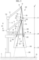
- FIG. 1 is a front view illustrating a composite material cutting apparatus 100 according to the first embodiment of the present disclosure.
- the composite material cutting apparatus 100 of the present embodiment is an apparatus that cuts a long composite material 200.
- the long composite material 200 is, for example, the main wing of an aircraft and is separated from the fuselage of the aircraft.
- the composite material 200 is made of a resin material including a fiber base material.
- the fiber base material is a member in which sheets formed of a reinforced fiber material such as carbon fiber, glass fiber, or the like are laminated over a plurality of layers, for example.
- the fiber base material may be a prepreg into which a resin material is impregnated or partially impregnated in advance or may be a combination of a prepreg and a reinforced fiber material.
- the resin material is, for example, an epoxy resin; a thermosetting resin material such as unsaturated polyester, vinyl ester, phenol, cyanate ester, polyimide, or the like; or a thermoplastic resin such as polyether ether ketone (PEEK), polyethylene terephthalate (PET), polybutylene terephthalate (PBT), nylon 6 (PA6), nylon 66 (PA66), polyphenylene sulfide (PPS), polyetherimide (PEI), polyether ketone ketone (PEKK), or the like.
- PEEK polyether ether ketone
- PET polyethylene terephthalate
- PBT polybutylene terephthalate
- PA6 nylon 6
- PA66 nylon 66
- PPS polyphenylene sulfide
- PEI polyetherimide
- PEKK polyether ketone ketone
- the composite material cutting apparatus 100 of the present embodiment has a support part 10 that supports the composite material 200, a cutting part 20 that cuts the composite material 200, a fixing part 30 that fixes the composite material 200, a gondola 40 that transports the cutting part 20 and the fixing part 30, and an impact absorbing part 50.
- the support part 10 is a device that supports a tip (first end part) 201 of the composite material 200 at an upper part in the vertical direction VD and causes a base end (second end part) 202 of the composite material 200 in the longitudinal direction LD to remain floating over an installation surface S at a lower part in the vertical direction VD.
- the installation surface S is a surface on which the composite material cutting device 100 is installed.
- the axis Z is an axis extending in the vertical direction VD.
- a position Z2 of the base end 202 is a position above a position Z0 of the installation surface S.
- a position Z1 of the tip 201 is a position above the position Z2.
- the support part 10 has a base part 11 installed on the installation surface S, a post 12 fixed to the base part 11 and extending in the vertical direction VD, an arm 13 configured to rotate about a pivot point 12a with respect to the post 12, and a wire winding mechanism 14 fixed to the tip of the arm 13.
- the wire winding mechanism 14 is a mechanism capable of winding up and unwinding a pair of wires 14a, 14b. One ends of the pair of wires 14a, 14b are fixed to a pair of eye bolts 203 attached to the tip 201 of the composite material 200, respectively.
- the wire winding mechanism 14 can be moved from below to above along the vertical direction VD while supporting the composite material 200 by winding up the pair of wires 14a, 14b. Similarly, the wire winding mechanism 14 can support and move the composite material 200 from above to below along the vertical direction VD by winding off the pair of wires 14a, 14b.
- the cutting part 20 is a device that cuts the composite material 200 at a cutting position CP between the tip 201 and the base end 202 of the composite material 200 supported by the support part 10.
- the cutting part 20 is installed on the gondola 40.
- the cutting position CP at which the cutting part 20 cuts the composite material 200 is a position between the position Z1 of the tip 201 and the position Z2 of the base end 202 on the axis Z.
- the cutting part 20 pushes a cutting wire (cutting member) 21 (see Fig. 2 ) against the composite material 200 at the cutting position CP along the horizontal direction HD orthogonal to the vertical direction VD and thereby cuts the composite material 200.
- the cutting part 20 has the cutting wire 21, a primary pulley 22, a plurality of secondary pulleys 23, a pair of rails 24, and a pair of drive mechanisms 25.
- the cutting wire 21 is wound around the primary pulley 22 and the plurality of secondary pulleys 23.
- the primary pulley 22 is rotated by a motor (not illustrated), and thereby the cutting wire 21 wound around the primary pulley 22 and the plurality of secondary pulleys 23 is rotated.
- the pair of rails 24 extend parallel to each other in the horizontal direction HD and support a cutting mechanism in which the cutting wire 21, the primary pulley 22, and the plurality of secondary pulleys 23 are integrated.
- the pair of drive mechanisms 25 are devices that generate drive force to move the cutting mechanism along the horizontal direction HD.
- the cutting mechanism to which drive force is applied by the pair of drive mechanisms 25 moves in a direction approaching the composite material 200 in the horizontal direction HD and thereby pushes the cutting wire 21 against the composite material 200.
- the cutting mechanism reaches a position indicated by the dotted line in Fig. 2 .
- the pair of drive mechanisms 25 retract the cutting mechanism to a position indicated by the solid line in Fig. 2 .
- the fixing part 30 is a device that fixes the composite material 200 so as not to move when the composite material 200 is cut by the cutting part 20.
- the fixing part 30 is installed on the gondola 40.
- the fixing part 30 causes an adsorption member to contact with the surface of the composite material 200, applies suction force to the adsorption member, and thereby fixes the composite material 200 at a constant position.
- the gondola 40 is a device attached movably along the vertical direction VD with respect to the post 12. An operator who operates the cutting part 20 and the fixing part 30 is able to ride in the gondola 40. Further, when operated by the operator, the gondola 40 can move the cutting part 20 and the fixing part 30 to any position along the vertical direction VD. Therefore, the cutting part 20 can set any position in the longitudinal direction LD of the composite material 200 as the cutting position CP.
- the impact absorbing part 50 is a member arranged below the composite material 200 supported by the support part 10 and configured to absorb an impact due to falling of the lower portion of the composite material 200 than the cutting position CP in the vertical direction VD cut off by the cutting part 20.
- FIG. 3 is a flowchart illustrating the composite material cutting method of the present embodiment.
- step S101 (supporting step), a pair of eye bolts 203 are fixed to the tip 201 of the composite material 200 removed from the fuselage of the aircraft, and a pair of wires 14a, 14b are fixed to the pair of eye bolts 203. Thereafter, the wire winding mechanism 14 then winds up the pair of wires 14a and 14b to move the composite material 200 from below to above along the vertical direction VD to the state shown in Fig. 1 .
- step S102 the fixing part 30 fixes the composite material 200 so as not to move when the composite material 200 is cut by the cutting part 20.
- the fixing part 30 causes an adsorption member to contact with the surface of the composite material 200, applies suction force to the adsorption member, and thereby fixes the composite material 200 at a constant position.
- step S103 the cutting part 20 cuts the composite material 200 at the cutting position CP between the tip 201 and the base end 202 of the composite material 200 supported by the support part 10.
- the composite material cutting apparatus 100 can set the cutting position CP at any position on the axis Z.
- the composite material cutting apparatus 100 sets only one position near the intermediate position between the tip 201 and the base end 202 as the cutting position CP and cuts the composite material 200 at the one cutting position CP. Further, for example, when dividing the composite material 200 into three along the longitudinal direction LD, the composite material cutting apparatus 100 sets two positions dividing the extent between the tip 201 and the base end 202 into three as the cutting positions CP. In such a case, the cutting part 20 first cuts the composite material 200 at the cutting position CP near the base end 202 and then cuts the composite material 200 at the cutting position CP near the tip 201.
- the composite material cutting apparatus 100 sets one or a plurality of positions in the vertical direction VD as the cutting positions CP in order to divide the composite material 200 and cuts the composite material 200 at a plurality of cutting positions from the base end 202 to the tip 201. Accordingly, the composite material 200 can be cut in any size.
- the portion lower than the cutting position CP of the vertical direction VD cut off by the cutting part 20 of the composite material 200 falls downward toward the installation surface S along the vertical direction VD due to gravity.
- the impact due to the falling is absorbed.
- noise occurring when the falling portion of the composite material 200 impacts the installation surface S is reduced, and scattering of fragments of the composite material 200 when coming into contact with the installation surface S is prevented.
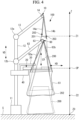
- Fig. 4 is a front view illustrating the first modified example for the composite material cutting apparatus 100 illustrated in Fig. 1 .
- the composite material cutting apparatus 100 of the present modified example does not have the impact absorbing part 50.
- the composite material cutting apparatus 100 of the present modified example has a holding part 60 that holds the lower portion of the composite material 200 than the cutting position CP in the vertical direction VD.
- the holding part 60 of the composite material cutting apparatus 100 of the first modified example is a apparatus that holds the lower portion of the composite material 200 than the cutting position CP in the vertical direction VD cut off by the cutting part 20 so as to maintain the base end 202 of the composite material 200 floating at a lower part in the vertical direction VD.
- the holding part 60 has a bag 61, an arm 62 configured to rotate about a pivot point 12b with respect to the post 12, and a wire winding mechanism 63 fixed to the tip of the arm 62.
- the bag 61 is a bag-like member that accommodates and holds therein the lower portion of the composite material 200 than the cutting position CP in the vertical direction VD.
- the wire winding mechanism 63 is a mechanism capable of winding up and unwinding a pair of wires 63a, 63b. One ends of the pair of wires 63a, 63b are fixed to the upper part end of the bag 61, respectively.
- the wire winding mechanism 63 can support and move the lower portion of the composite material 200 than the cutting position CP, which was cut at the cutting position CP, from above to below in the vertical direction VD by winding off the pair of wires 63a, 63b. Accordingly, the lower portion of the composite material 200 than the cutting position CP, which was cut at the cutting position CP, can be safely lowered onto the installation surface S without falling due to the gravity.
- the composite material 200 indicted by the dotted line in Fig. 4 illustrates the lower portion of the composite material 200 than the cutting position CP lowered onto the installation surface S.
- Fig. 5 is a front view illustrating the second modified example for the composite material cutting apparatus 100 illustrated in Fig. 1 .
- the composite material cutting apparatus 100 of the present modified example does not have the impact absorbing part 50.
- the composite material cutting apparatus 100 of the present modified example has a holding part 70 that holds the lower portion of the composite material 200 than the cutting position CP in the vertical direction VD.
- the holding part 70 of the composite material cutting apparatus 100 of the second modified example is an apparatus that holds the lower portion of the composite material 200 than the cutting position CP in the vertical direction VD cut off by the cutting part 20 so as to maintain the base end 202 of the composite material 200 floating at a lower part in the vertical direction VD.
- the holding part 70 has an arm 71 configured to rotate about the pivot point 12b with respect to the post 12 and a wire winding mechanism 72 fixed to the tip of the arm 71.
- the wire winding mechanism 72 is a mechanism capable of winding up and unwinding a pair of wires (hanging members) 72a, 72b. One end of the pair of wires 72a, 72b is respectively attached to an eye bolt 203 fixed below the cutting position CP of the composite material 200 than the cutting position CP.
- the holding part 70 holds a portion of the composite material 200 cut by the cutting part 20 lower than the cutting position CP in the vertical direction VD by fixing it to a pair of wires 72a, 72b suspended from above in the vertical direction VD and holds the lower portion.
- the wire winding mechanism 72 can be moved from above to below along the vertical direction VD while supporting the lower portion of the cutting position CP of the composite material 200 cut at the cutting position CP by winding out the pair of wires 72a, 72b.
- the composite material 200 shown as a dotted line in FIG. 5 shows a portion where the cutting position CP of the composite material 200 is lower than the portion where it is lowered on the installation surface S.
- Fig. 6 is a front view illustrating the third modified example for the composite material cutting apparatus 100 illustrated in Fig. 1 .
- the composite material cutting apparatus 100 of the present modified example does not have the impact absorbing part 50.
- the composite material cutting apparatus 100 of the present modified example has a wire (linear member) 80 and a plurality of eye bolts (insertion members) 204.
- the wire 80 extends from a vertical direction VD to an inclined direction ID and is a metallic liner member having one end fixed to an installation surface S on which the support part 10 is installed. The other end of the wire 80 is fixed to the tip of the arm 13.
- the plurality of eye bolts 204 are members fixed to both below and above the cutting position CP of the composite material 200 in the vertical direction VD, and an insertion hole for inserting the wire 80 is formed. As shown in Fig. 6 , the wire 80 is inserted into eye bolt 204 secured to the composite material 200.
- the lower portion of the composite material 200 than the cutting position CP in the vertical direction VD cut off by the cutting part 20 is guided in the inclination direction ID toward the installation surface S along the wire 80.
- the composite material 200 illustrated by the dotted line in Fig. 6 illustrates the lower portion of the composite material 200 than the cutting position CP lowered onto the installation surface S.
- the support part 10 can support the tip 201 of the long composite material 200 at the upper part in the vertical direction VD and cause the base end 202 to remain floating at a lower part in the vertical direction VD.
- the cutting part 20 then cuts the composite material at the cutting position CP between the tip 201 and the base end 202 of the composite material supported by the support part 10. Accordingly, it is possible to cut the composite material 200 without transporting the long composite material 200 to a dismantling site and reduce the cost in dismantling the long composite material 200.
- the lower portion of the composite material 200 than the cutting position CP in the vertical direction VD cut off by the cutting part 20 is held by the holding part 60, 70, and the base end 202 can be maintained floating at a lower part in the vertical direction VD. It is thus possible to prevent danger due to falling of the lower portion of the composite material 200 than the cutting position CP cut off by the cutting part 20.
- the composite material cutting apparatus 100 of the present embodiment since the lower portion of the composite material 200 lower than the vertical cutting position CP in the vertical direction VD cut off by the cutting part 20 is housed in the bag 61, the danger due to the fall of the lower portion of the composite material 200 lower than the cutting position CP cut off by the cutting part 20 can be prevented.
- the impact due to falling of the lower portion of the composite material 200 than the cutting position CP in the vertical direction VD cut off by the cutting part 20 is absorbed by the impact absorbing part 50. It is thus possible to suppress danger due to falling of the lower portion of the composite material 200 than the cutting position CP cut off by the cutting part 20.
- the lower portion of the composite material than the cutting position CP in the vertical direction VD cut off by the cutting part 20 is guided in the inclination direction ID along the inclination direction ID in which the wire 80 inserted in the insertion hole of the eye bolts 204 extends, and the lower portion then reaches the installation surface S.
- the composite material 200 collides with the installation surface S when the cut composite material 200 reaches the installation surface S, the composite material 200 is caught by the wire 80 via the eye bolts 204. It is thus possible to prevent danger of scattering of the cut composite material 200 due to impact received from the installation surface S after the cut composite material 200 reached the installation surface S.
- Fig. 7 is a front view showing a composite material cutting apparatus 100A according to the second embodiment of the present disclosure.
- the composite material cutting apparatus 100A of this embodiment is an apparatus for cutting the long composite material 200A.
- the long composite material 200A is a blade used for renewable energy power generation and is, for example, a blade for a wind turbine or tidal power generation or the like.
- the long composite material 200A is attached to a nacelle fixed to the post 301 installed on the installation surface S.
- the composite material 200A is made of a resin material including a fiber base material.
- the fiber base material or the resin material are the same as those in the first embodiment, and the description thereof will be omitted below.
- the composite material cutting apparatus 100A of the present embodiment has a hub (support part) 10A that supports the composite material 200A, a cutting part 20A that cuts the composite material 200A, a fixing part 30A that fixes the composite material 200A, a gondola 40A that transports the cutting part 20A and the fixing part 30A, and the impact absorbing part 50A.
- the hub 10A is attached rotatably to a nacelle 302 and is a device that supports a base end (first end part) 201A of the composite material 200A at the upper part in the vertical direction VD and causes a tip (second end part) 202A of the composite material 200A in the longitudinal direction LD to remain floating over the installation surface S at a lower part in the vertical direction VD.
- the installation surface S is a surface on which the composite material cutting apparatus 100A is installed.
- the axis Z is an axis extending in the vertical direction VD.
- the position Z2 of the tip 202A is a position above the position Z0 of the installation surface S.
- the position Z1 of the base end 201A is a position above the position Z2.
- the cutting part 20A is a device that cuts the composite material 200A at the cutting position CP between the base end 201A and the tip 202A of the composite material 200A supported by the hub 10A.
- the cutting part 20A is installed on the gondola 40A.
- the cutting position CP at which the cutting part 20A cuts the composite material 200A is a position between the position Z1 of the base end 201A and the position Z2 of the tip 202A in the axis Z.
- the cutting part 20A pushes a cutting wire (not illustrated) against the composite material 200A at the cutting position CP along the horizontal direction HD orthogonal to the vertical direction VD and thereby cuts the composite material 200A.
- the configuration of the cutting part 20A is the same as that illustrated in Fig. 2 of the first embodiment.
- the fixing part 30A is a device that fixes the composite material 200A so as not to move when the composite material 200A is cut by the cutting part 20A.
- the fixing part 30A is installed on the gondola 40A.
- the fixing part 30A causes an adsorption member to contact with the surface of the composite material 200A, applies suction force to the adsorption member, and thereby fixes the composite material 200A at a constant position.
- the gondola 40A is a device attached movably along the vertical direction VD with respect to the nacelle 302.
- the operator who operates the cutting part 20A and the fixing part 30A is able to ride in the gondola 40A. Further, when operated by the operator, the gondola 40A can move the cutting part 20A and the fixing part 30A to any position along the vertical direction VD. Therefore, the cutting part 20A can set any position in the longitudinal direction LD of the composite material 200A as the cutting position CP.
- the impact absorbing part 50A is a member arranged below the composite material 200A supported by the hub 10A and configured to absorb an impact due to falling of the lower portion of the composite material 200A than the cutting position CP in the vertical direction VD cut off by the cutting part 20A.
- the impact due to the falling is absorbed.
- noise occurring when the falling portion of the composite material 200A impacts the installation surface S is reduced, and scattering of fragments of the composite material 200A when coming into contact with the installation surface S is prevented.
- Fig. 8 is a front view illustrating the first modified example for the composite material cutting apparatus 100A illustrated in Fig. 7 .
- the composite material cutting apparatus 100A of the present modified example does not have the impact absorbing part 50A.
- the composite material cutting apparatus 100A of the present modified example has a holding part 60A that holds the lower portion of the composite material 200A than the cutting position CP in the vertical direction VD.
- the holding part 60A of the composite material cutting apparatus 100A of the first modified example is an apparatus that holds the lower part of the composite material 200A than the cutting position CP of the vertical direction VD cut off by the cutting part 20A so that the tip 202A of the composite material 200A remains floating on a lower part of the vertical direction VD.
- the holding part 60A has a bag 61A, an arm 62A configured to rotate about a pivot point 64Aa with respect to the post 64A, and a wire winding mechanism 63A fixed to the tip of the arm 62A.
- the bag 61A is a bag-like member that holds a portion of the composite material 200A below the cutting position CP in the vertical direction VD.
- the wire winding mechanism 63A is a mechanism capable of winding up and unwinding a pair of wires 63Aa, 63Ab. One end of the pair of wires 63Aa and 63Ab is fixed to the upper end of the bag 61A, respectively.
- the wire winding mechanism 63A can support and move a portion of the composite material 200A cut at the cutting position CP, lower than the cutting position CP in the vertical direction VD by winding off the pair of wires 63Aa, 63Ab.
- the portion of the composite material 200A cut at the cutting position CP lower than the cutting position CP can be safely lowered to the installation surface S without falling due to the gravity.
- Fig. 9 is a front view illustrating the second modified example for the composite material cutting apparatus 100A illustrated in Fig. 7 .
- the composite material cutting apparatus 100A of the present modified example does not have the impact absorbing part 50A.
- the composite material cutting apparatus 100A of the present modified example has a holding part 70A that holds the lower portion of the composite material 200A than the cutting position CP in the vertical direction VD.
- the holding part 70A of the composite material cutting apparatus 100A of the second modified example is an apparatus that holds the lower portion of the composite material 200A than the cutting position CP in the vertical direction VD cut off by the cutting part 20A so as to maintain the tip 202A of the composite material 200A floating at a lower part in the vertical direction VD.
- the holding part 70A has an arm 71A configured to rotate about a pivot point 73Aa with respect to a post 73A and a wire winding mechanism 72A fixed to the tip of the arm 71A.
- the wire winding mechanism 72A is a mechanism capable of winding up and unwinding a pair of wires (suspension members) 72Aa and 72Ab.
- One ends of the pair of wires 72Aa, 72Ab are attached respectively to the eye bolts 203A fixed to the lower portion of the composite material 200A than the cutting position CP.
- the holding part 70A fixes the lower portion of the composite material 200A than the cutting position CP in the vertical direction VD, which was cut off by the cutting part 20A, to the pair of wires 72Aa, 72Ab suspended from above in the vertical direction VD and holds the lower portion.
- the wire winding mechanism 72A can support and move the lower portion of the composite material 200A cut at the cutting position CP lower than the cutting position CP in the vertical direction VD by winding off the pair of wires 72Aa, 72Ab. Accordingly, the lower portion of the composite material 200A than the cutting position CP, which was cut at the cutting position CP, can be safely lowered onto the installation surface S without falling due to the gravity.
- the composite material 200A indicted by the dotted line in Fig. 9 illustrates the lower portion of the composite material 200A than the cutting position CP lowered onto the installation surface S.
- Fig. 10 is a front view illustrating the third modified example for the composite material cutting apparatus 100A illustrated in Fig. 7 .
- the composite material cutting device 100A of the present modified example does not have the impact absorbing part 50A.
- the composite material cutting apparatus 100A of the present modified example has a wire (linear member) 80A and a plurality of eye bolts (insertion members) 204A.
- the wire 80A is a metal linear member extending in an inclination direction ID inclined from the vertical direction VD and having one end fixed to eye bolts 205 attached to the installation surface S on which the support part 10A is installed. The other end of the wire 80A is fixed to the eye bolts 205 attached to the post 301.
- the plurality of eye bolts 204A are members fixed to both below and above the cutting position CP of the composite material 200A in the vertical direction VD, and an insertion hole is formed into which the wire 80A is inserted. As shown in FIG. 10 , the wire 80A is inserted in the eye bolts 204A fixed to the composite material 200A.
- the lower portion lower than the cutting position CP of the vertical direction VD cut by the cutting part 20A of the composite material 200 is guided along the wire 80A toward the installation surface S in the inclined direction ID.
- the composite material 200A shown as a dotted line in Fig. 10 represents a portion below the cutting position CP of the composite material 200A lowered to the installation surface S.
- the hub 10A can support the base end 201A of the long composite material 200 at the upper part in the vertical direction VD and cause the tip 202A to remain floating at a lower part in the vertical direction VD.
- the cutting part 20A then cuts the composite material 200A at the cutting position CP between the base end 201A and the tip 202A of the composite material supported by the hub 10A. Accordingly, it is possible to cut the composite material 200A without transporting the long composite material 200A to a dismantling site and reduce the cost in dismantling the long composite material 200A.
- the lower portion of the composite material 200A than the cutting position CP in the vertical direction VD cut off by the cutting part 20A is held by the holding part 60A, 70A, and the tip 202A can be maintained floating at a lower part in the vertical direction VD. It is thus possible to prevent danger due to falling of the lower portion of the composite material 200A than the cutting position CP cut off by the cutting part 20A.
- the composite material cutting apparatus 100A of the present embodiment since the portion below the vertical direction VD in the vertical direction of the cutting position CP of the composite material 200A cut by the cutting part 20A is housed in the bag 61A, danger due to falling of the portion lower than portion the cutting position CP cut by the cutting part 20A of the composite material 200A can be prevented.
- the impact due to falling of the lower portion of the composite material 200A than the cutting position CP in the vertical direction VD cut off by the cutting part 20A is absorbed by the impact absorbing part 50A. It is thus possible to suppress danger due to falling of the lower portion of the composite material 200A than the cutting position CP cut off by the cutting part 20A.
- the lower portion of the composite material 200A than the cutting position CP in the vertical direction VD cut off by the cutting part 20A is guided in the inclination direction ID along the inclination direction ID in which the wire 80A inserted in the insertion hole of the eye bolts 204A extends, and the lower portion then reaches the installation surface S.
- the composite material 200A collides with the installation surface S when the cut composite material 200A reaches the installation surface S, the composite material 200A is caught by the wire 80A via the eye bolts 204A. It is thus possible to prevent danger of scattering of the cut composite material 200A due to impact received from the installation surface S after the cut composite material 200A reached the installation surface S.
- Fig. 11 is a front view illustrating the composite material cutting apparatus 100B according to the third embodiment of the present disclosure.
- the composite material cutting apparatus 100B of the present embodiment is an apparatus that cuts a long composite material 200B.
- the long composite material 200B is, for example, the main wing of an aircraft and is removed from the fuselage of the aircraft.
- the composite material cutting apparatus 100B of the present embodiment has a support part 10B that supports the composite material 200B, a cutting part 20B that cuts the composite material 200B, a fixing part 30B that fixes the composite material 200B, a gondola 40B that transports the cutting part 20B and the fixing part 30B, a crushing device 90B, and a belt conveyer 95B.
- the support part 10B is a device that supports a tip (first end part) 201B of the composite material 200B at the upper part in the vertical direction VD and causes a base end (second end part) 202B of the composite material 200B in the longitudinal direction LD to remain floating over the installation surface S at a lower part in the vertical direction VD.
- the installation surface S is a surface on which the composite material cutting apparatus 100B is installed.
- the axis Z is an axis extending in the vertical direction VD.
- the position Z2 of the base end 202B is a position above the position Z0 of the installation surface S.
- the position Z1 of the tip 201B is a position above the position Z2.
- the support part 10B has a base part 11B provided on the installation surface S, a post 12B fixed to the base part 11B and extending in the vertical direction VD, an arm 13B configured to rotate about the base point 12Ba with respect to the post 12B, and a wire winding mechanism 14B fixed to the tip of the arm 13B.
- the wire winding mechanism 14B is a mechanism capable of winding up and unwinding a pair of wires 14Baand 14Bb is respectively fixed to a pair of eye bolts 203B attached to the tip end 201B of the composite material 200B, respectively.
- the wire winding mechanism 14B can support and move the composite material 200B from below to above in the vertical direction VD by winding up the pair of wires 14Ba, 14Bb. Similarly, the wire winding mechanism 14B can support and move the composite material 200B from above to below in the vertical direction VD by winding off the pair of wires 14Ba, 14Bb.
- the cutting part 20B is a device that cuts the composite material 200B at a cutting position CP between the tip 201B and the base end 202B of the composite material 200B supported by the support part 10B.
- the cutting part 20B is installed on the gondola 40B.
- the cutting position CP at which the cutting part 20B cuts the composite material 200B is a position between the position Z1 of the tip 201B and the position Z2 of the base end 202B on the axis Z.
- the cutting part 20B pushes a cutting wire (cutting member) 21B (see Fig. 12 ) against the composite material 200B at the cutting position CP along the horizontal direction HD orthogonal to the vertical direction VD and thereby cuts the composite material 200B.
- the cutting part 20B has the cutting wire 21B, a primary pulley 22B, a plurality of secondary pulleys 23B, a pair of rails 24B, and a pair of drive mechanisms 25B.
- the cutting wire 21B is wound around the primary pulley 22B and the plurality of secondary pulleys 23B.
- the primary pulley 22B is rotated by a motor (not illustrated), and thereby the cutting wire 21B wound around the primary pulley 22B and the plurality of secondary pulleys 23B is rotated.
- the pair of rails 24B extend parallel to each other in the horizontal direction HD and support a cutting mechanism in which the cutting wire 21B, the primary pulley 22B, and the plurality of secondary pulleys 23B are integrated.
- the pair of drive mechanisms 25B are devices that generate drive force to move the cutting mechanism along the horizontal direction HD.
- the cutting mechanism to which drive force is applied by the pair of drive mechanisms 25B moves in a direction approaching the composite material 200B in the horizontal direction HD and thereby pushes the cutting wire 21B against the composite material 200B.
- the cutting mechanism When the cutting mechanism has completely cut the composite material 200B at the cutting position CP, the cutting mechanism reaches a position indicated by the dotted line in Fig. 11 . After completely cutting the composite material 200B at the cutting position CP, the pair of drive mechanisms 25B retract the cutting mechanism.
- the cutting part 20B of the present embodiment is arranged in a shape along which the cutting wire 21B runs in a zigzag manner so that the cutting wire 21B passes through multiple positions in the horizontal direction HD.
- the cutting part 20B moves from below to above along the vertical direction VD in a state illustrated in Fig. 12 , the composite material 200B is cut along the vertical direction VD at a plurality of positions in the horizontal direction HD.
- portions cut along the vertical direction VD at a plurality of positions in the horizontal direction HD become a plurality of small pieces and fall to the crushing device 90B.
- the cutting part 20B cuts the composite material 200B so that the size of each small piece becomes a size that is smaller than or equal to the maximum size that can be crushed by the crushing device 90B.
- the cutting part 20B moves the cutting wire 21B along both the horizontal direction HD and the vertical direction VD and divides the composite material 200B into pieces of the maximum size or smaller that can be crushed by the crushing device 90B. Specifically, the cutting part 20B moves the position of the tip of the cutting part 20B in the following order, as illustrated in Fig. 11 .
- the position of the tip of the cutting part 20B is moved along the horizontal direction HD from position P0 to position P1 and then moved from position P1 to position P2 along the vertical direction VD.
- the position of the tip of the cutting part 20B is moved from position P2 to position P3 along the horizontal direction HD. During the motion from position P2 to position P3, small pieces of the composite material 200B fall to the crushing device 90B.
- position P3 to position P5 is the same as the motion from position P0 to position P3, and the order is position P3, position P2, position P4, and position P5. Then, the position of the tip of the cutting part 20B is moved along the horizontal direction HD and the vertical direction VD in the order of position P5, position P4, position P6, position P7, position P6, position P8, position P9, position P8, position P10, and position P11.
- the fixing part 30B is a device that fixes the composite material 200B so as not to move when the composite material 200B is cut by the cutting part 20B.
- the fixing part 30B is installed on the gondola 40B.
- the fixing part 30B causes an adsorption member to contact with the surface of the composite material 200B, applies suction force to the adsorption member, and thereby fixes the composite material 200B at a constant position.
- the gondola 40B is a device attached movably along the vertical direction VD with respect to the post 12B.
- the operator who operates the cutting part 20B and the fixing part 30B is able to ride in the gondola 40B. Further, when operated by the operator, the gondola 40B can move the cutting part 20B and the fixing part 30B to any position along the vertical direction VD. Therefore, the cutting part 20B can set any position in the longitudinal direction LD of the composite material 200B as the cutting position CP.
- the crushing device 90B is a device that crushes the composite material 200B cut off by the cutting part 20B.
- the composite material 200B crushed by the crushing device 90B is supplied to the belt conveyer 95B and conveyed to a disposal site (not illustrated) by the belt conveyer 95B.
- the cutting wire 21B is moved along both the horizontal direction HD and the vertical direction VD to divide the composite material 200B into pieces of a predetermined size or smaller (for example, smaller than or equal to the maximum size that can be crushed by the crushing device 90B), and thereby the transportation cost of the cut composite material 200B can be reduced.
- a wet wire saw may be employed.
- a laser cutting machine or a water jet cutting machine may be employed.
- the cutting parts 20, 20A, 20B are operated by an operator in the above description, other forms may be employed.
- the cutting part 20, 20A, 20B may be controlled by a control signal transmitted from a control device (not illustrated).
- a control device not illustrated
- the composite material cutting apparatus according to the embodiment described above is understood as follows, for example.
- the composite material cutting apparatus (100) includes: a support part (10) for supporting a first end part (201) in a longitudinal direction (LD) of a long composite material (200) made of a resin material including a fiber base material at the upper part in the vertical direction (VD) and cause a second end part (202) in the longitudinal direction of the composite material to remain floating at a lower part in the vertical direction; and a cutting part (20) configured to cut the composite material at a cutting position (CP) between the first end part and the second end part of the composite material supported by the support part.
- a support part (10) for supporting a first end part (201) in a longitudinal direction (LD) of a long composite material (200) made of a resin material including a fiber base material at the upper part in the vertical direction (VD) and cause a second end part (202) in the longitudinal direction of the composite material to remain floating at a lower part in the vertical direction
- a cutting part (20) configured to cut the composite material at a cutting position (CP) between the first end part and the second
- the support part can support the first end part of a long composite material made of a resin material including a fiber base material at the upper part in the vertical direction and cause the second end part thereof to remain floating at a lower part in the vertical direction.
- the cutting part then cuts the composite material at a cutting position between the first end part and the second end part of the composite material supported by the support part. Accordingly, it is possible to cut the composite material without transporting the long composite material to a dismantling site and reduce the cost in dismantling the long composite material.
- the composite material cutting apparatus may be configured to include a holding part (60, 70) configured to hold the lower portion of the composite material than the cutting position in the vertical direction cut off by the cutting part so as to maintain the second end part floating at a lower part in the vertical direction.
- a holding part 60, 70
- the lower portion of the composite material than the cutting position in the vertical direction cut off by the cutting part is held by the holding part, and the second end part can be maintained floating at a lower part in the vertical direction. It is thus possible to prevent danger due to falling of the lower portion of the composite material than the cutting position cut off by the cutting part.
- the composite material cutting apparatus of the above configuration may be formed such that the holding part accommodates, in a bag (61), and holds the lower portion of the composite material than the cutting position in the vertical direction cut off by the cutting part, and the bag is suspended from above in the vertical direction.
- the composite material cutting apparatus of the present form since the lower portion of the composite material than the cutting position in the vertical direction cut off by the cutting part is accommodated in the bag, it is possible to prevent danger due to falling of the lower portion of the composite material than the cutting position cut off by the cutting part.
- the composite material cutting apparatus of the above configuration may have a form such that the holding part fixes, to a suspending member, and holds the lower portion of the composite material than the cutting position in the vertical direction cut off by the cutting part, and the suspending member is suspended from above in the vertical direction.
- the composite material cutting apparatus of the present form since the lower portion of the composite material than the cutting position in the vertical direction cut off by the cutting part is fixed to the suspending member, it is possible to prevent danger due to falling of the lower portion of the composite material than the cutting position cut off by the cutting part.
- the composite material cutting apparatus may be configured to include an impact absorbing part (50) arranged below the composite material (200) supported by the support part and configured to absorb an impact due to falling of the lower portion of the composite material than the cutting position in the vertical direction cut off by the cutting part.
- an impact absorbing part (50) arranged below the composite material (200) supported by the support part and configured to absorb an impact due to falling of the lower portion of the composite material than the cutting position in the vertical direction cut off by the cutting part.
- the impact caused by the falling of the composite material on the lower side in the vertical direction than the cutting position cut by the cutting part is absorbed by the impact absorbing part.
- the danger due to the falling of the lower part of the composite material can be suppressed rather than the cutting position cut by the cutting part.
- the composite material cutting apparatus may be configured to include: a linear member extending in an inclination direction inclined from the vertical direction and having one end fixed to an installation surface on which the support part is installed; and an insertion member fixed below, in the vertical direction, the cutting position of the composite material and having an insertion hole formed in the insertion member, the linear member being inserted in the insertion hole, and may be configured such that the lower portion of the composite material than the cutting position in the vertical direction cut off by the cutting part is guided in the inclination direction toward the installation surface along the linear member.
- the lower portion of the composite material than the cutting position in the vertical direction cut off by the cutting part is guided in the inclination direction along the inclination direction in which the linear member inserted in the insertion hole of the insertion members extends, and the lower portion then reaches the installation surface.
- the composite material collides with the installation surface when the cut composite material reaches the installation surface, the composite material is caught by the linear member via the insertion members. It is thus possible to prevent danger of scattering of the cut composite material due to impact received from the installation surface after the cut composite material reached the installation surface.
- the composite material cutting apparatus may be configured such that the cutting part cuts the composite material by pushing a cutting member (21) against the composite material at the cutting position along the horizontal direction (HD).
- the composite material cutting apparatus of the present configuration it is possible to push a cutting member against the composite material at the cutting position along the horizontal direction and thereby cut the composite material.
- the composite material cutting apparatus of the above configuration may be formed such that the cutting part moves the cutting member along both the horizontal direction and the vertical direction to divide the composite material into pieces of a predetermined size or smaller.
- the cutting member is moved along both the horizontal direction and the vertical direction to divide the composite material into pieces of a predetermined size or smaller (for example, smaller than or equal to the maximum size that can be crushed by the crushing device), and thereby the transportation cost of the cut composite material can be reduced.
- the composite material cutting method according to the present embodiment described above is understood as follows, for example.
- the composite material cutting method includes: a supporting step (S101) of supporting a first end part of a long composite material made of a resin material including a fiber base material at the upper part in the vertical direction and causing a second end part in the longitudinal direction of the composite material to remain floating at a lower part in the vertical direction; and a cutting step (S103) of cutting the composite material at a cutting position between the first end part and the second end part of the composite material supported by the supporting step.
- the supporting step can support the first end part of a long composite material made of a resin material including a fiber base material at the upper part in the vertical direction and cause the second end part thereof to remain floating at a lower part in the vertical direction.
- the cutting step then cuts the composite material at a cutting position between the first end part and the second end part of the composite material supported by the support part. Accordingly, it is possible to cut the composite material without transporting the long composite material to a dismantling site and reduce the cost in dismantling the long composite material.
Landscapes
- Life Sciences & Earth Sciences (AREA)
- Forests & Forestry (AREA)
- Engineering & Computer Science (AREA)
- Mechanical Engineering (AREA)
- Reinforced Plastic Materials (AREA)
- Working Measures On Existing Buildindgs (AREA)
Abstract
Description
- The present disclosure relates to a composite material cutting apparatus and a composite material cutting method.
- Conventionally, technologies to integrally mold the framework structure of a main wing of an aircraft by using a fiber reinforced resin composite material are known (for example, see Patent Literature 1). Main wings of an aircraft are attached to a fuselage together with other components. Further, when an aircraft is dismantled, main wings are removed from the fuselage and transported to a dismantling site. The main wings transported to the dismantling site are cut or disassembled into a predetermined size by an operator and crushed by a crusher.
- [PTL 1]
Japanese Patent Application Laid-Open No. 2001-48097 - However, transportation of a long composite material such as a main wing of an aircraft to a dismantling site will requires a large effort and also increase the cost required for the transportation.
- The present disclosure has been made in view of such circumstances and intends to provide a composite material cutting apparatus and a composite material cutting method that can reduce the cost in dismantling a long composite material.
- The composite material cutting apparatus according to the present disclosure is provided with a support part for supporting a first end part in the longitudinal direction of a long composite material made of a resin material including a fiber base material at an upper part in the vertical direction, and for making the second end part in the longitudinal direction of the composite material to remain floating at a lower part in the vertical direction. The cutting part is configured to cut the composite material at a cutting position between the first and the second end parts of the composite material supported by the support part.
- A composite material cutting method according to the present disclosure includes: a supporting step of supporting a first end part in a longitudinal direction of a long composite material made of a resin material including a fiber base material at an upper part in the vertical direction and causing a second end part in the longitudinal direction of the composite material to remain floating at a lower part in the vertical direction; and a cutting step of cutting the composite material at a cutting position between the first end part and the second end part of the composite material supported by the support part.
- According to the present disclosure, a composite material cutting apparatus and a composite material cutting method that can reduce the cost in dismantling a long composite material can be provided.
-
- [
Fig. 1 ]
Fig. 1 is a front view illustrating a composite material cutting apparatus according to a first embodiment of the present disclosure. - [
Fig. 2 ]
Fig. 2 is a sectional view viewed along an arrow A-A of the composite material cutting apparatus illustrated inFig. 1 . - [
Fig. 3 ]
Fig. 3 is a flowchart illustrating a composite material cutting method according to the first embodiment of the present disclosure. - [
Fig. 4 ]
Fig. 4 is a front view illustrating a first modified example for the composite material cutting apparatus illustrated inFig. 1 . - [
Fig. 5 ]
Fig. 5 is a front view illustrating a second modified example for the composite material cutting apparatus illustrated inFig. 1 . - [
Fig. 6 ]
Fig. 6 is a front view illustrating a third modified example for the composite material cutting apparatus illustrated inFig. 1 . - [
Fig. 7 ]
Fig. 7 is a front view illustrating a composite material cutting apparatus according to a second embodiment of the present disclosure. - [
Fig. 8 ]
Fig. 8 is a front view illustrating a first modified example for the composite material cutting apparatus illustrated inFig. 7 . - [
Fig. 9 ]
Fig. 9 is a front view illustrating a second modified example for the composite material cutting apparatus illustrated inFig. 7 . - [
Fig. 10 ]
Fig. 10 is a front view illustrating a third modified example for the composite material cutting apparatus illustrated inFig. 7 . - [
Fig. 11 ]
Fig. 11 illustrates a composite material cutting apparatus according to a third embodiment of the present disclosure. - [
Fig. 12 ]
Fig. 12 is a sectional view viewed along an arrow B-B of the composite material cutting apparatus illustrated inFig. 11 . - A composite
material cutting apparatus 100 according to the first embodiment of the present disclosure will be described below with reference to the drawings.Fig. 1 is a front view illustrating a compositematerial cutting apparatus 100 according to the first embodiment of the present disclosure. The compositematerial cutting apparatus 100 of the present embodiment is an apparatus that cuts a longcomposite material 200. The longcomposite material 200 is, for example, the main wing of an aircraft and is separated from the fuselage of the aircraft. - The
composite material 200 is made of a resin material including a fiber base material. The fiber base material is a member in which sheets formed of a reinforced fiber material such as carbon fiber, glass fiber, or the like are laminated over a plurality of layers, for example. Further, the fiber base material may be a prepreg into which a resin material is impregnated or partially impregnated in advance or may be a combination of a prepreg and a reinforced fiber material. - The resin material is, for example, an epoxy resin; a thermosetting resin material such as unsaturated polyester, vinyl ester, phenol, cyanate ester, polyimide, or the like; or a thermoplastic resin such as polyether ether ketone (PEEK), polyethylene terephthalate (PET), polybutylene terephthalate (PBT), nylon 6 (PA6), nylon 66 (PA66), polyphenylene sulfide (PPS), polyetherimide (PEI), polyether ketone ketone (PEKK), or the like.
- As illustrated in
Fig. 1 , the compositematerial cutting apparatus 100 of the present embodiment has asupport part 10 that supports thecomposite material 200, acutting part 20 that cuts thecomposite material 200, afixing part 30 that fixes thecomposite material 200, agondola 40 that transports thecutting part 20 and thefixing part 30, and animpact absorbing part 50. - The
support part 10 is a device that supports a tip (first end part) 201 of thecomposite material 200 at an upper part in the vertical direction VD and causes a base end (second end part) 202 of thecomposite material 200 in the longitudinal direction LD to remain floating over an installation surface S at a lower part in the vertical direction VD. The installation surface S is a surface on which the compositematerial cutting device 100 is installed. InFig. 1 , the axis Z is an axis extending in the vertical direction VD. On the axis Z, a position Z2 of thebase end 202 is a position above a position Z0 of the installation surface S. On the axis Z, a position Z1 of thetip 201 is a position above the position Z2. - The
support part 10 has abase part 11 installed on the installation surface S, apost 12 fixed to thebase part 11 and extending in the vertical direction VD, anarm 13 configured to rotate about apivot point 12a with respect to thepost 12, and awire winding mechanism 14 fixed to the tip of thearm 13. Thewire winding mechanism 14 is a mechanism capable of winding up and unwinding a pair ofwires wires eye bolts 203 attached to thetip 201 of thecomposite material 200, respectively. - The
wire winding mechanism 14 can be moved from below to above along the vertical direction VD while supporting thecomposite material 200 by winding up the pair ofwires wire winding mechanism 14 can support and move thecomposite material 200 from above to below along the vertical direction VD by winding off the pair ofwires - The
cutting part 20 is a device that cuts thecomposite material 200 at a cutting position CP between thetip 201 and thebase end 202 of thecomposite material 200 supported by thesupport part 10. Thecutting part 20 is installed on thegondola 40. The cutting position CP at which the cuttingpart 20 cuts thecomposite material 200 is a position between the position Z1 of thetip 201 and the position Z2 of thebase end 202 on the axis Z. - As illustrated in
Fig. 1 , the cuttingpart 20 pushes a cutting wire (cutting member) 21 (seeFig. 2 ) against thecomposite material 200 at the cutting position CP along the horizontal direction HD orthogonal to the vertical direction VD and thereby cuts thecomposite material 200. As illustrated inFig. 2 , the cuttingpart 20 has thecutting wire 21, aprimary pulley 22, a plurality ofsecondary pulleys 23, a pair ofrails 24, and a pair ofdrive mechanisms 25. - The
cutting wire 21 is wound around theprimary pulley 22 and the plurality ofsecondary pulleys 23. Theprimary pulley 22 is rotated by a motor (not illustrated), and thereby thecutting wire 21 wound around theprimary pulley 22 and the plurality ofsecondary pulleys 23 is rotated. The pair ofrails 24 extend parallel to each other in the horizontal direction HD and support a cutting mechanism in which thecutting wire 21, theprimary pulley 22, and the plurality ofsecondary pulleys 23 are integrated. - The pair of
drive mechanisms 25 are devices that generate drive force to move the cutting mechanism along the horizontal direction HD. The cutting mechanism to which drive force is applied by the pair ofdrive mechanisms 25 moves in a direction approaching thecomposite material 200 in the horizontal direction HD and thereby pushes thecutting wire 21 against thecomposite material 200. When the cutting mechanism has completely cut thecomposite material 200 at the cutting position CP, the cutting mechanism reaches a position indicated by the dotted line inFig. 2 . After completely cutting thecomposite material 200 at the cutting position CP, the pair ofdrive mechanisms 25 retract the cutting mechanism to a position indicated by the solid line inFig. 2 . - The fixing
part 30 is a device that fixes thecomposite material 200 so as not to move when thecomposite material 200 is cut by the cuttingpart 20. The fixingpart 30 is installed on thegondola 40. For example, the fixingpart 30 causes an adsorption member to contact with the surface of thecomposite material 200, applies suction force to the adsorption member, and thereby fixes thecomposite material 200 at a constant position. - The
gondola 40 is a device attached movably along the vertical direction VD with respect to thepost 12. An operator who operates the cuttingpart 20 and the fixingpart 30 is able to ride in thegondola 40. Further, when operated by the operator, thegondola 40 can move the cuttingpart 20 and the fixingpart 30 to any position along the vertical direction VD. Therefore, the cuttingpart 20 can set any position in the longitudinal direction LD of thecomposite material 200 as the cutting position CP. - The
impact absorbing part 50 is a member arranged below thecomposite material 200 supported by thesupport part 10 and configured to absorb an impact due to falling of the lower portion of thecomposite material 200 than the cutting position CP in the vertical direction VD cut off by the cuttingpart 20. - A composite material cutting method for cutting the
composite material 200 by using the compositematerial cutting apparatus 100 of the present embodiment will now be described with reference to the drawings.Fig. 3 is a flowchart illustrating the composite material cutting method of the present embodiment. - In step S101 (supporting step), a pair of
eye bolts 203 are fixed to thetip 201 of thecomposite material 200 removed from the fuselage of the aircraft, and a pair ofwires eye bolts 203. Thereafter, thewire winding mechanism 14 then winds up the pair ofwires composite material 200 from below to above along the vertical direction VD to the state shown inFig. 1 . - In step S102 (fixing step), the fixing
part 30 fixes thecomposite material 200 so as not to move when thecomposite material 200 is cut by the cuttingpart 20. For example, the fixingpart 30 causes an adsorption member to contact with the surface of thecomposite material 200, applies suction force to the adsorption member, and thereby fixes thecomposite material 200 at a constant position. - In step S103 (cutting step), the cutting
part 20 cuts thecomposite material 200 at the cutting position CP between thetip 201 and thebase end 202 of thecomposite material 200 supported by thesupport part 10. The compositematerial cutting apparatus 100 can set the cutting position CP at any position on the axis Z. - For example, when dividing the
composite material 200 into two along the longitudinal direction LD, the compositematerial cutting apparatus 100 sets only one position near the intermediate position between thetip 201 and thebase end 202 as the cutting position CP and cuts thecomposite material 200 at the one cutting position CP. Further, for example, when dividing thecomposite material 200 into three along the longitudinal direction LD, the compositematerial cutting apparatus 100 sets two positions dividing the extent between thetip 201 and thebase end 202 into three as the cutting positions CP. In such a case, the cuttingpart 20 first cuts thecomposite material 200 at the cutting position CP near thebase end 202 and then cuts thecomposite material 200 at the cutting position CP near thetip 201. - In such a way, the composite
material cutting apparatus 100 sets one or a plurality of positions in the vertical direction VD as the cutting positions CP in order to divide thecomposite material 200 and cuts thecomposite material 200 at a plurality of cutting positions from thebase end 202 to thetip 201. Accordingly, thecomposite material 200 can be cut in any size. - The portion lower than the cutting position CP of the vertical direction VD cut off by the cutting
part 20 of thecomposite material 200 falls downward toward the installation surface S along the vertical direction VD due to gravity. When the falling portion of thecomposite material 200 comes into contact with theimpact absorbing part 50, the impact due to the falling is absorbed. Thus, compared to a case where theimpact absorbing part 50 is not arranged, noise occurring when the falling portion of thecomposite material 200 impacts the installation surface S is reduced, and scattering of fragments of thecomposite material 200 when coming into contact with the installation surface S is prevented. - A first modified example for the composite
material cutting apparatus 100 of the present embodiment will now be described.Fig. 4 is a front view illustrating the first modified example for the compositematerial cutting apparatus 100 illustrated inFig. 1 . The compositematerial cutting apparatus 100 of the present modified example does not have theimpact absorbing part 50. However, the compositematerial cutting apparatus 100 of the present modified example has a holdingpart 60 that holds the lower portion of thecomposite material 200 than the cutting position CP in the vertical direction VD. - The holding
part 60 of the compositematerial cutting apparatus 100 of the first modified example is a apparatus that holds the lower portion of thecomposite material 200 than the cutting position CP in the vertical direction VD cut off by the cuttingpart 20 so as to maintain thebase end 202 of thecomposite material 200 floating at a lower part in the vertical direction VD. As illustrated inFig. 4 , the holdingpart 60 has abag 61, anarm 62 configured to rotate about apivot point 12b with respect to thepost 12, and awire winding mechanism 63 fixed to the tip of thearm 62. - The
bag 61 is a bag-like member that accommodates and holds therein the lower portion of thecomposite material 200 than the cutting position CP in the vertical direction VD. Thewire winding mechanism 63 is a mechanism capable of winding up and unwinding a pair ofwires wires bag 61, respectively. - The
wire winding mechanism 63 can support and move the lower portion of thecomposite material 200 than the cutting position CP, which was cut at the cutting position CP, from above to below in the vertical direction VD by winding off the pair ofwires composite material 200 than the cutting position CP, which was cut at the cutting position CP, can be safely lowered onto the installation surface S without falling due to the gravity. Thecomposite material 200 indicted by the dotted line inFig. 4 illustrates the lower portion of thecomposite material 200 than the cutting position CP lowered onto the installation surface S. - Next, a second modified example for the composite
material cutting apparatus 100 of the present embodiment will be described.Fig. 5 is a front view illustrating the second modified example for the compositematerial cutting apparatus 100 illustrated inFig. 1 . The compositematerial cutting apparatus 100 of the present modified example does not have theimpact absorbing part 50. However, the compositematerial cutting apparatus 100 of the present modified example has a holdingpart 70 that holds the lower portion of thecomposite material 200 than the cutting position CP in the vertical direction VD. - The holding
part 70 of the compositematerial cutting apparatus 100 of the second modified example is an apparatus that holds the lower portion of thecomposite material 200 than the cutting position CP in the vertical direction VD cut off by the cuttingpart 20 so as to maintain thebase end 202 of thecomposite material 200 floating at a lower part in the vertical direction VD. As illustrated inFig. 5 , the holdingpart 70 has anarm 71 configured to rotate about thepivot point 12b with respect to thepost 12 and awire winding mechanism 72 fixed to the tip of thearm 71. - The
wire winding mechanism 72 is a mechanism capable of winding up and unwinding a pair of wires (hanging members) 72a, 72b. One end of the pair ofwires eye bolt 203 fixed below the cutting position CP of thecomposite material 200 than the cutting position CP. The holdingpart 70 holds a portion of thecomposite material 200 cut by the cuttingpart 20 lower than the cutting position CP in the vertical direction VD by fixing it to a pair ofwires - The
wire winding mechanism 72 can be moved from above to below along the vertical direction VD while supporting the lower portion of the cutting position CP of thecomposite material 200 cut at the cutting position CP by winding out the pair ofwires composite material 200 cut at the cutting position CP below the cutting position CP can be safely lowered to the installation surface S without falling by gravity. Thecomposite material 200 shown as a dotted line inFIG. 5 shows a portion where the cutting position CP of thecomposite material 200 is lower than the portion where it is lowered on the installation surface S. - Next, a third modified example for the composite
material cutting apparatus 100 of the present embodiment will be described.Fig. 6 is a front view illustrating the third modified example for the compositematerial cutting apparatus 100 illustrated inFig. 1 . The compositematerial cutting apparatus 100 of the present modified example does not have theimpact absorbing part 50. However, the compositematerial cutting apparatus 100 of the present modified example has a wire (linear member) 80 and a plurality of eye bolts (insertion members) 204. - The
wire 80 extends from a vertical direction VD to an inclined direction ID and is a metallic liner member having one end fixed to an installation surface S on which thesupport part 10 is installed. The other end of thewire 80 is fixed to the tip of thearm 13. - The plurality of
eye bolts 204 are members fixed to both below and above the cutting position CP of thecomposite material 200 in the vertical direction VD, and an insertion hole for inserting thewire 80 is formed. As shown inFig. 6 , thewire 80 is inserted intoeye bolt 204 secured to thecomposite material 200. - The lower portion of the
composite material 200 than the cutting position CP in the vertical direction VD cut off by the cuttingpart 20 is guided in the inclination direction ID toward the installation surface S along thewire 80. Thecomposite material 200 illustrated by the dotted line inFig. 6 illustrates the lower portion of thecomposite material 200 than the cutting position CP lowered onto the installation surface S. - The effects and advantages achieved by the composite
material cutting apparatus 100 of the present embodiment described above will be described. - According to the composite
material cutting apparatus 100 of the present embodiment, for example, when the longcomposite material 200 such as a main wing is removed from the fuselage of an aircraft for dismantling thecomposite material 200, thesupport part 10 can support thetip 201 of the longcomposite material 200 at the upper part in the vertical direction VD and cause thebase end 202 to remain floating at a lower part in the vertical direction VD. The cuttingpart 20 then cuts the composite material at the cutting position CP between thetip 201 and thebase end 202 of the composite material supported by thesupport part 10. Accordingly, it is possible to cut thecomposite material 200 without transporting the longcomposite material 200 to a dismantling site and reduce the cost in dismantling the longcomposite material 200. - Further, according to the composite
material cutting apparatus 100 of the present embodiment, the lower portion of thecomposite material 200 than the cutting position CP in the vertical direction VD cut off by the cuttingpart 20 is held by the holdingpart base end 202 can be maintained floating at a lower part in the vertical direction VD. It is thus possible to prevent danger due to falling of the lower portion of thecomposite material 200 than the cutting position CP cut off by the cuttingpart 20. - Further, according to the composite
material cutting apparatus 100 of the present embodiment, since the lower portion of thecomposite material 200 lower than the vertical cutting position CP in the vertical direction VD cut off by the cuttingpart 20 is housed in thebag 61, the danger due to the fall of the lower portion of thecomposite material 200 lower than the cutting position CP cut off by the cuttingpart 20 can be prevented. - Further, according to the composite
material cutting apparatus 100 of the present embodiment, the impact due to falling of the lower portion of thecomposite material 200 than the cutting position CP in the vertical direction VD cut off by the cuttingpart 20 is absorbed by theimpact absorbing part 50. It is thus possible to suppress danger due to falling of the lower portion of thecomposite material 200 than the cutting position CP cut off by the cuttingpart 20. - Further, according to the composite
material cutting apparatus 100 of the present embodiment, the lower portion of the composite material than the cutting position CP in the vertical direction VD cut off by the cuttingpart 20 is guided in the inclination direction ID along the inclination direction ID in which thewire 80 inserted in the insertion hole of theeye bolts 204 extends, and the lower portion then reaches the installation surface S. Although thecomposite material 200 collides with the installation surface S when thecut composite material 200 reaches the installation surface S, thecomposite material 200 is caught by thewire 80 via theeye bolts 204. It is thus possible to prevent danger of scattering of thecut composite material 200 due to impact received from the installation surface S after thecut composite material 200 reached the installation surface S. - Next, a composite
material cutting apparatus 100A according to the second embodiment of the present disclosure will be described with reference to the drawings. The present embodiment is a modified example to the first embodiment and, unless specifically described below, is the same as the first embodiment, and the description thereof will be omitted below. -
Fig. 7 is a front view showing a compositematerial cutting apparatus 100A according to the second embodiment of the present disclosure. The compositematerial cutting apparatus 100A of this embodiment is an apparatus for cutting the longcomposite material 200A. The longcomposite material 200A is a blade used for renewable energy power generation and is, for example, a blade for a wind turbine or tidal power generation or the like. In this embodiment, the longcomposite material 200A is attached to a nacelle fixed to thepost 301 installed on the installation surface S. - The
composite material 200A is made of a resin material including a fiber base material. The fiber base material or the resin material are the same as those in the first embodiment, and the description thereof will be omitted below. - As illustrated in
Fig. 7 , the compositematerial cutting apparatus 100A of the present embodiment has a hub (support part) 10A that supports thecomposite material 200A, a cuttingpart 20A that cuts thecomposite material 200A, a fixingpart 30A that fixes thecomposite material 200A, agondola 40A that transports the cuttingpart 20A and the fixingpart 30A, and theimpact absorbing part 50A. - The
hub 10A is attached rotatably to anacelle 302 and is a device that supports a base end (first end part) 201A of thecomposite material 200A at the upper part in the vertical direction VD and causes a tip (second end part) 202A of thecomposite material 200A in the longitudinal direction LD to remain floating over the installation surface S at a lower part in the vertical direction VD. The installation surface S is a surface on which the compositematerial cutting apparatus 100A is installed. InFig. 7 , the axis Z is an axis extending in the vertical direction VD. On the axis Z, the position Z2 of thetip 202A is a position above the position Z0 of the installation surface S. On the axis Z, the position Z1 of thebase end 201A is a position above the position Z2. - The cutting
part 20A is a device that cuts thecomposite material 200A at the cutting position CP between thebase end 201A and thetip 202A of thecomposite material 200A supported by thehub 10A. The cuttingpart 20A is installed on thegondola 40A. The cutting position CP at which thecutting part 20A cuts thecomposite material 200A is a position between the position Z1 of thebase end 201A and the position Z2 of thetip 202A in the axis Z. - As illustrated in
Fig. 7 , the cuttingpart 20A pushes a cutting wire (not illustrated) against thecomposite material 200A at the cutting position CP along the horizontal direction HD orthogonal to the vertical direction VD and thereby cuts thecomposite material 200A. The configuration of the cuttingpart 20A is the same as that illustrated inFig. 2 of the first embodiment. - The fixing
part 30A is a device that fixes thecomposite material 200A so as not to move when thecomposite material 200A is cut by the cuttingpart 20A. The fixingpart 30A is installed on thegondola 40A. For example, the fixingpart 30A causes an adsorption member to contact with the surface of thecomposite material 200A, applies suction force to the adsorption member, and thereby fixes thecomposite material 200A at a constant position. - The
gondola 40A is a device attached movably along the vertical direction VD with respect to thenacelle 302. The operator who operates the cuttingpart 20A and the fixingpart 30A is able to ride in thegondola 40A. Further, when operated by the operator, thegondola 40A can move the cuttingpart 20A and the fixingpart 30A to any position along the vertical direction VD. Therefore, the cuttingpart 20A can set any position in the longitudinal direction LD of thecomposite material 200A as the cutting position CP. - The
impact absorbing part 50A is a member arranged below thecomposite material 200A supported by thehub 10A and configured to absorb an impact due to falling of the lower portion of thecomposite material 200A than the cutting position CP in the vertical direction VD cut off by the cuttingpart 20A. - The lower portion of the
composite material 200A than the cutting position CP in the vertical direction VD cut off by the cuttingpart 20A falls due to the gravity downward in the vertical direction VD toward the installation surface S. When the falling portion of thecomposite material 200A comes into contact with theimpact absorbing part 50A, the impact due to the falling is absorbed. Thus, compared to a case where theimpact absorbing part 50A is not arranged, noise occurring when the falling portion of thecomposite material 200A impacts the installation surface S is reduced, and scattering of fragments of thecomposite material 200A when coming into contact with the installation surface S is prevented. - A first modified example for the composite
material cutting apparatus 100A of the present embodiment will now be described.Fig. 8 is a front view illustrating the first modified example for the compositematerial cutting apparatus 100A illustrated inFig. 7 . The compositematerial cutting apparatus 100A of the present modified example does not have theimpact absorbing part 50A. However, the compositematerial cutting apparatus 100A of the present modified example has a holdingpart 60A that holds the lower portion of thecomposite material 200A than the cutting position CP in the vertical direction VD. - The holding
part 60A of the compositematerial cutting apparatus 100A of the first modified example is an apparatus that holds the lower part of thecomposite material 200A than the cutting position CP of the vertical direction VD cut off by the cuttingpart 20A so that thetip 202A of thecomposite material 200A remains floating on a lower part of the vertical direction VD. As shown inFig. 8 , the holdingpart 60A has abag 61A, anarm 62A configured to rotate about a pivot point 64Aa with respect to thepost 64A, and awire winding mechanism 63A fixed to the tip of thearm 62A. - The
bag 61A is a bag-like member that holds a portion of thecomposite material 200A below the cutting position CP in the vertical direction VD. Thewire winding mechanism 63A is a mechanism capable of winding up and unwinding a pair of wires 63Aa, 63Ab. One end of the pair of wires 63Aa and 63Ab is fixed to the upper end of thebag 61A, respectively. - The
wire winding mechanism 63A can support and move a portion of thecomposite material 200A cut at the cutting position CP, lower than the cutting position CP in the vertical direction VD by winding off the pair of wires 63Aa, 63Ab. Thus, the portion of thecomposite material 200A cut at the cutting position CP lower than the cutting position CP, can be safely lowered to the installation surface S without falling due to the gravity. - Next, a second modified example for the composite
material cutting apparatus 100A of the present embodiment will be described.Fig. 9 is a front view illustrating the second modified example for the compositematerial cutting apparatus 100A illustrated inFig. 7 . The compositematerial cutting apparatus 100A of the present modified example does not have theimpact absorbing part 50A. However, the compositematerial cutting apparatus 100A of the present modified example has a holdingpart 70A that holds the lower portion of thecomposite material 200A than the cutting position CP in the vertical direction VD. - The holding
part 70A of the compositematerial cutting apparatus 100A of the second modified example is an apparatus that holds the lower portion of thecomposite material 200A than the cutting position CP in the vertical direction VD cut off by the cuttingpart 20A so as to maintain thetip 202A of thecomposite material 200A floating at a lower part in the vertical direction VD. As illustrated inFig. 9 , the holdingpart 70A has anarm 71A configured to rotate about a pivot point 73Aa with respect to apost 73A and awire winding mechanism 72A fixed to the tip of thearm 71A. - The
wire winding mechanism 72A is a mechanism capable of winding up and unwinding a pair of wires (suspension members) 72Aa and 72Ab. One ends of the pair of wires 72Aa, 72Ab are attached respectively to theeye bolts 203A fixed to the lower portion of thecomposite material 200A than the cutting position CP. The holdingpart 70A fixes the lower portion of thecomposite material 200A than the cutting position CP in the vertical direction VD, which was cut off by the cuttingpart 20A, to the pair of wires 72Aa, 72Ab suspended from above in the vertical direction VD and holds the lower portion. - The
wire winding mechanism 72A can support and move the lower portion of thecomposite material 200A cut at the cutting position CP lower than the cutting position CP in the vertical direction VD by winding off the pair of wires 72Aa, 72Ab. Accordingly, the lower portion of thecomposite material 200A than the cutting position CP, which was cut at the cutting position CP, can be safely lowered onto the installation surface S without falling due to the gravity. Thecomposite material 200A indicted by the dotted line inFig. 9 illustrates the lower portion of thecomposite material 200A than the cutting position CP lowered onto the installation surface S. - Next, a third modified example for the composite
material cutting apparatus 100A of the present embodiment will be described.Fig. 10 is a front view illustrating the third modified example for the compositematerial cutting apparatus 100A illustrated inFig. 7 . The compositematerial cutting device 100A of the present modified example does not have theimpact absorbing part 50A. However, the compositematerial cutting apparatus 100A of the present modified example has a wire (linear member) 80A and a plurality of eye bolts (insertion members) 204A. - The
wire 80A is a metal linear member extending in an inclination direction ID inclined from the vertical direction VD and having one end fixed toeye bolts 205 attached to the installation surface S on which thesupport part 10A is installed. The other end of thewire 80A is fixed to theeye bolts 205 attached to thepost 301. - The plurality of
eye bolts 204A are members fixed to both below and above the cutting position CP of thecomposite material 200A in the vertical direction VD, and an insertion hole is formed into which thewire 80A is inserted. As shown inFIG. 10 , thewire 80A is inserted in theeye bolts 204A fixed to thecomposite material 200A. - The lower portion lower than the cutting position CP of the vertical direction VD cut by the cutting
part 20A of thecomposite material 200 is guided along thewire 80A toward the installation surface S in the inclined direction ID. Thecomposite material 200A shown as a dotted line inFig. 10 represents a portion below the cutting position CP of thecomposite material 200A lowered to the installation surface S. - The effects and advantages achieved by the composite
material cutting apparatus 100A of the present embodiment described above will be described. - According to the composite
material cutting apparatus 100A of the present embodiment, for example, when the longcomposite material 200A such as a blade of a windmill or for tidal power generation or the like is dismantled, thehub 10A can support thebase end 201A of the longcomposite material 200 at the upper part in the vertical direction VD and cause thetip 202A to remain floating at a lower part in the vertical direction VD. The cuttingpart 20A then cuts thecomposite material 200A at the cutting position CP between thebase end 201A and thetip 202A of the composite material supported by thehub 10A. Accordingly, it is possible to cut thecomposite material 200A without transporting the longcomposite material 200A to a dismantling site and reduce the cost in dismantling the longcomposite material 200A. - Further, according to the composite
material cutting apparatus 100A of the present embodiment, the lower portion of thecomposite material 200A than the cutting position CP in the vertical direction VD cut off by the cuttingpart 20A is held by the holdingpart tip 202A can be maintained floating at a lower part in the vertical direction VD. It is thus possible to prevent danger due to falling of the lower portion of thecomposite material 200A than the cutting position CP cut off by the cuttingpart 20A. - Further, according to the composite
material cutting apparatus 100A of the present embodiment, since the portion below the vertical direction VD in the vertical direction of the cutting position CP of thecomposite material 200A cut by the cuttingpart 20A is housed in thebag 61A, danger due to falling of the portion lower than portion the cutting position CP cut by the cuttingpart 20A of thecomposite material 200A can be prevented. - Further, according to the composite
material cutting apparatus 100A of the present embodiment, the impact due to falling of the lower portion of thecomposite material 200A than the cutting position CP in the vertical direction VD cut off by the cuttingpart 20A is absorbed by theimpact absorbing part 50A. It is thus possible to suppress danger due to falling of the lower portion of thecomposite material 200A than the cutting position CP cut off by the cuttingpart 20A. - Further, according to the composite
material cutting apparatus 100A of the present embodiment, the lower portion of thecomposite material 200A than the cutting position CP in the vertical direction VD cut off by the cuttingpart 20A is guided in the inclination direction ID along the inclination direction ID in which thewire 80A inserted in the insertion hole of theeye bolts 204A extends, and the lower portion then reaches the installation surface S. Although thecomposite material 200A collides with the installation surface S when the cutcomposite material 200A reaches the installation surface S, thecomposite material 200A is caught by thewire 80A via theeye bolts 204A. It is thus possible to prevent danger of scattering of the cutcomposite material 200A due to impact received from the installation surface S after the cutcomposite material 200A reached the installation surface S. - Next, a composite
material cutting apparatus 100B according to the third embodiment of the present disclosure will be described with reference to the drawings. The present embodiment is a modified example to the first embodiment and, unless specifically described below, is the same as the first embodiment, and the description thereof will be omitted below. -
Fig. 11 is a front view illustrating the compositematerial cutting apparatus 100B according to the third embodiment of the present disclosure. The compositematerial cutting apparatus 100B of the present embodiment is an apparatus that cuts a longcomposite material 200B. The longcomposite material 200B is, for example, the main wing of an aircraft and is removed from the fuselage of the aircraft. - As illustrated in
Fig. 11 , the compositematerial cutting apparatus 100B of the present embodiment has asupport part 10B that supports thecomposite material 200B, a cuttingpart 20B that cuts thecomposite material 200B, a fixingpart 30B that fixes thecomposite material 200B, agondola 40B that transports the cuttingpart 20B and the fixingpart 30B, a crushingdevice 90B, and abelt conveyer 95B. - The
support part 10B is a device that supports a tip (first end part) 201B of thecomposite material 200B at the upper part in the vertical direction VD and causes a base end (second end part) 202B of thecomposite material 200B in the longitudinal direction LD to remain floating over the installation surface S at a lower part in the vertical direction VD. The installation surface S is a surface on which the compositematerial cutting apparatus 100B is installed. InFig. 11 , the axis Z is an axis extending in the vertical direction VD. On the axis Z, the position Z2 of thebase end 202B is a position above the position Z0 of the installation surface S. On the axis Z, the position Z1 of thetip 201B is a position above the position Z2. - The
support part 10B has abase part 11B provided on the installation surface S, apost 12B fixed to thebase part 11B and extending in the vertical direction VD, anarm 13B configured to rotate about the base point 12Ba with respect to thepost 12B, and awire winding mechanism 14B fixed to the tip of thearm 13B. Thewire winding mechanism 14B is a mechanism capable of winding up and unwinding a pair of wires 14Baand 14Bb is respectively fixed to a pair ofeye bolts 203B attached to thetip end 201B of thecomposite material 200B, respectively. - The
wire winding mechanism 14B can support and move thecomposite material 200B from below to above in the vertical direction VD by winding up the pair of wires 14Ba, 14Bb. Similarly, thewire winding mechanism 14B can support and move thecomposite material 200B from above to below in the vertical direction VD by winding off the pair of wires 14Ba, 14Bb. - The cutting
part 20B is a device that cuts thecomposite material 200B at a cutting position CP between thetip 201B and thebase end 202B of thecomposite material 200B supported by thesupport part 10B. The cuttingpart 20B is installed on thegondola 40B. The cutting position CP at which thecutting part 20B cuts thecomposite material 200B is a position between the position Z1 of thetip 201B and the position Z2 of thebase end 202B on the axis Z. - As illustrated in
Fig. 11 , the cuttingpart 20B pushes a cutting wire (cutting member) 21B (seeFig. 12 ) against thecomposite material 200B at the cutting position CP along the horizontal direction HD orthogonal to the vertical direction VD and thereby cuts thecomposite material 200B. As illustrated inFig. 12 , the cuttingpart 20B has thecutting wire 21B, aprimary pulley 22B, a plurality ofsecondary pulleys 23B, a pair ofrails 24B, and a pair ofdrive mechanisms 25B. - The
cutting wire 21B is wound around theprimary pulley 22B and the plurality ofsecondary pulleys 23B. Theprimary pulley 22B is rotated by a motor (not illustrated), and thereby thecutting wire 21B wound around theprimary pulley 22B and the plurality ofsecondary pulleys 23B is rotated. The pair ofrails 24B extend parallel to each other in the horizontal direction HD and support a cutting mechanism in which thecutting wire 21B, theprimary pulley 22B, and the plurality ofsecondary pulleys 23B are integrated. - The pair of
drive mechanisms 25B are devices that generate drive force to move the cutting mechanism along the horizontal direction HD. The cutting mechanism to which drive force is applied by the pair ofdrive mechanisms 25B moves in a direction approaching thecomposite material 200B in the horizontal direction HD and thereby pushes thecutting wire 21B against thecomposite material 200B. When the cutting mechanism has completely cut thecomposite material 200B at the cutting position CP, the cutting mechanism reaches a position indicated by the dotted line inFig. 11 . After completely cutting thecomposite material 200B at the cutting position CP, the pair ofdrive mechanisms 25B retract the cutting mechanism. - The cutting
part 20B of the present embodiment is arranged in a shape along which thecutting wire 21B runs in a zigzag manner so that thecutting wire 21B passes through multiple positions in the horizontal direction HD. Thus, when the cuttingpart 20B moves from below to above along the vertical direction VD in a state illustrated inFig. 12 , thecomposite material 200B is cut along the vertical direction VD at a plurality of positions in the horizontal direction HD. - Further, when the cutting
part 20B is moved along the horizontal direction HD in a state where thecomposite material 200B is cut along the vertical direction VD at a plurality of positions in the horizontal direction HD, portions cut along the vertical direction VD at a plurality of positions in the horizontal direction HD become a plurality of small pieces and fall to the crushingdevice 90B. The cuttingpart 20B cuts thecomposite material 200B so that the size of each small piece becomes a size that is smaller than or equal to the maximum size that can be crushed by the crushingdevice 90B. - The cutting
part 20B moves thecutting wire 21B along both the horizontal direction HD and the vertical direction VD and divides thecomposite material 200B into pieces of the maximum size or smaller that can be crushed by the crushingdevice 90B. Specifically, the cuttingpart 20B moves the position of the tip of the cuttingpart 20B in the following order, as illustrated inFig. 11 . - The position of the tip of the cutting
part 20B is moved along the horizontal direction HD from position P0 to position P1 and then moved from position P1 to position P2 along the vertical direction VD. The position of the tip of the cuttingpart 20B is moved from position P2 to position P3 along the horizontal direction HD. During the motion from position P2 to position P3, small pieces of thecomposite material 200B fall to the crushingdevice 90B. - The motion from position P3 to position P5 is the same as the motion from position P0 to position P3, and the order is position P3, position P2, position P4, and position P5. Then, the position of the tip of the cutting
part 20B is moved along the horizontal direction HD and the vertical direction VD in the order of position P5, position P4, position P6, position P7, position P6, position P8, position P9, position P8, position P10, and position P11. - The fixing
part 30B is a device that fixes thecomposite material 200B so as not to move when thecomposite material 200B is cut by the cuttingpart 20B. The fixingpart 30B is installed on thegondola 40B. For example, the fixingpart 30B causes an adsorption member to contact with the surface of thecomposite material 200B, applies suction force to the adsorption member, and thereby fixes thecomposite material 200B at a constant position. - The
gondola 40B is a device attached movably along the vertical direction VD with respect to thepost 12B. The operator who operates the cuttingpart 20B and the fixingpart 30B is able to ride in thegondola 40B. Further, when operated by the operator, thegondola 40B can move the cuttingpart 20B and the fixingpart 30B to any position along the vertical direction VD. Therefore, the cuttingpart 20B can set any position in the longitudinal direction LD of thecomposite material 200B as the cutting position CP. - The crushing
device 90B is a device that crushes thecomposite material 200B cut off by the cuttingpart 20B. Thecomposite material 200B crushed by the crushingdevice 90B is supplied to thebelt conveyer 95B and conveyed to a disposal site (not illustrated) by thebelt conveyer 95B. - According to the composite
material cutting apparatus 100B of the present embodiment, thecutting wire 21B is moved along both the horizontal direction HD and the vertical direction VD to divide thecomposite material 200B into pieces of a predetermined size or smaller (for example, smaller than or equal to the maximum size that can be crushed by the crushingdevice 90B), and thereby the transportation cost of thecut composite material 200B can be reduced. - Although the device using the
cutting wire part - Although the cutting
parts part gondola parts - The composite material cutting apparatus according to the embodiment described above is understood as follows, for example.
- The composite material cutting apparatus (100) according to the present disclosure includes: a support part (10) for supporting a first end part (201) in a longitudinal direction (LD) of a long composite material (200) made of a resin material including a fiber base material at the upper part in the vertical direction (VD) and cause a second end part (202) in the longitudinal direction of the composite material to remain floating at a lower part in the vertical direction; and a cutting part (20) configured to cut the composite material at a cutting position (CP) between the first end part and the second end part of the composite material supported by the support part.
- According to the composite material cutting apparatus of the present disclosure, for example, when a long composite material is removed from another member for dismantling, the support part can support the first end part of a long composite material made of a resin material including a fiber base material at the upper part in the vertical direction and cause the second end part thereof to remain floating at a lower part in the vertical direction. The cutting part then cuts the composite material at a cutting position between the first end part and the second end part of the composite material supported by the support part. Accordingly, it is possible to cut the composite material without transporting the long composite material to a dismantling site and reduce the cost in dismantling the long composite material.
- The composite material cutting apparatus according to the present disclosure may be configured to include a holding part (60, 70) configured to hold the lower portion of the composite material than the cutting position in the vertical direction cut off by the cutting part so as to maintain the second end part floating at a lower part in the vertical direction.
- According to the composite material cutting apparatus of the present configuration, the lower portion of the composite material than the cutting position in the vertical direction cut off by the cutting part is held by the holding part, and the second end part can be maintained floating at a lower part in the vertical direction. It is thus possible to prevent danger due to falling of the lower portion of the composite material than the cutting position cut off by the cutting part.
- The composite material cutting apparatus of the above configuration may be formed such that the holding part accommodates, in a bag (61), and holds the lower portion of the composite material than the cutting position in the vertical direction cut off by the cutting part, and the bag is suspended from above in the vertical direction.
- According to the composite material cutting apparatus of the present form, since the lower portion of the composite material than the cutting position in the vertical direction cut off by the cutting part is accommodated in the bag, it is possible to prevent danger due to falling of the lower portion of the composite material than the cutting position cut off by the cutting part.
- The composite material cutting apparatus of the above configuration may have a form such that the holding part fixes, to a suspending member, and holds the lower portion of the composite material than the cutting position in the vertical direction cut off by the cutting part, and the suspending member is suspended from above in the vertical direction.
- According to the composite material cutting apparatus of the present form, since the lower portion of the composite material than the cutting position in the vertical direction cut off by the cutting part is fixed to the suspending member, it is possible to prevent danger due to falling of the lower portion of the composite material than the cutting position cut off by the cutting part.
- The composite material cutting apparatus according to the present disclosure may be configured to include an impact absorbing part (50) arranged below the composite material (200) supported by the support part and configured to absorb an impact due to falling of the lower portion of the composite material than the cutting position in the vertical direction cut off by the cutting part.
- According to the composite material cutting apparatus having this configuration, the impact caused by the falling of the composite material on the lower side in the vertical direction than the cutting position cut by the cutting part is absorbed by the impact absorbing part. Thus, the danger due to the falling of the lower part of the composite material can be suppressed rather than the cutting position cut by the cutting part.
- The composite material cutting apparatus according to the present disclosure may be configured to include: a linear member extending in an inclination direction inclined from the vertical direction and having one end fixed to an installation surface on which the support part is installed; and an insertion member fixed below, in the vertical direction, the cutting position of the composite material and having an insertion hole formed in the insertion member, the linear member being inserted in the insertion hole, and may be configured such that the lower portion of the composite material than the cutting position in the vertical direction cut off by the cutting part is guided in the inclination direction toward the installation surface along the linear member.
- According to the composite material cutting apparatus of the present configuration, the lower portion of the composite material than the cutting position in the vertical direction cut off by the cutting part is guided in the inclination direction along the inclination direction in which the linear member inserted in the insertion hole of the insertion members extends, and the lower portion then reaches the installation surface. Although the composite material collides with the installation surface when the cut composite material reaches the installation surface, the composite material is caught by the linear member via the insertion members. It is thus possible to prevent danger of scattering of the cut composite material due to impact received from the installation surface after the cut composite material reached the installation surface.
- The composite material cutting apparatus according to the present disclosure may be configured such that the cutting part cuts the composite material by pushing a cutting member (21) against the composite material at the cutting position along the horizontal direction (HD).
- According to the composite material cutting apparatus of the present configuration, it is possible to push a cutting member against the composite material at the cutting position along the horizontal direction and thereby cut the composite material.
- The composite material cutting apparatus of the above configuration may be formed such that the cutting part moves the cutting member along both the horizontal direction and the vertical direction to divide the composite material into pieces of a predetermined size or smaller.
- According to the composite material cutting apparatus of the present form, the cutting member is moved along both the horizontal direction and the vertical direction to divide the composite material into pieces of a predetermined size or smaller (for example, smaller than or equal to the maximum size that can be crushed by the crushing device), and thereby the transportation cost of the cut composite material can be reduced.
- The composite material cutting method according to the present embodiment described above is understood as follows, for example.
- The composite material cutting method according to the present disclosure includes: a supporting step (S101) of supporting a first end part of a long composite material made of a resin material including a fiber base material at the upper part in the vertical direction and causing a second end part in the longitudinal direction of the composite material to remain floating at a lower part in the vertical direction; and a cutting step (S103) of cutting the composite material at a cutting position between the first end part and the second end part of the composite material supported by the supporting step.
- According to the composite material cutting method of the present disclosure, for example, when detaching a long composite material from another member for dismantling, the supporting step can support the first end part of a long composite material made of a resin material including a fiber base material at the upper part in the vertical direction and cause the second end part thereof to remain floating at a lower part in the vertical direction. The cutting step then cuts the composite material at a cutting position between the first end part and the second end part of the composite material supported by the support part. Accordingly, it is possible to cut the composite material without transporting the long composite material to a dismantling site and reduce the cost in dismantling the long composite material.
-
- 10, 10B support part
- 10A hub (support part)
- 11, 11B base part
- 12, 12B post
- 13, 13B arm
- 14, 14B wire winding mechanism
- 20, 20A, 20B cutting part
- 21, 21A, 21B cutting wire (cutting member)
- 30, 30A, 30B fixing part
- 40, 40A, 40B gondola
- 50, 50A impact absorbing part
- 60, 60A holding part
- 61,61A bag
- 62, 62A arm
- 63, 63A wire winding mechanism
- 64A post
- 70, 70A holding part
- 71, 71A arm
- 72, 72A wire winding mechanism
- 80, 80A wire (linear member)
- 90B crushing device
- 95B belt conveyer
- 100, 100A, 100B composite material cutting apparatus
- 200, 200A, 200B composite material
- 201, 201B tip (first end part)
- 201A base end (first end part)
- 202, 202B base end (second end part)
- 202A tip (second end part)
- 203, 203A, 203B eyebolt
- 204, 204A eyebolt
- 301 post
- 302 nacelle
- CP cutting position
- HD horizontal direction
- LD longitudinal direction
- S installation surface
- VD vertical direction
- Z axis
Claims (9)
- A composite material cutting apparatus comprising:a support part configured to support a first end part in a longitudinal direction of a long composite material made of a resin material including a fiber base material at an upper part in the vertical direction and cause a second end part in the longitudinal direction of the composite material to remain floating at a lower part in the vertical direction; anda cutting part configured to cut the composite material at a cutting position between the first end part and the second end part of the composite material supported by the support part.
- The composite material cutting apparatus according to claim 1 further comprising a holding part configured to hold a lower portion of the composite material than the cutting position in the vertical direction cut off by the cutting part so as to maintain the second end part floating at a lower part in the vertical direction.
- The composite material cutting apparatus according to claim 2, wherein the holding part accommodates, in a bag, and holds the lower portion of the composite material than the cutting position in the vertical direction cut off by the cutting part, the bag being suspended from above in the vertical direction.
- The composite material cutting apparatus according to claim 2, wherein the holding part fixes, to a suspending member, and holds the lower portion of the composite material than the cutting position in the vertical direction cut off by the cutting part, the suspending member being suspended from above in the vertical direction.
- The composite material cutting apparatus according to claim 1 further comprising an impact absorbing part arranged below the composite material supported by the support part and configured to absorb an impact due to falling of the lower portion of the composite material than the cutting position in the vertical direction cut off by the cutting part.
- The composite material cutting apparatus according to any one of claims 1 to 5 further comprising:a linear member extending in an inclination direction inclined from the vertical direction and having one end fixed to an installation surface on which the support part is installed; andan insertion member fixed below, in the vertical direction, the cutting position of the composite material and having an insertion hole formed in the insertion member, the linear member being inserted into the insertion hole,wherein the lower portion of the composite material than the cutting position in the vertical direction cut off by the cutting part is guided in the inclination direction toward the installation surface along the linear member.
- The composite material cutting apparatus according to any one of claims 1 to 6, wherein the cutting part cuts the composite material by pushing a cutting member against the composite material at the cutting position along the horizontal direction.
- The composite material cutting apparatus according to claim 7, wherein the cutting part moves the cutting member along both the horizontal direction and the vertical direction to divide the composite material into pieces of a predetermined size or smaller.
- A composite material cutting method comprising:a supporting step of supporting a first end part in a longitudinal direction of a long composite material made of a resin material including a fiber base material at an upper part in the vertical direction and causing a second end part in the longitudinal direction of the composite material to remain floating at a lower part in the vertical direction; anda cutting step of cutting the composite material at a cutting position between the first end part and the second end part of the composite material supported by the supporting step.
Applications Claiming Priority (2)
| Application Number | Priority Date | Filing Date | Title |
|---|---|---|---|
| JP2021081628A JP7562474B2 (en) | 2021-05-13 | 2021-05-13 | Composite cutting device and method |
| PCT/JP2022/005642 WO2022239341A1 (en) | 2021-05-13 | 2022-02-14 | Composite material cutting device and composite material cutting method |
Publications (2)
| Publication Number | Publication Date |
|---|---|
| EP4316759A1 true EP4316759A1 (en) | 2024-02-07 |
| EP4316759A4 EP4316759A4 (en) | 2024-09-18 |
Family
ID=84029096
Family Applications (1)
| Application Number | Title | Priority Date | Filing Date |
|---|---|---|---|
| EP22807048.8A Pending EP4316759A4 (en) | 2021-05-13 | 2022-02-14 | Composite material cutting device and composite material cutting method |
Country Status (3)
| Country | Link |
|---|---|
| EP (1) | EP4316759A4 (en) |
| JP (1) | JP7562474B2 (en) |
| WO (1) | WO2022239341A1 (en) |
Family Cites Families (11)
| Publication number | Priority date | Publication date | Assignee | Title |
|---|---|---|---|---|
| JPH06312422A (en) * | 1993-04-30 | 1994-11-08 | Komatsu Ltd | Wire sawing machine |
| JP3064270B2 (en) | 1998-11-13 | 2000-07-12 | 株式会社ベンチャー | Adapter for wire-type cutting machine, cutting method using the same, and wire-type cutting machine |
| JP4338838B2 (en) | 1999-08-09 | 2009-10-07 | 富士重工業株式会社 | Method for integrally forming composite wings |
| JP3684201B2 (en) | 2001-03-16 | 2005-08-17 | 新日本製鐵株式会社 | Method of dismantling the bottom of the blast furnace furnace |
| JP2003064888A (en) * | 2001-08-24 | 2003-03-05 | Hitachi Plant Eng & Constr Co Ltd | Structure dismantling method and equipment |
| CN1842275A (en) * | 2003-08-27 | 2006-10-04 | 株式会社前川制作所 | Meat dressing/boning method and system therefor |
| JP4802457B2 (en) | 2004-06-02 | 2011-10-26 | Jfeスチール株式会社 | Method of dismantling the bottom of the blast furnace furnace |
| JP5720037B2 (en) | 2012-08-01 | 2015-05-20 | 有限会社矢上船舶機器サービス | Blade pressure adjustment automatic cutting device |
| JP5970307B2 (en) * | 2012-09-14 | 2016-08-17 | 株式会社竹中工務店 | Cutting and dismantling method and cutting and dismantling equipment for large cylindrical structures made of reinforced concrete |
| JP6041148B2 (en) | 2013-04-03 | 2016-12-07 | 清水建設株式会社 | Member holding device for cutting and demolition and building demolition method using the same |
| NL2023065B1 (en) * | 2019-05-03 | 2020-11-30 | Marel Meat Bv | Cutting fore end from hanging half pig carcass. |
-
2021
- 2021-05-13 JP JP2021081628A patent/JP7562474B2/en active Active
-
2022
- 2022-02-14 EP EP22807048.8A patent/EP4316759A4/en active Pending
- 2022-02-14 WO PCT/JP2022/005642 patent/WO2022239341A1/en not_active Ceased
Also Published As
| Publication number | Publication date |
|---|---|
| WO2022239341A1 (en) | 2022-11-17 |
| JP7562474B2 (en) | 2024-10-07 |
| EP4316759A4 (en) | 2024-09-18 |
| JP2022175319A (en) | 2022-11-25 |
Similar Documents
| Publication | Publication Date | Title |
|---|---|---|
| US20230147058A1 (en) | Mobile on-site recycling system for a wind turbine blade | |
| EP2159420B1 (en) | Method of replacing wind wheel facility | |
| US9086051B2 (en) | Maintenance system for wind turbine equipment | |
| MXPA06003559A (en) | Wind blade construction and system and method thereof. | |
| WO2012034564A1 (en) | An apparatus for and method of mounting wind turbine blades on a wind turbine tower | |
| CN102126550A (en) | Fuse link device between a mobile part and a fixed part of an aircraft nacelle | |
| CN102918207A (en) | Wind turbine having a helicopter landing pad | |
| CN108883482A (en) | Frame mounted wire saw cutting system and method | |
| EP2934861A1 (en) | Rail apparatus for wind turbine blade construction | |
| US20100264268A1 (en) | Safety cabin | |
| KR20140056667A (en) | Device for applying static dual-axis loads to blade | |
| EP3533999A1 (en) | A canopy structure and a wind turbine | |
| CN103086227A (en) | Elevator equipment | |
| JP7562474B2 (en) | Composite cutting device and method | |
| EP3736441B1 (en) | A method for producing a wind turbine, a nacelle structure and a wind turbine | |
| WO2021170190A1 (en) | A method for cutting a shell-type object, a cutter system and a vessel equipped with the cutter system | |
| KR101768796B1 (en) | Wind power generator having apparatus for transfering components and method for changing components using the same | |
| CN105235906B (en) | Unmanned plane and its application method with guy structure | |
| EP2443339B1 (en) | Wind turbine generator service by airship | |
| KR101581771B1 (en) | Wind power generator maintaing system | |
| EP2503140B1 (en) | Wind turbine with internal transport devices | |
| EP4103834B1 (en) | Wind turbine rotor blade with framed access window | |
| KR101985198B1 (en) | Marine structure installation vessel | |
| CN222408576U (en) | Emergency evacuation system and cargo aircraft | |
| CN206766373U (en) | Fixed Wing AirVehicle ejector and Fixed Wing AirVehicle component |
Legal Events
| Date | Code | Title | Description |
|---|---|---|---|
| STAA | Information on the status of an ep patent application or granted ep patent |
Free format text: STATUS: THE INTERNATIONAL PUBLICATION HAS BEEN MADE |
|
| PUAI | Public reference made under article 153(3) epc to a published international application that has entered the european phase |
Free format text: ORIGINAL CODE: 0009012 |
|
| STAA | Information on the status of an ep patent application or granted ep patent |
Free format text: STATUS: REQUEST FOR EXAMINATION WAS MADE |
|
| 17P | Request for examination filed |
Effective date: 20231102 |
|
| AK | Designated contracting states |
Kind code of ref document: A1 Designated state(s): AL AT BE BG CH CY CZ DE DK EE ES FI FR GB GR HR HU IE IS IT LI LT LU LV MC MK MT NL NO PL PT RO RS SE SI SK SM TR |
|
| DAV | Request for validation of the european patent (deleted) | ||
| DAX | Request for extension of the european patent (deleted) | ||
| A4 | Supplementary search report drawn up and despatched |
Effective date: 20240820 |
|
| RIC1 | Information provided on ipc code assigned before grant |
Ipc: B26F 3/12 20060101ALI20240813BHEP Ipc: C08J 5/04 20060101ALI20240813BHEP Ipc: B26D 7/18 20060101ALI20240813BHEP Ipc: B26D 1/46 20060101AFI20240813BHEP |