EP4316728A1 - Method for manufacturing ball screw device - Google Patents
Method for manufacturing ball screw device Download PDFInfo
- Publication number
- EP4316728A1 EP4316728A1 EP22779489.8A EP22779489A EP4316728A1 EP 4316728 A1 EP4316728 A1 EP 4316728A1 EP 22779489 A EP22779489 A EP 22779489A EP 4316728 A1 EP4316728 A1 EP 4316728A1
- Authority
- EP
- European Patent Office
- Prior art keywords
- nut
- screw shaft
- ball
- nut unit
- preparation step
- Prior art date
- Legal status (The legal status is an assumption and is not a legal conclusion. Google has not performed a legal analysis and makes no representation as to the accuracy of the status listed.)
- Withdrawn
Links
Images



Classifications
-
- B—PERFORMING OPERATIONS; TRANSPORTING
- B23—MACHINE TOOLS; METAL-WORKING NOT OTHERWISE PROVIDED FOR
- B23P—METAL-WORKING NOT OTHERWISE PROVIDED FOR; COMBINED OPERATIONS; UNIVERSAL MACHINE TOOLS
- B23P21/00—Machines for assembling a multiplicity of different parts to compose units, with or without preceding or subsequent working of such parts, e.g. with program control
-
- B—PERFORMING OPERATIONS; TRANSPORTING
- B23—MACHINE TOOLS; METAL-WORKING NOT OTHERWISE PROVIDED FOR
- B23P—METAL-WORKING NOT OTHERWISE PROVIDED FOR; COMBINED OPERATIONS; UNIVERSAL MACHINE TOOLS
- B23P15/00—Making specific metal objects by operations not covered by a single other subclass or a group in this subclass
- B23P15/003—Making specific metal objects by operations not covered by a single other subclass or a group in this subclass bearings
-
- F—MECHANICAL ENGINEERING; LIGHTING; HEATING; WEAPONS; BLASTING
- F16—ENGINEERING ELEMENTS AND UNITS; GENERAL MEASURES FOR PRODUCING AND MAINTAINING EFFECTIVE FUNCTIONING OF MACHINES OR INSTALLATIONS; THERMAL INSULATION IN GENERAL
- F16H—GEARING
- F16H25/00—Gearings comprising primarily only cams, cam-followers and screw-and-nut mechanisms
- F16H25/18—Gearings comprising primarily only cams, cam-followers and screw-and-nut mechanisms for conveying or interconverting oscillating or reciprocating motions
- F16H25/20—Screw mechanisms
- F16H25/22—Screw mechanisms with balls, rollers, or similar members between the co-operating parts; Elements essential to the use of such members
- F16H25/2204—Screw mechanisms with balls, rollers, or similar members between the co-operating parts; Elements essential to the use of such members with balls
-
- F—MECHANICAL ENGINEERING; LIGHTING; HEATING; WEAPONS; BLASTING
- F16—ENGINEERING ELEMENTS AND UNITS; GENERAL MEASURES FOR PRODUCING AND MAINTAINING EFFECTIVE FUNCTIONING OF MACHINES OR INSTALLATIONS; THERMAL INSULATION IN GENERAL
- F16H—GEARING
- F16H25/00—Gearings comprising primarily only cams, cam-followers and screw-and-nut mechanisms
- F16H25/18—Gearings comprising primarily only cams, cam-followers and screw-and-nut mechanisms for conveying or interconverting oscillating or reciprocating motions
- F16H25/20—Screw mechanisms
- F16H25/24—Elements essential to such mechanisms, e.g. screws, nuts
-
- F—MECHANICAL ENGINEERING; LIGHTING; HEATING; WEAPONS; BLASTING
- F16—ENGINEERING ELEMENTS AND UNITS; GENERAL MEASURES FOR PRODUCING AND MAINTAINING EFFECTIVE FUNCTIONING OF MACHINES OR INSTALLATIONS; THERMAL INSULATION IN GENERAL
- F16H—GEARING
- F16H25/00—Gearings comprising primarily only cams, cam-followers and screw-and-nut mechanisms
- F16H25/18—Gearings comprising primarily only cams, cam-followers and screw-and-nut mechanisms for conveying or interconverting oscillating or reciprocating motions
- F16H25/20—Screw mechanisms
- F16H25/24—Elements essential to such mechanisms, e.g. screws, nuts
- F16H2025/2481—Special features for facilitating the manufacturing of spindles, nuts, or sleeves of screw devices
-
- Y—GENERAL TAGGING OF NEW TECHNOLOGICAL DEVELOPMENTS; GENERAL TAGGING OF CROSS-SECTIONAL TECHNOLOGIES SPANNING OVER SEVERAL SECTIONS OF THE IPC; TECHNICAL SUBJECTS COVERED BY FORMER USPC CROSS-REFERENCE ART COLLECTIONS [XRACs] AND DIGESTS
- Y10—TECHNICAL SUBJECTS COVERED BY FORMER USPC
- Y10T—TECHNICAL SUBJECTS COVERED BY FORMER US CLASSIFICATION
- Y10T29/00—Metal working
- Y10T29/49—Method of mechanical manufacture
- Y10T29/49636—Process for making bearing or component thereof
- Y10T29/49641—Linear bearing
-
- Y—GENERAL TAGGING OF NEW TECHNOLOGICAL DEVELOPMENTS; GENERAL TAGGING OF CROSS-SECTIONAL TECHNOLOGIES SPANNING OVER SEVERAL SECTIONS OF THE IPC; TECHNICAL SUBJECTS COVERED BY FORMER USPC CROSS-REFERENCE ART COLLECTIONS [XRACs] AND DIGESTS
- Y10—TECHNICAL SUBJECTS COVERED BY FORMER USPC
- Y10T—TECHNICAL SUBJECTS COVERED BY FORMER US CLASSIFICATION
- Y10T29/00—Metal working
- Y10T29/49—Method of mechanical manufacture
- Y10T29/49636—Process for making bearing or component thereof
- Y10T29/497—Pre-usage process, e.g., preloading, aligning
-
- Y—GENERAL TAGGING OF NEW TECHNOLOGICAL DEVELOPMENTS; GENERAL TAGGING OF CROSS-SECTIONAL TECHNOLOGIES SPANNING OVER SEVERAL SECTIONS OF THE IPC; TECHNICAL SUBJECTS COVERED BY FORMER USPC CROSS-REFERENCE ART COLLECTIONS [XRACs] AND DIGESTS
- Y10—TECHNICAL SUBJECTS COVERED BY FORMER USPC
- Y10T—TECHNICAL SUBJECTS COVERED BY FORMER US CLASSIFICATION
- Y10T29/00—Metal working
- Y10T29/49—Method of mechanical manufacture
- Y10T29/49826—Assembling or joining
- Y10T29/4984—Retaining clearance for motion between assembled parts
- Y10T29/49845—Retaining clearance for motion between assembled parts by deforming interlock
- Y10T29/49853—Retaining clearance for motion between assembled parts by deforming interlock of sphere, i.e., ball, in socket
-
- Y—GENERAL TAGGING OF NEW TECHNOLOGICAL DEVELOPMENTS; GENERAL TAGGING OF CROSS-SECTIONAL TECHNOLOGIES SPANNING OVER SEVERAL SECTIONS OF THE IPC; TECHNICAL SUBJECTS COVERED BY FORMER USPC CROSS-REFERENCE ART COLLECTIONS [XRACs] AND DIGESTS
- Y10—TECHNICAL SUBJECTS COVERED BY FORMER USPC
- Y10T—TECHNICAL SUBJECTS COVERED BY FORMER US CLASSIFICATION
- Y10T74/00—Machine element or mechanism
- Y10T74/19—Gearing
- Y10T74/19642—Directly cooperating gears
- Y10T74/19698—Spiral
- Y10T74/19702—Screw and nut
Definitions
- the present invention relates to a method of manufacturing a ball screw device.
- a ball screw device is a device that converts a rotational motion into a linear motion or a linear motion into a rotational motion.
- a ball screw device includes a screw shaft, a nut penetrating the screw shaft, and a plurality of balls disposed between the screw shaft and the nut. Furthermore, the ball screw device has been shipped as a ball screw device after confirming that an axial gap and a preload defined in the standard are satisfied.
- Patent Literature 1 JP 2015-232346 A
- manufacturing errors occur in the manufactured screw shaft and nut.
- adjustment is performed by stacking dimensions of three elements of a screw shaft, a nut, and a ball.
- a ball screw device having a standard gap or preload is manufactured by combining a screw shaft and a nut, a ball selected, and these three elements as one set.
- the present disclosure has been made in view of the above problems, and an object thereof is to provide a method of manufacturing a ball screw device capable of reducing labor during assembly and reassembly.
- the method includes a nut unit preparation step of preparing a nut unit in which a circulation component, a ball, and a temporary shaft that prevents the ball from falling off are assembled to a nut provided with an inner peripheral track surface, a screw shaft preparation step of preparing a screw shaft provided with an outer peripheral track surface, and an assembly step of replacing the temporary shaft of any of the nut units with any of the screw shafts to manufacture a ball screw device after the nut unit preparation step and the screw shaft preparation step.
- the ball is assembled to the nut unit in advance. Therefore, it is possible to eliminate time and effort to select the ball having a diameter satisfying the standard in the assembly step. Furthermore, if a tolerance of a reference value of the track surface of the screw shaft and a tolerance of a reference value of a contact position of the nut unit with the track surface of the screw shaft are strictly managed, even if the ball screw device is assembled with the screw shaft and the nut unit arbitrarily selected (picked up) from a plurality of the screw shafts and the nut units, the assembled screw shaft device satisfies an axial gap according to the standard. Furthermore, even if the assembled screw shaft is damaged or replaced with a new screw shaft or nut unit, the axial gap of the standard is satisfied. Therefore, reassembly is facilitated.
- a stopper that prevents the temporary shaft from falling off from the nut is attached to both end portions of the temporary shaft, or in the nut unit preparation step, in order to prevent the temporary shaft from falling off from the nut, the nut unit is covered with a packing material.
- an axial gap between the screw shaft and the nut unit is 0.05 mm or less. Or, in the ball screw device, an axial gap between the screw shaft and the nut unit is 0.02 mm or less. Or, in the ball screw device, an axial gap between the screw shaft and the nut unit is 0.005 mm or less. Or, in the ball screw device, an axial gap between the screw shaft and the nut unit is 0 mm or less.
- the method of manufacturing the ball screw device of the present disclosure it is possible to reduce labor during assembly and reassembly. Furthermore, since the screw shaft and the nut unit can be arbitrarily combined, the screw shaft and the nut unit can be easily assembled regardless of a place, timing, and a worker. Moreover, since no adjustment is required, assembly on an automatic production line can be easily realized.
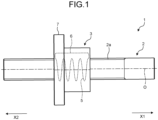
- FIG. 1 is an overall diagram of a ball screw device according to an embodiment.
- FIG. 2 is a cross-sectional view illustrating an arrangement state of a ball of the ball screw device of the embodiment.
- FIG. 3 is an explanatory diagram illustrating each step included in a method of manufacturing the ball screw device of the embodiment.
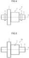
- FIG. 4 is an overall diagram of a nut unit manufactured in a nut unit preparation step of the embodiment.
- FIG. 5 is an overall diagram of a nut unit manufactured in a nut unit preparation step according to a first modification.
- FIG. 6 is an overall diagram of a screw shaft prepared in a screw shaft preparation step according to the embodiment.
- FIG. 7 is an overall diagram of a screw shaft prepared in a screw shaft preparation step according to a first modification.
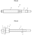
- FIG. 8 is an overall diagram of a screw shaft prepared in a screw shaft preparation step according to a second modification.
- FIG. 9 is a diagram illustrating a state in which a screw shaft is inserted into a nut in an assembly
- a ball screw device 1 includes a screw shaft 2, a nut 3, and a plurality of balls 4 (see FIG. 2 ).
- the screw shaft 2 is a shaft member, and has a spiral outer peripheral track surface 2a on an outer peripheral surface (see FIG. 6 ).
- a direction parallel to a central axis O of the screw shaft 2 is referred to as an axial direction.
- the outer peripheral track surface 2a is provided not on the entirety of the screw shaft 2 in the axial direction, but only on a part of the screw shaft.
- the nut 3 is a cylindrical component, and has a spiral inner peripheral track surface 3a on an inner peripheral surface.
- the outer peripheral track surface 2a and the inner peripheral track surface 3a are the same lead and face each other. Therefore, a spiral track 5 is provided between the outer peripheral track surface 2a and the inner peripheral track surface 3a.
- the nut 3 includes a return path 6 extending in the axial direction. Furthermore, the nut 3 includes two deflectors (not illustrated). The deflectors scoop up the balls 4 from a terminal end of the track 5 and guide the balls 4 to the return path 6, and supply the balls from the return path 6 to a starting end of the track 5.
- the deflectors are exemplified as an example of a circulation component. However, other than the deflectors, a tube, a top, an end cap, and other circulation systems may be used, and there is no particular limitation.
- a flange 7 for fixing the nut 3 to another component is provided at one end portion in the axial direction on the outer peripheral surface of the nut 3.
- a flanged nut is cited as an example of the nut, but the present disclosure may be other nuts such as a non-flanged nut, a square nut, and a trunnion nut, and is not particularly limited.
- a direction in which the flange 7 is disposed as viewed from a central portion of the nut 3 in the axial direction is referred to as a first direction X1, and a direction opposite to the first direction is referred to as a second direction X2.
- FIG. 2 illustrates a cross section of the track 5.
- the balls 4 are spherical rolling bodies. Each of the balls 4 is disposed on the track 5 between the outer peripheral track surface 2a and the inner peripheral track surface 3a.
- an axial gap is 0.05 mm or less. Note that the axial gap is a distance by which one of the screw shaft 2 and the nut 3 is fixed and the other of the screw shaft 2 and the nut 3 is movable in the axial direction without rotating. That is, the axial gap is a gap amount obtained by adding a gap d1 between a rolling surface of the ball 4 and the inner peripheral track surface 3a and a gap d2 between the rolling surface of the ball 4 and the outer peripheral track surface 2a.
- the axial gap also includes a state in which the track surface (2a, 3a) and the ball 4 are in contact with each other and a preload is applied (a state in which the gap amount is negative), in addition to the case where there is a gap between the track surface (2a, 3a) and the ball 4.
- the method of manufacturing the ball screw device 1 includes a nut unit preparation step S1, a screw shaft preparation step S2, and an assembly step S3.
- the assembly step S3 is performed after the nut unit preparation step S1 and the screw shaft preparation step S2.
- either step may be performed first, or both steps may be performed simultaneously.
- the nut unit preparation step S1 is a step of preparing a nut unit 10. As illustrated in FIG. 4 , the nut unit 10 is formed by assembling and integrating the nut 3, the ball 4 (not illustrated), the circulation component (not illustrated), and a temporary shaft 11. In the nut unit preparation step S1 of the present embodiment, first, the nut 3, the ball 4 (not illustrated), the circulation component (not illustrated), and the temporary shaft 11 are prepared. Note that the temporary shaft 11 is a cylindrical component.
- a reference value of a state in which the ball 4 is inserted into the track surface 3a of the nut 3 is set in advance, and it has been confirmed by inspection that a manufacturing error (variation) of the nut and the ball is within a predetermined control range.
- the control range with respect to the predetermined reference value is controlled within a range stricter than the tolerance, in other words, the reference value is set in advance as a constant, and an allowable range is controlled within a range narrower than the tolerance.
- a method of measuring a ball center diameter (BCD) and determining the BCD together with a diameter of the inserted ball can be cited to confirm whether or not it is within the range of control with respect to the predetermined reference value.
- a master screw shaft serving as a master is assembled to a nut and a ball, the nut is fixed, and a moving distance (axial gap) in the axial direction is measured without the master screw shaft rotating.
- the nut unit 10 is assembled next.
- a circulation component is assembled to the nut 3.
- the temporary shaft 11 is inserted into the nut 3.
- the inner peripheral track surface 3a of the nut 3 faces the outer peripheral surface of the temporary shaft 11.
- the temporary shaft 11 is inserted into such an extent as not to cover a part of the inner peripheral track surface 3a, and a portion to be filled with the ball 4 is left open.
- the ball 4 is inserted between the inner peripheral track surface 3a of the nut 3 and the outer peripheral surface of the temporary shaft 11, and the inner peripheral track surface 3a and the return path are filled with the ball 4.
- the temporary shaft 11 is further pushed, and the temporary shaft 11 penetrates the nut 3. According to this, the ball 4 abuts on the outer peripheral surface of the temporary shaft 11, and the ball filled in the nut does not fall off from the inner peripheral track surface.
- the completed nut unit 10 is conveyed from a site 100 on which the nut unit preparation step S1 is performed to a site 102 on which the assembly step S3 is performed, and this step ends.
- the nut unit preparation step S1 of the present embodiment manufactures the nut unit 10 in the site 100
- the nut unit preparation step S1 of the present disclosure is not limited to the case of actually manufacturing the nut unit 10. That is, the nut unit preparation step S1 of the present disclosure includes a case where the nut unit 10 itself is purchased or imported from another country, and the nut unit 10 is carried into the site 100 and prepared.
- stoppers 12 are fitted to both end portions of the temporary shaft 11 at the time of assembling the nut unit 10.
- Each of the stoppers 12 is an annular component and is made of an elastic material.
- the stopper abuts on an end surface of the nut, and the temporary shaft is prevented from falling off from the nut.
- the nut unit 10 of the present embodiment may be packed with a bag-shaped packing material 13 as illustrated in FIG. 5 instead of the stopper 12. Note that, in the manufacturing method of the present disclosure, the stopper 12 and the packing material 13 are not essential, and the nut unit 10 may be conveyed as it is.
- the screw shaft preparation step S2 is a step of setting a reference value, which is a constant, in advance on the track surface 2a of the screw shaft 2, confirming whether or not the manufacturing error (variation) is within a predetermined control range, and preparing the screw shaft 2 satisfying a requirement of the control range.
- Whether or not the manufacturing error is within the control range with respect to a predetermined reference value can be determined by a method in which a master nut serving as a master is assembled to a screw shaft, the nut is fixed, and a moving distance (axial gap) of the master screw shaft in the axial direction is measured. Furthermore, there is a method of measuring a screw groove and making a determination by assuming a ball center diameter (BCD). Furthermore, the screw shaft 2 satisfying the predetermined control range is conveyed from a site 101 where the screw shaft preparation step S2 is performed to the site 102 where the assembly step S3 is performed, and this step ends.
- BCD ball center diameter
- the outer peripheral track surface 2a is provided in a part of the screw shaft 2 in the axial direction, but the present disclosure is not limited thereto.
- a screw shaft 2A may be provided with the entire outer peripheral track surface 2a in the axial direction.
- the screw shaft may be a screw shaft 2B including the outer peripheral track surface 2a, a fixing surface 2b for fixing the screw shaft 2B to another component, a male screw portion 2c, and all or a part of another machined portion.
- the fixing surface 2b is a surface to which a component that moves in the axial direction together with the screw shaft 2B is fitted.
- the screw shaft 2 prepared in the site 101 may be manufactured in the site 101.
- the screw shaft 2 may be a screw shaft carried into the site 101 from a place other than the site 101 by purchase (including import from another country), and is not particularly limited.
- the assembly step S3 is a step of assembling the ball screw device 1 by combining the nut unit 10 and the screw shaft 2 in the site 102.
- one nut unit 10 is arbitrarily picked up (selected) from a plurality of the nut units 10 manufactured with a predetermined reference value and a control range thereof, and the stopper 12 or the packing material 13 are removed.
- an end portion of one screw shaft 2 arbitrarily picked up (selected) from a plurality of the screw shafts 2 manufactured with a predetermined reference value and a control range thereof is inserted.
- the nut 3 is fixed, and the screw shaft 2 is rotated as indicated by an arrow A in FIG. 9 .
- the ball 4 filled in the nut 3 enters the outer peripheral track surface 2a of the screw shaft 2, and the screw shaft 2 gradually enters the nut 3.
- the temporary shaft 11 is pushed out by the screw shaft (see an arrow B in FIG. 9 ). Then, when the screw shaft 2 is rotated to such an extent that the screw shaft 2 penetrates the nut 3, the assembly of the ball screw device 1 is completed, and the assembly step S3 ends.
- the method of manufacturing the ball screw device of the embodiment includes the nut unit preparation step S1, the screw shaft preparation step S2, and the assembly step S3.
- the circulation component, the ball 4, and the temporary shaft 11 that prevents the ball 4 from falling off are assembled to the nut 3 provided with the inner peripheral track surface 3a to manufacture the nut unit 10.
- the screw shaft preparation step S2 the screw shaft 2 provided with the outer peripheral track surface 2a is prepared.
- the assembly step S3 after the nut unit preparation step S1 and the screw shaft preparation step S2, the temporary shaft 11 of an arbitrary nut unit 10 manufactured with a predetermined reference value and its control range is replaced with an arbitrary screw shaft 2 manufactured with a predetermined reference value and its control range, thereby manufacturing the ball screw device 1.
- the manufacturing method of the embodiment it is controlled whether or not the ball center diameters of the track surface 2a of the screw shaft 2 and the track surface of the nut unit 10 are within the control range from the set value according to the predetermined standard, and the assembled ball screw device 1 is also assembled by picking up the screw shaft 2 and the nut unit 10 having the same set value, so that the axial gap according to the standard is satisfied. Furthermore, in a case where the assembled screw shaft 2 or nut unit 10 is damaged, even if the screw shaft 2 or nut unit is replaced with a new screw shaft 2 or nut unit of the same standard, the axial gap of a predetermined standard is satisfied, and reassembly is facilitated.
- the ball 4 is assembled to the nut unit 10 in advance, it is possible to eliminate time and effort of adjusting the ball diameter satisfying the standard in the assembly step. Furthermore, in the assembly step, the screw shaft 2 and the nut unit 10 of the same standard can be arbitrarily assembled, and time and effort of selecting and adjusting the combination of the screw shaft 2 and the nut unit 10 can also be eliminated. Moreover, automation of the assembly can be easily realized.
- the stoppers 12 for preventing the temporary shaft 11 from falling off from the nut 3 are attached to both end portions of the temporary shaft 11.
- the nut unit preparation step S1 the nut unit is covered with the packing material 13 in order to prevent the temporary shaft 11 from falling off from the nut 3.
- the ball screw device of the present disclosure is not limited to one having the axial gap of 0.05 mm or less. Therefore, the axial gap may exceed 0.05 mm.
- the ball screw device of the present disclosure may be a ball screw device in which the standard of the axial gap is 0.05 mm or less, 0.02 mm or less, or 0.005 mm or less, or a preload is applied (the axial gap is 0 mm or less), and can be applied according to the grade of the ball screw device.
- the sites 100, 101, and 102 where each step is performed may refer to different places in the same factory, or may refer to separate factories far from each other, and are not particularly limited.
- the site 102 is not necessarily limited to a site owned by a manufacturing side, and may be on a site of an agent, a processing site, a user, or another side.
- the nut unit preparation step S1, the screw shaft preparation step S2, and the assembly step S3 may be the same site. That is, the nut unit preparation step S1 and the screw shaft preparation step S2 may be performed on the site 102 where the assembly step S3 is performed.
- the nut unit preparation step S1 the nut unit 10 manufactured in a country A may be imported and carried into the site 102 where the assembly step S3 is performed to prepare the nut unit 10.
- the screw shaft preparation step S2 the screw shaft 2 manufactured in a country B may be imported and carried into the site 102 where the assembly step S3 is performed to prepare the screw shaft 2.
Landscapes
- Engineering & Computer Science (AREA)
- General Engineering & Computer Science (AREA)
- Mechanical Engineering (AREA)
- Transmission Devices (AREA)
- Automatic Assembly (AREA)
Abstract
Description
- The present invention relates to a method of manufacturing a ball screw device.
- A ball screw device is a device that converts a rotational motion into a linear motion or a linear motion into a rotational motion. As described in the following Patent Literature, a ball screw device includes a screw shaft, a nut penetrating the screw shaft, and a plurality of balls disposed between the screw shaft and the nut. Furthermore, the ball screw device has been shipped as a ball screw device after confirming that an axial gap and a preload defined in the standard are satisfied.
- Patent Literature 1:
JP 2015-232346 A - Incidentally, manufacturing errors (variations) occur in the manufactured screw shaft and nut. Conventionally, in order to satisfy a predetermined gap or preload set for each product, adjustment is performed by stacking dimensions of three elements of a screw shaft, a nut, and a ball. In general, in a manufacturing process of a ball screw device, a screw shaft and a nut having a large manufacturing error are picked up, a ball diameter satisfying a standard axial gap or the like is selected, and a ball is filled in a track. That is, in the conventional manufacturing method, a ball screw device having a standard gap or preload is manufactured by combining a screw shaft and a nut, a ball selected, and these three elements as one set. Furthermore, in a case where one of the screw shaft and the nut of the ball screw device is damaged during the operation of the ball screw device and replaced with a new part instead of the damaged part (hereafter, reassembly), it is necessary to reselect the ball again in order to satisfy the axial gap or preload of the original standard. Therefore, assembling and reassembling of the ball screw device require a large amount of labor.
- The present disclosure has been made in view of the above problems, and an object thereof is to provide a method of manufacturing a ball screw device capable of reducing labor during assembly and reassembly.
- To achieve the above object, a method of manufacturing a ball screw device according to an embodiment is disclosed. The method includes a nut unit preparation step of preparing a nut unit in which a circulation component, a ball, and a temporary shaft that prevents the ball from falling off are assembled to a nut provided with an inner peripheral track surface, a screw shaft preparation step of preparing a screw shaft provided with an outer peripheral track surface, and an assembly step of replacing the temporary shaft of any of the nut units with any of the screw shafts to manufacture a ball screw device after the nut unit preparation step and the screw shaft preparation step.
- The ball is assembled to the nut unit in advance. Therefore, it is possible to eliminate time and effort to select the ball having a diameter satisfying the standard in the assembly step. Furthermore, if a tolerance of a reference value of the track surface of the screw shaft and a tolerance of a reference value of a contact position of the nut unit with the track surface of the screw shaft are strictly managed, even if the ball screw device is assembled with the screw shaft and the nut unit arbitrarily selected (picked up) from a plurality of the screw shafts and the nut units, the assembled screw shaft device satisfies an axial gap according to the standard. Furthermore, even if the assembled screw shaft is damaged or replaced with a new screw shaft or nut unit, the axial gap of the standard is satisfied. Therefore, reassembly is facilitated.
- As a desirable embodiment of the method of manufacturing a ball screw device, in the nut unit preparation step, a stopper that prevents the temporary shaft from falling off from the nut is attached to both end portions of the temporary shaft, or in the nut unit preparation step, in order to prevent the temporary shaft from falling off from the nut, the nut unit is covered with a packing material.
- According to the above configuration, it is possible to prevent the temporary shaft from falling off in a process of conveying the nut unit.
- In the method of manufacturing a ball screw device, in the ball screw device, an axial gap between the screw shaft and the nut unit is 0.05 mm or less. Or, in the ball screw device, an axial gap between the screw shaft and the nut unit is 0.02 mm or less. Or, in the ball screw device, an axial gap between the screw shaft and the nut unit is 0.005 mm or less. Or, in the ball screw device, an axial gap between the screw shaft and the nut unit is 0 mm or less.
- According to the method of manufacturing the ball screw device of the present disclosure, it is possible to reduce labor during assembly and reassembly. Furthermore, since the screw shaft and the nut unit can be arbitrarily combined, the screw shaft and the nut unit can be easily assembled regardless of a place, timing, and a worker. Moreover, since no adjustment is required, assembly on an automatic production line can be easily realized.
-
-
FIG. 1 is an overall diagram of a ball screw device according to an embodiment. -
FIG. 2 is a cross-sectional view illustrating an arrangement state of a ball of the ball screw device of the embodiment. -
FIG. 3 is an explanatory diagram illustrating each step included in the method of manufacturing the ball screw device of the embodiment. -
FIG. 4 is an overall diagram of a nut unit manufactured in a nut unit preparation step of the embodiment. -
FIG. 5 is an overall diagram of a nut unit manufactured in a nut unit preparation step according to a first modification. -
FIG. 6 is an overall diagram of a screw shaft prepared in a screw shaft preparation step according to the embodiment. -
FIG. 7 is an overall view of a screw shaft prepared in a screw shaft preparation step according to a first modification. -
FIG. 8 is an overall diagram of a screw shaft prepared in a screw shaft preparation step according to a second modification. -
FIG. 9 is a diagram illustrating a state in which a screw shaft is inserted into a nut in an assembly step. Description of Embodiments - Hereinafter, the present invention will be described in detail with reference to the drawings. Note that the present invention is not limited by a mode for carrying out the following invention (hereinafter, referred to as an embodiment). Furthermore, constituent elements in the following embodiments include those that can be easily assumed by those skilled in the art, those that are substantially the same, and those within a so-called equivalent range. Moreover, the constitution elements disclosed in the following embodiments can be appropriately combined.
-
FIG. 1 is an overall diagram of a ball screw device according to an embodiment.FIG. 2 is a cross-sectional view illustrating an arrangement state of a ball of the ball screw device of the embodiment.FIG. 3 is an explanatory diagram illustrating each step included in a method of manufacturing the ball screw device of the embodiment.FIG. 4 is an overall diagram of a nut unit manufactured in a nut unit preparation step of the embodiment.FIG. 5 is an overall diagram of a nut unit manufactured in a nut unit preparation step according to a first modification.FIG. 6 is an overall diagram of a screw shaft prepared in a screw shaft preparation step according to the embodiment.FIG. 7 is an overall diagram of a screw shaft prepared in a screw shaft preparation step according to a first modification.FIG. 8 is an overall diagram of a screw shaft prepared in a screw shaft preparation step according to a second modification.FIG. 9 is a diagram illustrating a state in which a screw shaft is inserted into a nut in an assembly step. - As illustrated in
FIG. 1 , aball screw device 1 includes ascrew shaft 2, anut 3, and a plurality of balls 4 (seeFIG. 2 ). Thescrew shaft 2 is a shaft member, and has a spiral outerperipheral track surface 2a on an outer peripheral surface (seeFIG. 6 ). In the following description, a direction parallel to a central axis O of thescrew shaft 2 is referred to as an axial direction. The outerperipheral track surface 2a is provided not on the entirety of thescrew shaft 2 in the axial direction, but only on a part of the screw shaft. - The
nut 3 is a cylindrical component, and has a spiral innerperipheral track surface 3a on an inner peripheral surface. The outerperipheral track surface 2a and the innerperipheral track surface 3a are the same lead and face each other. Therefore, aspiral track 5 is provided between the outerperipheral track surface 2a and the innerperipheral track surface 3a. - The
nut 3 includes areturn path 6 extending in the axial direction. Furthermore, thenut 3 includes two deflectors (not illustrated). The deflectors scoop up theballs 4 from a terminal end of thetrack 5 and guide theballs 4 to thereturn path 6, and supply the balls from thereturn path 6 to a starting end of thetrack 5. Note that, in the ball screw device of the present disclosure, the deflectors are exemplified as an example of a circulation component. However, other than the deflectors, a tube, a top, an end cap, and other circulation systems may be used, and there is no particular limitation. - A
flange 7 for fixing thenut 3 to another component is provided at one end portion in the axial direction on the outer peripheral surface of thenut 3. In the embodiment, a flanged nut is cited as an example of the nut, but the present disclosure may be other nuts such as a non-flanged nut, a square nut, and a trunnion nut, and is not particularly limited. Hereinafter, a direction in which theflange 7 is disposed as viewed from a central portion of thenut 3 in the axial direction is referred to as a first direction X1, and a direction opposite to the first direction is referred to as a second direction X2. -
FIG. 2 illustrates a cross section of thetrack 5. Theballs 4 are spherical rolling bodies. Each of theballs 4 is disposed on thetrack 5 between the outerperipheral track surface 2a and the innerperipheral track surface 3a. In the present embodiment, an axial gap is 0.05 mm or less. Note that the axial gap is a distance by which one of thescrew shaft 2 and thenut 3 is fixed and the other of thescrew shaft 2 and thenut 3 is movable in the axial direction without rotating. That is, the axial gap is a gap amount obtained by adding a gap d1 between a rolling surface of theball 4 and the innerperipheral track surface 3a and a gap d2 between the rolling surface of theball 4 and the outerperipheral track surface 2a. Furthermore, the axial gap also includes a state in which the track surface (2a, 3a) and theball 4 are in contact with each other and a preload is applied (a state in which the gap amount is negative), in addition to the case where there is a gap between the track surface (2a, 3a) and theball 4. - As illustrated in
FIG. 3 , the method of manufacturing theball screw device 1 includes a nut unit preparation step S1, a screw shaft preparation step S2, and an assembly step S3. The assembly step S3 is performed after the nut unit preparation step S1 and the screw shaft preparation step S2. Furthermore, in the order of the nut unit preparation step S1 and the screw shaft preparation step S2, either step may be performed first, or both steps may be performed simultaneously. - The nut unit preparation step S1 is a step of preparing a
nut unit 10. As illustrated inFIG. 4 , thenut unit 10 is formed by assembling and integrating thenut 3, the ball 4 (not illustrated), the circulation component (not illustrated), and atemporary shaft 11. In the nut unit preparation step S1 of the present embodiment, first, thenut 3, the ball 4 (not illustrated), the circulation component (not illustrated), and thetemporary shaft 11 are prepared. Note that thetemporary shaft 11 is a cylindrical component. - In the nut unit preparation step S1, with respect to the
nut 3 and theball 4 to be prepared, a reference value of a state in which theball 4 is inserted into thetrack surface 3a of thenut 3 is set in advance, and it has been confirmed by inspection that a manufacturing error (variation) of the nut and the ball is within a predetermined control range. Here, the control range with respect to the predetermined reference value is controlled within a range stricter than the tolerance, in other words, the reference value is set in advance as a constant, and an allowable range is controlled within a range narrower than the tolerance. As a result, the axial gap in the standard set by theball screw device 1 which is a finished product is satisfied. Furthermore, for example, a method of measuring a ball center diameter (BCD) and determining the BCD together with a diameter of the inserted ball can be cited to confirm whether or not it is within the range of control with respect to the predetermined reference value. Alternatively, there is a method in which a master screw shaft serving as a master is assembled to a nut and a ball, the nut is fixed, and a moving distance (axial gap) in the axial direction is measured without the master screw shaft rotating. - In the nut unit preparation step S1, after preparing each component, the
nut unit 10 is assembled next. To assemble thenut unit 10, a circulation component is assembled to thenut 3. Next, thetemporary shaft 11 is inserted into thenut 3. As a result, the innerperipheral track surface 3a of thenut 3 faces the outer peripheral surface of thetemporary shaft 11. Furthermore, thetemporary shaft 11 is inserted into such an extent as not to cover a part of the innerperipheral track surface 3a, and a portion to be filled with theball 4 is left open. Next, theball 4 is inserted between the innerperipheral track surface 3a of thenut 3 and the outer peripheral surface of thetemporary shaft 11, and the innerperipheral track surface 3a and the return path are filled with theball 4. Next, thetemporary shaft 11 is further pushed, and thetemporary shaft 11 penetrates thenut 3. According to this, theball 4 abuts on the outer peripheral surface of thetemporary shaft 11, and the ball filled in the nut does not fall off from the inner peripheral track surface. Then, the completednut unit 10 is conveyed from asite 100 on which the nut unit preparation step S1 is performed to asite 102 on which the assembly step S3 is performed, and this step ends. Note that, although the nut unit preparation step S1 of the present embodiment manufactures thenut unit 10 in thesite 100, the nut unit preparation step S1 of the present disclosure is not limited to the case of actually manufacturing thenut unit 10. That is, the nut unit preparation step S1 of the present disclosure includes a case where thenut unit 10 itself is purchased or imported from another country, and thenut unit 10 is carried into thesite 100 and prepared. - Note that, in the present embodiment,
stoppers 12 are fitted to both end portions of thetemporary shaft 11 at the time of assembling thenut unit 10. Each of thestoppers 12 is an annular component and is made of an elastic material. As a result, even if thetemporary shaft 11 moves in the axial direction during the conveyance of thenut unit 10, the stopper abuts on an end surface of the nut, and the temporary shaft is prevented from falling off from the nut. Furthermore, thenut unit 10 of the present embodiment may be packed with a bag-shapedpacking material 13 as illustrated inFIG. 5 instead of thestopper 12. Note that, in the manufacturing method of the present disclosure, thestopper 12 and the packingmaterial 13 are not essential, and thenut unit 10 may be conveyed as it is. - The screw shaft preparation step S2 is a step of setting a reference value, which is a constant, in advance on the
track surface 2a of thescrew shaft 2, confirming whether or not the manufacturing error (variation) is within a predetermined control range, and preparing thescrew shaft 2 satisfying a requirement of the control range. Whether or not the manufacturing error is within the control range with respect to a predetermined reference value can be determined by a method in which a master nut serving as a master is assembled to a screw shaft, the nut is fixed, and a moving distance (axial gap) of the master screw shaft in the axial direction is measured. Furthermore, there is a method of measuring a screw groove and making a determination by assuming a ball center diameter (BCD). Furthermore, thescrew shaft 2 satisfying the predetermined control range is conveyed from asite 101 where the screw shaft preparation step S2 is performed to thesite 102 where the assembly step S3 is performed, and this step ends. - Note that, in the
screw shaft 2 described in the embodiment, as illustrated inFIG. 6 , the outerperipheral track surface 2a is provided in a part of thescrew shaft 2 in the axial direction, but the present disclosure is not limited thereto. For example, as illustrated inFIG. 7 , ascrew shaft 2A may be provided with the entire outerperipheral track surface 2a in the axial direction. Alternatively, as illustrated inFIG. 8 , the screw shaft may be ascrew shaft 2B including the outerperipheral track surface 2a, a fixingsurface 2b for fixing thescrew shaft 2B to another component, amale screw portion 2c, and all or a part of another machined portion. Note that, the fixingsurface 2b is a surface to which a component that moves in the axial direction together with thescrew shaft 2B is fitted. Then, a nut screwed to themale screw portion 2c prevents a component fitted to the fixingsurface 2b from falling off. Furthermore, in the screw shaft preparation step S2 of the present disclosure, thescrew shaft 2 prepared in thesite 101 may be manufactured in thesite 101. Alternatively, thescrew shaft 2 may be a screw shaft carried into thesite 101 from a place other than thesite 101 by purchase (including import from another country), and is not particularly limited. - The assembly step S3 is a step of assembling the
ball screw device 1 by combining thenut unit 10 and thescrew shaft 2 in thesite 102. In the combination method, as illustrated inFIG. 9 , onenut unit 10 is arbitrarily picked up (selected) from a plurality of thenut units 10 manufactured with a predetermined reference value and a control range thereof, and thestopper 12 or the packingmaterial 13 are removed. Similarly, an end portion of onescrew shaft 2 arbitrarily picked up (selected) from a plurality of thescrew shafts 2 manufactured with a predetermined reference value and a control range thereof is inserted. Then, thenut 3 is fixed, and thescrew shaft 2 is rotated as indicated by an arrow A inFIG. 9 . As a result, theball 4 filled in thenut 3 enters the outerperipheral track surface 2a of thescrew shaft 2, and thescrew shaft 2 gradually enters thenut 3. As a result, thetemporary shaft 11 is pushed out by the screw shaft (see an arrow B inFIG. 9 ). Then, when thescrew shaft 2 is rotated to such an extent that thescrew shaft 2 penetrates thenut 3, the assembly of theball screw device 1 is completed, and the assembly step S3 ends. - As described above, the method of manufacturing the ball screw device of the embodiment includes the nut unit preparation step S1, the screw shaft preparation step S2, and the assembly step S3. In the nut unit preparation step S1, the circulation component, the
ball 4, and thetemporary shaft 11 that prevents theball 4 from falling off are assembled to thenut 3 provided with the innerperipheral track surface 3a to manufacture thenut unit 10. In the screw shaft preparation step S2, thescrew shaft 2 provided with the outerperipheral track surface 2a is prepared. In the assembly step S3, after the nut unit preparation step S1 and the screw shaft preparation step S2, thetemporary shaft 11 of anarbitrary nut unit 10 manufactured with a predetermined reference value and its control range is replaced with anarbitrary screw shaft 2 manufactured with a predetermined reference value and its control range, thereby manufacturing theball screw device 1. - According to the manufacturing method of the embodiment, it is controlled whether or not the ball center diameters of the
track surface 2a of thescrew shaft 2 and the track surface of thenut unit 10 are within the control range from the set value according to the predetermined standard, and the assembledball screw device 1 is also assembled by picking up thescrew shaft 2 and thenut unit 10 having the same set value, so that the axial gap according to the standard is satisfied. Furthermore, in a case where the assembledscrew shaft 2 ornut unit 10 is damaged, even if thescrew shaft 2 or nut unit is replaced with anew screw shaft 2 or nut unit of the same standard, the axial gap of a predetermined standard is satisfied, and reassembly is facilitated. Furthermore, since theball 4 is assembled to thenut unit 10 in advance, it is possible to eliminate time and effort of adjusting the ball diameter satisfying the standard in the assembly step. Furthermore, in the assembly step, thescrew shaft 2 and thenut unit 10 of the same standard can be arbitrarily assembled, and time and effort of selecting and adjusting the combination of thescrew shaft 2 and thenut unit 10 can also be eliminated. Moreover, automation of the assembly can be easily realized. - Furthermore, in the nut unit preparation step S1 of the embodiment, the
stoppers 12 for preventing thetemporary shaft 11 from falling off from thenut 3 are attached to both end portions of thetemporary shaft 11. Alternatively, as in a first modification, in the nut unit preparation step S1, the nut unit is covered with the packingmaterial 13 in order to prevent thetemporary shaft 11 from falling off from thenut 3. - Accordingly, when the
nut unit 10 is conveyed from thesite 100 to thesite 102, thetemporary shaft 11 is prevented from falling off. - Although the embodiment has been described above, the axial gap is 0.05 mm or less for the standard setting of the
ball screw device 1 manufactured in the embodiment, the ball screw device of the present disclosure is not limited to one having the axial gap of 0.05 mm or less. Therefore, the axial gap may exceed 0.05 mm. On the other hand, in consideration of the practicality of the precision grade ball screw, the ball screw device of the present disclosure may be a ball screw device in which the standard of the axial gap is 0.05 mm or less, 0.02 mm or less, or 0.005 mm or less, or a preload is applied (the axial gap is 0 mm or less), and can be applied according to the grade of the ball screw device. - Furthermore, the
sites site 102 is not necessarily limited to a site owned by a manufacturing side, and may be on a site of an agent, a processing site, a user, or another side. Furthermore, in the present disclosure, the nut unit preparation step S1, the screw shaft preparation step S2, and the assembly step S3 may be the same site. That is, the nut unit preparation step S1 and the screw shaft preparation step S2 may be performed on thesite 102 where the assembly step S3 is performed. In other words, in the nut unit preparation step S1, thenut unit 10 manufactured in a country A may be imported and carried into thesite 102 where the assembly step S3 is performed to prepare thenut unit 10. Similarly, in the screw shaft preparation step S2, thescrew shaft 2 manufactured in a country B may be imported and carried into thesite 102 where the assembly step S3 is performed to prepare thescrew shaft 2. -
- 1
- BALL SCREW DEVICE
- 2, 2A, 2B
- SCREW SHAFT
- 2a
- OUTER PERIPHERAL TRACK SURFACE
- 3
- NUT
- 3a
- INNER PERIPHERAL TRACK SURFACE
- 4
- BALL
- 10
- NUT UNIT
- 11
- TEMPORARY SHAFT
- 12
- STOPPER
- 13
- PACKING MATERIAL
- 51
- NUT UNIT PREPARATION STEP
- S2
- SCREW SHAFT PREPARATION STEP
- S3
- ASSEMBLY STEP
Claims (7)
- A method of manufacturing a ball screw device, the method comprising:a nut unit preparation step of preparing a nut unit in which a circulation component, a ball, and a temporary shaft that prevents the ball from falling off are assembled to a nut provided with an inner peripheral track surface;a screw shaft preparation step of preparing a screw shaft provided with an outer peripheral track surface; andan assembly step of replacing the temporary shaft of any of the nut units with any of the screw shafts to manufacture a ball screw device after the nut unit preparation step and the screw shaft preparation step.
- The method of manufacturing a ball screw device according to claim 1, wherein
in the nut unit preparation step, a stopper that prevents the temporary shaft from falling off from the nut is attached to both end portions of the temporary shaft. - The method of manufacturing a ball screw device according to claim 1, wherein
in the nut unit preparation step, in order to prevent the temporary shaft from falling off from the nut, the nut unit is covered with a packing material. - The method of manufacturing a ball screw device according to any one of claims 1 to 3, wherein
in the ball screw device, an axial gap between the screw shaft and the nut unit is 0.05 mm or less. - The method of manufacturing a ball screw device according to any one of claims 1 to 3, wherein
in the ball screw device, an axial gap between the screw shaft and the nut unit is 0.02 mm or less. - The method of manufacturing a ball screw device according to any one of claims 1 to 3, wherein
in the ball screw device, an axial gap between the screw shaft and the nut unit is 0.005 mm or less. - The method of manufacturing a ball screw device according to any one of claims 1 to 3, wherein
in the ball screw device, an axial gap between the screw shaft and the nut unit is 0 mm or less.
Applications Claiming Priority (2)
| Application Number | Priority Date | Filing Date | Title |
|---|---|---|---|
| JP2021060201A JP2022156482A (en) | 2021-03-31 | 2021-03-31 | Manufacturing method of ball screw device |
| PCT/JP2022/004006 WO2022209260A1 (en) | 2021-03-31 | 2022-02-02 | Method for manufacturing ball screw device |
Publications (2)
| Publication Number | Publication Date |
|---|---|
| EP4316728A1 true EP4316728A1 (en) | 2024-02-07 |
| EP4316728A4 EP4316728A4 (en) | 2025-03-12 |
Family
ID=83458715
Family Applications (1)
| Application Number | Title | Priority Date | Filing Date |
|---|---|---|---|
| EP22779489.8A Withdrawn EP4316728A4 (en) | 2021-03-31 | 2022-02-02 | Method for manufacturing ball screw device |
Country Status (7)
| Country | Link |
|---|---|
| US (1) | US12269133B2 (en) |
| EP (1) | EP4316728A4 (en) |
| JP (1) | JP2022156482A (en) |
| KR (1) | KR20230169114A (en) |
| CN (1) | CN117203449A (en) |
| TW (1) | TW202246680A (en) |
| WO (1) | WO2022209260A1 (en) |
Family Cites Families (12)
| Publication number | Priority date | Publication date | Assignee | Title |
|---|---|---|---|---|
| WO1993009911A1 (en) * | 1991-11-15 | 1993-05-27 | Yotaro Hatamura | Feed screw device and precisely positioning micromotion feed system |
| JPH06288458A (en) * | 1993-03-31 | 1994-10-11 | Tsubakimoto Seiko:Kk | Ball screw with removable screw shaft, and reactor control rod driving device utilizing this ball screw |
| JP4042511B2 (en) | 2002-09-26 | 2008-02-06 | 日本精工株式会社 | Ball screw device assembly method and assembly device |
| JP2004257466A (en) * | 2003-02-26 | 2004-09-16 | Nsk Ltd | Ball screw |
| JP4222263B2 (en) | 2004-06-23 | 2009-02-12 | 日本精工株式会社 | Ball screw device assembling apparatus and ball screw device assembling method using the same |
| JP4812589B2 (en) * | 2006-10-19 | 2011-11-09 | Ntn株式会社 | Ball screw nut retaining device and method thereof |
| JP5102715B2 (en) * | 2008-07-30 | 2012-12-19 | Ntn株式会社 | Electric linear actuator and method for assembling the same |
| JP5531914B2 (en) | 2010-11-01 | 2014-06-25 | 日本精工株式会社 | Ball screw nut attaching / detaching jig and nut attaching / detaching method using the same |
| TWM425959U (en) * | 2011-12-07 | 2012-04-01 | Univ Nat Formosa | Nut structure of ball screw having micro fan |
| JP2015232346A (en) | 2014-06-09 | 2015-12-24 | 日本精工株式会社 | Ball screw and manufacturing method therefor |
| JP6699364B2 (en) | 2016-06-01 | 2020-05-27 | 株式会社ジェイテクト | Ball screw device manufacturing method and steering device manufacturing method using ball screw device |
| JP2019105296A (en) * | 2017-12-12 | 2019-06-27 | 株式会社ジェイテクト | Adjusting method of ball screw device and manufacturing method |
-
2021
- 2021-03-31 JP JP2021060201A patent/JP2022156482A/en active Pending
-
2022
- 2022-02-02 KR KR1020237033518A patent/KR20230169114A/en not_active Ceased
- 2022-02-02 US US18/285,118 patent/US12269133B2/en active Active
- 2022-02-02 CN CN202280025628.XA patent/CN117203449A/en active Pending
- 2022-02-02 WO PCT/JP2022/004006 patent/WO2022209260A1/en not_active Ceased
- 2022-02-02 EP EP22779489.8A patent/EP4316728A4/en not_active Withdrawn
- 2022-03-24 TW TW111111097A patent/TW202246680A/en unknown
Also Published As
| Publication number | Publication date |
|---|---|
| CN117203449A (en) | 2023-12-08 |
| JP2022156482A (en) | 2022-10-14 |
| WO2022209260A1 (en) | 2022-10-06 |
| TW202246680A (en) | 2022-12-01 |
| US20240165753A1 (en) | 2024-05-23 |
| US12269133B2 (en) | 2025-04-08 |
| KR20230169114A (en) | 2023-12-15 |
| EP4316728A4 (en) | 2025-03-12 |
Similar Documents
| Publication | Publication Date | Title |
|---|---|---|
| US10760664B2 (en) | Method of producing wave gear device and wave gear device | |
| US11209078B2 (en) | Transmission gear and deceleration mechanism comprising the same | |
| GB2320066A (en) | Method for measuring a double-row rolling bearing preload | |
| US20010034931A1 (en) | Roller turret including rollers mounted on support portions of roller shafts, which are eccentric with respect to stud portions fixed in holes in turret body, and method of manufacturing the roller turret | |
| US9685842B2 (en) | Direct drive motor, conveyance device, inspection device, and machine tool | |
| US20240165753A1 (en) | Method of manufacturing ball screw device | |
| US5033873A (en) | Rotary bearing assembly having an insertion hole | |
| EP2985113B1 (en) | Production facility | |
| CN106321648B (en) | Bearing and speed reducer | |
| EP1978270B1 (en) | Method for manufacturing hub unit and hub unit | |
| US6811117B2 (en) | Process for assembly of landing gear on an aircraft structure and aircraft comprising such landing gear | |
| US8807841B2 (en) | Bearing assembly | |
| US5438888A (en) | Device for compensating pitch errors in worm gears | |
| CN107444472A (en) | The manufacture method of ball-screw apparatus and used ball-screw apparatus transfer manufacture method | |
| EP4130501B1 (en) | Roller sequencing for improved bearing runout | |
| EP0426279A2 (en) | Hollow roller bearing and method of making and mounting same | |
| EP3203099B1 (en) | Ball bearing cage | |
| US20130155823A1 (en) | Smooth timepiece bearing | |
| CN113118870B (en) | Quality detection method, system, equipment and storage medium based on intelligent processing station | |
| CN110206428A (en) | A kind of non-co-planar hinge of shaft and the robot with the hinge | |
| US9683608B2 (en) | Universal joint bearing, joint cross, universal joint, and multi-row needle roller bearing | |
| US10197467B2 (en) | Modular calibration rotor for a horizontal balancer | |
| KR20180065873A (en) | Separable double row angular ball bearing, outer race assembly and inner race assembly | |
| US20240183400A1 (en) | Multi-row bearing and bearing unit | |
| CN223868416U (en) | Crossed roller bearing |
Legal Events
| Date | Code | Title | Description |
|---|---|---|---|
| STAA | Information on the status of an ep patent application or granted ep patent |
Free format text: STATUS: THE INTERNATIONAL PUBLICATION HAS BEEN MADE |
|
| PUAI | Public reference made under article 153(3) epc to a published international application that has entered the european phase |
Free format text: ORIGINAL CODE: 0009012 |
|
| STAA | Information on the status of an ep patent application or granted ep patent |
Free format text: STATUS: REQUEST FOR EXAMINATION WAS MADE |
|
| 17P | Request for examination filed |
Effective date: 20230928 |
|
| AK | Designated contracting states |
Kind code of ref document: A1 Designated state(s): AL AT BE BG CH CY CZ DE DK EE ES FI FR GB GR HR HU IE IS IT LI LT LU LV MC MK MT NL NO PL PT RO RS SE SI SK SM TR |
|
| DAV | Request for validation of the european patent (deleted) | ||
| DAX | Request for extension of the european patent (deleted) | ||
| A4 | Supplementary search report drawn up and despatched |
Effective date: 20250207 |
|
| RIC1 | Information provided on ipc code assigned before grant |
Ipc: F16H 25/22 20060101ALI20250203BHEP Ipc: B23P 21/00 20060101AFI20250203BHEP |
|
| STAA | Information on the status of an ep patent application or granted ep patent |
Free format text: STATUS: THE APPLICATION IS DEEMED TO BE WITHDRAWN |
|
| 18D | Application deemed to be withdrawn |
Effective date: 20250826 |