EP4316713A1 - Processing tool - Google Patents
Processing tool Download PDFInfo
- Publication number
- EP4316713A1 EP4316713A1 EP23749752.4A EP23749752A EP4316713A1 EP 4316713 A1 EP4316713 A1 EP 4316713A1 EP 23749752 A EP23749752 A EP 23749752A EP 4316713 A1 EP4316713 A1 EP 4316713A1
- Authority
- EP
- European Patent Office
- Prior art keywords
- drive shaft
- main drive
- shaft
- center
- head
- Prior art date
- Legal status (The legal status is an assumption and is not a legal conclusion. Google has not performed a legal analysis and makes no representation as to the accuracy of the status listed.)
- Granted
Links
Images


Classifications
-
- B—PERFORMING OPERATIONS; TRANSPORTING
- B23—MACHINE TOOLS; METAL-WORKING NOT OTHERWISE PROVIDED FOR
- B23Q—DETAILS, COMPONENTS, OR ACCESSORIES FOR MACHINE TOOLS, e.g. ARRANGEMENTS FOR COPYING OR CONTROLLING; MACHINE TOOLS IN GENERAL CHARACTERISED BY THE CONSTRUCTION OF PARTICULAR DETAILS OR COMPONENTS; COMBINATIONS OR ASSOCIATIONS OF METAL-WORKING MACHINES, NOT DIRECTED TO A PARTICULAR RESULT
- B23Q5/00—Driving or feeding mechanisms; Control arrangements therefor
- B23Q5/02—Driving main working members
- B23Q5/04—Driving main working members rotary shafts, e.g. working-spindles
- B23Q5/043—Accessories for spindle drives
- B23Q5/045—Angle drives
-
- B—PERFORMING OPERATIONS; TRANSPORTING
- B23—MACHINE TOOLS; METAL-WORKING NOT OTHERWISE PROVIDED FOR
- B23B—TURNING; BORING
- B23B31/00—Chucks; Expansion mandrels; Adaptations thereof for remote control
- B23B31/02—Chucks
- B23B31/08—Chucks holding tools yieldably
-
- B—PERFORMING OPERATIONS; TRANSPORTING
- B23—MACHINE TOOLS; METAL-WORKING NOT OTHERWISE PROVIDED FOR
- B23C—MILLING
- B23C3/00—Milling particular work; Special milling operations; Machines therefor
- B23C3/12—Trimming or finishing edges, e.g. deburring welded corners
-
- B—PERFORMING OPERATIONS; TRANSPORTING
- B24—GRINDING; POLISHING
- B24B—MACHINES, DEVICES, OR PROCESSES FOR GRINDING OR POLISHING; DRESSING OR CONDITIONING OF ABRADING SURFACES; FEEDING OF GRINDING, POLISHING, OR LAPPING AGENTS
- B24B9/00—Machines or devices designed for grinding edges or bevels on work or for removing burrs; Accessories therefor
-
- F—MECHANICAL ENGINEERING; LIGHTING; HEATING; WEAPONS; BLASTING
- F16—ENGINEERING ELEMENTS AND UNITS; GENERAL MEASURES FOR PRODUCING AND MAINTAINING EFFECTIVE FUNCTIONING OF MACHINES OR INSTALLATIONS; THERMAL INSULATION IN GENERAL
- F16C—SHAFTS; FLEXIBLE SHAFTS; ELEMENTS OR CRANKSHAFT MECHANISMS; ROTARY BODIES OTHER THAN GEARING ELEMENTS; BEARINGS
- F16C23/00—Bearings for exclusively rotary movement adjustable for aligning or positioning
- F16C23/02—Sliding-contact bearings
- F16C23/04—Sliding-contact bearings self-adjusting
- F16C23/043—Sliding-contact bearings self-adjusting with spherical surfaces, e.g. spherical plain bearings
- F16C23/045—Sliding-contact bearings self-adjusting with spherical surfaces, e.g. spherical plain bearings for radial load mainly, e.g. radial spherical plain bearings
-
- F—MECHANICAL ENGINEERING; LIGHTING; HEATING; WEAPONS; BLASTING
- F16—ENGINEERING ELEMENTS AND UNITS; GENERAL MEASURES FOR PRODUCING AND MAINTAINING EFFECTIVE FUNCTIONING OF MACHINES OR INSTALLATIONS; THERMAL INSULATION IN GENERAL
- F16C—SHAFTS; FLEXIBLE SHAFTS; ELEMENTS OR CRANKSHAFT MECHANISMS; ROTARY BODIES OTHER THAN GEARING ELEMENTS; BEARINGS
- F16C3/00—Shafts; Axles; Cranks; Eccentrics
- F16C3/02—Shafts; Axles
- F16C3/023—Shafts; Axles made of several parts, e.g. by welding
-
- B—PERFORMING OPERATIONS; TRANSPORTING
- B23—MACHINE TOOLS; METAL-WORKING NOT OTHERWISE PROVIDED FOR
- B23C—MILLING
- B23C2260/00—Details of constructional elements
- B23C2260/08—Bearings
-
- B—PERFORMING OPERATIONS; TRANSPORTING
- B23—MACHINE TOOLS; METAL-WORKING NOT OTHERWISE PROVIDED FOR
- B23Q—DETAILS, COMPONENTS, OR ACCESSORIES FOR MACHINE TOOLS, e.g. ARRANGEMENTS FOR COPYING OR CONTROLLING; MACHINE TOOLS IN GENERAL CHARACTERISED BY THE CONSTRUCTION OF PARTICULAR DETAILS OR COMPONENTS; COMBINATIONS OR ASSOCIATIONS OF METAL-WORKING MACHINES, NOT DIRECTED TO A PARTICULAR RESULT
- B23Q1/00—Members which are comprised in the general build-up of a form of machine, particularly relatively large fixed members
- B23Q1/25—Movable or adjustable work or tool supports
- B23Q1/26—Movable or adjustable work or tool supports characterised by constructional features relating to the co-operation of relatively movable members; Means for preventing relative movement of such members
- B23Q1/32—Relative movement obtained by co-operating spherical surfaces, e.g. ball-and-socket joints
-
- F—MECHANICAL ENGINEERING; LIGHTING; HEATING; WEAPONS; BLASTING
- F16—ENGINEERING ELEMENTS AND UNITS; GENERAL MEASURES FOR PRODUCING AND MAINTAINING EFFECTIVE FUNCTIONING OF MACHINES OR INSTALLATIONS; THERMAL INSULATION IN GENERAL
- F16C—SHAFTS; FLEXIBLE SHAFTS; ELEMENTS OR CRANKSHAFT MECHANISMS; ROTARY BODIES OTHER THAN GEARING ELEMENTS; BEARINGS
- F16C17/00—Sliding-contact bearings for exclusively rotary movement
- F16C17/02—Sliding-contact bearings for exclusively rotary movement for radial load only
-
- F—MECHANICAL ENGINEERING; LIGHTING; HEATING; WEAPONS; BLASTING
- F16—ENGINEERING ELEMENTS AND UNITS; GENERAL MEASURES FOR PRODUCING AND MAINTAINING EFFECTIVE FUNCTIONING OF MACHINES OR INSTALLATIONS; THERMAL INSULATION IN GENERAL
- F16C—SHAFTS; FLEXIBLE SHAFTS; ELEMENTS OR CRANKSHAFT MECHANISMS; ROTARY BODIES OTHER THAN GEARING ELEMENTS; BEARINGS
- F16C2322/00—Apparatus used in shaping articles
- F16C2322/39—General buildup of machine tools, e.g. spindles, slides, actuators
-
- F—MECHANICAL ENGINEERING; LIGHTING; HEATING; WEAPONS; BLASTING
- F16—ENGINEERING ELEMENTS AND UNITS; GENERAL MEASURES FOR PRODUCING AND MAINTAINING EFFECTIVE FUNCTIONING OF MACHINES OR INSTALLATIONS; THERMAL INSULATION IN GENERAL
- F16D—COUPLINGS FOR TRANSMITTING ROTATION; CLUTCHES; BRAKES
- F16D3/00—Yielding couplings, i.e. with means permitting movement between the connected parts during the drive
- F16D3/16—Universal joints in which flexibility is produced by means of pivots or sliding or rolling connecting parts
- F16D3/20—Universal joints in which flexibility is produced by means of pivots or sliding or rolling connecting parts one coupling part entering a sleeve of the other coupling part and connected thereto by sliding or rolling members
- F16D3/22—Universal joints in which flexibility is produced by means of pivots or sliding or rolling connecting parts one coupling part entering a sleeve of the other coupling part and connected thereto by sliding or rolling members the rolling members being balls, rollers, or the like, guided in grooves or sockets in both coupling parts
- F16D3/223—Universal joints in which flexibility is produced by means of pivots or sliding or rolling connecting parts one coupling part entering a sleeve of the other coupling part and connected thereto by sliding or rolling members the rolling members being balls, rollers, or the like, guided in grooves or sockets in both coupling parts the rolling members being guided in grooves in both coupling parts
-
- F—MECHANICAL ENGINEERING; LIGHTING; HEATING; WEAPONS; BLASTING
- F16—ENGINEERING ELEMENTS AND UNITS; GENERAL MEASURES FOR PRODUCING AND MAINTAINING EFFECTIVE FUNCTIONING OF MACHINES OR INSTALLATIONS; THERMAL INSULATION IN GENERAL
- F16D—COUPLINGS FOR TRANSMITTING ROTATION; CLUTCHES; BRAKES
- F16D3/00—Yielding couplings, i.e. with means permitting movement between the connected parts during the drive
- F16D3/16—Universal joints in which flexibility is produced by means of pivots or sliding or rolling connecting parts
- F16D3/24—Universal joints in which flexibility is produced by means of pivots or sliding or rolling connecting parts comprising balls, rollers, or the like between overlapping driving faces, e.g. cogs, on both coupling parts
Definitions
- the present invention relates to a machining tool, and more specifically, relates to a machining tool that is suitable as a holder for deburring tools by which the wear of sliding parts is significantly reduced.
- FIG. 5 Shown in FIG. 5 is the Second Embodiment of Patent Document 1, referred to as FIG. 9 in the Document.
- the machining tool shown in FIG. 5 is provided with a universal joint rod 3 inside the tool.
- FIG. 5 a case covering the outside of a spherical bearing is omitted.
- FIG. 6 is an internal structure diagram that shows a state in which a conventional main drive shaft 14 and holder 15 shown in FIG. 5 are tilted. Referring to FIG.
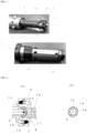
- FIGS. 7(a) and 7(b) are photographs showing a new article and a worn-out article of the conventional universal joint rod 3.
- pins 1, which are provided to protrude from the universal joint rod 3, have worn out due to friction with pin grooves 2.
- the tips of the pins 1 in FIG. 7(b) are significantly chipped away compared to the new pins 1 in FIG. 7(a) .
- Patent Document 1 Japanese Unexamined Patent Application Publication No. 2005-349549
- the present invention was made to address the problems, and the object of the present invention is to provide a machining tool that causes little wear at engaging parts between a main drive shaft and a driving shaft even if the main drive shaft is tilted.
- a machining tool includes an upper shaft (6) that is to be attached to a host device, through which torque is transmitted, a driving shaft (5) that is to be inserted into the upper shaft (6) to extend along the axis of the upper shaft (6), a main drive shaft (14) that is to be attached to a head of the driving shaft (5), a holder (15) that is to be inserted into a head of the main drive shaft (14), to which a cutting tool (9) is attached, a spherical bearing (4) that supports an outer side of the main drive shaft (14) so that the main drive shaft (14) is tiltable, a center steel ball (7) that is provided to be sandwiched between a depression in the center of the head of the drive shaft (5) and an opposite depression in the center of the rear end of the main drive shaft (14), and multiple axial steel balls (10) that are provided to long grooves (11) on the outer surface of the head of the drive shaft (5), and provided to holes (18) of the main drive shaft (14).
- the machining tool further includes a spring (12) that biases the driving shaft (5) in the axial direction, wherein the center (8) of the center steel ball (7) is positioned to be offset to the cutting tool (9) from the center (13) of the spherical bearing (4).
- the machining tool of the present invention includes a center steel ball to be sandwiched between a depression in the center of the head of a driving shaft and a depression in the center of the rear end of a main drive shaft, and multiple axial steel balls to be fitted to long grooves of the driving shaft and holes of a main drive shaft. Because the center steel ball and axial steel balls reduce friction occurring at engaging parts between the driving shaft and the main drive shaft even if the main drive shaft is tilted, the machining tool of the present invention can reduce the wear at the engaging parts.
- the machining tool of the present invention eliminates the use of a universal joint rod because the center steel ball and axial steel balls are provided to be fitted into the driving shaft and the main drive shaft. This configuration allows a holder along with the main drive shaft to be tilted at a predetermined angle with respect to the driving shaft.
- the transition of the main drive shaft from the tilted state to the unloaded state allows the central axis of the drive shaft to be aligned with that of the main drive shaft linearly.
- FIG. 1 is an internal structure diagram of a machining tool 100 according to the present invention.
- An upper shaft 6 is configured to be detachably attached to a host device such as a working machine or a robot, through which torque is transmitted.
- a drive shaft 5 is inserted into the upper shaft 6 to extend along the axis of the upper shaft 6.
- a main drive shaft 14 is attached to the head of the drive shaft 5 at the rear end thereof, and a holder 15 is attached to the head of the main drive shaft 14.
- a cutting tool 9 is attached to the head of the holder 15.
- a spherical bearing 4 is provided to support the outer side of the main drive shaft 14 so that the main drive shaft 14 is tiltable.
- a cover (not shown) is provided to envelop the portions from the upper shaft 6 to the spherical bearing 4.
- FIG. 2 is an internal structure diagram that shows a state in which the main drive shaft 14 and the holder 15 in FIG. 1 are tilted.
- the main drive shaft 14 and the holder 15 tilt up to approximately 5°.
- a depression is provided in the center of the head of the drive shaft 5 and in the center of the rear end of the main drive shaft 14.
- a center steel ball 7 is provided to be sandwiched between the depression of the drive shaft 5 and the opposite depression of the main drive shaft 14.
- Long grooves 11 are provided on the outer surface of the head of the drive shaft 5, and multiple holes 18 are provided on the main drive shaft 14.
- Multiple axial steel balls 10 are provided to be fitted to the long grooves 11 and the holes 18.
- FIG. 3 shows the drive shaft 5 and the main drive shaft 14, illustrating that the drive shaft 5 is to be inserted into the main drive shaft 14 as shown in FIG. 1 .
- the center steel ball 7 and the axial steel balls 10 are arranged at the head of the drive shaft 5, but this arrangement of the balls is an example for the sake of convenience.
- the center steel ball 7 is inserted into the position of the drive shaft 5 corresponding to the depression of the main drive shaft 14, and the axial steel balls 10 are inserted into the positions of the drive shaft 5 corresponding to the holes 18 of the main drive shaft 14.
- the drive shaft 5 is then inserted into the main drive shaft 14, which causes the center steel ball 7 to be housed in the depression in the center of the head of the drive shaft 5, and the axial steel balls 10 to be housed in the long grooves 11 of the drive shaft 5.
- FIG. 4(a) is an enlarged internal view of a spherical bearing where the main drive shaft 14 and the holder 15 shown in FIG. 1 are tilted
- FIG. 4(b) is a diagram showing the arrangement of the axial steel balls.
- the center steel ball 7 is provided to be sandwiched between the depression in the center of the head of the drive shaft 5 and the opposite depression in the center of the rear end of the main drive shaft 14.
- the axial steel balls 10 are provided to be fitted on the outer surface of the drive shaft 5 and in the holes 18 of the main drive shaft 14. Referring to FIG. 4(a) , a center 8 of the center steel ball 7 is positioned to be offset to the cutting tool 9 from a center 13 of the spherical bearing.
- axial steel balls 10 are provided such that six balls are arranged to be fitted on the outer surface of the drive shaft 5 and in the holes 18 of the main drive shaft 14.
- the number of the axial steel balls 10 can be three to ten without limiting to six.
- the present invention significantly reduces wear where friction occurs between the main drive shaft and the drive shaft, thereby extending the service life of a machining tool and making the tool more suitable for deburring.
Landscapes
- Engineering & Computer Science (AREA)
- Mechanical Engineering (AREA)
- General Engineering & Computer Science (AREA)
- Ocean & Marine Engineering (AREA)
- Milling Processes (AREA)
- Cutting Tools, Boring Holders, And Turrets (AREA)
- Milling, Broaching, Filing, Reaming, And Others (AREA)
- Machine Tool Units (AREA)
- Drilling And Boring (AREA)
Abstract
Description
- The present invention relates to a machining tool, and more specifically, relates to a machining tool that is suitable as a holder for deburring tools by which the wear of sliding parts is significantly reduced.
- The applicant of the present invention proposed a machining tool used for deburring in Patent Document 1 (
Japan Unexamined Patent Application Publication No. 2005-349549 FIG. 5 is the Second Embodiment ofPatent Document 1, referred to as FIG. 9 in the Document. The machining tool shown inFIG. 5 is provided with auniversal joint rod 3 inside the tool. InFIG. 5 , a case covering the outside of a spherical bearing is omitted.FIG. 6 is an internal structure diagram that shows a state in which a conventionalmain drive shaft 14 andholder 15 shown inFIG. 5 are tilted. Referring toFIG. 6 , the machining tool operates such that theuniversal joint rod 3 can tilt 3° upward to the right in the drawing, and themain drive shaft 14 and theholder 15 can tilt 5° downward to the right in the drawing.FIGS. 7(a) and 7(b) are photographs showing a new article and a worn-out article of the conventionaluniversal joint rod 3. Referring toFIG. 7(b) ,pins 1, which are provided to protrude from theuniversal joint rod 3, have worn out due to friction withpin grooves 2. The tips of thepins 1 inFIG. 7(b) are significantly chipped away compared to thenew pins 1 inFIG. 7(a) . Such wear causes the tilting action of the machining tool to be less smooth, and makes it impossible to transmit the driving force, which is the main function to be achieved by the machining tool. This necessitates earlier replacement of engaging parts, although the timing of replacement depends on the size of the load. - Patent Document 1:
Japanese Unexamined Patent Application Publication No. 2005-349549 - The present invention was made to address the problems, and the object of the present invention is to provide a machining tool that causes little wear at engaging parts between a main drive shaft and a driving shaft even if the main drive shaft is tilted.
- A machining tool is provided that includes an upper shaft (6) that is to be attached to a host device, through which torque is transmitted, a driving shaft (5) that is to be inserted into the upper shaft (6) to extend along the axis of the upper shaft (6), a main drive shaft (14) that is to be attached to a head of the driving shaft (5), a holder (15) that is to be inserted into a head of the main drive shaft (14), to which a cutting tool (9) is attached, a spherical bearing (4) that supports an outer side of the main drive shaft (14) so that the main drive shaft (14) is tiltable, a center steel ball (7) that is provided to be sandwiched between a depression in the center of the head of the drive shaft (5) and an opposite depression in the center of the rear end of the main drive shaft (14), and multiple axial steel balls (10) that are provided to long grooves (11) on the outer surface of the head of the drive shaft (5), and provided to holes (18) of the main drive shaft (14).
- The machining tool further includes a spring (12) that biases the driving shaft (5) in the axial direction, wherein the center (8) of the center steel ball (7) is positioned to be offset to the cutting tool (9) from the center (13) of the spherical bearing (4).
- The machining tool of the present invention includes a center steel ball to be sandwiched between a depression in the center of the head of a driving shaft and a depression in the center of the rear end of a main drive shaft, and multiple axial steel balls to be fitted to long grooves of the driving shaft and holes of a main drive shaft. Because the center steel ball and axial steel balls reduce friction occurring at engaging parts between the driving shaft and the main drive shaft even if the main drive shaft is tilted, the machining tool of the present invention can reduce the wear at the engaging parts. The machining tool of the present invention eliminates the use of a universal joint rod because the center steel ball and axial steel balls are provided to be fitted into the driving shaft and the main drive shaft. This configuration allows a holder along with the main drive shaft to be tilted at a predetermined angle with respect to the driving shaft.
- Because the center of the center steel ball is positioned to be offset to the cutting tool from the center of the spherical bearing, the transition of the main drive shaft from the tilted state to the unloaded state allows the central axis of the drive shaft to be aligned with that of the main drive shaft linearly. A spring presses the driving shaft, the center steel ball, and the main drive shaft, which allows the central axis of the driving shaft to be aligned with that of the main drive shaft linearly.
-
- FIG. 1
- is an internal structure diagram of a machining tool according to the present invention.
- FIG. 2
- is an internal structure diagram that shows a state in which a main drive shaft and a holder in
FIG. 1 are tilted. - FIG. 3
- shows a drive shaft and the main drive shaft, in which the drive shaft is to be inserted into the main drive shaft as shown in
FIG. 1 . - FIG. 4(a)
- is an enlarged internal view of a spherical bearing where the main drive shaft and the holder shown in
FIG. 1 are tilted, andFIG. 4(b) is a diagram showing the arrangement of axial steel balls. - FIG. 5
- is an internal structure diagram of a conventional machining tool.
- FIG. 6
- is an internal structure diagram that shows a state in which a conventional main drive shaft and holder shown in
FIG. 5 are tilted. - FIG. 7(a)
- is a photograph showing a new article of a conventional universal joint rod, and
FIG. 7(b) is a photograph showing a worn-out article of a conventional universal joint rod. - Hereinafter, a machining tool according to the present invention will be described in detail with reference to the accompanying drawings.
-
FIG. 1 is an internal structure diagram of amachining tool 100 according to the present invention. Anupper shaft 6 is configured to be detachably attached to a host device such as a working machine or a robot, through which torque is transmitted. Adrive shaft 5 is inserted into theupper shaft 6 to extend along the axis of theupper shaft 6. Amain drive shaft 14 is attached to the head of thedrive shaft 5 at the rear end thereof, and aholder 15 is attached to the head of themain drive shaft 14. A cutting tool 9 is attached to the head of theholder 15. Aspherical bearing 4 is provided to support the outer side of themain drive shaft 14 so that themain drive shaft 14 is tiltable. A cover (not shown) is provided to envelop the portions from theupper shaft 6 to thespherical bearing 4. -
FIG. 2 is an internal structure diagram that shows a state in which themain drive shaft 14 and theholder 15 inFIG. 1 are tilted. Themain drive shaft 14 and theholder 15 tilt up to approximately 5°. Atilt axis 17 of themain drive shaft 14 and theholder 15, which is shown by a dot-dashed line, tilts up to approximately 5° relative to a central axis 16 of thedrive shaft 5, which is also shown by a dot-dashed line. A depression is provided in the center of the head of thedrive shaft 5 and in the center of the rear end of themain drive shaft 14. Acenter steel ball 7 is provided to be sandwiched between the depression of thedrive shaft 5 and the opposite depression of themain drive shaft 14. Long grooves 11 are provided on the outer surface of the head of thedrive shaft 5, andmultiple holes 18 are provided on themain drive shaft 14. Multipleaxial steel balls 10 are provided to be fitted to the long grooves 11 and theholes 18. -
FIG. 3 shows thedrive shaft 5 and themain drive shaft 14, illustrating that thedrive shaft 5 is to be inserted into themain drive shaft 14 as shown inFIG. 1 . Thecenter steel ball 7 and theaxial steel balls 10 are arranged at the head of thedrive shaft 5, but this arrangement of the balls is an example for the sake of convenience. First, thecenter steel ball 7 is inserted into the position of thedrive shaft 5 corresponding to the depression of themain drive shaft 14, and theaxial steel balls 10 are inserted into the positions of thedrive shaft 5 corresponding to theholes 18 of themain drive shaft 14. Thedrive shaft 5 is then inserted into themain drive shaft 14, which causes thecenter steel ball 7 to be housed in the depression in the center of the head of thedrive shaft 5, and theaxial steel balls 10 to be housed in the long grooves 11 of thedrive shaft 5. -
FIG. 4(a) is an enlarged internal view of a spherical bearing where themain drive shaft 14 and theholder 15 shown inFIG. 1 are tilted, andFIG. 4(b) is a diagram showing the arrangement of the axial steel balls. Thecenter steel ball 7 is provided to be sandwiched between the depression in the center of the head of thedrive shaft 5 and the opposite depression in the center of the rear end of themain drive shaft 14. Theaxial steel balls 10 are provided to be fitted on the outer surface of thedrive shaft 5 and in theholes 18 of themain drive shaft 14. Referring toFIG. 4(a) , acenter 8 of thecenter steel ball 7 is positioned to be offset to the cutting tool 9 from a center 13 of the spherical bearing. The transition of themain drive shaft 14 from the tilted state to the unloaded state aligns the central axis of thedrive shaft 5 to that of themain drive shaft 14 linearly. This is because a spring 12 shown inFIG. 2 biases thedrive shaft 5 toward the cutting tool 9 in the axial direction, and themain drive shaft 14 is blocked from moving toward the cutting tool 9 by a case (not shown). Referring toFIG. 4(b) ,axial steel balls 10 are provided such that six balls are arranged to be fitted on the outer surface of thedrive shaft 5 and in theholes 18 of themain drive shaft 14. The number of theaxial steel balls 10 can be three to ten without limiting to six. - The present invention significantly reduces wear where friction occurs between the main drive shaft and the drive shaft, thereby extending the service life of a machining tool and making the tool more suitable for deburring.
-
- 1
- pin
- 2
- pin groove
- 3
- universal joint rod
- 4
- spherical bearing
- 5
- driving shaft
- 6
- upper shaft
- 7
- center steel ball
- 8
- center of center steel ball
- 9
- cutting tool
- 10
- axial steel ball
- 11
- long groove
- 12
- spring
- 13
- center of spherical bearing
- 14
- main drive shaft
- 15
- holder
- 16
- central axis
- 17
- tilt axis
- 18
- hole
- 100
- machining tool
Claims (2)
- A machining tool comprising:an upper shaft (6) that is to be attached to a host device, through which torque is transmitted;a driving shaft (5) that is to be inserted into the upper shaft (6) to extend along the axis of the upper shaft (6);a main drive shaft (14) that is to be attached to a head of the driving shaft (5);a holder (15) that is to be inserted into a head of the main drive shaft (14), to which a cutting tool (9) is attached;a spherical bearing (4) that supports an outer side of the main drive shaft (14) so that the main drive shaft (14) is tiltable;a center steel ball (7) that is provided to be sandwiched between a depression in a center of the head of the drive shaft (5), and an opposite depression in a center of a rear end of the main drive shaft (14); anda plurality of axial steel balls (10) that are provided to long grooves (11) on an outer surface of the head of the drive shaft (5), and provided to holes (18) of the main drive shaft (14).
- The machining tool according to Claim 1, further comprising a spring (12) that biases the drive shaft (5) in the axial direction, wherein a center (8) of the center steel ball (7) is positioned to be offset to the cutting tool (9) from a center (13) of the spherical bearing (4).
Applications Claiming Priority (2)
| Application Number | Priority Date | Filing Date | Title |
|---|---|---|---|
| JP2022014457A JP7090370B1 (en) | 2022-02-01 | 2022-02-01 | Machining tool |
| PCT/JP2023/003099 WO2023149436A1 (en) | 2022-02-01 | 2023-01-31 | Processing tool |
Publications (4)
| Publication Number | Publication Date |
|---|---|
| EP4316713A1 true EP4316713A1 (en) | 2024-02-07 |
| EP4316713A4 EP4316713A4 (en) | 2025-04-30 |
| EP4316713C0 EP4316713C0 (en) | 2025-12-17 |
| EP4316713B1 EP4316713B1 (en) | 2025-12-17 |
Family
ID=82155924
Family Applications (1)
| Application Number | Title | Priority Date | Filing Date |
|---|---|---|---|
| EP23749752.4A Active EP4316713B1 (en) | 2022-02-01 | 2023-01-31 | Processing tool |
Country Status (4)
| Country | Link |
|---|---|
| EP (1) | EP4316713B1 (en) |
| JP (1) | JP7090370B1 (en) |
| CN (1) | CN117255724B (en) |
| WO (1) | WO2023149436A1 (en) |
Families Citing this family (3)
| Publication number | Priority date | Publication date | Assignee | Title |
|---|---|---|---|---|
| JP7212422B1 (en) * | 2022-05-20 | 2023-01-25 | 友機産業株式会社 | Chamfering tools and rotary tools |
| CN116140711B (en) * | 2023-03-20 | 2026-07-31 | 北京天玛智控科技股份有限公司 | Flexible deburring device |
| JP7514049B1 (en) | 2024-01-31 | 2024-07-10 | ヤマハファインテック株式会社 | Rotary Processing Equipment |
Family Cites Families (15)
| Publication number | Priority date | Publication date | Assignee | Title |
|---|---|---|---|---|
| US1782633A (en) * | 1926-04-27 | 1930-11-25 | Bernard P Schiltz | Flexible driving connection for tool holders |
| DE2511148C3 (en) * | 1975-03-14 | 1981-08-13 | Otto Bilz, Werkzeugfabrik, 7302 Ostfildern | Overload coupling device for tapping chucks or quick-change inserts for them |
| CH641387A5 (en) * | 1979-12-10 | 1984-02-29 | Wiederkehr Hans | TOOL HOLDER FOR A ROTATING TOOL. |
| GB2097299B (en) * | 1981-04-23 | 1986-03-26 | Wiederkehr Hans | Toolholder for rotary tool |
| DE3424918A1 (en) | 1984-07-06 | 1986-01-16 | Maschinenfabrik Gehring Gmbh & Co Kg, 7302 Ostfildern | METHOD AND DEVICE FOR DEBURRING AN INNER EDGE OF A HOLE OR THE LIKE. A WORKPIECE |
| JPH05131327A (en) * | 1991-11-11 | 1993-05-28 | Mitsuba Kogyo Kk | Automatic screw shaping device |
| JP2001165155A (en) | 1999-12-03 | 2001-06-19 | Nsk Ltd | Bearing for supporting parallel link mechanism, parallel link mechanism and moving device |
| JP4245106B2 (en) * | 2000-04-07 | 2009-03-25 | 本田技研工業株式会社 | Manufacturing method and fitting structure of spline shaft for constant velocity joint |
| JP2001328066A (en) * | 2000-05-19 | 2001-11-27 | Asahi Glass Engineering Co Ltd | Polishing tool for processing apparatus and polishing method using the polishing tool |
| JP4665440B2 (en) * | 2004-06-14 | 2011-04-06 | カトウ工機株式会社 | Machining tools |
| CN103510872B (en) * | 2013-07-01 | 2015-10-21 | 西安石油大学 | A kind of controllable bent joint guiding mechanism |
| US10612530B2 (en) * | 2015-09-30 | 2020-04-07 | Komatsu Ltd. | Bent-axis hydraulic pump motor |
| KR101985684B1 (en) * | 2017-09-22 | 2019-06-04 | 김주영 | apparatus for honing tool |
| JP6941411B2 (en) * | 2017-12-21 | 2021-09-29 | ダイハツ工業株式会社 | Screw member mounting device |
| CN212169921U (en) | 2020-04-14 | 2020-12-18 | 湖南全宇工业设备有限公司 | Pressure type flexible compliant tool for polishing and deburring |
-
2022
- 2022-02-01 JP JP2022014457A patent/JP7090370B1/en active Active
-
2023
- 2023-01-31 EP EP23749752.4A patent/EP4316713B1/en active Active
- 2023-01-31 CN CN202380011360.9A patent/CN117255724B/en active Active
- 2023-01-31 WO PCT/JP2023/003099 patent/WO2023149436A1/en not_active Ceased
Also Published As
| Publication number | Publication date |
|---|---|
| EP4316713A4 (en) | 2025-04-30 |
| JP7090370B1 (en) | 2022-06-24 |
| CN117255724A (en) | 2023-12-19 |
| CN117255724B (en) | 2026-05-22 |
| JP2023112576A (en) | 2023-08-14 |
| EP4316713C0 (en) | 2025-12-17 |
| WO2023149436A1 (en) | 2023-08-10 |
| EP4316713B1 (en) | 2025-12-17 |
Similar Documents
| Publication | Publication Date | Title |
|---|---|---|
| EP4316713B1 (en) | Processing tool | |
| JP2021143609A (en) | Variable displacement piston pump | |
| JP4665440B2 (en) | Machining tools | |
| JP5122022B2 (en) | Machine tool with floating mechanism | |
| EP3674034A1 (en) | Workpiece support device, machining device, machining method, bearing manufacturing method, vehicle manufacturing method, and mechanical device manufacturing method | |
| KR20240031043A (en) | Deburring tool | |
| JP2001191132A (en) | Mold Guide | |
| EP4324582A1 (en) | Machining tool | |
| US7566192B2 (en) | Axial seating pin | |
| KR19990064128A (en) | Tool Removal Device | |
| EP0423675A2 (en) | A spindle for machine tools | |
| JP2003117787A (en) | Deburring device | |
| JP4110406B2 (en) | Processing method of trunnion of toroidal type continuously variable transmission | |
| JP7525139B2 (en) | Jigs and tools | |
| US20070004318A1 (en) | Free curved surface precision machining tool | |
| US12472563B2 (en) | Tool bracket | |
| JP2000179452A (en) | Spherical machining method for piston of swash plate compressor | |
| JP2022096809A (en) | Alignment mechanism and automatic fastening machine equipped with the same mechanism | |
| JP2000052104A (en) | Spindle device of machine tool | |
| JP7505654B1 (en) | Tool body and rotary cutting tool | |
| US20230099364A1 (en) | Conical ball cone bearing | |
| KR100312466B1 (en) | Apparatus for cutting innner spherical surface of work with automatic lubricator | |
| JP2002120035A (en) | Roller cage | |
| JP2013141736A (en) | Spherical surface grinding device and grinding method | |
| CN121491913A (en) | Precision tools |
Legal Events
| Date | Code | Title | Description |
|---|---|---|---|
| STAA | Information on the status of an ep patent application or granted ep patent |
Free format text: STATUS: THE INTERNATIONAL PUBLICATION HAS BEEN MADE |
|
| PUAI | Public reference made under article 153(3) epc to a published international application that has entered the european phase |
Free format text: ORIGINAL CODE: 0009012 |
|
| STAA | Information on the status of an ep patent application or granted ep patent |
Free format text: STATUS: REQUEST FOR EXAMINATION WAS MADE |
|
| 17P | Request for examination filed |
Effective date: 20231027 |
|
| AK | Designated contracting states |
Kind code of ref document: A1 Designated state(s): AL AT BE BG CH CY CZ DE DK EE ES FI FR GB GR HR HU IE IS IT LI LT LU LV MC ME MK MT NL NO PL PT RO RS SE SI SK SM TR |
|
| REG | Reference to a national code |
Ref country code: DE Ref legal event code: R079 Free format text: PREVIOUS MAIN CLASS: B23D0079000000 Ipc: B23B0031080000 Ref country code: DE Ref legal event code: R079 Ref document number: 602023009898 Country of ref document: DE Free format text: PREVIOUS MAIN CLASS: B23D0079000000 Ipc: B23B0031080000 |
|
| A4 | Supplementary search report drawn up and despatched |
Effective date: 20250331 |
|
| RIC1 | Information provided on ipc code assigned before grant |
Ipc: F16C 23/04 20060101ALI20250325BHEP Ipc: F16C 17/02 20060101ALI20250325BHEP Ipc: F16D 3/24 20060101ALI20250325BHEP Ipc: F16D 3/223 20110101ALI20250325BHEP Ipc: F16C 3/02 20060101ALI20250325BHEP Ipc: B23Q 1/32 20060101ALI20250325BHEP Ipc: B23Q 5/04 20060101ALI20250325BHEP Ipc: B24B 9/00 20060101ALI20250325BHEP Ipc: B23C 3/12 20060101ALI20250325BHEP Ipc: B23B 31/08 20060101AFI20250325BHEP |
|
| DAV | Request for validation of the european patent (deleted) | ||
| DAX | Request for extension of the european patent (deleted) | ||
| GRAP | Despatch of communication of intention to grant a patent |
Free format text: ORIGINAL CODE: EPIDOSNIGR1 |
|
| STAA | Information on the status of an ep patent application or granted ep patent |
Free format text: STATUS: GRANT OF PATENT IS INTENDED |
|
| INTG | Intention to grant announced |
Effective date: 20250724 |
|
| GRAS | Grant fee paid |
Free format text: ORIGINAL CODE: EPIDOSNIGR3 |
|
| GRAA | (expected) grant |
Free format text: ORIGINAL CODE: 0009210 |
|
| STAA | Information on the status of an ep patent application or granted ep patent |
Free format text: STATUS: THE PATENT HAS BEEN GRANTED |
|
| AK | Designated contracting states |
Kind code of ref document: B1 Designated state(s): AL AT BE BG CH CY CZ DE DK EE ES FI FR GB GR HR HU IE IS IT LI LT LU LV MC ME MK MT NL NO PL PT RO RS SE SI SK SM TR |
|
| REG | Reference to a national code |
Ref country code: CH Ref legal event code: F10 Free format text: ST27 STATUS EVENT CODE: U-0-0-F10-F00 (AS PROVIDED BY THE NATIONAL OFFICE) Effective date: 20251217 Ref country code: GB Ref legal event code: FG4D |
|
| REG | Reference to a national code |
Ref country code: DE Ref legal event code: R096 Ref document number: 602023009898 Country of ref document: DE |
|
| U01 | Request for unitary effect filed |
Effective date: 20260108 |
|
| U07 | Unitary effect registered |
Designated state(s): AT BE BG DE DK EE FI FR IT LT LU LV MT NL PT RO SE SI Effective date: 20260113 |
|
| U20 | Renewal fee for the european patent with unitary effect paid |
Year of fee payment: 4 Effective date: 20260129 |
|
| PG25 | Lapsed in a contracting state [announced via postgrant information from national office to epo] |
Ref country code: NO Free format text: LAPSE BECAUSE OF FAILURE TO SUBMIT A TRANSLATION OF THE DESCRIPTION OR TO PAY THE FEE WITHIN THE PRESCRIBED TIME-LIMIT Effective date: 20260317 |
|
| PG25 | Lapsed in a contracting state [announced via postgrant information from national office to epo] |
Ref country code: HR Free format text: LAPSE BECAUSE OF FAILURE TO SUBMIT A TRANSLATION OF THE DESCRIPTION OR TO PAY THE FEE WITHIN THE PRESCRIBED TIME-LIMIT Effective date: 20251217 |
|
| PG25 | Lapsed in a contracting state [announced via postgrant information from national office to epo] |
Ref country code: RS Free format text: LAPSE BECAUSE OF FAILURE TO SUBMIT A TRANSLATION OF THE DESCRIPTION OR TO PAY THE FEE WITHIN THE PRESCRIBED TIME-LIMIT Effective date: 20260317 |
|
| PG25 | Lapsed in a contracting state [announced via postgrant information from national office to epo] |
Ref country code: SM Free format text: LAPSE BECAUSE OF FAILURE TO SUBMIT A TRANSLATION OF THE DESCRIPTION OR TO PAY THE FEE WITHIN THE PRESCRIBED TIME-LIMIT Effective date: 20251217 |
|
| PG25 | Lapsed in a contracting state [announced via postgrant information from national office to epo] |
Ref country code: ES Free format text: LAPSE BECAUSE OF FAILURE TO SUBMIT A TRANSLATION OF THE DESCRIPTION OR TO PAY THE FEE WITHIN THE PRESCRIBED TIME-LIMIT Effective date: 20251217 |
|
| PG25 | Lapsed in a contracting state [announced via postgrant information from national office to epo] |
Ref country code: PL Free format text: LAPSE BECAUSE OF FAILURE TO SUBMIT A TRANSLATION OF THE DESCRIPTION OR TO PAY THE FEE WITHIN THE PRESCRIBED TIME-LIMIT Effective date: 20251217 |
|
| PG25 | Lapsed in a contracting state [announced via postgrant information from national office to epo] |
Ref country code: IS Free format text: LAPSE BECAUSE OF FAILURE TO SUBMIT A TRANSLATION OF THE DESCRIPTION OR TO PAY THE FEE WITHIN THE PRESCRIBED TIME-LIMIT Effective date: 20260417 |
|
| PG25 | Lapsed in a contracting state [announced via postgrant information from national office to epo] |
Ref country code: CZ Free format text: LAPSE BECAUSE OF FAILURE TO SUBMIT A TRANSLATION OF THE DESCRIPTION OR TO PAY THE FEE WITHIN THE PRESCRIBED TIME-LIMIT Effective date: 20251217 |
|
| PG25 | Lapsed in a contracting state [announced via postgrant information from national office to epo] |
Ref country code: SK Free format text: LAPSE BECAUSE OF FAILURE TO SUBMIT A TRANSLATION OF THE DESCRIPTION OR TO PAY THE FEE WITHIN THE PRESCRIBED TIME-LIMIT Effective date: 20251217 |