EP4316447A1 - A device for automatically releasing cremated ashes - Google Patents
A device for automatically releasing cremated ashes Download PDFInfo
- Publication number
- EP4316447A1 EP4316447A1 EP23189485.8A EP23189485A EP4316447A1 EP 4316447 A1 EP4316447 A1 EP 4316447A1 EP 23189485 A EP23189485 A EP 23189485A EP 4316447 A1 EP4316447 A1 EP 4316447A1
- Authority
- EP
- European Patent Office
- Prior art keywords
- chamber
- outer member
- inner member
- relative position
- release
- Prior art date
- Legal status (The legal status is an assumption and is not a legal conclusion. Google has not performed a legal analysis and makes no representation as to the accuracy of the status listed.)
- Granted
Links
Images

Classifications
-
- A—HUMAN NECESSITIES
- A61—MEDICAL OR VETERINARY SCIENCE; HYGIENE
- A61G—TRANSPORT, PERSONAL CONVEYANCES OR ACCOMMODATION SPECIALLY ADAPTED FOR PATIENTS OR DISABLED PERSONS; OPERATING TABLES OR CHAIRS; CHAIRS FOR DENTISTRY; FUNERAL DEVICES
- A61G17/00—Coffins; Funeral wrappings; Funeral urns
-
- A—HUMAN NECESSITIES
- A61—MEDICAL OR VETERINARY SCIENCE; HYGIENE
- A61G—TRANSPORT, PERSONAL CONVEYANCES OR ACCOMMODATION SPECIALLY ADAPTED FOR PATIENTS OR DISABLED PERSONS; OPERATING TABLES OR CHAIRS; CHAIRS FOR DENTISTRY; FUNERAL DEVICES
- A61G17/00—Coffins; Funeral wrappings; Funeral urns
- A61G17/08—Urns
-
- B—PERFORMING OPERATIONS; TRANSPORTING
- B64—AIRCRAFT; AVIATION; COSMONAUTICS
- B64G—COSMONAUTICS; VEHICLES OR EQUIPMENT THEREFOR
- B64G1/00—Cosmonautic vehicles
- B64G1/10—Artificial satellites; Systems of such satellites; Interplanetary vehicles
-
- B—PERFORMING OPERATIONS; TRANSPORTING
- B64—AIRCRAFT; AVIATION; COSMONAUTICS
- B64D—EQUIPMENT FOR FITTING IN OR TO AIRCRAFT; FLIGHT SUITS; PARACHUTES; ARRANGEMENT OR MOUNTING OF POWER PLANTS OR PROPULSION TRANSMISSIONS IN AIRCRAFT
- B64D1/00—Dropping, ejecting, releasing or receiving articles, liquids, or the like, in flight
- B64D1/16—Dropping or releasing powdered, liquid, or gaseous matter, e.g. for fire-fighting
-
- B—PERFORMING OPERATIONS; TRANSPORTING
- B64—AIRCRAFT; AVIATION; COSMONAUTICS
- B64G—COSMONAUTICS; VEHICLES OR EQUIPMENT THEREFOR
- B64G1/00—Cosmonautic vehicles
- B64G1/22—Parts of, or equipment specially adapted for fitting in or to, cosmonautic vehicles
- B64G1/222—Parts of, or equipment specially adapted for fitting in or to, cosmonautic vehicles for deploying structures between a stowed and deployed state
- B64G1/2221—Parts of, or equipment specially adapted for fitting in or to, cosmonautic vehicles for deploying structures between a stowed and deployed state characterised by the manner of deployment
-
- B—PERFORMING OPERATIONS; TRANSPORTING
- B64—AIRCRAFT; AVIATION; COSMONAUTICS
- B64G—COSMONAUTICS; VEHICLES OR EQUIPMENT THEREFOR
- B64G1/00—Cosmonautic vehicles
- B64G1/22—Parts of, or equipment specially adapted for fitting in or to, cosmonautic vehicles
- B64G1/62—Systems for re-entry into the earth's atmosphere; Retarding or landing devices
- B64G1/623—Retarding devices, e.g. retrorockets
Definitions
- the present teachings relate to a device for automatically releasing cremated ashes, and a method of automatically releasing cremated ashes.
- Devices which are configured to elevate the cremated ashes of a deceased person to a high altitude, for example the stratosphere or above, and then release the cremated ashes at this high altitude.
- a high altitude for example the stratosphere or above
- a problem with such known devices is that cremated ashes tend to be released from the device rapidly, resulting in the ash scattering event lasting a relatively short amount of time.
- the friends and/or relatives of the deceased person commonly wish for a visually appealing and dramatic effect, and may be dissatisfied with the brevity of the ash scattering event.
- the present teachings seek to overcome or at least mitigate one or more problems associated with the prior art.
- a device for automatically releasing cremated ashes comprising: a chamber for containing cremated ashes; and a release mechanism configured to selectively release cremated ashes contained in the chamber to the external environment, the release mechanism comprising an annular outer member, and an inner member at least partially radially inward of the outer member, the outer member comprising an outlet from the chamber.
- the release mechanism is configured to translate the inner member and the outer member relative to each other along a common longitudinal axis from a first relative position, in which release of cremated ashes in the chamber through the outlet is inhibited, to a second relative position, in which release of cremated ashes in the chamber through the outlet is enabled.
- the inner member In the first relative position, the inner member is in contact with the outer member so as to cover the outlet.
- the second relative position the inner member is spaced from the outer member.
- the configuration of the inner member and the outer member helps provide a reliable and robust release mechanism. Moreover, by translating the inner member and the outer member relative to each other along the common longitudinal axis from the first relative position to the second relative position, the rate of release of cremated ashes from the chamber via the outlet can be controlled.
- the outer member may comprise an annular sloping surface converging towards the outlet.
- the annular sloping surface of the outer member helps maximise the volume of cremated ashes released through the outlet in the second relative position, as well as helping to control the rate of release of cremated ashes from the chamber via the outlet.
- the outer member may be at least partially frustoconical.
- the annular sloping surface of the outer member may form a maximum angle with the common longitudinal axis in the range of 30 to 60 degrees, preferably in the range of 40 to 50 degrees, for example approximately 45 degrees.
- these angles have been found to maximise the volume of ash released through the outlet in second relative position, whilst helping to ensure a controlled release of the ashes through the outlet.
- the release mechanism may comprise an actuator arrangement configured to translate the inner member and the outer member relative to each other along the common longitudinal axis from the first relative position to the second relative position.
- the actuator arrangement enables automatic controlled release of cremated ashes in the chamber from the device via the outlet.
- the actuator arrangement may comprise a linear actuator arranged to engage one of the inner member and the outer member. Actuation of the linear actuator may translate the inner member and the outer member relative to each other along the common longitudinal axis.
- the linear actuator provides a reliable and robust means for translating the inner member and the outer member relative to each other from the first relative position to the second relative position.
- the linear actuator may be a screw linear actuator.
- the linear actuator may comprise a stepper motor.
- the device may further comprise a controller configured to control the actuator arrangement.
- the controller enables cremated ash to be released from the device automatically without manual input, for example once one or more predetermined conditions have been met. This may enable cremated ash to be released automatically at a desired time, altitude and/or position for example.
- the controller may be configured to control the actuator arrangement based on at least one predetermined condition, such as: a predetermined release time; a predetermined altitude of the device; a predetermined global position of the device; and a communication signal received by the controller.
- a predetermined condition such as: a predetermined release time; a predetermined altitude of the device; a predetermined global position of the device; and a communication signal received by the controller.
- the device may further comprise a controller module releasably mounted to the chamber.
- the controller may be housed in the controller module.
- releasably mounting the controller module to the chamber enables the controller module to be removed from chamber for replacement/inspection/maintenance, as well as improving the modularity of device.
- the controller module may provide a closure to an inlet to the chamber when the controller module is mounted to the chamber.
- the device may be configured such that cremated ashes can be introduced into the chamber via the inlet when the controller module is dismounted from the chamber.
- configuring the device such that the controller module provides a closure to the inlet of the chamber enables cremated ash to be introduced into and contained within the chamber without requiring a separate dedicated closure.
- the inner member may comprise an annular sloping surface arranged to contact the outer member in the first relative position.
- the annular sloping surface of the inner member helps maximise the volume of cremated ashes released from the device in the second relative position, as well as helping to control the rate of release of cremated ashes from the device.
- the inner member may be at least partially dome shaped.
- the outlet may be annular.
- An outer diameter of the annular sloping surface of the inner member may be greater than a diameter of the outlet.
- the annular sloping surface of the inner member may form a maximum angle with the common longitudinal axis in the range of 65 degrees to 85 degrees, preferably 70 degrees to 80 degrees, for example approximately 77 degrees.
- these angles have been found to maximise the volume of ash released from the device in the second relative position, whilst helping to ensure a controlled release of the ashes from the device.
- a distance between the inner member and the chamber may be greater in the second relative position relative to the first relative position.
- configuring the device such that the distance between the inner member and the chamber is greater in the second relative position relative to the first relative position may ensure that cremated ash flows over inner member when released from the chamber, which may help to control release of the cremated ash from the device.
- the inner member may comprise an annular sloping surface arranged to contact the outer member in the first relative position. Said annular sloping surface may diverge along the common longitudinal axis from a first end thereof adjacent the chamber to an opposed second end thereof.
- such a configuration of the annular sloping surface of the inner member may help to control the release of ash from the device.
- the outlet may be annular.
- such a configuration of the outlet may help ensure that cremated ash is released from the device as a single stream.
- the outer member may be fixed relative to the chamber.
- fixing the outer member relative to the chamber may help to maximise the volume in the chamber for contained cremated ashes, which may help to improve the compactness of the device.
- the outer member may be mounted to a peripheral wall of the chamber, for example, via one or more fasteners.
- the outer member or the inner member may comprise an annular sealing member configured to form a seal with the other of the outer member or the inner member in the first relative position.
- the sealing member may help to prevent cremated ash from passing through outlet in the first relative position.
- the sealing member may be formed from a flexible polymeric material, such as rubber.
- the release mechanism may comprise a guiding arrangement configured to inhibit relative rotational movement between the inner member and the outer member about the common longitudinal axis.
- the guiding arrangement may help ensure proper alignment between the inner and outer members from the first relative position to the second relative position, as well as helping to enable a linear screw actuator to translate the inner member and the outer member relative to each other along the common longitudinal axis.
- the guiding arrangement may be configured to constrain relative movement between the inner member and the outer member to along the common longitudinal axis.
- the guiding arrangement may comprise one or more elongate guiding members arranged substantially parallel to, and offset from, the common longitudinal axis.
- One of the inner member and the outer member may comprise one or more complimentary bores, each arranged to receive a respective one of the one or more guiding members.
- such a configuration of the guiding arrangement may help ensure that the relative positions of the inner member and the outer member are accurately controlled.
- the inner member may comprise the one or more bores.
- the one or more bores may pass through a central portion of the inner member.
- such a configuration helps to improve the compactness of the device.
- the central portion may be radially inward of an annular sloping surface of the inner member arranged to contact the outer member in the first relative position.
- the device may further comprise a housing.
- the chamber and the release mechanism may be at least partially housed within the housing.
- the housing helps to protect the chamber and the release mechanism from the external environment.
- the housing may be substantially cylindrical.
- the chamber may be partially defined by the housing.
- the device may further comprise one or more camera mounts mounted to the housing.
- Each camera mount may be for mounting a camera to the device for capturing images of cremated ash released from the device.
- the camera mounts enable cameras to be mounted to the device, for capturing images of cremated ash releasing from the device.
- the device may further comprise one or more cameras, each camera mounted to one of the one or more camera mounts.
- the device may be configured such that at least one of the one or more camera mounts dismounts from the housing when said at least one camera mount impacts a ground surface at a speed in the range of 3 to 5 meters per second.
- the device may comprise a plurality of the camera mounts.
- the camera mounts may be spaced radially from each other about a release axis of the device.
- Cremated ashes may be released from the device in a direction substantially along the release axis, in use.
- such a configuration of the camera mounts enables different perspectives of the cremated ash releasing from the device to be captured.
- the camera mounts may comprise first and second camera mounts radially spaced from each other about the release axis by an angle in the range of 150 to 210 degrees, preferably 170 to 190 degrees, for example approximately 180 degrees.
- the device may comprise a plurality of the camera mounts.
- the camera mounts may be spaced from each other along a release axis of the device.
- Cremated ashes may be released from the device in a direction substantially along the release axis, in use.
- such a configuration of the camera mounts enables different perspectives of the cremated ash releasing from the device to be captured.
- the camera mounts may comprise first and second camera mounts.
- the first camera mount may be positioned adjacent a first end of the housing.
- the second camera mount may be positioned adjacent a substantially opposite second end of the housing.
- a device for automatically releasing cremated ashes comprising: a chamber for containing cremated ashes; a release mechanism configured to selectively release cremated ashes contained in the chamber to the external environment; a housing arranged to at least partially house the chamber and the release mechanism; and one or more camera mounts mounted to the housing, each camera mount for mounting a camera to the device for capturing images of cremated ash released from the device.
- Each camera mount may comprise an elongate member extending away from the housing, a first end of the elongate member mounted to the housing.
- Each camera mount is configured such that a camera is mountable to an opposite second end of the elongate member.
- such a configuration of the camera mounts enables cameras to be mounted to the device at positions spaced from the housing, to enhance the field of view of cremated ashes releasing from the device.
- the device may further comprise one or more cameras. Each camera may be mounted to one of the one or more camera mounts.
- the device may be configured such that at least one of the one or more camera mounts dismounts from the housing when said at least one camera mount impacts a ground surface at a speed in the range of 3 to 5 meters per second.
- the device may comprise a plurality of the camera mounts.
- the camera mounts may be spaced radially from each other about a release axis of the device.
- Cremated ashes may be released from the device in a direction substantially along the release axis, in use.
- the camera mounts may comprise first and second camera mounts radially spaced from each other about the release axis by an angle in the range of 150 to 210 degrees, preferably 170 to 190 degrees, for example approximately 180 degrees.
- the device may comprise a plurality of the camera mounts.
- the camera mounts may be spaced from each other along a release axis of the device.
- Cremated ashes may be released from the device in a direction substantially along the release axis, in use.
- the camera mounts may comprise first and second camera mounts.
- the first camera mount may be positioned adjacent a first end of the housing.
- the second camera mount may be positioned adjacent a substantially opposite second end of the housing.
- a modular device for automatically releasing cremated ashes comprising: a housing module including a chamber for containing cremated ashes; an actuator module; and a controller module housing a controller configured to control the actuator module.
- the actuator module forms part of a release mechanism at least partially housed within the housing module configured to selectively release cremated ashes contained in the chamber to the external environment.
- the actuator module is releasably mounted to the housing module.
- the controller module is releasably mounted to the housing module and/or the actuator module.
- such a configuration of the device enables rapid replacement/removal of one or more of the housing, the actuator module and the controller module for maintenance and/or inspection.
- the release mechanism may be releasably mounted to the housing module.
- the controller module may be positioned at or towards a first end of the housing module.
- the device may be configured to selectively release cremated ashes contained in the chamber to the external environment from an opposed second end of the housing module.
- the controller module may provide a closure to an inlet to the chamber when the controller module is mounted to the housing module and/or the actuator module.
- the device may be configured such that cremated ashes can be introduced into the chamber via the inlet when the controller module is dismounted from the housing module and/or the actuator module.
- a method of automatically releasing cremated ashes comprising the steps of:
- the device 100 includes a chamber 102 for containing cremated ashes, a release mechanism 104 configured to selectively release cremated ashes contained in the chamber 102 to the external environment, and a housing 106 arranged to at least partially house the chamber 102 and the release mechanism 104.
- the housing 106 is a substantially cylindrical shell. In alternative embodiments (not shown), the housing 106 has any suitable shape, such as a prism with a polygonal profile for example.
- the housing 106 is formed from a carbon fibre reinforced polymer. In alternative embodiments (not shown), the housing 106 is formed from any suitable material, such as any suitable plastic or metallic material, for example.
- the device 100 includes two camera mounts 108a, 108b mounted to the housing 106. In alternative embodiments (not shown), a single camera mount or more than two camera mounts are mounted to the housing 106. Each camera mount 108a, 108b is suitable for mounting a camera 110 to the device 100 for capturing images of cremated ash released from the device 100. In the illustrated embodiment, each camera mount 108a, 108b mounts one camera 110 to the device 100 (only one camera 110 is visible in the view shown in Figure 1 ).
- the release mechanism 104 is configured to release cremated ashes contained in the chamber 102 from the device 100 substantially along a release axis A (represented via a dashed line in Figures 1 and 2 ).
- the release mechanism 104 includes an annular outer member 126.
- the outer member 126 includes an outlet 128 from the chamber 102.
- the release mechanism 104 further includes an inner member 130 at least partially radially inward of the outer member 126.
- the inner member 130 and the outer member 126 have a common longitudinal axis A, which in the illustrated embodiment corresponds to the release axis A. In alternative embodiments (not shown), the release axis and the common longitudinal axis have different relative positions.
- the release mechanism 104 is configured to translate the inner member 130 and the outer member 126 relative to each other along the common longitudinal A axis from a first relative (closed) position (shown in uninterrupted line in Figure 2 ), in which release of cremated ashes in the chamber 102 through the outlet 128 is inhibited, to a second relative (open) position (shown schematically in dashed line in Figure 2 ), in which release of cremated ashes in the chamber 102 through the outlet 128 is enabled.
- first relative position and “closed position” and “open position” shall be used interchangeably.
- the inner member 130 In the closed position, the inner member 130 is in contact with the outer member 126 so as to cover the outlet 128. In the open position, the inner member 130 is spaced from the outer member 126. In the open position, the inner member 130 is no longer covering the outlet 128 so as to enable cremated ash contained in the chamber 102 to pass through the outlet 128 and release from the device 100.
- the rate of release of cremated ashes from the chamber 102 via the outlet 128 can be controlled.
- the spacing between the inner member 130 and the outer member 126 can be chosen such that the cremated ashes pass through a resulting gap between the outer member 126 and the inner member 130 at a desired rate of release.
- the rate of release of cremated ashes from the device can be changed without changing the position of the release axis A.
- cremated ashes contained in the chamber 102 are released to the external environment from an opening 107 in the housing 106 at the second end 124 of the housing 106 when the release mechanism 104 is in the open position.
- the outlet 128 is annular. In alternative embodiments (not shown), the outlet 128 has any suitable shape.
- the inner member 130 and the outer member 126 are formed from polylactide (PLA) via an additive manufacturing process.
- PLA polylactide
- the inner member 130 and the outer member 126 are formed from any suitable material, such as any suitable plastic or metallic material for example, via any suitable process.
- a distance between the inner member 130 and the chamber 102 is greater in the open position relative to the closed position.
- the inner member 130 moves away from the chamber 102 in a direction D (represented by an arrow in Figure 2 ) as the inner member 130 and the outer member 126 are translated relative to each other along the common longitudinal A axis from the closed position to the open position.
- the distance between the inner member 130 and the chamber 102 is less in the open position relative to the closed position.
- the inner member 130 may move towards the chamber 102 (upwards in Figure 2 ) as the inner member 130 and the outer member 126 are translated relative to each other along the common longitudinal A axis from the closed position to the open position.
- the inner member 130 may be wholly located within the chamber 102 in the open position. In such embodiments, the inner member 130 is modified accordingly.
- the chamber 102 is partially defined by the housing 106.
- the chamber 102 is defined by a peripheral wall 164 of the housing 106 and the release mechanism 104.
- the chamber 102 is not partially defined by the housing.
- the chamber 102 may be partially defined by a peripheral wall which is separate to the housing 106, and which may be at least partially housed within the housing 106.
- the outer member 126 includes an annular sloping surface 132 converging towards the outlet 128.
- the annular sloping surface 132 converges along the common longitudinal axis A from a first end 132a of the annular sloping surface 132 furthest from the outlet 128 to a second end 132b of the annular sloping surface 132 adjacent the outlet 128.
- the chamber 102 is partially defined by the annular sloping surface 132.
- the annular sloping surface 132 acts as a funnel, which guides cremated ashes in the chamber 102 towards the outlet 128.
- the outer member 126 is at least partially frustoconical. In alternative embodiments (not shown), the outer member 126 has any suitable shape.
- the annular sloping surface 132 of the outer member 126 forms a maximum angle with the common longitudinal axis A in the range of 30 to 60 degrees, preferably in the range of 40 to 50 degrees. In the illustrated embodiment, the annular sloping surface 132 of the outer member 126 forms a maximum angle with the common longitudinal axis A of approximately 45 degrees.
- these angles have been found to ensure that substantially all of the cremated ash in the chamber 102 is released through the outlet 128 at a desired controlled rate in the open position.
- the annular sloping surface 132 has a substantially straight profile as shown in Figure 2 . In alternative embodiments (not shown), the annular sloping surface 132 has any suitable profile.
- the outer member 126 does not include the annular sloping surface 132, and, for example, may instead include a surface substantially parallel to or normal to the common longitudinal axis A.
- the common longitudinal axis A is an axis of rotational symmetry of the annular sloping surface 132 of the outer member 126.
- the inner member 130 includes an annular sloping surface 158 arranged to contact the outer member 126 in the closed position.
- the inner member 130 is partially dome shaped.
- the annular sloping surface 158 has the shape of a truncated dome.
- the annular sloping surface 158 is dome-shaped, or has any suitable sloping shape.
- the annular sloping surface 158 may have a substantially straight profile.
- cremated ash passing through the outlet 128 in the open position flows over the annular sloping surface 158 of the inner member 130 before exiting the device 100.
- the inner member 130 impedes the flow of cremated ash from the device 100 in the open position, helping to control the rate of release of cremated ash from the device 100.
- the common longitudinal axis A is an axis of rotational symmetry of the annular sloping surface 158 of the inner member 130.
- an outer diameter of the annular sloping surface 158 of the inner member 130 is greater than a diameter of the outlet 128.
- the annular sloping surface 158 projects radially outward from the outlet 128, for example as shown in Figures 2 and 3 .
- this helps ensure that cremated ash flows over a greater area of the inner member 130 when cremated ash is released from the device 100, to help control the release of the cremated ash from the device 100.
- the annular sloping surface 158 of the inner member 130 forms a maximum angle with the common longitudinal axis A in the range of 65 degrees to 85 degrees, preferably 70 degrees to 80 degrees. In the illustrated embodiment, the annular sloping surface 158 of the inner member 130 forms a maximum angle with the common longitudinal axis A of approximately 77 degrees.
- these angles have been found to maximise the volume of ash released from the device 100 in the open position, whilst helping to ensure a controlled release of the ashes from the device 100.
- the annular sloping surface 158 of the inner member 130 forms a minimum angle with the common longitudinal axis A in the range of 20 degrees to 40 degrees, preferably 25 degrees to 35 degrees. In the illustrated embodiment, the annular sloping surface 158 of the inner member 130 forms a minimum angle with the common longitudinal axis A of approximately 30 degrees.
- the annular sloping surface 158 of the inner member 130 diverges along the common longitudinal axis A from a first end 160 of the annular sloping surface 158 adjacent the chamber 102 to an opposed second end 162 of the annular sloping surface 158.
- the outer member 126 is interposed between the chamber 102 and the second end 162 of the annular sloping surface 158.
- the annular sloping surface 158 of the inner member 130 converges along the common longitudinal axis A from a first end thereof adjacent the chamber 102 to an oppose second thereof, for example furthest from the chamber 102.
- the outer member 126 is fixed relative to the chamber 102.
- the outer member is mounted to the peripheral wall 164 of the chamber 102, for example, via one or more fasteners, such as bolts.
- the inner member 130 is instead fixed relative to the chamber 102.
- the outer member 126 includes an annular sealing member 166 configured to form a seal with the inner member 130 in the closed position.
- the annular sealing member 166 may be formed from a flexible polymeric material, such as rubber for example. In the illustrated embodiment, the annular sealing member 166 is arranged adjacent to and around the outlet 128.
- the inner member 130 instead includes the annular sealing member 166.
- the release mechanism 104 includes an actuator arrangement 134 configured to translate the inner member 130 and the outer member 126 relative to each other along the common longitudinal axis A from the closed position to the open position.
- the actuator arrangement 134 is fixed relative to the outer member 126, and is configured to translate the inner member 130 relative to the outer member 126. In alternative embodiments (not shown), the actuator arrangement 134 is fixed relative to the inner member 130, and is configured to translate the outer member 126 relative to the inner member 130.
- the actuator arrangement 134 includes a linear actuator 136 arranged to engage the inner member 130. Actuation of the linear actuator 136 translates the inner member 130 and the outer member 126 relative to each other along the common longitudinal axis A.
- the linear actuator 136 is fixed relative to the outer member 126. In the illustrated embodiment, the linear actuator 136 and the outer member 126 are both fixed relative to the housing 106. Actuation of the linear actuator 136 translates the inner member 130 relative to the housing 106.
- the linear actuator 136 is a screw linear actuator configured to rotate a screw 138 about an axis parallel to the common longitudinal axis A.
- the screw 138 is received in a threaded bore 140 of the inner member 130.
- the release mechanism 104 includes a guiding arrangement 142, discussed in more detail in the following, configured to inhibit relative rotational movement between the inner member 130 and the outer member 126 about the common longitudinal axis A. As such, rotation of the screw 138 results in the inner member 130 translating relative to the outer member 126 along the common longitudinal axis A from the closed position to the open position.
- the linear actuator 136 incudes a stepper motor 144 configured to rotate the screw 138.
- the stepper motor 144 enables precise control of the release mechanism 104.
- the linear actuator 136 includes any suitable motor.
- the linear actuator 136 does not engage the inner member 130, and instead engages the outer member 126, such that actuation of the linear actuator 136 translates the inner member 130 and the outer member 126 relative to each other along the common longitudinal axis A.
- the linear actuator 136 may be fixed relative to the inner member 130 instead of the outer member 126, for example, the inner member 130 and the linear actuator 136 may both be fixed relative to the housing 106. Actuation of the linear actuator 136 may translate the outer member 126 relative to the housing 106.
- the actuator arrangement 134 includes any suitable actuator configured to translate the inner member 130 and the outer member 126 relative to each from the closed position to the open position, for example, a hydraulic or pneumatic actuator.
- the guiding arrangement 142 is configured to constrain relative movement between the inner member 130 and the outer member 126 to along the common longitudinal axis A.
- the guiding arrangement 142 includes three elongate guiding members 152 arranged substantially parallel to, and offset from, the common longitudinal axis A.
- the guiding arrangement 142 instead includes one, two or more than three guiding members 152.
- the guiding members 152 are fixed relative to the outer member 126.
- the inner member 130 includes complimentary bores 154, each arranged to receive a respective one of the guiding members 152.
- the bores 154 and the guiding members 152 are configured such that the inner member 130 can translate relative to the guiding members 152 along the common longitudinal axis A.
- a linear bearing (not shown) is mounted within each of the bores 154.
- Each linear bearing is interposed between the respective bore 154 and the respective guiding member 152.
- the linear bearings help to reduce friction between the guiding members 152 and the inner member 130, and thus help to provide smooth relative translation between the inner member 130 and the guiding arrangement 142.
- the bores 154 pass through a central portion 156 of the inner member 130.
- the central portion 156 is radially inward of the annular sloping surface 158 of the inner member 130.
- such a configuration helps to improve the compactness of the device 100.
- the guiding members 152 are fixed relative to the inner member 130.
- the guiding members 152 may be arranged so as to be received in complimentary bores 154 in the outer member 126, and such that the outer member 126 can translate relative to the guiding members 152 along the common longitudinal axis A.
- the device 100 includes any suitable guiding arrangement 142.
- the device 100 may not include the guiding arrangement 142.
- the device 100 further includes a controller 146 configured to control the actuator arrangement 134.
- the controller 146 includes a global positioning device (e.g. GPS), an altimeter, and a communication device for receiving wireless communication signals (e.g. 5G).
- the controller 146 may be configured to control the actuator arrangement 134 based on at least one predetermined condition, such as: a predetermined release time; a predetermined altitude of the device 100; a predetermined global position of the device 100; and a communication signal received by the controller 146.
- the controller 146 may be configured to control the actuator arrangement 134 to translate the inner member 130 and the outer member 126 relative to each other along the common longitudinal axis A from the closed position to the open position based on the at least one predetermined condition.
- each camera mount 108a, 108b includes an elongate member 112 extending away from the housing 106.
- Each elongate member 112 includes a first end 114 mounted to the housing 106.
- Each elongate member 112 includes a second end 116 opposite to the first end 114.
- Each elongate member 112 is configured such that a camera 110 is mountable to the second end 116 of the elongate member 112.
- each elongate member 112 is a rod. In alternative embodiments, each elongate member 112 has any suitable shape.
- each camera mount 108a, 108b includes a bracket 118 secured to the second end 116 of the elongate member 112.
- the bracket 118 is attached to one of the cameras 110 via a camera casing 120 arranged to at last partially encase the respective camera 110.
- each bracket 118 is directly secured to one of the cameras 110.
- the device 100 is configured such that the camera mounts 108a, 108b dismount from the housing 106 when the camera mounts 108a, 108b impact a ground surface at a speed in the range of 3 to 5 meters per second.
- each elongate member 112 is mounted to the housing 106 via a connector 115 secured to the housing 106.
- Each connector 115 includes a crumple zone configured to release the respective elongate member 112 from the connector 115, and thus from the housing 106, when the respective camera mount 108a, 108b impacts a ground surface at a speed in the range of 3 to 5 meters per second.
- such a configuration of the camera mounts 108a, 108b helps to minimise damage to the housing 106, for example when the device 100 is returning to the ground from a high-altitude (e.g. the stratosphere or above), for example via a parachute or other decelerating means.
- a high-altitude e.g. the stratosphere or above
- the device 100 includes a plurality of cables, each cable connecting one of the camera mounts 108a, 108b to the housing 106.
- a first end of each cable may be secured to the respective camera casing 120 and a second end of each cable may be secured to the housing 106 via one of the fasteners 182.
- the cables help ensure that the camera mounts 108a, 108b remain connected to the housing 106 after they are dismounted from the housing 106, to limit a separation distance between the camera mounts 108a, 108b and the housing 106 after the device 100 has impacted a ground surface, for example.
- the device 100 is configured such that the camera mounts 108a, 108b dismount from the housing 106 when the camera mounts 108a, 108b impact a ground surface at a speed in the range of 3 to 5 meters per second via any suitable means.
- the device 100 is configured such that one or more of the camera mounts 108a, 108b do not dismount from the housing 106 when said one or more camera mounts 108a, 108b impact a ground surface at a speed in the range of 3 to 5 meters per second.
- the camera mounts 108a, 108b are spaced radially from each other about the release axis A.
- the camera mounts 108a, 108b include a first camera mount 108a and a second camera mount 108b.
- the first camera mount 108a and the second camera mount 108b are spaced radially from each other about the release axis A by an angle in the range of 150 to 210 degrees, preferably 170 to 190 degrees. In the illustrated embodiment, the first camera mount 108a and the second camera mount 108b are spaced radially from each other about the release axis A by approximately 180 degrees.
- the camera mounts 108a, 108b are not spaced radially from each other about the release axis A.
- the camera mounts 108a, 108b are spaced from each other along the release axis A.
- the first camera mount 108a is positioned adjacent a first end 122 of the housing 106
- the second camera mount 108b is positioned adjacent a substantially opposite second end 124 of the housing 106.
- the camera mounts 108a, 108b are not spaced from each other along the release axis A.
- the device 100 is modular and includes a plurality of modules, each module releasably mounted to at least one other module.
- each module can be mounted to and dismounted from at least one other module by using only hand tools (e.g. screw driver, allen key, or pliers) or no tools at all.
- the plurality of modules includes a controller module 148, an actuator module 168, and a housing module 106.
- the housing module corresponds to the housing 106.
- the actuator module 168 includes the actuator arrangement 134, the inner member 130 and the guiding arrangement 142.
- the actuator module 168 is releasably mounted to the housing module 106.
- the actuator module 168 further includes a first mounting member 170 and a second mounting member 172.
- the actuator module 168 is releasably mounted to the first end 122 of the housing module via the first mounting member 170.
- the actuator module 168 is releasably mounted to the second end 124 of the housing module 106 via the second mounting member 172.
- the first and second mounting members 170, 172 each include a hub 174 and three legs 176 extending radially outward from the hub 174. Each leg 176 is mounted to the housing module 106 via a fastener, such as a bolt, passing through the peripheral wall 164 of the housing module 106 and received in a (e.g. threaded) hole 178 in the leg 176.
- a fastener such as a bolt
- each mounting member 170, 172 includes one, two or more than three legs 176.
- the guiding arrangement 142 is mounted to the hubs 174 of the first mounting member 170 and the second mounting member 172.
- the actuator arrangement 134 is mounted to the hub 174 of the second mounting member 172.
- the legs 176 of the second mounting member 172 are mounted to an annular member 180 receivable within the housing module 106 so as to form a snug fit with an internal surface of the peripheral wall 164.
- a peripheral exterior surface 181 of the annular member 180 abuts against the internal surface of the peripheral wall 164 when the annular member 180 is received in the housing module 106.
- the annular member 180 helps increase the rigidity of the housing module 106 at the second end 124 thereof.
- the controller module 148 houses the controller 146.
- the controller module 148 also houses other components such as a battery 149 arranged to power the controller 146 and the actuator arrangement 134.
- the controller module 148 is releasably mounted to the chamber 102. In the illustrated embodiment, the controller module 148 is releasably mounted to the housing module 106 and the actuator module 168. The controller module 148 is positioned at or towards the first end 122 of the housing module 106
- the controller module 148 is releasably mounted to the first end 122 of the housing module 106 via a plurality of fasteners 182, such as bolts, passing through the peripheral wall 164 of the housing module 106 and bores in the controller module 148.
- the controller module 148 is releasably mounted to the actuator module 168 via a plurality of fasteners (not shown), such as bolts, passing through the controller module 148 and bores 184 in the hub 174 of the first mounting member 170.
- controller module 148 is mounted to only one of the housing module 106 or the actuator module 168.
- the controller module 148 provides a closure to an inlet 150 to the chamber 102 when the controller module 148 is mounted to the chamber 102.
- the device 100 is configured such that cremated ashes can be introduced into the chamber 102 via the inlet 150 when the controller module 148 is dismounted from the chamber 102.
- the inlet 150 is formed between adjacent legs 176 of the first mounting member 170.
- the release mechanism 104 is releasably mounted to the housing module 106.
- the outer member 126 is releasably mounted to the housing module 106 via one or more fasteners (not shown), such as bolts.
- the inner member 130 and the guiding arrangement 142 form part of the actuator module 168, which is releasably mounted to the housing module 106.
- the controller module 148, the actuator module 168, and the housing module 106 are releasably mounted to the corresponding modules via fasteners.
- one or more of the controller module 148, the actuator module 168, and the housing module 106 are releasably mounted to the corresponding modules via any suitable releasable mounting arrangement, such as a bayonet-type fitting, for example.
- cremated ashes are introduced into the chamber 102.
- the device 100 may be elevated, for example, to the stratosphere or above.
- the device 100 may be elevated via a self-propelled vehicle, such as an aircraft or a rocket, for example.
- the aircraft may be a lighter-than-air aircraft such as a weather balloon, for example.
- the inner member 130 and the outer member 126 are automatically translated relative to each other along the common longitudinal axis A from the closed position to the open position, to enable the cremated ashes contained in the chamber 102 to release from the device 100 via the outlet 128.
- the device 100 is configured to automatically release cremated ashes to the external environment.
- the device 100 is configured to automatically release any suitable granular material or any suitable liquid contained in the chamber 102 to the external environment via the outlet 128.
- the outer member 126 includes the outlet 128.
- the outer member 126 suitably modified, includes a plurality of outlets 128 from the chamber 102.
- the inner member 130 suitably modified, may contact the outer member 126 so as to cover the outlets 128 in the closed position.
- the release mechanism 104 may include a plurality of inner members 130, each configured to contact the outer member 126 so as to cover one of the outlets 128 in the closed position.
- the plurality of outlets 128 may be distributed radially about the common longitudinal axis A.
Landscapes
- Engineering & Computer Science (AREA)
- General Health & Medical Sciences (AREA)
- Health & Medical Sciences (AREA)
- Life Sciences & Earth Sciences (AREA)
- Animal Behavior & Ethology (AREA)
- Public Health (AREA)
- Veterinary Medicine (AREA)
- Remote Sensing (AREA)
- Aviation & Aerospace Engineering (AREA)
- Physics & Mathematics (AREA)
- Astronomy & Astrophysics (AREA)
- General Physics & Mathematics (AREA)
- Prostheses (AREA)
- Devices For Medical Bathing And Washing (AREA)
Abstract
Description
- The present teachings relate to a device for automatically releasing cremated ashes, and a method of automatically releasing cremated ashes.
- In recent years, it has become increasingly popular to scatter the cremated ashes of a deceased person in non-conventional locations, such as in space or high up in Earth's atmosphere.
- Devices are known which are configured to elevate the cremated ashes of a deceased person to a high altitude, for example the stratosphere or above, and then release the cremated ashes at this high altitude. To enable relatives and/or friends of the deceased person to watch the cremated ashes being scattered, it is also known to record the ashes as they are released from the device via a camera.
- A problem with such known devices is that cremated ashes tend to be released from the device rapidly, resulting in the ash scattering event lasting a relatively short amount of time. The friends and/or relatives of the deceased person commonly wish for a visually appealing and dramatic effect, and may be dissatisfied with the brevity of the ash scattering event.
- The present teachings seek to overcome or at least mitigate one or more problems associated with the prior art.
- According to a first aspect of the present teachings, there is provided a device for automatically releasing cremated ashes, comprising: a chamber for containing cremated ashes; and a release mechanism configured to selectively release cremated ashes contained in the chamber to the external environment, the release mechanism comprising an annular outer member, and an inner member at least partially radially inward of the outer member, the outer member comprising an outlet from the chamber. The release mechanism is configured to translate the inner member and the outer member relative to each other along a common longitudinal axis from a first relative position, in which release of cremated ashes in the chamber through the outlet is inhibited, to a second relative position, in which release of cremated ashes in the chamber through the outlet is enabled. In the first relative position, the inner member is in contact with the outer member so as to cover the outlet. In the second relative position, the inner member is spaced from the outer member.
- Advantageously, the configuration of the inner member and the outer member helps provide a reliable and robust release mechanism. Moreover, by translating the inner member and the outer member relative to each other along the common longitudinal axis from the first relative position to the second relative position, the rate of release of cremated ashes from the chamber via the outlet can be controlled.
- The outer member may comprise an annular sloping surface converging towards the outlet.
- Advantageously, the annular sloping surface of the outer member helps maximise the volume of cremated ashes released through the outlet in the second relative position, as well as helping to control the rate of release of cremated ashes from the chamber via the outlet.
- The outer member may be at least partially frustoconical.
- The annular sloping surface of the outer member may form a maximum angle with the common longitudinal axis in the range of 30 to 60 degrees, preferably in the range of 40 to 50 degrees, for example approximately 45 degrees.
- Advantageously, these angles have been found to maximise the volume of ash released through the outlet in second relative position, whilst helping to ensure a controlled release of the ashes through the outlet.
- The release mechanism may comprise an actuator arrangement configured to translate the inner member and the outer member relative to each other along the common longitudinal axis from the first relative position to the second relative position.
- Advantageously, the actuator arrangement enables automatic controlled release of cremated ashes in the chamber from the device via the outlet.
- The actuator arrangement may comprise a linear actuator arranged to engage one of the inner member and the outer member. Actuation of the linear actuator may translate the inner member and the outer member relative to each other along the common longitudinal axis.
- Advantageously, the linear actuator provides a reliable and robust means for translating the inner member and the outer member relative to each other from the first relative position to the second relative position.
- The linear actuator may be a screw linear actuator.
- The linear actuator may comprise a stepper motor.
- The device may further comprise a controller configured to control the actuator arrangement.
- Advantageously, the controller enables cremated ash to be released from the device automatically without manual input, for example once one or more predetermined conditions have been met. This may enable cremated ash to be released automatically at a desired time, altitude and/or position for example.
- The controller may be configured to control the actuator arrangement based on at least one predetermined condition, such as: a predetermined release time; a predetermined altitude of the device; a predetermined global position of the device; and a communication signal received by the controller.
- The device may further comprise a controller module releasably mounted to the chamber. The controller may be housed in the controller module.
- Advantageously, releasably mounting the controller module to the chamber enables the controller module to be removed from chamber for replacement/inspection/maintenance, as well as improving the modularity of device.
- The controller module may provide a closure to an inlet to the chamber when the controller module is mounted to the chamber. The device may be configured such that cremated ashes can be introduced into the chamber via the inlet when the controller module is dismounted from the chamber.
- Advantageously, configuring the device such that the controller module provides a closure to the inlet of the chamber, enables cremated ash to be introduced into and contained within the chamber without requiring a separate dedicated closure.
- The inner member may comprise an annular sloping surface arranged to contact the outer member in the first relative position.
- Advantageously, the annular sloping surface of the inner member helps maximise the volume of cremated ashes released from the device in the second relative position, as well as helping to control the rate of release of cremated ashes from the device.
- The inner member may be at least partially dome shaped.
- The outlet may be annular. An outer diameter of the annular sloping surface of the inner member may be greater than a diameter of the outlet.
- The annular sloping surface of the inner member may form a maximum angle with the common longitudinal axis in the range of 65 degrees to 85 degrees, preferably 70 degrees to 80 degrees, for example approximately 77 degrees.
- Advantageously, these angles have been found to maximise the volume of ash released from the device in the second relative position, whilst helping to ensure a controlled release of the ashes from the device.
- A distance between the inner member and the chamber may be greater in the second relative position relative to the first relative position.
- Advantageously, configuring the device such that the distance between the inner member and the chamber is greater in the second relative position relative to the first relative position may ensure that cremated ash flows over inner member when released from the chamber, which may help to control release of the cremated ash from the device.
- The inner member may comprise an annular sloping surface arranged to contact the outer member in the first relative position. Said annular sloping surface may diverge along the common longitudinal axis from a first end thereof adjacent the chamber to an opposed second end thereof.
- Advantageously, such a configuration of the annular sloping surface of the inner member may help to control the release of ash from the device.
- The outlet may be annular.
- Advantageously, such a configuration of the outlet may help ensure that cremated ash is released from the device as a single stream.
- The outer member may be fixed relative to the chamber.
- Advantageously, fixing the outer member relative to the chamber may help to maximise the volume in the chamber for contained cremated ashes, which may help to improve the compactness of the device.
- The outer member may be mounted to a peripheral wall of the chamber, for example, via one or more fasteners.
- The outer member or the inner member may comprise an annular sealing member configured to form a seal with the other of the outer member or the inner member in the first relative position.
- Advantageously, the sealing member may help to prevent cremated ash from passing through outlet in the first relative position.
- The sealing member may be formed from a flexible polymeric material, such as rubber.
- The release mechanism may comprise a guiding arrangement configured to inhibit relative rotational movement between the inner member and the outer member about the common longitudinal axis.
- Advantageously, the guiding arrangement may help ensure proper alignment between the inner and outer members from the first relative position to the second relative position, as well as helping to enable a linear screw actuator to translate the inner member and the outer member relative to each other along the common longitudinal axis.
- The guiding arrangement may be configured to constrain relative movement between the inner member and the outer member to along the common longitudinal axis.
- The guiding arrangement may comprise one or more elongate guiding members arranged substantially parallel to, and offset from, the common longitudinal axis. One of the inner member and the outer member may comprise one or more complimentary bores, each arranged to receive a respective one of the one or more guiding members.
- Advantageously, such a configuration of the guiding arrangement may help ensure that the relative positions of the inner member and the outer member are accurately controlled.
- The inner member may comprise the one or more bores. The one or more bores may pass through a central portion of the inner member.
- Advantageously, such a configuration helps to improve the compactness of the device.
- The central portion may be radially inward of an annular sloping surface of the inner member arranged to contact the outer member in the first relative position.
- The device may further comprise a housing. The chamber and the release mechanism may be at least partially housed within the housing.
- Advantageously, the housing helps to protect the chamber and the release mechanism from the external environment.
- The housing may be substantially cylindrical.
- The chamber may be partially defined by the housing.
- The device may further comprise one or more camera mounts mounted to the housing. Each camera mount may be for mounting a camera to the device for capturing images of cremated ash released from the device.
- Advantageously, the camera mounts enable cameras to be mounted to the device, for capturing images of cremated ash releasing from the device.
- The device may further comprise one or more cameras, each camera mounted to one of the one or more camera mounts.
- The device may be configured such that at least one of the one or more camera mounts dismounts from the housing when said at least one camera mount impacts a ground surface at a speed in the range of 3 to 5 meters per second.
- Advantageously, such a configuration of the camera mounts helps minimise damage to the housing.
- The device may comprise a plurality of the camera mounts. The camera mounts may be spaced radially from each other about a release axis of the device. Cremated ashes may be released from the device in a direction substantially along the release axis, in use.
- Advantageously, such a configuration of the camera mounts enables different perspectives of the cremated ash releasing from the device to be captured.
- The camera mounts may comprise first and second camera mounts radially spaced from each other about the release axis by an angle in the range of 150 to 210 degrees, preferably 170 to 190 degrees, for example approximately 180 degrees.
- The device may comprise a plurality of the camera mounts. The camera mounts may be spaced from each other along a release axis of the device. Cremated ashes may be released from the device in a direction substantially along the release axis, in use.
- Advantageously, such a configuration of the camera mounts enables different perspectives of the cremated ash releasing from the device to be captured.
- The camera mounts may comprise first and second camera mounts. The first camera mount may be positioned adjacent a first end of the housing. The second camera mount may be positioned adjacent a substantially opposite second end of the housing. According to a second aspect of the present teachings there is provided a device for automatically releasing cremated ashes, comprising: a chamber for containing cremated ashes; a release mechanism configured to selectively release cremated ashes contained in the chamber to the external environment; a housing arranged to at least partially house the chamber and the release mechanism; and one or more camera mounts mounted to the housing, each camera mount for mounting a camera to the device for capturing images of cremated ash released from the device. Each camera mount may comprise an elongate member extending away from the housing, a first end of the elongate member mounted to the housing. Each camera mount is configured such that a camera is mountable to an opposite second end of the elongate member.
- Advantageously, such a configuration of the camera mounts enables cameras to be mounted to the device at positions spaced from the housing, to enhance the field of view of cremated ashes releasing from the device.
- The device may further comprise one or more cameras. Each camera may be mounted to one of the one or more camera mounts.
- The device may be configured such that at least one of the one or more camera mounts dismounts from the housing when said at least one camera mount impacts a ground surface at a speed in the range of 3 to 5 meters per second.
- The device may comprise a plurality of the camera mounts. The camera mounts may be spaced radially from each other about a release axis of the device. Cremated ashes may be released from the device in a direction substantially along the release axis, in use.
- The camera mounts may comprise first and second camera mounts radially spaced from each other about the release axis by an angle in the range of 150 to 210 degrees, preferably 170 to 190 degrees, for example approximately 180 degrees.
- The device may comprise a plurality of the camera mounts. The camera mounts may be spaced from each other along a release axis of the device. Cremated ashes may be released from the device in a direction substantially along the release axis, in use.
- The camera mounts may comprise first and second camera mounts. The first camera mount may be positioned adjacent a first end of the housing. The second camera mount may be positioned adjacent a substantially opposite second end of the housing.
- According to a third aspect of the present teachings, there is provided a modular device for automatically releasing cremated ashes, comprising: a housing module including a chamber for containing cremated ashes; an actuator module; and a controller module housing a controller configured to control the actuator module. The actuator module forms part of a release mechanism at least partially housed within the housing module configured to selectively release cremated ashes contained in the chamber to the external environment. The actuator module is releasably mounted to the housing module. The controller module is releasably mounted to the housing module and/or the actuator module.
- Advantageously, such a configuration of the device enables rapid replacement/removal of one or more of the housing, the actuator module and the controller module for maintenance and/or inspection.
- The release mechanism may be releasably mounted to the housing module.
- The controller module may be positioned at or towards a first end of the housing module. The device may be configured to selectively release cremated ashes contained in the chamber to the external environment from an opposed second end of the housing module.
- The controller module may provide a closure to an inlet to the chamber when the controller module is mounted to the housing module and/or the actuator module. The device may be configured such that cremated ashes can be introduced into the chamber via the inlet when the controller module is dismounted from the housing module and/or the actuator module.
- According to a fourth aspect of the present teachings, there is provided a method of automatically releasing cremated ashes, comprising the steps of:
- providing a device comprising a chamber for containing cremated ashes, and a release mechanism configured to selectively release cremated ashes contained in the chamber to the external environment, the release mechanism comprising an annular outer member, and an inner member at least partially radially inward of the outer member, the outer member comprising an outlet from the chamber;
- inserting cremated ashes into the chamber; and
- automatically translating the inner member and the outer member relative to each other along a common longitudinal axis from a first relative position, in which release of the cremated ashes in the chamber through the outlet is inhibited, to a second relative position, in which release of cremated ashes in the chamber through the outlet is enabled. In the first relative position, the inner member is in contact with the outer member so as to cover the outlet. In the second relative position, the inner member is spaced from the outer member.
- Embodiments are now disclosed by way of example only with reference to the drawings, in which:
-
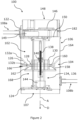
Figure 1 is an isometric view of a device for automatically releasing cremated ashes according to an embodiment of the present teachings; -
Figure 2 is a cross-sectional view of the device shown inFigure 1 ; and -
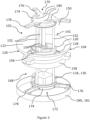
Figure 3 is an isometric view of internal components of the device shown inFigure 1 . - Referring firstly to
Figures 1 and2 , there is shown adevice 100 for automatically releasing cremated ashes. Thedevice 100 includes achamber 102 for containing cremated ashes, arelease mechanism 104 configured to selectively release cremated ashes contained in thechamber 102 to the external environment, and ahousing 106 arranged to at least partially house thechamber 102 and therelease mechanism 104. - In the illustrated embodiment, the
housing 106 is a substantially cylindrical shell. In alternative embodiments (not shown), thehousing 106 has any suitable shape, such as a prism with a polygonal profile for example. - In the illustrated embodiment, the
housing 106 is formed from a carbon fibre reinforced polymer. In alternative embodiments (not shown), thehousing 106 is formed from any suitable material, such as any suitable plastic or metallic material, for example. - The
device 100 includes twocamera mounts housing 106. In alternative embodiments (not shown), a single camera mount or more than two camera mounts are mounted to thehousing 106. Eachcamera mount camera 110 to thedevice 100 for capturing images of cremated ash released from thedevice 100. In the illustrated embodiment, eachcamera mount camera 110 to the device 100 (only onecamera 110 is visible in the view shown inFigure 1 ). - The
release mechanism 104 is configured to release cremated ashes contained in thechamber 102 from thedevice 100 substantially along a release axis A (represented via a dashed line inFigures 1 and2 ). - With reference to
Figures 2 and3 , therelease mechanism 104 includes an annularouter member 126. Theouter member 126 includes anoutlet 128 from thechamber 102. Therelease mechanism 104 further includes aninner member 130 at least partially radially inward of theouter member 126. Theinner member 130 and theouter member 126 have a common longitudinal axis A, which in the illustrated embodiment corresponds to the release axis A. In alternative embodiments (not shown), the release axis and the common longitudinal axis have different relative positions. - The
release mechanism 104 is configured to translate theinner member 130 and theouter member 126 relative to each other along the common longitudinal A axis from a first relative (closed) position (shown in uninterrupted line inFigure 2 ), in which release of cremated ashes in thechamber 102 through theoutlet 128 is inhibited, to a second relative (open) position (shown schematically in dashed line inFigure 2 ), in which release of cremated ashes in thechamber 102 through theoutlet 128 is enabled. In the following, "first relative position" and "closed position", and "second relative position" and "open position" shall be used interchangeably. - In the closed position, the
inner member 130 is in contact with theouter member 126 so as to cover theoutlet 128. In the open position, theinner member 130 is spaced from theouter member 126. In the open position, theinner member 130 is no longer covering theoutlet 128 so as to enable cremated ash contained in thechamber 102 to pass through theoutlet 128 and release from thedevice 100. - Advantageously, by translating the
inner member 130 and theouter member 126 relative to each other along the common longitudinal axis A from the closed position to the open position, the rate of release of cremated ashes from thechamber 102 via theoutlet 128 can be controlled. For example, in the open position, the spacing between theinner member 130 and theouter member 126 can be chosen such that the cremated ashes pass through a resulting gap between theouter member 126 and theinner member 130 at a desired rate of release. Moreover, the rate of release of cremated ashes from the device can be changed without changing the position of the release axis A. - In the illustrated embodiment, cremated ashes contained in the
chamber 102 are released to the external environment from anopening 107 in thehousing 106 at thesecond end 124 of thehousing 106 when therelease mechanism 104 is in the open position. - In the illustrated embodiment, the
outlet 128 is annular. In alternative embodiments (not shown), theoutlet 128 has any suitable shape. - In the illustrated embodiment, the
inner member 130 and theouter member 126 are formed from polylactide (PLA) via an additive manufacturing process. In alternative embodiments (not shown), theinner member 130 and theouter member 126 are formed from any suitable material, such as any suitable plastic or metallic material for example, via any suitable process. - In the illustrated embodiment, a distance between the
inner member 130 and thechamber 102 is greater in the open position relative to the closed position. Put another way, theinner member 130 moves away from thechamber 102 in a direction D (represented by an arrow inFigure 2 ) as theinner member 130 and theouter member 126 are translated relative to each other along the common longitudinal A axis from the closed position to the open position. - In alternative embodiments (not shown), the distance between the
inner member 130 and thechamber 102 is less in the open position relative to the closed position. In such embodiments, theinner member 130 may move towards the chamber 102 (upwards inFigure 2 ) as theinner member 130 and theouter member 126 are translated relative to each other along the common longitudinal A axis from the closed position to the open position. In such embodiments, theinner member 130 may be wholly located within thechamber 102 in the open position. In such embodiments, theinner member 130 is modified accordingly. - The
chamber 102 is partially defined by thehousing 106. In the illustrated embodiment, thechamber 102 is defined by aperipheral wall 164 of thehousing 106 and therelease mechanism 104. In alternative embodiments, thechamber 102 is not partially defined by the housing. For example, thechamber 102 may be partially defined by a peripheral wall which is separate to thehousing 106, and which may be at least partially housed within thehousing 106. - The
outer member 126 includes an annularsloping surface 132 converging towards theoutlet 128. In the illustrated embodiment, the annularsloping surface 132 converges along the common longitudinal axis A from afirst end 132a of the annularsloping surface 132 furthest from theoutlet 128 to asecond end 132b of the annularsloping surface 132 adjacent theoutlet 128. - The
chamber 102 is partially defined by the annularsloping surface 132. In the illustrated embodiment, the annularsloping surface 132 acts as a funnel, which guides cremated ashes in thechamber 102 towards theoutlet 128. - In the illustrated embodiment, the
outer member 126 is at least partially frustoconical. In alternative embodiments (not shown), theouter member 126 has any suitable shape. - The annular
sloping surface 132 of theouter member 126 forms a maximum angle with the common longitudinal axis A in the range of 30 to 60 degrees, preferably in the range of 40 to 50 degrees. In the illustrated embodiment, the annularsloping surface 132 of theouter member 126 forms a maximum angle with the common longitudinal axis A of approximately 45 degrees. Advantageously, these angles have been found to ensure that substantially all of the cremated ash in thechamber 102 is released through theoutlet 128 at a desired controlled rate in the open position. - In the illustrated embodiment, the annular
sloping surface 132 has a substantially straight profile as shown inFigure 2 . In alternative embodiments (not shown), the annularsloping surface 132 has any suitable profile. - In alternative embodiments (not shown), the
outer member 126 does not include the annularsloping surface 132, and, for example, may instead include a surface substantially parallel to or normal to the common longitudinal axis A. - In the illustrated embodiment, the common longitudinal axis A is an axis of rotational symmetry of the annular
sloping surface 132 of theouter member 126. - The
inner member 130 includes an annularsloping surface 158 arranged to contact theouter member 126 in the closed position. In the illustrated embodiment, theinner member 130 is partially dome shaped. The annularsloping surface 158 has the shape of a truncated dome. In alternative embodiments (not shown), the annularsloping surface 158 is dome-shaped, or has any suitable sloping shape. For example, the annularsloping surface 158 may have a substantially straight profile. - In the illustrated embodiment, cremated ash passing through the
outlet 128 in the open position flows over the annularsloping surface 158 of theinner member 130 before exiting thedevice 100. As such, theinner member 130 impedes the flow of cremated ash from thedevice 100 in the open position, helping to control the rate of release of cremated ash from thedevice 100. - In the illustrated embodiment, the common longitudinal axis A is an axis of rotational symmetry of the annular
sloping surface 158 of theinner member 130. - In the illustrated embodiment, an outer diameter of the annular
sloping surface 158 of theinner member 130 is greater than a diameter of theoutlet 128. As such, the annularsloping surface 158 projects radially outward from theoutlet 128, for example as shown inFigures 2 and3 . Advantageously, this helps ensure that cremated ash flows over a greater area of theinner member 130 when cremated ash is released from thedevice 100, to help control the release of the cremated ash from thedevice 100. - The annular
sloping surface 158 of theinner member 130 forms a maximum angle with the common longitudinal axis A in the range of 65 degrees to 85 degrees, preferably 70 degrees to 80 degrees. In the illustrated embodiment, the annularsloping surface 158 of theinner member 130 forms a maximum angle with the common longitudinal axis A of approximately 77 degrees. Advantageously, these angles have been found to maximise the volume of ash released from thedevice 100 in the open position, whilst helping to ensure a controlled release of the ashes from thedevice 100. - The annular
sloping surface 158 of theinner member 130 forms a minimum angle with the common longitudinal axis A in the range of 20 degrees to 40 degrees, preferably 25 degrees to 35 degrees. In the illustrated embodiment, the annularsloping surface 158 of theinner member 130 forms a minimum angle with the common longitudinal axis A of approximately 30 degrees. - In the illustrated embodiment, the annular
sloping surface 158 of theinner member 130 diverges along the common longitudinal axis A from afirst end 160 of the annularsloping surface 158 adjacent thechamber 102 to an opposedsecond end 162 of the annularsloping surface 158. In the illustrated embodiment, theouter member 126 is interposed between thechamber 102 and thesecond end 162 of the annularsloping surface 158. - In alternative embodiments (not shown), in which the distance between the
inner member 130 and thechamber 102 is less in the open position relative to the closed position, the annularsloping surface 158 of theinner member 130 converges along the common longitudinal axis A from a first end thereof adjacent thechamber 102 to an oppose second thereof, for example furthest from thechamber 102. - The
outer member 126 is fixed relative to thechamber 102. In the illustrated embodiment, the outer member is mounted to theperipheral wall 164 of thechamber 102, for example, via one or more fasteners, such as bolts. - In alternative embodiments (not shown), the
inner member 130 is instead fixed relative to thechamber 102. - The
outer member 126 includes anannular sealing member 166 configured to form a seal with theinner member 130 in the closed position. Theannular sealing member 166 may be formed from a flexible polymeric material, such as rubber for example. In the illustrated embodiment, theannular sealing member 166 is arranged adjacent to and around theoutlet 128. - In alternative embodiments (not shown), the
inner member 130 instead includes theannular sealing member 166. - The
release mechanism 104 includes an actuator arrangement 134 configured to translate theinner member 130 and theouter member 126 relative to each other along the common longitudinal axis A from the closed position to the open position. - In the illustrated embodiment, the actuator arrangement 134 is fixed relative to the
outer member 126, and is configured to translate theinner member 130 relative to theouter member 126. In alternative embodiments (not shown), the actuator arrangement 134 is fixed relative to theinner member 130, and is configured to translate theouter member 126 relative to theinner member 130. - In the illustrated embodiment, the actuator arrangement 134 includes a linear actuator 136 arranged to engage the
inner member 130. Actuation of the linear actuator 136 translates theinner member 130 and theouter member 126 relative to each other along the common longitudinal axis A. - The linear actuator 136 is fixed relative to the
outer member 126. In the illustrated embodiment, the linear actuator 136 and theouter member 126 are both fixed relative to thehousing 106. Actuation of the linear actuator 136 translates theinner member 130 relative to thehousing 106. - In the illustrated embodiment, the linear actuator 136 is a screw linear actuator configured to rotate a
screw 138 about an axis parallel to the common longitudinal axis A. Thescrew 138 is received in a threadedbore 140 of theinner member 130. Therelease mechanism 104 includes a guidingarrangement 142, discussed in more detail in the following, configured to inhibit relative rotational movement between theinner member 130 and theouter member 126 about the common longitudinal axis A. As such, rotation of thescrew 138 results in theinner member 130 translating relative to theouter member 126 along the common longitudinal axis A from the closed position to the open position. - In the illustrated embodiment, the linear actuator 136 incudes a
stepper motor 144 configured to rotate thescrew 138. Advantageously, thestepper motor 144 enables precise control of therelease mechanism 104. In alternative embodiments (not shown), the linear actuator 136 includes any suitable motor. - In alternative embodiments (not shown), the linear actuator 136 does not engage the
inner member 130, and instead engages theouter member 126, such that actuation of the linear actuator 136 translates theinner member 130 and theouter member 126 relative to each other along the common longitudinal axis A. In such embodiments, the linear actuator 136 may be fixed relative to theinner member 130 instead of theouter member 126, for example, theinner member 130 and the linear actuator 136 may both be fixed relative to thehousing 106. Actuation of the linear actuator 136 may translate theouter member 126 relative to thehousing 106. - In alternative embodiments (not shown), the actuator arrangement 134 includes any suitable actuator configured to translate the
inner member 130 and theouter member 126 relative to each from the closed position to the open position, for example, a hydraulic or pneumatic actuator. - In the illustrated embodiment, the guiding
arrangement 142 is configured to constrain relative movement between theinner member 130 and theouter member 126 to along the common longitudinal axis A. The guidingarrangement 142 includes three elongate guidingmembers 152 arranged substantially parallel to, and offset from, the common longitudinal axis A. In alternative embodiments (not shown), the guidingarrangement 142 instead includes one, two or more than three guidingmembers 152. - The guiding
members 152 are fixed relative to theouter member 126. - The
inner member 130 includescomplimentary bores 154, each arranged to receive a respective one of the guidingmembers 152. Thebores 154 and the guidingmembers 152 are configured such that theinner member 130 can translate relative to the guidingmembers 152 along the common longitudinal axis A. - In the illustrated embodiment, a linear bearing (not shown) is mounted within each of the
bores 154. Each linear bearing is interposed between therespective bore 154 and the respective guidingmember 152. Advantageously, the linear bearings help to reduce friction between the guidingmembers 152 and theinner member 130, and thus help to provide smooth relative translation between theinner member 130 and the guidingarrangement 142. In the illustrated embodiment, thebores 154 pass through acentral portion 156 of theinner member 130. Thecentral portion 156 is radially inward of the annularsloping surface 158 of theinner member 130. Advantageously, such a configuration helps to improve the compactness of thedevice 100. - In alternative embodiments (not shown), the guiding
members 152 are fixed relative to theinner member 130. In such embodiments, the guidingmembers 152 may be arranged so as to be received incomplimentary bores 154 in theouter member 126, and such that theouter member 126 can translate relative to the guidingmembers 152 along the common longitudinal axis A. - In alternative embodiments (not shown), the
device 100 includes anysuitable guiding arrangement 142. Alternatively, in embodiments in which theinner member 130 and theouter member 126 are translated relative to each from the closed position to the open position without thescrew 138, thedevice 100 may not include the guidingarrangement 142. - The
device 100 further includes acontroller 146 configured to control the actuator arrangement 134. In the illustrated embodiment, thecontroller 146 includes a global positioning device (e.g. GPS), an altimeter, and a communication device for receiving wireless communication signals (e.g. 5G). - The
controller 146 may be configured to control the actuator arrangement 134 based on at least one predetermined condition, such as: a predetermined release time; a predetermined altitude of thedevice 100; a predetermined global position of thedevice 100; and a communication signal received by thecontroller 146. For example, thecontroller 146 may be configured to control the actuator arrangement 134 to translate theinner member 130 and theouter member 126 relative to each other along the common longitudinal axis A from the closed position to the open position based on the at least one predetermined condition. - With further reference to
Figure 1 , eachcamera mount elongate member 112 extending away from thehousing 106. Eachelongate member 112 includes a first end 114 mounted to thehousing 106. Eachelongate member 112 includes a second end 116 opposite to the first end 114. Eachelongate member 112 is configured such that acamera 110 is mountable to the second end 116 of theelongate member 112. - In the illustrated embodiment, each
elongate member 112 is a rod. In alternative embodiments, eachelongate member 112 has any suitable shape. - In the illustrated embodiment, each
camera mount elongate member 112. The bracket 118 is attached to one of thecameras 110 via acamera casing 120 arranged to at last partially encase therespective camera 110. In alternative embodiments (not shown), each bracket 118 is directly secured to one of thecameras 110. - The
device 100 is configured such that the camera mounts 108a, 108b dismount from thehousing 106 when the camera mounts 108a, 108b impact a ground surface at a speed in the range of 3 to 5 meters per second. - In the illustrated embodiment, the first end 114 of each
elongate member 112 is mounted to thehousing 106 via a connector 115 secured to thehousing 106. Each connector 115 includes a crumple zone configured to release the respectiveelongate member 112 from the connector 115, and thus from thehousing 106, when therespective camera mount - Advantageously, such a configuration of the camera mounts 108a, 108b helps to minimise damage to the
housing 106, for example when thedevice 100 is returning to the ground from a high-altitude (e.g. the stratosphere or above), for example via a parachute or other decelerating means. - In alternative embodiments (not shown), the
device 100 includes a plurality of cables, each cable connecting one of the camera mounts 108a, 108b to thehousing 106. For example, a first end of each cable may be secured to therespective camera casing 120 and a second end of each cable may be secured to thehousing 106 via one of thefasteners 182. Advantageously, the cables help ensure that the camera mounts 108a, 108b remain connected to thehousing 106 after they are dismounted from thehousing 106, to limit a separation distance between the camera mounts 108a, 108b and thehousing 106 after thedevice 100 has impacted a ground surface, for example. - In alternative embodiments (not shown), the
device 100 is configured such that the camera mounts 108a, 108b dismount from thehousing 106 when the camera mounts 108a, 108b impact a ground surface at a speed in the range of 3 to 5 meters per second via any suitable means. - In alternative embodiments (not shown), the
device 100 is configured such that one or more of the camera mounts 108a, 108b do not dismount from thehousing 106 when said one ormore camera mounts first camera mount 108a and asecond camera mount 108b. Thefirst camera mount 108a and thesecond camera mount 108b are spaced radially from each other about the release axis A by an angle in the range of 150 to 210 degrees, preferably 170 to 190 degrees. In the illustrated embodiment, thefirst camera mount 108a and thesecond camera mount 108b are spaced radially from each other about the release axis A by approximately 180 degrees. - In alternative embodiments (not shown), the camera mounts 108a, 108b are not spaced radially from each other about the release axis A.
- In the illustrated embodiment, the camera mounts 108a, 108b are spaced from each other along the release axis A. In the exemplary embodiment shown in
Figures 1 and2 , thefirst camera mount 108a is positioned adjacent afirst end 122 of thehousing 106, and thesecond camera mount 108b is positioned adjacent a substantially oppositesecond end 124 of thehousing 106. - In alternative embodiments (not shown), the camera mounts 108a, 108b are not spaced from each other along the release axis A.
- The
device 100 is modular and includes a plurality of modules, each module releasably mounted to at least one other module. By 'releasably mounted', it is intended to mean that each module can be mounted to and dismounted from at least one other module by using only hand tools (e.g. screw driver, allen key, or pliers) or no tools at all. - The plurality of modules includes a
controller module 148, anactuator module 168, and ahousing module 106. In the illustrated embodiment, the housing module corresponds to thehousing 106. - In the illustrated embodiment, the
actuator module 168 includes the actuator arrangement 134, theinner member 130 and the guidingarrangement 142. - The
actuator module 168 is releasably mounted to thehousing module 106. - With reference to
Figure 3 , theactuator module 168 further includes a first mountingmember 170 and a second mountingmember 172. Theactuator module 168 is releasably mounted to thefirst end 122 of the housing module via the first mountingmember 170. Theactuator module 168 is releasably mounted to thesecond end 124 of thehousing module 106 via the second mountingmember 172. - The first and second mounting
members hub 174 and threelegs 176 extending radially outward from thehub 174. Eachleg 176 is mounted to thehousing module 106 via a fastener, such as a bolt, passing through theperipheral wall 164 of thehousing module 106 and received in a (e.g. threaded)hole 178 in theleg 176. In alternative embodiments (not shown), each mountingmember legs 176. - In the illustrated embodiment, the guiding
arrangement 142 is mounted to thehubs 174 of the first mountingmember 170 and the second mountingmember 172. The actuator arrangement 134 is mounted to thehub 174 of the second mountingmember 172. Thelegs 176 of the second mountingmember 172 are mounted to an annular member 180 receivable within thehousing module 106 so as to form a snug fit with an internal surface of theperipheral wall 164. By 'snug fit' it is intended to mean that a peripheral exterior surface 181 of the annular member 180 abuts against the internal surface of theperipheral wall 164 when the annular member 180 is received in thehousing module 106. The annular member 180 helps increase the rigidity of thehousing module 106 at thesecond end 124 thereof. - The
controller module 148 houses thecontroller 146. Thecontroller module 148 also houses other components such as abattery 149 arranged to power thecontroller 146 and the actuator arrangement 134. - The
controller module 148 is releasably mounted to thechamber 102. In the illustrated embodiment, thecontroller module 148 is releasably mounted to thehousing module 106 and theactuator module 168. Thecontroller module 148 is positioned at or towards thefirst end 122 of thehousing module 106 - The
controller module 148 is releasably mounted to thefirst end 122 of thehousing module 106 via a plurality offasteners 182, such as bolts, passing through theperipheral wall 164 of thehousing module 106 and bores in thecontroller module 148. Thecontroller module 148 is releasably mounted to theactuator module 168 via a plurality of fasteners (not shown), such as bolts, passing through thecontroller module 148 and bores 184 in thehub 174 of the first mountingmember 170. - In alternative embodiments (not shown), the
controller module 148 is mounted to only one of thehousing module 106 or theactuator module 168. - The
controller module 148 provides a closure to aninlet 150 to thechamber 102 when thecontroller module 148 is mounted to thechamber 102. Thedevice 100 is configured such that cremated ashes can be introduced into thechamber 102 via theinlet 150 when thecontroller module 148 is dismounted from thechamber 102. In the illustrated embodiment, theinlet 150 is formed betweenadjacent legs 176 of the first mountingmember 170. - In the illustrated embodiment, the
release mechanism 104 is releasably mounted to thehousing module 106. Theouter member 126 is releasably mounted to thehousing module 106 via one or more fasteners (not shown), such as bolts. As previously described, theinner member 130 and the guidingarrangement 142 form part of theactuator module 168, which is releasably mounted to thehousing module 106. - In the foregoing description, the
controller module 148, theactuator module 168, and thehousing module 106 are releasably mounted to the corresponding modules via fasteners. In alternative embodiments (not shown), one or more of thecontroller module 148, theactuator module 168, and thehousing module 106 are releasably mounted to the corresponding modules via any suitable releasable mounting arrangement, such as a bayonet-type fitting, for example. - In the following, a method of automatically releasing cremated ashes via the
device 100 will be outlined. - In a first step, cremated ashes are introduced into the
chamber 102. - Subsequently, the
device 100 may be elevated, for example, to the stratosphere or above. Thedevice 100 may be elevated via a self-propelled vehicle, such as an aircraft or a rocket, for example. The aircraft may be a lighter-than-air aircraft such as a weather balloon, for example. - In a subsequent step, the
inner member 130 and theouter member 126 are automatically translated relative to each other along the common longitudinal axis A from the closed position to the open position, to enable the cremated ashes contained in thechamber 102 to release from thedevice 100 via theoutlet 128. - In the foregoing description, the
device 100 is configured to automatically release cremated ashes to the external environment. In alternative embodiments (not shown), thedevice 100 is configured to automatically release any suitable granular material or any suitable liquid contained in thechamber 102 to the external environment via theoutlet 128. - In the foregoing description, the
outer member 126 includes theoutlet 128. In alternative embodiments (not shown), theouter member 126, suitably modified, includes a plurality ofoutlets 128 from thechamber 102. In such embodiments, theinner member 130, suitably modified, may contact theouter member 126 so as to cover theoutlets 128 in the closed position. Alternatively, therelease mechanism 104 may include a plurality ofinner members 130, each configured to contact theouter member 126 so as to cover one of theoutlets 128 in the closed position. The plurality ofoutlets 128 may be distributed radially about the common longitudinal axis A.
Claims (15)
- A device for automatically releasing cremated ashes, comprising:a chamber for containing cremated ashes; anda release mechanism configured to selectively release cremated ashes contained in the chamber to the external environment, the release mechanism comprising an annular outer member, and an inner member at least partially radially inward of the outer member, the outer member comprising an outlet from the chamber,wherein the release mechanism is configured to translate the inner member and the outer member relative to each other along a common longitudinal axis from a first relative position, in which release of cremated ashes in the chamber through the outlet is inhibited, to a second relative position, in which release of cremated ashes in the chamber through the outlet is enabled, wherein, in the first relative position, the inner member is in contact with the outer member so as to cover the outlet, and wherein, in the second relative position, the inner member is spaced from the outer member.
- The device of claim 1, wherein the outer member comprises an annular sloping surface converging towards the outlet; optionally, wherein the outer member is at least partially frustoconical; optionally, wherein the annular sloping surface of the outer member forms a maximum angle with the common longitudinal axis in the range of 30 to 60 degrees, preferably in the range of 40 to 50 degrees, for example approximately 45 degrees.
- The device of any preceding claim, wherein the release mechanism comprises an actuator arrangement configured to translate the inner member and the outer member relative to each other along the common longitudinal axis from the first relative position to the second relative position; optionally, wherein the actuator arrangement comprises a linear actuator arranged to engage one of the inner member and the outer member, and wherein actuation of the linear actuator translates the inner member and the outer member relative to each other along the common longitudinal axis; optionally, wherein the linear actuator is a screw linear actuator, and/or wherein the linear actuator comprises a stepper motor.
- The device of claim 3, further comprising a controller configured to control the actuator arrangement; optionally, wherein the controller is configured to control the actuator arrangement based on at least one predetermined condition, such as: a predetermined release time; a predetermined altitude of the device; a predetermined global position of the device; and a communication signal received by the controller.
- The device of claim 4, further comprising a controller module releasably mounted to the chamber, wherein the controller is housed in the controller module; optionally, wherein the controller module provides a closure to an inlet to the chamber when the controller module is mounted to the chamber, and wherein the device is configured such that cremated ashes can be introduced into the chamber via the inlet when the controller module is dismounted from the chamber.
- The device of any preceding claim, wherein the inner member comprises an annular sloping surface arranged to contact the outer member in the first relative position; optionally, wherein the inner member is at least partially dome shaped, and/or, wherein the outlet is annular, and wherein an outer diameter of the annular sloping surface of the inner member is greater than a diameter of the outlet.
- The device of any preceding claim, wherein a distance between the inner member and the chamber is greater in the second relative position relative to the first relative position; optionally, wherein the inner member comprises an annular sloping surface arranged to contact the outer member in the first relative position, wherein said annular sloping surface diverges along the common longitudinal axis from a first end thereof adjacent the chamber to an opposed second end thereof.
- The device of any preceding claim, wherein the outer member is fixed relative to the chamber; optionally, wherein the outer member is mounted to a peripheral wall of the chamber, for example, via one or more fasteners.
- The device of any preceding claim, wherein the outer member or the inner member comprises an annular sealing member configured to form a seal with the other of the outer member or the inner member in the first relative position; optionally, wherein the sealing member is formed from a flexible polymeric material, such as rubber.
- The device of any preceding claim, wherein the release mechanism comprises a guiding arrangement configured to inhibit relative rotational movement between the inner member and the outer member about the common longitudinal axis; optionally, wherein the guiding arrangement is configured to constrain relative movement between the inner member and the outer member to along the common longitudinal axis.
- The device of claim 10, wherein the guiding arrangement comprises one or more elongate guiding members arranged substantially parallel to, and offset from, the common longitudinal axis, and wherein one of the inner member and the outer member comprises one or more complimentary bores, each arranged to receive a respective one of the one or more guiding members.
- The device of claim 11, wherein the inner member comprises the one or more bores, the one or more bores passing through a central portion of the inner member; optionally, wherein the central portion is radially inward of an annular sloping surface of the inner member arranged to contact the outer member in the first relative position.
- The device of any preceding claim, further comprising a housing, wherein the chamber and the release mechanism are at least partially housed within the housing; optionally, wherein the housing is substantially cylindrical, and/or wherein the chamber is partially defined by the housing.
- The device of claim 13, further comprising one or more camera mounts mounted to the housing, each camera mount for mounting a camera to the device for capturing images of cremated ash released from the device; optionally, further comprising one or more cameras, each camera mounted to one of the one or more camera mounts.
- A method of automatically releasing cremated ashes, comprising the steps of:providing a device comprising a chamber for containing cremated ashes, and a release mechanism configured to selectively release cremated ashes contained in the chamber to the external environment, the release mechanism comprising an annular outer member, and an inner member at least partially radially inward of the outer member, the outer member comprising an outlet from the chamber;inserting cremated ashes into the chamber; andautomatically translating the inner member and the outer member relative to each other along a common longitudinal axis from a first relative position, in which release of the cremated ashes in the chamber through the outlet is inhibited, to a second relative position, in which release of cremated ashes in the chamber through the outlet is enabled, wherein, in the first relative position, the inner member is in contact with the outer member so as to cover the outlet, and wherein, in the second relative position, the inner member is spaced from the outer member.
Applications Claiming Priority (1)
| Application Number | Priority Date | Filing Date | Title |
|---|---|---|---|
| GB2211401.1A GB2621165A (en) | 2022-08-04 | 2022-08-04 | A device |
Publications (3)
| Publication Number | Publication Date |
|---|---|
| EP4316447A1 true EP4316447A1 (en) | 2024-02-07 |
| EP4316447C0 EP4316447C0 (en) | 2025-07-02 |
| EP4316447B1 EP4316447B1 (en) | 2025-07-02 |
Family
ID=84546250
Family Applications (1)
| Application Number | Title | Priority Date | Filing Date |
|---|---|---|---|
| EP23189485.8A Active EP4316447B1 (en) | 2022-08-04 | 2023-08-03 | A device for automatically releasing cremated ashes |
Country Status (5)
| Country | Link |
|---|---|
| US (1) | US12414893B2 (en) |
| EP (1) | EP4316447B1 (en) |
| CA (1) | CA3208178A1 (en) |
| ES (1) | ES3036361T3 (en) |
| GB (1) | GB2621165A (en) |
Cited By (1)
| Publication number | Priority date | Publication date | Assignee | Title |
|---|---|---|---|---|
| SE2450406A1 (en) * | 2024-04-18 | 2025-10-19 | UASolutions AB | Controlled mechanism for remote scattering ashes from a passive urn |
Citations (2)
| Publication number | Priority date | Publication date | Assignee | Title |
|---|---|---|---|---|
| US20190337619A1 (en) * | 2018-05-02 | 2019-11-07 | Daniel J. O'Hara | Aerial dispersal system for cremated remains |
| CN111184959A (en) * | 2018-11-15 | 2020-05-22 | 陕西安格锐信息科技有限公司 | Forest fire-extinguishing equipment based on unmanned aerial vehicle |
Family Cites Families (14)
| Publication number | Priority date | Publication date | Assignee | Title |
|---|---|---|---|---|
| US4877203A (en) * | 1987-09-18 | 1989-10-31 | Harden Bonnie J | Method and apparatus for dispersing cremated remains |
| US5005784A (en) * | 1987-09-18 | 1991-04-09 | Harden Bonnie J | Method and apparatus for dispersing cremated remains |
| NL9101029A (en) * | 1991-06-13 | 1993-01-04 | Zeger Cornelis Houtop | Closure device for an invertable container for bulk materials |
| US5564260A (en) * | 1995-09-01 | 1996-10-15 | West; Joan B. | Dispersal of cremated remains |
| US20090229097A1 (en) * | 2008-03-11 | 2009-09-17 | Crandlemire Scott H | Human and animal cremated ashes automated spreading device |
| US20110220733A1 (en) * | 2010-03-15 | 2011-09-15 | Larson Kris K | Cremated remains scattering apparatus |
| US8739374B2 (en) * | 2013-01-28 | 2014-06-03 | Wallace N. Brown | Aerial disposal and dispersal of cremated remains going out with a bang |
| NL2014660B1 (en) * | 2015-04-17 | 2016-12-30 | Johannes Antonius Maria Tibosch Henricus | device, application of the device and method for spreading cremation ash. |
| JP6106706B2 (en) * | 2015-04-22 | 2017-04-05 | 和也 石坂 | Scattering drone and drone loading device |
| NL2017537B1 (en) * | 2016-09-26 | 2018-04-04 | Klaas Jan Laurens Wouter | Autonomous urn for delivering powdered material remains from the urn, as well as a method for delivering powdered material remains to the bottom |
| CN109132597A (en) * | 2018-09-13 | 2019-01-04 | 辽宁瑞泊科技有限公司 | Accurate powder launches storehouse |
| UA120337C2 (en) * | 2019-03-12 | 2019-11-11 | Андрій Анатолійович Зубок | DEVICE FOR DEVELOPING DUST FROM AN UNMANNED AIRCRAFT (UAV) AND METHOD FOR DEVELOPING DUST |
| FR3123561B1 (en) * | 2021-06-07 | 2023-06-02 | Franck Siguier | DEVICE FOR THE DISPERSION OF FUNERAL ASHES FROM A REMOTE PILOT AIRCRAFT |
| US12097407B2 (en) * | 2021-08-06 | 2024-09-24 | James Manser | Frangible golf ball |
-
2022
- 2022-08-04 GB GB2211401.1A patent/GB2621165A/en active Pending
-
2023
- 2023-07-31 CA CA3208178A patent/CA3208178A1/en active Pending
- 2023-08-03 US US18/229,688 patent/US12414893B2/en active Active
- 2023-08-03 EP EP23189485.8A patent/EP4316447B1/en active Active
- 2023-08-03 ES ES23189485T patent/ES3036361T3/en active Active
Patent Citations (2)
| Publication number | Priority date | Publication date | Assignee | Title |
|---|---|---|---|---|
| US20190337619A1 (en) * | 2018-05-02 | 2019-11-07 | Daniel J. O'Hara | Aerial dispersal system for cremated remains |
| CN111184959A (en) * | 2018-11-15 | 2020-05-22 | 陕西安格锐信息科技有限公司 | Forest fire-extinguishing equipment based on unmanned aerial vehicle |
Cited By (1)
| Publication number | Priority date | Publication date | Assignee | Title |
|---|---|---|---|---|
| SE2450406A1 (en) * | 2024-04-18 | 2025-10-19 | UASolutions AB | Controlled mechanism for remote scattering ashes from a passive urn |
Also Published As
| Publication number | Publication date |
|---|---|
| EP4316447C0 (en) | 2025-07-02 |
| GB2621165A (en) | 2024-02-07 |
| GB202211401D0 (en) | 2022-09-21 |
| US12414893B2 (en) | 2025-09-16 |
| ES3036361T3 (en) | 2025-09-18 |
| EP4316447B1 (en) | 2025-07-02 |
| CA3208178A1 (en) | 2024-02-04 |
| US20240041686A1 (en) | 2024-02-08 |
Similar Documents
| Publication | Publication Date | Title |
|---|---|---|
| EP4316447B1 (en) | A device for automatically releasing cremated ashes | |
| CN104527979B (en) | Space base teargas bullet automatic feeder | |
| DE60124224T2 (en) | RPV, IN PARTICULAR FOR MONITORING OR INVESTIGATION | |
| KR101610802B1 (en) | Unmanned Aerial Vehicle System For Locking Gimbal | |
| RU2473455C2 (en) | Compact drone system | |
| US10351249B2 (en) | Parachute deployment apparatus, system and method of use | |
| EP3570945B1 (en) | Swiming and diving scooter with camera | |
| EP0164557A1 (en) | Automotive inspection and maintenance vehicle | |
| JP2016215874A (en) | Capture device | |
| US9731811B2 (en) | Payload shroud for air vehicle | |
| US20070205327A1 (en) | Aircraft sensor pod assembly | |
| DE102015008255A1 (en) | Defense drone to intercept a small drone | |
| WO2018033812A1 (en) | Administration of substances to animals | |
| IL264381A (en) | Device and method for removing a parachute | |
| US20190118927A1 (en) | Aircraft external viewing system, apparatus, and method | |
| US20250224072A1 (en) | Adjustable camera mount | |
| DE102019109127A1 (en) | Drone-based air and collision surveillance system | |
| JP6677532B2 (en) | Underwater remote control vehicle, container inspection device, container inspection method | |
| CN109436344A (en) | Airborne photography gondola based on parachute ballistic trajectory | |
| US11878801B2 (en) | Adjustable aft pivot assembly release component | |
| CN218400958U (en) | Pollution sources investigation unmanned aerial vehicle | |
| CN110711335A (en) | Self-correcting adjustable fire monitor head | |
| CN208119422U (en) | Agricultural spray unmanned plane based on remote sensing technology | |
| CN208233377U (en) | A kind of unmanned plane to pan | |
| DE102017127027B4 (en) | Ground station for a battery-operated unmanned aerial vehicle and battery-operated unmanned aerial vehicle |
Legal Events
| Date | Code | Title | Description |
|---|---|---|---|
| PUAI | Public reference made under article 153(3) epc to a published international application that has entered the european phase |
Free format text: ORIGINAL CODE: 0009012 |
|
| STAA | Information on the status of an ep patent application or granted ep patent |
Free format text: STATUS: THE APPLICATION HAS BEEN PUBLISHED |
|
| AK | Designated contracting states |
Kind code of ref document: A1 Designated state(s): AL AT BE BG CH CY CZ DE DK EE ES FI FR GB GR HR HU IE IS IT LI LT LU LV MC ME MK MT NL NO PL PT RO RS SE SI SK SM TR |
|
| STAA | Information on the status of an ep patent application or granted ep patent |
Free format text: STATUS: REQUEST FOR EXAMINATION WAS MADE |
|
| 17P | Request for examination filed |
Effective date: 20240718 |
|
| RBV | Designated contracting states (corrected) |
Designated state(s): AL AT BE BG CH CY CZ DE DK EE ES FI FR GB GR HR HU IE IS IT LI LT LU LV MC ME MK MT NL NO PL PT RO RS SE SI SK SM TR |
|
| GRAP | Despatch of communication of intention to grant a patent |
Free format text: ORIGINAL CODE: EPIDOSNIGR1 |
|
| STAA | Information on the status of an ep patent application or granted ep patent |
Free format text: STATUS: GRANT OF PATENT IS INTENDED |
|
| INTG | Intention to grant announced |
Effective date: 20240902 |
|
| GRAJ | Information related to disapproval of communication of intention to grant by the applicant or resumption of examination proceedings by the epo deleted |
Free format text: ORIGINAL CODE: EPIDOSDIGR1 |
|
| STAA | Information on the status of an ep patent application or granted ep patent |
Free format text: STATUS: REQUEST FOR EXAMINATION WAS MADE |
|
| INTC | Intention to grant announced (deleted) | ||
| GRAP | Despatch of communication of intention to grant a patent |
Free format text: ORIGINAL CODE: EPIDOSNIGR1 |
|
| STAA | Information on the status of an ep patent application or granted ep patent |
Free format text: STATUS: GRANT OF PATENT IS INTENDED |
|
| INTG | Intention to grant announced |
Effective date: 20250129 |
|
| GRAS | Grant fee paid |
Free format text: ORIGINAL CODE: EPIDOSNIGR3 |
|
| GRAA | (expected) grant |
Free format text: ORIGINAL CODE: 0009210 |
|
| STAA | Information on the status of an ep patent application or granted ep patent |
Free format text: STATUS: THE PATENT HAS BEEN GRANTED |
|
| AK | Designated contracting states |
Kind code of ref document: B1 Designated state(s): AL AT BE BG CH CY CZ DE DK EE ES FI FR GB GR HR HU IE IS IT LI LT LU LV MC ME MK MT NL NO PL PT RO RS SE SI SK SM TR |
|
| REG | Reference to a national code |
Ref country code: GB Ref legal event code: FG4D |
|
| REG | Reference to a national code |
Ref country code: CH Ref legal event code: EP |
|
| REG | Reference to a national code |
Ref country code: DE Ref legal event code: R096 Ref document number: 602023004468 Country of ref document: DE |
|
| REG | Reference to a national code |
Ref country code: IE Ref legal event code: FG4D |
|
| U01 | Request for unitary effect filed |
Effective date: 20250723 |
|
| U07 | Unitary effect registered |
Designated state(s): AT BE BG DE DK EE FI FR IT LT LU LV MT NL PT RO SE SI Effective date: 20250731 |
|
| REG | Reference to a national code |
Ref country code: ES Ref legal event code: FG2A Ref document number: 3036361 Country of ref document: ES Kind code of ref document: T3 Effective date: 20250918 |
|
| U20 | Renewal fee for the european patent with unitary effect paid |
Year of fee payment: 3 Effective date: 20251017 |
|
| PG25 | Lapsed in a contracting state [announced via postgrant information from national office to epo] |
Ref country code: IS Free format text: LAPSE BECAUSE OF FAILURE TO SUBMIT A TRANSLATION OF THE DESCRIPTION OR TO PAY THE FEE WITHIN THE PRESCRIBED TIME-LIMIT Effective date: 20251102 |
|
| PG25 | Lapsed in a contracting state [announced via postgrant information from national office to epo] |
Ref country code: NO Free format text: LAPSE BECAUSE OF FAILURE TO SUBMIT A TRANSLATION OF THE DESCRIPTION OR TO PAY THE FEE WITHIN THE PRESCRIBED TIME-LIMIT Effective date: 20251002 |
|
| PG25 | Lapsed in a contracting state [announced via postgrant information from national office to epo] |
Ref country code: HR Free format text: LAPSE BECAUSE OF FAILURE TO SUBMIT A TRANSLATION OF THE DESCRIPTION OR TO PAY THE FEE WITHIN THE PRESCRIBED TIME-LIMIT Effective date: 20250702 |
|
| PG25 | Lapsed in a contracting state [announced via postgrant information from national office to epo] |
Ref country code: GR Free format text: LAPSE BECAUSE OF FAILURE TO SUBMIT A TRANSLATION OF THE DESCRIPTION OR TO PAY THE FEE WITHIN THE PRESCRIBED TIME-LIMIT Effective date: 20251003 |
|
| PG25 | Lapsed in a contracting state [announced via postgrant information from national office to epo] |
Ref country code: CZ Free format text: LAPSE BECAUSE OF FAILURE TO SUBMIT A TRANSLATION OF THE DESCRIPTION OR TO PAY THE FEE WITHIN THE PRESCRIBED TIME-LIMIT Effective date: 20250702 |
|
| PGFP | Annual fee paid to national office [announced via postgrant information from national office to epo] |
Ref country code: IE Payment date: 20251024 Year of fee payment: 3 |
|
| PG25 | Lapsed in a contracting state [announced via postgrant information from national office to epo] |
Ref country code: PL Free format text: LAPSE BECAUSE OF FAILURE TO SUBMIT A TRANSLATION OF THE DESCRIPTION OR TO PAY THE FEE WITHIN THE PRESCRIBED TIME-LIMIT Effective date: 20250702 |
|
| PG25 | Lapsed in a contracting state [announced via postgrant information from national office to epo] |
Ref country code: RS Free format text: LAPSE BECAUSE OF FAILURE TO SUBMIT A TRANSLATION OF THE DESCRIPTION OR TO PAY THE FEE WITHIN THE PRESCRIBED TIME-LIMIT Effective date: 20251002 |
|
| PGFP | Annual fee paid to national office [announced via postgrant information from national office to epo] |
Ref country code: ES Payment date: 20251030 Year of fee payment: 3 |
|
| PG25 | Lapsed in a contracting state [announced via postgrant information from national office to epo] |
Ref country code: SM Free format text: LAPSE BECAUSE OF FAILURE TO SUBMIT A TRANSLATION OF THE DESCRIPTION OR TO PAY THE FEE WITHIN THE PRESCRIBED TIME-LIMIT Effective date: 20250702 |
|
| PG25 | Lapsed in a contracting state [announced via postgrant information from national office to epo] |
Ref country code: SK Free format text: LAPSE BECAUSE OF FAILURE TO SUBMIT A TRANSLATION OF THE DESCRIPTION OR TO PAY THE FEE WITHIN THE PRESCRIBED TIME-LIMIT Effective date: 20250702 |
|
| PLBE | No opposition filed within time limit |
Free format text: ORIGINAL CODE: 0009261 |
|
| STAA | Information on the status of an ep patent application or granted ep patent |
Free format text: STATUS: NO OPPOSITION FILED WITHIN TIME LIMIT |
|
| REG | Reference to a national code |
Ref country code: CH Ref legal event code: L10 Free format text: ST27 STATUS EVENT CODE: U-0-0-L10-L00 (AS PROVIDED BY THE NATIONAL OFFICE) Effective date: 20260518 |
|
| 26N | No opposition filed |
Effective date: 20260407 |
|
| PG25 | Lapsed in a contracting state [announced via postgrant information from national office to epo] |
Ref country code: MC Free format text: LAPSE BECAUSE OF FAILURE TO SUBMIT A TRANSLATION OF THE DESCRIPTION OR TO PAY THE FEE WITHIN THE PRESCRIBED TIME-LIMIT Effective date: 20250702 |