EP4316284A1 - Induction heating device - Google Patents
Induction heating device Download PDFInfo
- Publication number
- EP4316284A1 EP4316284A1 EP22780844.1A EP22780844A EP4316284A1 EP 4316284 A1 EP4316284 A1 EP 4316284A1 EP 22780844 A EP22780844 A EP 22780844A EP 4316284 A1 EP4316284 A1 EP 4316284A1
- Authority
- EP
- European Patent Office
- Prior art keywords
- circuit
- susceptor
- induction heating
- electric power
- mode
- Prior art date
- Legal status (The legal status is an assumption and is not a legal conclusion. Google has not performed a legal analysis and makes no representation as to the accuracy of the status listed.)
- Pending
Links
- 238000010438 heat treatment Methods 0.000 title claims abstract description 361
- 230000006698 induction Effects 0.000 title claims abstract description 181
- 239000000443 aerosol Substances 0.000 claims abstract description 131
- 239000000126 substance Substances 0.000 claims abstract description 92
- 230000008859 change Effects 0.000 claims description 21
- 238000001816 cooling Methods 0.000 claims description 15
- 230000007423 decrease Effects 0.000 claims description 7
- 238000000034 method Methods 0.000 description 239
- 230000008569 process Effects 0.000 description 211
- 238000001514 detection method Methods 0.000 description 34
- 230000004044 response Effects 0.000 description 29
- 230000006866 deterioration Effects 0.000 description 12
- 230000009471 action Effects 0.000 description 10
- 230000003213 activating effect Effects 0.000 description 10
- 239000003990 capacitor Substances 0.000 description 8
- 238000007599 discharging Methods 0.000 description 7
- 230000001965 increasing effect Effects 0.000 description 6
- 230000007704 transition Effects 0.000 description 6
- 230000006399 behavior Effects 0.000 description 4
- 238000004891 communication Methods 0.000 description 4
- 241000208125 Nicotiana Species 0.000 description 3
- 235000002637 Nicotiana tabacum Nutrition 0.000 description 3
- DNIAPMSPPWPWGF-UHFFFAOYSA-N Propylene glycol Chemical compound CC(O)CO DNIAPMSPPWPWGF-UHFFFAOYSA-N 0.000 description 3
- 230000002159 abnormal effect Effects 0.000 description 3
- 238000013459 approach Methods 0.000 description 3
- 239000007788 liquid Substances 0.000 description 3
- PEDCQBHIVMGVHV-UHFFFAOYSA-N Glycerine Chemical compound OCC(O)CO PEDCQBHIVMGVHV-UHFFFAOYSA-N 0.000 description 2
- 230000005540 biological transmission Effects 0.000 description 2
- 230000003247 decreasing effect Effects 0.000 description 2
- 230000003111 delayed effect Effects 0.000 description 2
- 238000010586 diagram Methods 0.000 description 2
- 230000005669 field effect Effects 0.000 description 2
- 230000001939 inductive effect Effects 0.000 description 2
- 238000002307 isotope ratio mass spectrometry Methods 0.000 description 2
- 239000003550 marker Substances 0.000 description 2
- 239000000463 material Substances 0.000 description 2
- 238000005259 measurement Methods 0.000 description 2
- 239000004065 semiconductor Substances 0.000 description 2
- 239000007787 solid Substances 0.000 description 2
- SNICXCGAKADSCV-JTQLQIEISA-N (-)-Nicotine Chemical compound CN1CCC[C@H]1C1=CC=CN=C1 SNICXCGAKADSCV-JTQLQIEISA-N 0.000 description 1
- HBBGRARXTFLTSG-UHFFFAOYSA-N Lithium ion Chemical compound [Li+] HBBGRARXTFLTSG-UHFFFAOYSA-N 0.000 description 1
- 230000000694 effects Effects 0.000 description 1
- 239000003571 electronic cigarette Substances 0.000 description 1
- 230000006870 function Effects 0.000 description 1
- 235000011187 glycerol Nutrition 0.000 description 1
- 230000036541 health Effects 0.000 description 1
- 238000003780 insertion Methods 0.000 description 1
- 230000037431 insertion Effects 0.000 description 1
- 229910001416 lithium ion Inorganic materials 0.000 description 1
- 229910044991 metal oxide Inorganic materials 0.000 description 1
- 150000004706 metal oxides Chemical class 0.000 description 1
- 230000004048 modification Effects 0.000 description 1
- 238000012986 modification Methods 0.000 description 1
- 229960002715 nicotine Drugs 0.000 description 1
- SNICXCGAKADSCV-UHFFFAOYSA-N nicotine Natural products CN1CCCC1C1=CC=CN=C1 SNICXCGAKADSCV-UHFFFAOYSA-N 0.000 description 1
- 230000000391 smoking effect Effects 0.000 description 1
- 230000000087 stabilizing effect Effects 0.000 description 1
- 150000005846 sugar alcohols Polymers 0.000 description 1
- 235000019505 tobacco product Nutrition 0.000 description 1
- 239000003039 volatile agent Substances 0.000 description 1
- XLYOFNOQVPJJNP-UHFFFAOYSA-N water Substances O XLYOFNOQVPJJNP-UHFFFAOYSA-N 0.000 description 1
Images


Classifications
-
- A—HUMAN NECESSITIES
- A24—TOBACCO; CIGARS; CIGARETTES; SIMULATED SMOKING DEVICES; SMOKERS' REQUISITES
- A24F—SMOKERS' REQUISITES; MATCH BOXES; SIMULATED SMOKING DEVICES
- A24F40/00—Electrically operated smoking devices; Component parts thereof; Manufacture thereof; Maintenance or testing thereof; Charging means specially adapted therefor
- A24F40/40—Constructional details, e.g. connection of cartridges and battery parts
- A24F40/46—Shape or structure of electric heating means
- A24F40/465—Shape or structure of electric heating means specially adapted for induction heating
-
- A—HUMAN NECESSITIES
- A24—TOBACCO; CIGARS; CIGARETTES; SIMULATED SMOKING DEVICES; SMOKERS' REQUISITES
- A24F—SMOKERS' REQUISITES; MATCH BOXES; SIMULATED SMOKING DEVICES
- A24F40/00—Electrically operated smoking devices; Component parts thereof; Manufacture thereof; Maintenance or testing thereof; Charging means specially adapted therefor
- A24F40/50—Control or monitoring
-
- H—ELECTRICITY
- H05—ELECTRIC TECHNIQUES NOT OTHERWISE PROVIDED FOR
- H05B—ELECTRIC HEATING; ELECTRIC LIGHT SOURCES NOT OTHERWISE PROVIDED FOR; CIRCUIT ARRANGEMENTS FOR ELECTRIC LIGHT SOURCES, IN GENERAL
- H05B6/00—Heating by electric, magnetic or electromagnetic fields
- H05B6/02—Induction heating
- H05B6/06—Control, e.g. of temperature, of power
-
- A—HUMAN NECESSITIES
- A24—TOBACCO; CIGARS; CIGARETTES; SIMULATED SMOKING DEVICES; SMOKERS' REQUISITES
- A24F—SMOKERS' REQUISITES; MATCH BOXES; SIMULATED SMOKING DEVICES
- A24F40/00—Electrically operated smoking devices; Component parts thereof; Manufacture thereof; Maintenance or testing thereof; Charging means specially adapted therefor
- A24F40/20—Devices using solid inhalable precursors
Definitions
- the present disclosure relates to an induction heating device for heating an aerosol forming base substance for generating aerosol.
- Patent Literatures 1-3 a device which generates aerosol from an aerosol forming base substance comprising a susceptor, by heating the susceptor with induction heating, by using an inductor arranged in a position close to the aerosol forming base substance, has been know (Patent Literatures 1-3).
- a first object that is to be attained by the present disclosure, is to provide an improved induction heating device for heating an aerosol forming base substance for generating aerosol.
- a second object that is to be attained by the present disclosure, is to provide an induction heating device which can automatically start heating of an aerosol forming base substance.
- a third object that is to be attained by the present disclosure, is to provide an induction heating device which can respond to removal of an aerosol forming base substance.
- a fourth object that is to be attained by the present disclosure, is to provide an induction heating device which can perform heating of an aerosol forming base substance more appropriately.
- an induction heating device for heating an aerosol forming base substance, which comprises a susceptor and an aerosol source, wherein the induction heating device comprises: an electric power source; a coil for heating the susceptor by induction heating; a parallel circuit which comprises a first circuit and a second circuit arranged in parallel in positions between the electric power source and the coil, wherein the first circuit is used for heating the susceptor, and the second circuit is used for obtaining a value relating to electric resistance or temperature of the susceptor; and an AC generation circuit which is arranged in a position between the parallel circuit and the coil or between the parallel circuit and the electric power source.
- the AC generation circuit is arranged in a position between the parallel circuit and the coil, and the AC generation circuit comprises a third switch.
- the third switch comprises a MOSFET.
- the first circuit comprises a first switch
- the AC generation circuit comprises a third switch
- the first switch maintains an ON state
- each of the first switch and the third switch comprises a MOSFET.
- the second circuit comprises a second switch
- the AC generation circuit comprises a third switch
- the second switch maintains an ON state
- the second switch comprises a bipolar transistor
- the third switch comprises a MOSFET
- the first circuit comprises a first switch comprising a MOSFET
- the second circuit comprises a second switch comprising a bipolar transistor
- the first circuit comprises a first switch
- the second circuit comprises a second switch
- the AC generation circuit comprises a third switch, and, when switching between the first switch and the second switch is performed, switching of the third switch according to a predetermined cycle is continued.
- the induction heating device further comprises a current detecting circuit and a voltage detecting circuit used for measuring impedance of a circuit comprising the susceptor.
- the induction heating device further comprises a remaining quantity measuring IC configured to measure the quantity remaining in the electric power source.
- the remaining quantity measuring IC is not used as the current detecting circuit and/or the voltage detecting circuit.
- the induction heating device further comprises a voltage adjusting circuit configured to adjust a voltage of the electric power source to generate a voltage supplied to components in the induction heating device.
- the current detecting circuit is arranged in a position that is in a path between the electric power source and the coil and is close to the coil than a branch point branching the path to the voltage adjusting circuit.
- the current detecting circuit is not arranged in a position in a path between the electric power source and a charging circuit for charging the electric power source.
- an induction heating device for inductively heating a susceptor in an aerosol forming base substance, which comprises the susceptor and an aerosol source, wherein the induction heating device comprises: an electric power source; an AC generation circuit for generating alternating current from electric power supplied from the electric power source; an induction heating circuit for inductively heating the susceptor; and a controller configured to detect the susceptor based on impedance of a circuit to which the alternating current generated by the AC generation circuit is supplied, and start the induction heating in response to detection of the susceptor.
- the controller may further be configured to obtain temperature of the susceptor based on impedance of a circuit to which the alternating current generated by the AC generation circuit is supplied, and control the induction heating based on the obtained temperature.
- the controller may have, at least, a first mode wherein impedance of a circuit, to which the alternating current generated by the AC generation circuit is supplied, is measured, and a second mode wherein the impedance of the circuit, to which the alternating current generated by the AC generation circuit is supplied, is not measured.
- it further comprises a connector configured to be able to connect with a charging power source, and the controller may further be configured to perform a process of the first mode until a predetermined time elapses since detection of removal of the charging power source from the connector.
- the induction heating device further comprises a button
- the controller may further be configured to enter the first mode in response to performing of predetermined manipulation of the button.
- the induction heating device further comprises a button
- the controller may further be configured to perform a process for activating, in response to entering the first mode, a timer to increase or decrease its value form an initial value as time passes, entering the second mode in response to an event that the value of the timer has reached a predetermined value, and performing, in response to performing of predetermined manipulation of the button, one of a process for resetting the value of the timer to the initial value, a process for setting the value of the timer to that close to the initial value, and a process for setting the value of the timer to that away from the initial value.
- the induction heating device further comprises a connector configured to be able to connect with a charging power source
- the controller may further be configured in such a manner that, during time when connection of the charging power source to the connector is being detected, the impedance of the circuit, to which the alternating current generated by the AC generation circuit is supplied, is not measured.
- the controller may further be configured to measure the impedance of the circuit, to which the alternating current generated by the AC generation circuit is supplied, at a resonance frequency of the circuit to which the alternating current generated by the AC generation circuit is supplied.
- the induction heating device may further comprise a first circuit and a second circuit which are configured to be enabled selectively for providing the susceptor with energy, wherein resistance of the second circuit is higher than that of the first circuit.
- the controller may be configured to perform the inductive heating and measure impedance of the circuit, by using the first circuit, during time when the inductive heating is being performed.
- a method for operating an induction heating device for inductively heating a susceptor in an aerosol forming base substance, which comprises the susceptor and an aerosol source is provided: wherein the induction heating device comprises; an electric power source, an AC generation circuit for generating alternating current from electric power supplied from the electric power source, and an induction heating circuit for inductively heating the susceptor: and the method comprises a step for detecting the susceptor based on impedance of a circuit to which the alternating current generated by the AC generation circuit is supplied, and a step for starting the induction heating in response to detection of the susceptor.
- an induction heating device for inductively heating a susceptor in an aerosol forming base substance, which comprises the susceptor and an aerosol source, wherein the induction heating device comprises: the aerosol forming base substance; an electric power source; an AC generation circuit for generating alternating current from electric power supplied from the electric power source; an induction heating circuit for inductively heating the susceptor; and a controller configured to detect the susceptor based on impedance of a circuit to which the alternating current generated by the AC generation circuit is supplied, and start the induction heating in response to detection of the susceptor.
- a controller for an induction heating device configured to inductively heat a susceptor in an aerosol forming base substance, which comprises the susceptor and an aerosol source, is provided; wherein the controller is configured to stop the induction heating or provide information of error, in the case that it becomes unable to detect the susceptor during time when the induction heating is being performed.
- the controller may be configured to stop the induction heating, in the case that it becomes unable to detect the susceptor during time when the induction heating is being performed.
- the controller may further be configured to provide information of error at the same time as or after stopping of the induction heating.
- the controller may further be configured to restart the induction heating, in the case that the susceptor is detected again before a predetermined time elapses since stopping of the induction heating.
- the induction heating follows a heating profile in which at least heating target temperature corresponding to elapsed time has been defined, and, on the other hand, the controller may be configured to control the induction heating in such a manner that a period of time from stopping of the induction heating to restarting of the induction heating is treated as time that has elapsed.
- the induction heating follows a heating profile in which at least heating target temperature corresponding to elapsed time has been defined, and, on the other hand, the controller may be configured to control the induction heating in such a manner that a period of time from stopping of the induction heating to restarting of the induction heating is treated as time that did not elapse.
- the controller may be configured to provide information of error, in the case that it becomes unable to detect the susceptor during time when the induction heating is being performed.
- the controller may further be configured to stop the induction heating after providing information of error.
- the controller may be configured to avoid stopping of the induction heating, in the case that the susceptor is detected again during time after providing of information of error and before stopping of the induction hearting.
- the induction heating follows a heating profile in which at least heating target temperature corresponding to elapsed time has been defined
- the controller may be configured in such a manner that a period of time from a point in time when it became unable to detect the susceptor to a point in time when the susceptor was detected again does not have effect on overall length of the heating profile.
- the induction heating follows a heating profile in which at least heating target temperature corresponding to elapsed time has been defined
- the controller may be configured to extend the length of the heating profile, based on a period of time from a point in time when it became unable to detect the susceptor to a point in time when the susceptor was detected again.
- an induction heating device comprising: an electric power source; an AC generation circuit for generating alternating current from electric power supplied from the electric power source; an induction heating circuit for inductively heating a susceptor included in an aerosol forming base substance; and a controller: wherein the controller is further configured to detect the susceptor based on impedance of a circuit to which the alternating current generated by the AC generation circuit is supplied.
- the controller may further be configured to obtain temperature of the susceptor based on the impedance of the circuit to which the alternating current generated by the AC generation circuit is supplied, and control the induction heating based on the obtained temperature.
- an induction heating device comprising: an electric power source for supplying electric power for inductively heating a susceptor included in an aerosol forming base substance; and a controller: wherein the controller is configured to set, based on a remaining quantity in the electric power source, the number of usable articles, that is the number of aerosol forming base substances which can be inductively heated before the electric power source is charged; and stop the induction heating and decrement the number of usable articles, in the case that it has become unable to detect at least part of the aerosol forming base substance during time when the induction heating is being performed.
- an induction heating device comprising: an electric power source for supplying electric power for inductively heating at least part of an aerosol forming base substance; and the controller: wherein the controller is configured to set, based on a remaining quantity in the electric power source, the number of usable articles, that is the number of aerosol forming base substances which can be inductively heated before the electric power source is charged; and continue the induction heating and avoid decrementing of the number of usable articles, in the case that the susceptor is detected again after it has become unable to detect the susceptor during time when the induction heating is being performed.
- a method for operating an induction heating device configured to inductively heat a susceptor in an aerosol forming base substance, which comprises the susceptor and an aerosol source, is provided; wherein the method comprises a step for stopping the induction heating or providing information of error, in the case that it has become unable to detect the susceptor during time when the induction heating is being performed.
- an induction heating device for inductively heating a susceptor in an aerosol forming base substance, which comprises the susceptor and an aerosol source, wherein the induction heating device comprises: the aerosol forming base substance; an electric power source; an AC generation circuit for generating alternating current from electric power supplied from the electric power source; an induction heating circuit for inductively heating the susceptor; and a controller configured to stop the induction heating or provide information of error, in the case that it has become unable to detect the susceptor during time when the induction heating is being performed.
- an induction heating device for heating an aerosol forming base substance, which comprises a susceptor and an aerosol source, wherein the induction heating device comprises: a circuit comprising a coil for heating the susceptor by induction heating; wherein the susceptor is heated by using a heating mode comprising plural phases, and a frequency of AC current supplied to the coil in at least part of the plural phrases is different from the other.
- the frequency of the AC current is a resonance frequency of the circuit.
- the embodiment is configured in such a manner that the frequency of the AC current in a pre-heating mode, that is performed before the heating mode, for preheating the susceptor is the closest to a resonance frequency of the circuit, compared with those in the plural phases in the heating mode.
- the frequency of the AC current in the heating mode is a frequency other than a resonance frequency of the circuit.
- the frequency of the AC current increases as the plural phases, that are components of the heating mode, proceed, and suction by a user is detected based on change in the AC current or change in impedance of the circuit.
- the frequency of the AC current increases within a frequency region higher than a resonance frequency, as the plural phases, that are components of the heating mode, proceed.
- the frequency of the AC current increases within a frequency region lower than a resonance frequency, as the plural phases, that are components of the heating mode, proceed.
- the frequency of the AC current decreases as the plural phases, that are components of the heating mode, proceed.
- the frequency of the AC current is a resonance frequency of the circuit.
- the induction heating device further comprises an electric power source; wherein the circuit further comprises a parallel circuit which comprises a first circuit and a second circuit arranged in parallel in positions between the electric power source and the coil, and the first circuit is used for heating the susceptor, and the second circuit is used for obtaining a value relating to electric resistance or temperature of the susceptor, and the second circuit is used in the interval mode.
- a parallel circuit which comprises a first circuit and a second circuit arranged in parallel in positions between the electric power source and the coil, and the first circuit is used for heating the susceptor, and the second circuit is used for obtaining a value relating to electric resistance or temperature of the susceptor, and the second circuit is used in the interval mode.
- an induction heating device for heating an aerosol forming base substance, which comprises a susceptor and an aerosol source, wherein the induction heating device comprises a circuit comprising a coil for heating the susceptor by induction heating; and the susceptor is heated by using a heating mode comprising plural phases, and a frequency of AC current supplied to the coil in the plural phases is constant.
- the frequency of the AC current is a resonance frequency of the circuit.
- the frequency of the AC current is a resonance frequency of the circuit.
- the induction heating device further comprises an electric power source; wherein the circuit further comprises a parallel circuit which comprises a first circuit and a second circuit arranged in parallel in positions between the electric power source and the coil, and the first circuit is used for heating the susceptor, and the second circuit is used for obtaining a value relating to electric resistance or temperature of the susceptor, and the second circuit is used in the interval mode.
- a parallel circuit which comprises a first circuit and a second circuit arranged in parallel in positions between the electric power source and the coil, and the first circuit is used for heating the susceptor, and the second circuit is used for obtaining a value relating to electric resistance or temperature of the susceptor, and the second circuit is used in the interval mode.
- heating of the susceptor is interrupted.
- the induction heating device further comprises an electric power source; wherein the circuit further comprises a parallel circuit which comprises a first circuit and a second circuit arranged in parallel in positions between the electric power source and the coil, and the first circuit is used for heating the susceptor, and the second circuit is used for obtaining a value relating to electric resistance or temperature of the susceptor, and the temperature of the susceptor is monitored by using the second circuit, during time when heating of the susceptor is being interrupted.
- a parallel circuit which comprises a first circuit and a second circuit arranged in parallel in positions between the electric power source and the coil, and the first circuit is used for heating the susceptor, and the second circuit is used for obtaining a value relating to electric resistance or temperature of the susceptor, and the temperature of the susceptor is monitored by using the second circuit, during time when heating of the susceptor is being interrupted.
- heating of the susceptor is restarted by using the first circuit.
- heating of the susceptor is restarted by using the first circuit.
- the circuit further comprises an AC generation circuit which is arranged in a position between the parallel circuit and the coil or between the parallel circuit and the electric power source; and the AC generation circuit comprises a third switch, and the third switch is switched according to a predetermined cycle even in time when heating of the susceptor is being interrupted.
- embodiments of the present disclosure include an induction heating device for an electronic cigarette and an induction heating device for a heated tobacco product, the induction heating devices are not limited to those listed above.
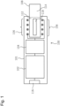
- Fig. 1 is a schematic block diagram of a configuration of an induction heating device 100 according to an embodiment of the present disclosure. It should be reminded that Fig. 1 is not a figure which precisely shows positions, shapes, and dimensions of components, positional relationship between components, and so on.
- the induction heating device 100 comprises a housing 101, an electric power source 102, a circuit 104, and a coil 106.
- the electric power source 102 may be a rechargeable battery such as a lithium-ion secondary battery.
- the circuit 104 is electrically connected to the electric power source 102.
- the circuit 104 is configured to supply, by using the electric power source 102, electric power to components of the induction heating device 100. A tangible configuration of the circuit 104 will be explained later.
- the induction heating device 100 comprises a charging-power-source connector 116 for connecting the induction heating device 100 to a charging power source (this is not shown in the figure) for charging the electric power source 102.
- the charging-power-source connector 116 may be a receptacle for wired charging, a power receiving coil for wireless charging, or a combination thereof.
- the induction heating device 100 is configured to house at least a part of an aerosol forming base substance 108 which comprises a susceptor 110, an aerosol source 112, and a filter 114.
- the aerosol forming base substance 108 may be a smoking article.
- the aerosol source 112 may comprise a volatile compound from which aerosol can be generated by applying heat thereto.
- the aerosol source 112 may be solid or liquid, or may comprise both a solid component and a liquid component.
- the aerosol source 112 may comprise, for example, liquid such as polyhydric alcohol, such as glycerin or propylene glycol, or water, or a combination thereof.
- the aerosol source 112 may comprise a nicotine component.
- the aerosol source 112 may comprise a tobacco material which is formed by condensing granular tobacco. In a different configuration, the aerosol source 112 may comprise a non-tobacco containing material.
- the coil 106 is buried in the housing 101.
- the coil 106 is configured in such a manner that, when the aerosol forming base substance 108 is inserted into the induction heating device 100, it surrounds part of the aerosol forming base substance 108 housed in the induction heating device 100.
- the coil 106 may have a shape of a spirally wound coil.
- the coil 106 is electrically connected to the circuit 104, and used to heat the susceptor 110 by induction heating that will be explained later. By heating the susceptor 110, aerosol is generated from the aerosol source 112. A user can suck the aerosol via the filter 114.
- Fig. 2 shows a configuration of the circuit 104 in detail.
- the circuit 104 comprises a controller 118 which is configured to control components in the induction heating device 100.
- the controller 118 may be configured by using a microcontroller unit (MCU; Micro Controller Unit).
- MCU Microcontroller unit
- the circuit 104 is electrically connected to the electric power source 102 via an electric-power-source connecter, and electrically connected to the coil 106 via a coil connector.
- the circuit 104 comprises a parallel circuit 130 which comprises a path comprising a switch Q 1 arranged between the electric power source 12 and the coil 106 (hereinafter, this path is also referred to as a "first circuit") and a path comprising a switch Q 2 arranged in parallel with the switch Q 1 (hereinafter, this path is also referred to as a "second circuit").
- the first circuit is used for heating the susceptor 110.
- the switch Q 1 may be a metal oxide semiconductor field effect transistor (Metal-Oxide-Semiconductor Field Effect Transistor; MOSFET).
- MOSFET Metal-Oxide-Semiconductor Field Effect Transistor
- the controller 118 controls turning ON/OFF of the switch Q 1 by applying a heating switch signal (HIGH or LOW) to a gate terminal of the switch Q 1 .
- a heating switch signal HIGH or LOW
- the switch Q 1 stays in an ON state when the heating switch signal is LOW.
- the second circuit is used for obtaining values relating to electric resistance or temperature of the susceptor 110.
- the values relating to electric resistance or temperature may be those of impedance, temperature, or the like, for example. Due to resistance R shunt1 , resistance R shunt2 , and so on which will be explained later, the current flowing through the switch Q 2 when the switch Q 2 is in an ON state is small, when it is compared with the current flowing through the switch Q 1 when the switch Q 1 is in an ON state. Thus, a bipolar transistor which requires a low cost and has a small size compared with the cost and the size of a MOSFET, although which is unsuited for the use in large current application, may be used as the switch Q 2 .
- the second circuit may comprise the resistance R shunt1 and the resistance R shunt2 .
- the controller 118 controls turning ON/OFF of the switch Q 2 by applying a monitor switch signal (HIGH or LOW) to a base terminal of the switch Q 2 .
- a monitor switch signal HGH or LOW
- the switch Q 2 stays in an ON state when the monitor switch signal is LOW.
- the monitor 118 can perform switching between a mode for generating aerosol by inductively heating the susceptor 110 and a mode for obtaining values relating to the electric resistance or the temperature of the susceptor 110, by performing switching of the ON state of the switch Q 1 and the ON state of the switch Q 2 .
- the switching of the ON state of the switch Q 1 and the ON state of the switch Q 2 can be performed at arbitrary timing. For example, during a period of time when a use is performing puff, the controller 118 may set the state of the switch Q 1 to the ON state and the state of the switch Q 2 to the OFF state. In the above case, after completion of puff, the controller 118 may set the state of the switch Q 1 to the OFF state and the state of the switch Q 2 to the ON state. In a different configuration, during a period of time when a use is performing puff, the controller 118 may switch the ON state of the switch Q 1 and the ON state of the switch Q 2 at arbitrary timing.
- the circuit 104 comprises an AC generation circuit 132 comprising a switch Q 3 and a capacitor C 1 .
- the switch Q 3 may be a MOSFET.
- the controller 118 controls turning ON/OFF of the switch Q 3 by applying an alternating-current (AC) switch signal (HIGH or LOW) to a gate terminal of the switch Q 3 .
- AC alternating-current
- the switch Q 3 stays in an ON state when the AC switch signal is LOW.
- the AC generation circuit 132 is arranged in a position between the parallel circuit 130 and the coil 106.
- the AC generation circuit 132 may be arranged in a position between the parallel circuit 130 and the electric power source 102.
- the alternating current generated by the AC generation circuit 132 is supplied to an induction heating circuit comprising a capacitor C 2 , the coil connector, and the coil 106.
- Fig. 3 is a figure which conceptually shows relationship between the voltage Vi applied to the gate terminal of the switch Q 1 or the base terminal of the switch Q 2 , the voltage V 2 applied to the gate terminal of the switch Q 3 , the current I DC generated as a result of switching of the switch Q 3 , and the current I AC flowing to the coil 106, when AC current supplied to the coil 106 is generated by the AC generation circuit 132; wherein each of horizontal axes represents time. It should be reminded that, for the purpose of simplification of the figure, the voltage applied to the gate terminal of the switch Q 1 and the voltage applied to the base terminal of the switch Q 2 are represented as Vi by using a single graph.
- the switch Q 1 may be kept to be in an ON state, when the switch Q 3 is switched at a predetermined cycle T.
- the switch Q 2 may be kept to be in an ON state, when the switch Q 3 is switched at the predetermined cycle T. Further, switching of the switch Q 3 at the predetermined cycle T may be continued, when switching between the switch Q 1 and the switch Q 2 is performed.
- the above configuration of the AC generation circuit 132 is a mere example. It should be understood that various kinds of elements, an integrated circuit such as a DC/AC inverter, and so on for generating the AC current I AC can be used as the AC generation circuit 132.
- the frequency f of the AC current I AC is controlled by the switching cycle (i.e., the switching cycle of the AC switch signal) T of the switch Q 3 .
- the switching cycle i.e., the switching cycle of the AC switch signal
- the switch Q 1 is in an ON state, the efficiency of supplying of energy to the susceptor 110 becomes higher, as the above frequency f approaches the resonance frequency f 0 of the RLC series circuit comprising the susceptor 110 (or a circuit comprising the susceptor 110), the coil 106, and the capacitor C 2 .
- the RLC series circuit includes the susceptor 110 in the case that the aerosol forming base substance 108 is being inserted into the housing 101, and the RLC series circuit does not include the susceptor 110 in the case that the aerosol forming base substance 108 is not being inserted into the housing 101.
- the circuit 104 comprises a voltage detecting circuit 134 which comprises a voltage divider circuit comprising R div1 and R div2 .
- the value of the voltage value of the electric power source 102 can be measured by the voltage detecting circuit 134.
- the circuit 104 further comprises a current detecting circuit 136 comprising R sense2 .
- the current detecting circuit 136 may comprise an operational amplifier. In a different configuration, the operational amplifier may be included in the controller 118. The value of current flowing toward the coil 106 can be measured by the current detecting circuit 136.
- the voltage detecting circuit 134 and the current detecting circuit 136 are used for measuring the impedance of the circuit.
- the circuit includes the susceptor 110 in the case that the aerosol forming base substance 108 is being inserted into the housing 101, and the circuit does not include the susceptor 110 in the case that the aerosol forming base substance 108 is not being inserted into the housing 101.
- the measured impedance includes a resistance component of the susceptor 110 in the case that the aerosol forming base substance 108 is being inserted into the housing 101, and the measured impedance includes no resistance component of the susceptor 110 in the case that the aerosol forming base substance 108 is not being inserted into the housing 101.
- the controller 118 obtains a voltage value from the voltage detecting circuit 134 and obtains a current value from the current detecting circuit 136.
- the controller 118 calculates the above impedance based on the above voltage value and the above current value. More specifically, the controller 118 calculates the above impedance by dividing an average value or an effective value of the voltage values by an average value or an effective value of the current values.
- an RLC series circuit is formed by the susceptor 110 and a circuit comprising the resistor R shunt1 and the resistor R shunt2 , the coil 106, and the capacitor C 2 .
- the impedance of the above RLC series circuit can be obtained in the manner explained above.
- the impedance of the susceptor 110 can be calculated by subtracting, from the obtained impedance, a resistance value of a circuit including resistance values of the resistor R shunt1 and the resistor R shunt2 . In the case that the impedance of the susceptor 110 has temperature dependence, the temperature of the susceptor 110 can be estimated based on the calculated impedance.
- the circuit 104 may comprise a remaining quantity measuring integrated circuit (IC) 124.
- the circuit 104 may comprise a resistor R sense1 which is used by the remaining quantity measuring IC 124 for measuring the value of charged/discharged current of the electric power source 102.
- the resistor R sense1 may be connected between an SRN terminal and an SRP terminal of the remaining quantity measuring IC 124.
- the remaining quantity measuring IC 124 may obtain a value relating to the voltage of the electric power source 102 via a BAT terminal.
- the remaining quantity measuring IC 124 is an IC configured to be able to measure the remaining quantity of the electric power source 102.
- the remaining quantity measuring IC 124 may be configured to record information relating to states of deterioration of the electric power source 102 and so on.
- the controller 118 can obtain a value relating to the remaining quantity of the electric power source 102, a value relating to the state of deterioration of the electric power source 102, and so on, that have been stored in the remaining quantity measuring IC 124, at timing that an I 2 C clock signal is transmitted from an SCL terminal of the controller 118 to an SCL terminal of the remaining quantity measuring IC 124, by transmitting an I 2 C data signal from an SDA terminal of the controller 118 to an SDA terminal of the remaining quantity measuring IC 124.
- the remaining quantity measuring IC 124 is configured to update data in a one-second cycle. Accordingly, in the case that the impedance of the above RLC series circuit is calculated by using the voltage value and the current value measured by the remaining quantity measuring IC 124, the impedance is calculated in the one-second cycle that is the fastest speed. Thus, at the fastest rate, the temperature of the susceptor 110 is estimated in the one-second cycle. A cycle such as that explained above is not regarded as a cycle that is sufficiently short for appropriately controlling heating of the susceptor 110. Accordingly, in the present embodiment, it is desirable to prevent the voltage value and the current value measured by the remaining quantity measuring IC 124 from being used in measurement of the impedance of the RLC series circuit.
- the remaining quantity measuring IC 124 is not an indispensable component. However, by using the remaining quantity measuring IC 124, the state of the electric power source 102 can be grasped precisely.
- the induction heating device 100 may comprise a light emitting element 138 such as an LED or the like.
- the circuit 104 may comprise a light-emitting-element driving circuit 126 for driving the light emitting element 138.
- the light emitting element may be used for providing a user with various kinds of information such as the state of the induction heating device 100, and so on.
- the light-emitting-element driving circuit 126 may store information relating to various types of light emission modes of the light emitting element 138.
- the controller 118 can control the light-emitting-element driving circuit 126 to make the light emitting element 138 emit light in a desired mode, by specifying the desired light emission mode by transmitting an I 2 C data signal from an SDA terminal of the controller 118 to an SDA terminal of the light-emitting-element driving circuit 126.
- the circuit 104 may comprise a charging circuit 122.
- the charging circuit 122 may be an IC which is configured in such a manner that it adjusts a voltage (a potential difference between a VBUS terminal and a GND terminal) that is supplied, in response to a charging enable signal that is outputted from the controller 118 and received by a CE terminal, from the charging power source (this is not shown in the figure) via the charging-power-source connector 116 to a voltage that is appropriate for charging of the electric power source 102.
- the adjusted voltage is supplied from a BAT terminal of the charging circuit 122. In this regard, adjusted current may be supplied from the BAT terminal of the charging circuit 122.
- the circuit 104 may further comprise a voltage divider circuit 140.
- a VBUS detection signal is transmitted from a VBUS terminal of the charging circuit 122 to the controller 118 via the voltage divider circuit 140.
- the VBUS detection signal takes a value of a voltage that is obtained by voltage-dividing a voltage supplied from the charging power source by the voltage divider circuit 140, so that the VBUS detection signal becomes a HIGH level. If connection with the charging power source is not made, the VBUS detection signal becomes a LOW level, since connection to the ground via the voltage divider circuit 140 is made.
- the controller 118 can judge the state as a state that charging is started.
- the CE terminal may be that using positive logic or negative logic.
- the circuit 104 may comprise a button 128.
- the button 128 When the button 128 is pressed by a user, connection to the ground via the button 128 is made, so that a button detection signal having a LOW level is transmitted to the controller 118.
- the controller 118 can judge the state as a state that the button has been pressed, and control the circuit 104 to start generation of aerosol.
- the circuit 104 may comprise a voltage adjusting circuit 120.
- the voltage adjusting circuit 120 is configured to generate a voltage V sys (for example, 3 volts), that is supplied to the components in the circuit 104 or the induction heating device 100, by adjusting the voltage V BAT (for example, 3.2-4.2 volts) of the electric power source 102.
- the voltage adjusting circuit 120 may be a linear regulator such as an LDO (low dropout regulator) or the like.
- the voltage V BAT generated by the voltage adjusting circuit 120 may be supplied to a VDD terminal of the controller 118, a VDD terminal of the remaining quantity measuring IC 124, a VDD terminal of the light-emitting-element driving circuit 126, a circuit comprising the button 128, and so on.
- the current detecting circuit 136 may be arranged in a position, in a path between the electric power source 102 and the coil 106, that is close to the coil 106 than a branch point (point A in Fig. 2 ) branching the path to the voltage adjusting circuit 120. According to the above configuration, the current detecting circuit 136 can precisely measure the value of current that is supplied to the coil 106 and does not include current supplied to the voltage adjusting circuit 120. Thus, the impedance, temperature, or the like of the susceptor 110 can be measured or estimated precisely.
- the circuit 104 may be configured in such a manner that the current detecting circuit 136 is not arranged in a position in a path between the charging circuit 122 and the electric power source 102. Specifically, as shown in the figure, the current detecting circuit 136 may be arranged in a position, in the path between the electric power source 102 and the coil 106, that is close to the coil 106 than a branch point (point B in Fig. 2 ) branching the path to the charging circuit 122.
- a branch point point B in Fig. 2
- the circuit 104 may further comprise a switch Q 4 which is switched between an ON state and an OFF state by a ground switch signal transmitted from the controller 118.
- the controller 118 uses at least seven modes, specifically, a SLEEP mode, a CHARGE mode, an ACTIVE mode, a PRE-HEAT mode, an INTERVAL mode, a HEAT mode, and an ERROR mode; and the processes performed by the controller 118 will be explained in relation to the respective modes.
- induction heating of the susceptor 110 performed by the induction heating device 100 is achieved by a process comprising the PRE-HEAT mode, the INTERVAL mode, and the HEAT mode.
- Fig. 4 is a flow chart of an example process 400 performed by the controller 118 when the mode is the SLEEP mode.
- the SLEEP mode may be a mode that reduces the quantity of consumed electric power during the time when the induction heating device 100 is not used.
- S410 represents a step for judging whether a charging power source is being connected to the charging-power-source connector 116. Based on the above-explained VBUS detection signal, the controller 118 can judge that connection with the charging power source has been detected. If it is judged that connection with the charging power source has been detected ("Yes” in S410), the controller 118 changes the mode to the CHARGE mode; and, if not ("No” in S410), the process proceeds to step S420. In a tangible example, in S410, result of judgment will be "Yes” if the VBUS detection signal is in a HIGH level, and result of judgment will be "No” if the VBUS detection signal is in a LOW level.
- S420 represents a step for judging whether predetermined manipulation of the button 128 in the induction heating device 100 is detected. Based on the above-explained button detection signal, the controller 118 can judge that the predetermined manipulation of the button 128 is detected. In this regard, an example of the predetermined manipulation is long pressing or pounding of the button 128. If it is judged that the predetermined manipulation of the button 128 has been detected ("Yes” in S420), the controller 118 changes the mode to the ACTIVE mode; and, if not ("No" in S420), the process returns to the step S410.
- the controller 118 enters the CHARGE mode in response to detection of connection with the charging power source, and enters the ACTIVE mode in response to detection of manipulation of the button. In other words, the controller 118 stays in the SLEEP mode, if none of connection with the charging power source and manipulation of the button is detected.
- Fig. 5 is a flow chart of an example process 500 performed by the controller 118 when the mode is the CHARGE mode.
- the example process 500 may be started in response to an event that the controller 118 enters the CHARGE mode.
- S510 represents a step for performing a process for starting charging of the electric power source 102.
- the process for starting charging of the electric power source 102 may comprise a process for changing the state of the above-explained charging enable signal to an ON state or for starting transmission of the charging enable signal.
- Changing of the state of the above-explained charging enable signal to an ON state refers to changing of the level of the charging enable signal to a level that conforms to the logic of the CE terminal. That is, the above process refers to the process for changing the charging enable signal to have a HIGH level if the CE terminal uses positive logic, and changing the charging enable signal to have a LOW level if the CE terminal uses negative logic.
- S520 represents a step for judging whether detaching of the charging power source from the charging-power-source connector 116 has been detected. Based on the above-explained VBUS detection signal, the controller 118 can detect detaching of the charging power source from the charging-power-source connector 116. If it is judged that detaching of the charging power source has been detected ("Yes” in S520), the process proceeds to step S530; and, if not ("No" in S520), the process returns to the step S520.
- S530 represents a step for performing a process for terminating charging of the electric power source 102.
- the process for terminating charging of the electric power source 102 may comprise a process for changing the state of the above-explained charging enable signal to an OFF state or for stopping transmission of the charging enable signal.
- Changing of the state of the charging enable signal to an OFF state refers to changing of the level of the charging enable signal to a level that does not conform to the logic of the CE terminal. That is, the above process refers to the process for changing the charging enable signal to have a LOW level if the CE terminal uses positive logic, and changing the charging enable signal to have a HIGH level if the CE terminal uses negative logic.
- S540 represents a step for setting, based on the charge level of the electric power source 102 (the quantity of electric power remaining in the electric power source 102), the number of usable sticks, i.e., the aerosol forming base substances 108 (Although it is assumed that the aerosol forming base substance 108 has a stick shape, the shape of the aerosol forming base substance 108 is not limited to the stick shape. Thus, it should be reminded that "the number of usable sticks" can be generalized to "the number of usable articles.”). In the following description, the number of usable sticks will be explained with reference to Fig. 6. Fig. 6 is a pseudo graph used for explaining matters relating to the number of usable sticks.
- the 610 corresponds to a state wherein the electric power source 102 has not been used yet (hereinafter, this state is referred to as an "unused state"), and the area thereof represents the full-charge quantity in the unused state.
- the state that the electric power source 102 has not been used yet may be the state that the number of times of discharging is zero, or equal to or less than a first predetermined number of times of discharging, since the electric power source is manufactured.
- An example of the full-charge quantity of the electric power source 102 in the unused state is approximately 220 mAh.
- 620 corresponds to a state wherein the electric power source 102 has been used in the induction heating device 100, specifically, charging and discharging processes have been performed repeatedly, and the electric power source 102 has been deteriorated to a certain extent (hereinafter, this state is referred to as a "deteriorated state"), and the area thereof represents the full-charge quantity in the deteriorated state.
- the full-charge quantity of the electric power source 102 in the unused state is larger than the full-charge quantity of the electric power source 102 in the deteriorated state.
- 630 corresponds to the quantity of electric power (energy) required for consuming a single aerosol forming base substance 108, and the area represent the corresponding quantity of electric power.
- the four areas of four 630s in Fig. 6 are the same, and the quantities of electric power corresponding to the areas are also approximately the same.
- an example of the quantity 630 of electric power required for consuming a single aerosol forming base substance 108 is approximately 70 mAh.
- a single aerosol forming base substance 108 has been consumed, when a predetermined number of times of suction actions are completed or heating is performed for a predetermined period of time.
- Each of 640 and 650 corresponds to a charge level of the electric power source 102 after consuming two aerosol forming base substances 108 (hereinafter, this will be referred to as the "surplus power quantity"), and the area thereof represents the corresponding quantity of electric power.
- the surplus power quantity 640 in the unused state is larger than the surplus power quantity 650 in the deteriorated state.
- 660 represents the output voltage of the electric power source 102 in the full-charge state, and an example thereof is approximately 3.64 V.
- the voltage of the electric power source 102 in the full-charge state is basically constant regardless of deterioration, i.e., SOH (State Of Health), of the electric power source 102.
- 670 represents a discharge cut-off voltage of the electric power source 102, and an example thereof is approximately 2.40 V.
- the discharge cut-off voltage of the electric power source 102 is basically constant regardless of deterioration, i.e., SOH, of the electric power source 102.
- the full-charge quantity of the electric power source 102 decreases after the electric power source 102 is used, specifically, charging and discharging processes are preformed repeatedly; and the surplus power quantity after consumption of a predetermined number (that is 2 in Fig. 6 ) of aerosol forming base substances 108 in the deteriorated state (650) becomes smaller than that in the unused state (640).
- the controller 118 set, by taking deterioration of the electric power source 102 into consideration, the number of usable sticks, for preventing the electric power source 102 from being used until the voltage reaches the discharge cut-off voltage 670 or reaches a voltage close thereto, in other words, until the charge level of the electric power source 102 becomes zero or becomes a charge level close thereto.
- n denotes the number of usable sticks
- e denotes the charge level of the electric power source (the unit thereof is mAh, for example)
- S denotes a parameter for adding a margin to the surplus power quantity 650 of the electric power source 102 in the deteriorated state (the unit thereof is mAh, for example)
- C denotes the quantity of electric power required for consuming a single aerosol forming base substance 108
- int() denotes a function for rounding down decimal places in the parentheses ().
- e is a variable, and can be obtained by the controller 118 by performing communication with the remaining quantity measuring IC 124.
- S and C are constants, and may be experimentally obtained in advance and preliminarily stored in a memory (which is not shown in the figure) in the controller 118.
- S may be the value of the surplus power quantity 650 that is obtained after a second predetermined number of times of discharging (>> the first predetermined number of times of discharging) of the electric power source 102 is performed experimentally, that is, when conceivable deterioration is observed, or the value obtained by adding + ⁇ to the above surplus power quantity.
- the controller 118 may judge that deterioration of the electric power source 102 has progressed considerably, in the case that it is judged that the SOH obtained by performing communication with the remaining quantity measuring IC 124 has reached a predetermined value; and may stop the charging/discharging process of the electric power source 102. That is, the deteriorated state at the time when calculating S refers to the state wherein, although the SOH has not yet reached the predetermined value, the state of deterioration has progressed further compared with that in the unused state.
- the controller 118 enters the ACTIVE mode after the step S540.
- the controller 118 judges, in the step S520, whether detaching of the charging power source from the charging-power-source connector 116 has been detected.
- completion of charging of the electric power supply 102 may be judged by the charging circuit 122, and judging as to whether result of the above judgment has been received by the controller 118 via I2C communication or the like may be performed.
- Fig. 7 is a flow chart of an example process (hereinafter, this will be referred to as the "main process") 700 that is mainly performed by the controller 118 when the mode is the ACTIVE mode.
- the main process 700 can be started in response to transition of the mode of the controller 118 to the ACTIVE mode.
- S705 represents a step for activating a first timer.
- the value of the first timer is increased or decreased from an initial value with time.
- the first timer may be stopped when the controller 118 changes the present mode to a different mode. The above matter also applies to the second timer and the third timer which will be explained later.
- S710 represents a step for notifying a user of a charge level of the electric power source 102.
- Notifying of the charge can be realized by the process that the controller 118 communicates with the light-emitting-element driving circuit 126, based on information of the electric power source 102 obtained by communication with the remaining quantity measuring IC 124, and makes the light emitting element 138 emit light in a predetermined mode.
- the above matter also applies to other notification that will be explained later. It is preferable that notifying of the charge level be performed temporarily.
- S715 represents a step for activating a different process (hereinafter, this will be referred to as the "sub-process") for executing it in parallel with the main process 700.
- the sub-process that is activated in this step will be explained later.
- executing of the sub-process may be stopped when the controller 118 changes the present mode to a different mode.
- the above matter also applies to other sub-processes that will be explained later.
- S720 represents a step for judging, based on the value of the first timer, whether predetermined time has elapsed. If it is judged that the predetermined time has elapsed ("Yes" in S720), the controller 118 enters the SLEEP mode, and, if not ("No" in S720), the process proceeds to step S725.
- S725 represents a step for performing control for supplying AC electric power, that is not used for heating, to the above-explained RLC series circuit, i.e., the circuit for inductively heating the susceptor 110 which is at least a part of the aerosol forming base substance 108, and measuring the impedance of the RLC series circuit.
- the AC electric power that is not used for heating may be generated by setting the state of the switch Q 1 to an OFF state, setting the state of the switch Q 2 to an ON state, and, thereafter, performing switching of the switch Q 3 .
- the average value or the effective value of the energy supplied, by supplying the AC electric power that is not used for heating, to the RLC series circuit is smaller than the average value or the effective value of the energy supplied, by supplying the AC electric power that is used for heating that will be explained later, to the RLC series circuit.
- the AC electric power that is not used for heating has a resonance frequency f 0 of the RLC series circuit.
- the only purpose for the supplying of the AC electric power that is not used for heating is to measure the impedance of the RLC series circuit.
- supplying of the AC electric power that is not used for heating may be stopped without delay, after the data for measuring the impedance of the RLC series circuit (for example, the effective value of the voltage V RMS and the effective value of the current I RMS measured by the voltage detecting circuit 134 and the current detecting circuit 136, respectively) is obtained.
- the above supplying of the AC electric power that is not used for heating may be continued until a predetermined point in time, for example, until the controller 118 enters a different mode.
- Stopping of supplying of the AC electric power that is not used for heating may be realized by either one or both a process for setting the state of the switch Q 2 to an OFF state and a process for stopping switching of the switch Q 3 and setting the state of the switch Q 3 to an OFF state. It should be reminded that, at the time of the step S725, the switch Q 1 may originally be allowed to keep its OFF state.
- S730 represents a step for judging whether the measured impedance is abnormal.
- the controller 118 can judge that the impedance measured in the step 725 is abnormal, in the case that the measured impedance is not that within a range of impedance that includes a measurement error defined based on the impedance that is measured when a genuine aerosol forming base substance 108 is appropriately inserted into the induction heating device 100. If it is judged that the impedance is abnormal ("Yes" in S730), the process proceeds to S735, and, if not ("No" in S730), the process proceeds to S745.
- S735 represents a step for performing a predetermined fail-safe action.
- the predetermined fail-safe action may comprise action for setting the states of all of the switches Q 1 , Q 2 , and Q 3 to OFF states.
- S740 represents a step for providing a user with predetermined error notification. After the step S740, the controller 118 enters the ERROR mode for performing a predetermined error handling process. In this explanation, explanation with respect to tangible processes in the ERROR mode will be omitted.
- S745 represents a step for judging whether a susceptor 110 is detected based on the impedance measured in the step S725.
- detecting of a susceptor 110 can be regarded as detecting of an aerosol forming base substance 108 including the susceptor 110. Explanation with respect to detecting of the susceptor 110 based on the impedance will be provided later.
- S750 represents a step for judging whether the number of usable sticks is equal to or greater than one. If the number of usable sticks is equal to or greater than one ("Yes” in S750), the controller 118 enters the PRE-HEAT mode, and, if not ("No" in S750), the process proceeds to step S755.
- S755 represents a step for providing a user with predetermined low-remaining-quantity notification that shows a state that the remaining quantity of electric power in the electric power source 102 is low.
- the controller 118 enters the SLEEP mode.
- induction heating of the aerosol forming base substance 108 is performed.
- main process 700 automatic induction heating of the aerosol forming base substance 108, after insertion of the aerosol forming base substance 108 into the housing 101, can be realized.
- Fig. 8 is a flow chart of an example first sub-process 800 that is activated in the step S715 in the main process 700 in the ACTIVE mode.
- S810 represents a step for judging whether predetermined manipulation of the button 128 has been detected.
- an example of the predetermined manipulation in the step S810 is short pressing of the button 128. If it is judged that the predetermined manipulation of the button 128 has been detected ("Yes” in S810), the process proceeds to S820, and, if not ("No" in S810), the process returns to the step S810.
- S820 represents a step for resetting the first timer to reset its value to the initial value.
- the value of the first timer may be changed to make it approach the initial value, or the predetermined time in the step S720 may be separated away from the value of the first timer.
- S830 represents a step for notifying a user of the charge level of the electric power source 102. After the step S830, the process returns to the step S810.
- the controller 118 enters the SLEEP mode when a predetermined period has elapsed since it has entered the ACTIVE mode; and, according to the sub-process 800, it becomes possible to notify a user of the charge level of the electric power source 102 again, and postpone transition to the SLEEP mode, by performing predetermined manipulation of the button 128.
- Fig. 9 is a flow chart of an example second sub-process 900 that is activated in the step S715 in the main process 700 in the ACTIVE mode.
- S910 represents a step for judging whether connection of a charging power source to the charging-power-source connector 116 has been detected. If it is judged that connection of a charging power source has been detected ("Yes” in S910), the controller 118 enters the CHARGE mode, and, if not ("No" in S910), the process returns to the step S910. Similar to the step S410, the controller 118 can judge that connection of a charging power source has been detected, based on the above-explained VBUS detection signal. In this regard, when performing transition to the CHARGE mode, it is preferable that the controller 118 set the states of all of the switches Q 1 , Q 2 , and Q 3 to OFF states.
- the controller 118 automatically enters the CHARGE mode in response to connection of the charging power source.
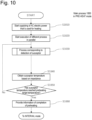
- Fig. 10 is a flow chart of an example process (main process) 1000 that is mainly performed by the controller 118 when the mode is the PRE-HEAT mode.
- the main process 1000 may be started in response to transition of the mode of the controller 118 to the PRE-HEAT mode.
- S1010 represents a step for performing control for starting supplying of AC electric power, that is used for heating, to the RLC series circuit.
- the AC electric power for heating is that generated by setting the state of the switch Q 1 to an ON state, setting the state of the switch Q 2 to an OFF state, and, thereafter, performing switching of the switch Q 3 .
- the average value or the effective value of the energy supplied, by supplying the AC electric power for heating, to the RLC series circuit is larger than the average value or the effective value of the energy supplied, by supplying the above AC electric power that is not used for heating, to the RLC series circuit.
- S1020 represents a step for activating a different process (sub-process) for executing it in parallel with the main process 1000. Explanation of the sub-process activated in this step will be provided later.
- S1030 represents a step for executing processes that are executed in response to detection of the susceptor 110. Explanation of the step will be provided later.
- the step comprises, at least, a step for measuring the impedance of the RLC series circuit.
- S1040 represents a step for obtaining temperature of at least a part of the susceptor 110 or the aerosol forming base substance 108 (hereinafter, this will be referred to as "susceptor-temperature" for convenience) from the impedance measured in the step S1030. Explanation with respect to obtaining of the susceptor-temperature based on the impedance will be provided later.
- the step S1040 may be omitted, by using, in place of preheating target temperature, preheating target impedance corresponding to the preheating target temperature in step S1050 that will be explained later. In the above case, the impedance and the preheating target impedance are compared with each other in the step S1050.
- S1050 represents a step for judging whether the obtained susceptor-temperature has reached a predetermined preheating target temperature. If it is judged that the susceptor-temperature has reached the preheating target temperature ("Yes” in S1050), the process proceeds to S1060, and, if not ("No” in S1050), the process returns to the step S1030. In this regard, in the case that predetermined time has elapsed since a start of the PRE-HEAT mode, it is possible to regard that the preheating is completed, and draw "Yes" in judgment in the step S1050.
- S1060 represents a step for notifying a user of completion of preheating of the aerosol forming base substance 108.
- the above notification may be provided by the LED 138, or may be provided by a vibrating motor, a display, or the like which is not shown in the figure.
- the controller 118 enters the INTERVAL mode.
- preheating of the aerosol forming base substance 108 can be realized.
- Fig. 11 is a flow chart of an example process (main process) 1100 that is mainly performed by the controller 118 when the mode is the INTERVAL mode.
- the main process 1100 may be started in response to transition of the mode of the controller 118 to the INTERVAL mode.
- S1110 represents a step for performing control for stopping supplying of the AC electric power, that is used for heating, to the RLC series circuit. Stopping of supplying of the AC electric power, that is used for heating, may be realized by either one or both a process for setting the state of the switch Q 1 to an OFF state and a process for stopping switching of the switch Q 3 and setting the state of the switch Q 3 to an OFF state. It should be reminded that, at the time of the step S1110, the switch Q 2 may originally be allowed to keep its OFF state.
- S1120 represents a step for activating a different process (sub-process) for executing it in parallel with the main process 1100. Explanation of the sub-process activated in this step will be provided later.
- S1130 represents a step for performing control for supplying AC electric power, that is not used for heating, to the RLC series circuit, and measuring the impedance of the RLC series circuit. This step may be that similar to the step S725 in the main process 700 in the ACTIVE mode.
- step S1140 represents a step for obtaining susceptor-temperature from the measured impedance.
- the step S1140 may be omitted, by using, in place of cooling target temperature, cooling target impedance corresponding to the cooling target temperature in step S1150 that will be explained later.
- the impedance and the cooling target impedance are compared with each other in the step S1150.
- S1150 represents a step for judging whether the obtained susceptor-temperature has reached a predetermined cooling target temperature. If it is judged that the susceptor-temperature has reached the cooling target temperature ("Yes" in S1 150), the controller 118 enters the HEAT mode, and, if not ("No" in S1150), the process returns to the step S1130. In this regard, in the case that predetermined time has elapsed since a start of the INTERVAL mode, it is possible to regard that the cooling is completed, and draw "Yes" in judgment in the step S1150.
- the susceptor In the PRE-HEAT mode, the susceptor is rapidly heated to realize quick supplying of aerosol. On the other hand, in such rapid heating, there is a risk that an excessive quantity of aerosol is generated.
- the quantity of generated aerosol can be stabilized during the period from the point in time when the PRE-HEAT mode is completed to the point in time when the HEAT mode is completed.
- the main process 1100 for stabilizing generation of aerosol, it is possible to cool the preheated aerosol forming base substance 108 before the HEAT mode.
- Fig. 12 is a flow chart of an example process (main process) 1200 that is mainly performed by the controller 118 when the mode is the HEAT mode.
- the main process 1200 may be started in response to transition of the mode of the controller 118 to the HEAT mode.
- S1205 represents a step for activating a second timer.
- S1210 represents a step for activating a different process (sub-process) for executing it in parallel with the main process 1200. Explanation of the sub-process activated in this step will be provided later.
- S1215 represents a step for performing control for starting supplying of AC electric power, that is used for heating, to the RLC series circuit.
- S1220 represents a step for executing processes that are executed in response to detection of the susceptor 110. Although explanation of the step will be provided later, the step comprises, at least, a step for measuring the impedance of the RLC series circuit.
- step S1225 represents a step for obtaining the susceptor-temperature from the impedance measured in the step S1220.
- the step S1225 may be omitted, by using, in place of heating target temperature, heating target impedance corresponding to the heating target temperature in step S1230 that will be explained later.
- the impedance and the heating target impedance are compared with each other in the step S1230.
- S1230 represents a step for judging whether the obtained susceptor-temperature is equal to or higher than a predetermined heating target temperature. If it is judged that the susceptor-temperature is equal to or higher than the heating target temperature ("Yes" in S1230), the process proceeds to S1235, and, if not ("No" in S1230), the process proceeds to S1240.
- S1235 represents a step for performing control for stopping supplying of the AC electric power for heating to the RLC series circuit, and performing action of waiting for a predetermined period of time. Objects intended to be achieved by the step is to temporarily stop supplying of the AC electric power for heating to the RLC series circuit, and lower the susceptor-temperature that has been raised to temperature higher than the heating target temperature.
- S1240 represents a step for judging whether a predetermined condition for terminating heating is satisfied.
- the predetermined conditions for terminating heating may be a condition that it is determined based on the value of the second timer that a predetermined time has elapsed, a condition that a predetermined number of times of suction actions are performed by using an aerosol forming base substance 108 which is presently used, or an OR condition of these conditions. Explanation with respect to a method for detecting suction action will be provided later. If it is judged that the condition for terminating heating is satisfied ("Yes" in S1240), the process proceeds to step S1245, and, if not ("No" in S1240), the process returns to the step S1220.
- S1245 represents a step for decrementing the number of usable sticks by 1. After the step S1245, the controller 118 enters the SLEEP mode.
- the susceptor-temperature can be maintained at predetermined temperature for generating aerosol in a desired mode.
- Fig. 13A is a flow chart of an example process 1300A that is performed in response to detection of a susceptor 110.
- S1305 represents a step for measuring the impedance of the RLC series circuit. It should be reminded that supplying of AC electric power for heating to the RLC series circuit has been started before the step S1305.
- S1310 represents a step for judging, based on the measured impedance, whether a susceptor 110 has been detected. If a susceptor 110 has been detected based on the measured impedance ("Yes" in S1310), the example process 1300A is terminated, and the process returns to the main process 1000 or the main process 1200; and, if not ("No" in S1310), the process proceeds to S1315.
- S1315 represents a step for stopping supplying of AC electric power for heating to the RLC series circuit.
- S1320 represents a step for decrementing the number of usable sticks by 1. After the step S1320, the controller 118 enters the ACTIVE mode.
- induction heating can be stopped in the case that the aerosol forming base substance 108 is removed during induction heating, or the like.
- safety of the induction heating device 100 can be improved, and consumption of electric power stored in the electric power source 102 can be lowered.
- the controller 118 decrements the number of usable sticks by 1 when the aerosol forming base substance 108 is removed.
- progress of deterioration of the electric power source 102 can also be suppressed.
- Fig. 13B is a flow chart of a different example process 1300B that is performed in response to detection of a susceptor 110. Since the example process 1300B shares some steps with the example process 1300A, differences between them will be explained in the following description.
- step S1325 the process proceeds to step S1325 after the step S1315.
- S1325 represents a step for providing a user with predetermined error notification.
- the predetermined error notification is that corresponding to an event that detection of the susceptor 110 during induction heating was not performed successfully due to erroneous removal of the aerosol forming base substance 108, or the like.
- the predetermined error notification may be provided by using LED 138 or the like.
- S1330 represents a step for activating the third timer.
- S1335 represents a step for performing control for supplying AC electric power, that is not used for heating, to the RLC series circuit, and measuring the impedance of the RLC series circuit.
- the step may be that similar to the step S725 in the main process 700 in the ACTIVE mode.
- S1340 represents a step for judging, based on the measured impedance, whether the susceptor 110 has been detected. If the susceptor 110 has been detected based on the measured impedance ("Yes” in S1340), the process proceeds to step S1350, and, if not ("No" in S1340), the process proceeds to step S1345.
- S1350 represents a step for restarting supplying of AC electric power for heating to the RLC series circuit, that was stopped in the step S1315.
- S1345 represents a step for judging, based on the value of the third timer, whether a predetermined period of time has elapsed. If it is judged that the predetermined time has elapsed ("Yes” in S1345), the process proceeds to S1320, and, if not ("No" in S1345), the process returns to the step S1335.
- Fig. 14 is a graph representing change in the susceptor-temperature.
- the vertical axis of the graph corresponds to temperature, and the horizontal axis corresponds to time.
- 1410 represents the predetermined preheating target temperature that has been explained in relation to the main process 700 in the PRE-HEAT mode.
- 1415 represents the predetermined cooling target temperature that has been explained in relation to the main process 1100 in the INTERVAL mode.
- 1420 represents the predetermined heating target temperature that has been explained in relation to the main process 1200 in the HEAT mode. Although explanation will be provided later, the HEAT mode comprises a heating profile that comprises plural phases to which different degrees of heating target temperature are applied, respectively. In more detail, 1420 represents heating target temperature for the first phase in the heating profile in the HEAT mode.
- the period of the PRE-HEAT mode represents the period of the PRE-HEAT mode. That is, the period of the PRE-HEAT mode ends roughly when the susceptor-temperature has reached the predetermined preheating target temperature 1410.
- the 1435 represents the period of the INTERVAL mode. That is, the period of the INTERVAL mode starts roughly when the susceptor-temperature has reached the preheating target temperature 1410, and ends roughly when the susceptor-temperature has reached the cooling target temperature 1415.
- 1440 represents the period of the HEAT mode. That is, the period of the HEAT mode starts roughly when the susceptor-temperature has reached the cooling target temperature 1415, and ends at a point in time 1445. 1445 represents the point in time when a condition for terminating heating is satisfied (the step S1240 in the main process 1200).
- 1450 represents a point in time when it has become unable to detect the susceptor 110, that is, the point in time when judgment such that the susceptor 110 has been detected based on the impedance could not be made in the step S1310 in the example process 1300B ("No" in S1310).
- 1455 represents a point in time when it has become able to detect the susceptor 110 again, that is, the point in time when judgment such that the susceptor 110 could be detected based on the impedance could be made in the step S1340 in the example process 1300B ("Yes" in S1340).
- 1460 represents a period during that the susceptor 110 could not be detected.
- induction heating is controlled in such a manner that it follows the heating profile in which at least the heating target temperature according to elapsed time has been defined, and, at the same time, the period of time between the step S1315 for stopping the process for induction heating and the step S1350 for restarting the process for induction heating is considered as elapsed time.
- a part of the heating profile, that corresponds to 1460 during that the susceptor 110 could not be detected, can be skipped.
- Fig. 13C is a flow chart of a different example process 1300C that is performed in response to detection of a susceptor 110. Since the example process 1300C shares some steps with the example process 1300A or 1300B, differences between them will be explained in the following description.
- S1355 represents a step for detecting, based on the detected impedance, a susceptor 110.
- the step is similar to the step S1310; however, it is different in the point that the process proceeds to step S1325, if judgment such that the susceptor 110 could be detected could not be made ("No" in S1355).
- step S1360 the process proceeds to step S1360 after the step S1330.
- step S1360 represents a step for measuring the impedance of the RLC series circuit.
- the step S1360 is similar to the step S1335; however, in the step S1360, it is not required to perform control for supplying AC electric power, that is not used for heating, to the RLC series circuit. This is because, at the time of the step S1360, supplying of AC electric power, that is used for heating, to the RLC series circuit has not been stopped.
- S1365 represents a step for judging, based on the measured impedance, whether the susceptor 110 has been detected.
- the step is similar to the step S1340; however, it is different in the point that, if it is judged based on the impedance that the susceptor 110 has been detected ("Yes” in S1365), the process returns to the step S1305, and, if not ("No" in S1365), the process proceeds to step S1370.
- S1370 represents a step for judging, based on the value of the third timer, whether predetermined period of time has elapsed.
- the step is similar to the step S1345; however, it is different in the point that, if it is judged that the predetermined time has elapsed ("Yes" in S1370), the process proceeds to S1315, and, if not ("No" in S1370), the process returns to the step S1360.
- 1450 represents a point in time when it has become unable to detect the susceptor 110, i.e., the point in time when it has become unable to judge based on the impedance that the susceptor 110 has been detected, in the step S1355 in the example process 1300C ("No" in the step S1355).
- 1455 represents a point in time when it has become able to detect the susceptor 110 again, i.e., the point in time when it has become able to judge based on the impedance that the susceptor 110 has been detected, in the step S1365 in the example process 1300C ("Yes" in the step S1365).
- the HEAT mode comprises a heating profile which comprises plural phases to which different degrees of heating target temperature are applied. Further, it is possible to include, in the process of the HEAT mode, a process for changing the heating target temperature at one or more timings (for example, step S2115 in Fig. 21 that will be explained later). Further, according to the example process 1300C, the period 1460, during that the susceptor 110 could not be detected, will not affect the one or more timings. This is because the example process 1300C does not comprise the step S1315 and the step S1350 in the example process 1300B. That is, according to the example process 1300C, it is possible to prevent the period 1460, during that the susceptor 110 could not be detected, from affecting the overall length of the heating profile.
- Fig. 13D is a flow chart of a further different example process 1300D that is performed in response to detection of a susceptor 110.
- step S1375 represents a step similar to the step S1310; however, it is different in the point that the process proceeds to step S1385, if judgment such that the susceptor 110 could be detected based on the impedance is made.
- step S1380 the process proceeds to step S1380 after the step S1325.
- S1380 represents a step for stopping the second timer that has been activated, and activating the third timer. By stopping the second timer, incrementing of the value of the second timer over time is prevented. In other words, progress of the process according to the heat profile is interrupted.
- S1385 represents a step for judging whether the second timer has been stopped.
- the step may be a step for judging whether execution of the step S1380 has been completed. If it is judged that the second timer has been stopped ("Yes” in S1385), the process proceeds to step S1390, and, if not ("No" in S 1385), execution of the example process 1300D is terminated, and the process returns to the main process 1000 or the main process 1200.
- S1390 represents a step for restarting the stopped second timer.
- the value of the second timer is incremented again over time, from the value at the time when the second timer is stopped. In other words, progress of the process according to the heat profile is restarted.
- the example process 1300D will be explained further, with reference to Fig. 14 .
- differences from the above explanation relating to the example process 1300B will be explained.
- induction heating is controlled in such a manner that it follows the heating profile in which at least the heating target temperature according to elapsed time has been defined, and, at the same time, the period of time between the step S1315 for stopping the process for induction heating and the step S1350 for restarting the process for induction heating is not considered as elapsed time.
- progress of the process according to the heat profile can be interrupted.
- Fig. 13E is a flow chart of a still further different example process 1300E that is performed in response to detection of a susceptor 110. Since the example process 1300E shares some steps with the example process 1300A, 1300B, 1300C, or 1300D, differences between them will be explained in the following description.
- step S1392 represents a step similar to the step S1310; however, it is different in the point that the process proceeds to step S1394, if judgment such that the susceptor 110 could be detected based on the impedance is made.
- S1394 represents a step for judging whether the third timer has been activated.
- the step may be a step for judging whether execution of the step S1330 has been completed. If it is judged that the third timer has been activated ("Yes” in S1394), the process proceeds to step S1396, and, if not ("No" in S 1394), execution of the example process 1300E is terminated, and the process returns to the main process 1000 or the main process 1200.
- the predetermined process may be a process for extending one of the plural phases included in the HEAT mode, by the value of the third timer, that is, by the length of the period during that the susceptor 110 could not be detected.
- the predetermined process may be a process for delaying at least one of the one or more timings at when the heating target temperature is changed, by the length of the period during that the susceptor 110 could not be detected. The above may be realized, for example, by delaying the timing at when judgment to change it is made in step S2105 in Fig. 21 that will be explained later.
- a phase may be extended and/or a timing at when the heating target temperature is changed may be delayed, by a value that is obtained by applying calculation, such as addition or subtraction of a predetermined value to the length of the period during that the susceptor 110 could not be detected or the like, or by a value independent of the length of the period during that the susceptor 110 could not be detected.
- timing to change heating target temperature can be delayed, based on the period 1460 from the step S1392 corresponding to a point in time when it has become unable to detect the aerosol forming base substance to the step S1365 corresponding to a point in time when the aerosol forming base substance has been detected again, so that a phase of the heating profile can be supplemented or extended. That is, according to the example process 1300E, the length of the heating profile can be extended based on the period 1460 during that the susceptor 110 could not be detected.
- Fig. 15 is a flow chart of an example first sub-process 1500 that is activated in the step S1020 in the main process 1000 in the PRE-HEAT mode, the step S1120 in the main process 1100 in the INTERVAL mode, or the step S1210 in the main process 1200 in the HEAT mode.
- S1510 represents a step for judging whether predetermined manipulation of the button 128 has been detected.
- the predetermined manipulation may be that similar to or different from the predetermined manipulation in the step S420 or S810.
- an example of the predetermined manipulation in the step S1510 is long pressing or pounding of the button 128. If it is judged that the predetermined manipulation of the button 128 is detected ("Yes” in S1510), the process proceeds to S1520, and, if not ("No" in S1510), the process returns to the step S1510.
- the AC electric power may be AC electric power that is used for heating; and, in the case that the first sub-process 1500 is activated in the step S1120, the AC electric power may be AC electric power that is not used for heating.
- S1530 represents a step for decrementing the number of usable sticks by 1.
- the number of usable sticks is decremented by 1, when supplying of AC electric power is stopped by manipulation performed by a user.
- Fig. 16 is a flow chart of an example second sub-process 1600 that is activated in the step S1020 in the main process 1000 in the PRE-HEAT mode, the step S1120 in the main process 1100 in the INTERVAL mode, or the step S1210 in the main process 1200 in the HEAT mode.
- S1610 represents a step for measuring discharge current.
- the discharge current may be measured by the current detecting circuit 136.
- S1620 represents a step for judging whether the measured discharge current is excessively large. If it is judged that the measured discharge current is excessively large ("Yes” in S1620), the process proceeds to S1630, and, if not ("No" in S1620), the process returns to the step S1610.
- S1630 represents a step for executing a predetermined fail safe action.
- S1640 represents a step for providing a user with predetermined error notification.
- the predetermined error notification is that corresponding to an event that the discharge current is excessively large.
- the controller enters the ERROR mode.
- the error notification may be provided by using LED 138.
- Fig. 17 is a figure used for explaining a principle of detection, based on impedance, of the susceptor 110 which is at least a part of the aerosol forming base substance 108, and a principle of acquisition, based on impedance, of temperature of the susceptor 110 which is at least a part of the aerosol forming base substance 108.
- 1710 denotes an equivalent circuit of the RLC series circuit when the aerosol forming base substance 108 is not inserted into the induction heating device 100.
- L denotes a value of inductance of the RLC series circuit. Precisely, L is a value obtained by combining inductance components of plural elements included in the RLC series circuit; however, it may be possible to consider the value as that equal to the value of inductance of the coil 106.
- C 2 denotes a value of capacitance of the RLC series circuit. Precisely, C 2 is a value obtained by combining capacitance components of plural elements included in the RLC series circuit; however, it may be possible to consider the value as that equal to the value of capacitance of the capacitor C 2 .
- R Circuit denotes a resistance value of the RLC series circuit.
- R Circuit is a value obtained by combining resistance components of plural elements included in the RLC series circuit.
- L, C 2 , and R Circuit may be obtained from specification sheets of the electronic elements in advance, or measured experimentally in advance, and stored in a memory (which is not shown in the figure) in the controller 118 in advance.
- the impedance Z 0 of the RLC series circuit in the case that the aerosol forming base substance 108 is not inserted into the induction heating device 100, can be calculated by using the following formula.
- Z 0 R circuit 2 + ⁇ L ⁇ 1 ⁇ C 2 2
- 1720 denotes an equivalent circuit of the RLC series circuit when the aerosol forming base substance 108 is being inserted into the induction heating device 100.
- a point that 1720 is different from 1710 is that a resistance component (R susceptor ), that is based on the susceptor 110 which is at least a part of the aerosol forming base substance 108, exists therein.
- the impedance Z 1 of the RLC series circuit in the case that the aerosol forming base substance 108 is being inserted into the induction heating device 100, can be calculated by using the following formula.
- Z 1 R circuit + R susceptor 2 + ⁇ L ⁇ 1 ⁇ C 2 2
- the impedance of the RLC series circuit when the aerosol forming base substance 108 is being inserted into the induction heating device 100 is larger than that when the aerosol forming base substance 108 is not being inserted into the induction heating device 100.
- the impedance Z 0 when the aerosol forming base substance 108 is not being inserted into the induction heating device 100 and the impedance Z 1 when the aerosol forming base substance 108 is being inserted into the induction heating device 100 are obtained experimentally in advance, and a threshold value that is set to a value between the above impedance values is stored in a memory (which is not shown in the figure) in the controller 118 in advance.
- the controller 118 can calculate, as shown below, the impedance Z of the RLC series circuit, based on the effective value of the voltage V RMS and the effective value of the current I RMS measured by the voltage detecting circuit 134 and the current detecting circuit 136, respectively.
- Z V RMS I RMS
- Fig. 18 shows equivalent circuits of the RLC series circuit, wherein each equivalent circuit is that in the case that AC electric power is supplied at a resonance frequency f 0 of the RLC series circuit.
- 1810 and 1820 represent equivalent circuits of the RLC series circuit in the cases that the aerosol forming base substance 108 is not being inserted and is being inserted into the induction heating device 100, respectively.
- R susceptor that is the value of the resistance component that is based on the susceptor 110 which is at least a part of the aerosol forming base substance 108, when the aerosol forming base substance 108 is being inserted into the induction heating device 100 and the resonance frequency f 0 is being applied, can be calculated by using the following formula.
- R susceptor Z ⁇ R circuit
- the resonance frequency f 0 of the RLC series circuit in either or both of the time when detecting the susceptor 110 and the time when obtaining susceptor-temperature based on the impedance, it is advantageous to use the resonance frequency f 0 of the RLC series circuit in the point that the use thereof makes calculation easier. It is of course advantageous to use the resonance frequency f 0 of the RLC series circuit in the point that the use thereof realizes highly efficient and high-speed supplying of electric power stored in the electric power source 102 to the susceptor 110.
- the induction heating device 100 can heat the aerosol forming base substance 108 more appropriately, by changing the switching frequency of the AC generation circuit 132 in the PRE-HEAT mode, the INTERVAL mode, and the HEAT mode comprising plural phases.
- Fig. 19 is a figure showing graphs (a), (b), and (c) which represent change in the temperature of the susceptor 110, the switching frequency of the AC generation circuit 132, and the impedance of the circuit 104, respectively, in the induction heating device 100 according to the present example.
- an arrow 1430 represents the period of time of the PRE-HEAT mode
- an arrow 1435 represents the period of time of the INTERVAL mode
- an arrow 1440 represents the period of time of the HEAT mode.
- the graph drawn by using a solid line represents temperature of the susceptor 110
- the graph drawn by using a broken line represents target temperature in each period (the preheating target temperature, the cooling target temperature, and the heating target temperature).
- Fig. 19 shows ideal behavior, so that it is shown in such a manner that the event that the temperature of the susceptor 110 (or the susceptor-temperature) reaches the heating target temperature and the event that a phase is switched to the other occur concurrently. That is, if the example process shown in Fig. 21 , that will be explained later, is used as an example, the behavior shown in Fig. 19 corresponds to the case that the timing to change the switching frequency of the switch Q 3 and the timing when the temperature of the susceptor 110 has reached the heating target temperature for the first time coincide with each other.
- the behavior that comprises lowering of the temperature by temporarily stopping AC electric power for heating after the temperature has reached heating target temperature and raising of the lowered temperature again, is repeated. Accordingly, in general, the event that the temperature of the susceptor 110 reaches the heating target temperature and the event that a phase is switched to the other do not occur concurrently.
- the above matter also applies to Figs. 20 and 22 .
- the switching frequency of the switch Q 3 in the AC generation circuit 132 is the resonance frequency f 0 during the period 1430 of the PRE-HEAT mode and the period 1435 of the INTERVAL mode, and is constant in the above periods.
- the switching frequency of the switch Q 3 is controlled in such a manner that it rises in a stepwise manner as the respective phases proceed (The timings to raise the switching frequency of the switch Q 3 are scheduled in advance. The above matter also applies to the tangible example 2 that will be explained later). Further, the impedance of the circuit 104 changes as the switching frequency of the switch Q 3 changes.
- the impedance of the circuit 104 increases continuously as shown in (c).
- the switching frequency of the switch Q 3 in the period 1440 of the HEAT mode may be controlled in such a manner that the switching frequency is set to the resonance frequency f 0 initially and is gradually shifted away from the resonance frequency f 0 as shown by the solid-line graph in (b), or may be controlled in such a manner that the switching frequency is first lowered significantly from the resonance frequency f 0 and gradually shifted toward the resonance frequency f 0 as shown by the broken-line graph in (b).
- the switching frequency of the switch Q 3 increases within a frequency range above the resonance frequency as the plural phases included in the HEAT mode 1440 sequentially proceed; and, in the latter case, the switching frequency of the switch Q 3 increases within a frequency range below the resonance frequency as the plural phases included in the HEAT mode 1440 sequentially proceed.
- Only the PRE-HEAT mode requires a process for rapid increasing of temperature; and, regarding the stepwise raising of temperature in the HEAT mode, there may be a case that highly efficient heating using induction heating is actually unsuitable thereto.
- gradual increasing of temperature is realized by shifting the switching frequency of the switch Q 3 from the resonance frequency f 0 .
- Fig. 20 is a figure showing different examples of change in the temperature of the susceptor 110, the switching frequency of the AC generation circuit 132, and the impedance of the circuit 104 in the induction heating device 100.
- the switching frequency of the switch Q 3 in the AC generation circuit 132 is also the resonance frequency f 0 during the period 1430 of the PRE-HEAT mode and the period 1435 of the INTERVAL mode, and is also constant in the above periods.
- the switching frequency of the switch Q 3 is controlled in such a manner that it is lowered in a stepwise manner as the respective phases sequentially proceed.
- the impedance of the circuit 104 decreases continuously as the switching frequency of the switch Q 3 is lowered in a stepwise manner.
- control such as that in the present example, for lowering the switching frequency of the switch Q 3 according to proceeding of the phases in the HEAT mode; and, by adopting the control, gradual increasing of temperature can be realized.
- the switching frequency of the switch Q 3 in the period 1440 in the HEAT mode may be controlled in such a manner that the switching frequency is first raised significantly from the resonance frequency f 0 and gradually shifted toward the resonance frequency f 0 as shown by the solid-line graph in (b), or may be controlled in such a manner that the switching frequency is set to the resonance frequency f 0 initially and is gradually shifted away from the resonance frequency f 0 as shown by the broken-line graph in (b).
- the switching frequency of the switch Q 3 decreases within a frequency range above the resonance frequency as the plural phases included in the HEAT mode proceed; and, in the latter case, the switching frequency of the switch Q 3 decreases within a frequency range below the resonance frequency as the plural phases included in the HEAT mode proceed.
- Fig. 21 is a figure showing a flow chart of an example process that is mainly performed during the HEAT mode by the controller 118.
- steps S2105, step S2110, and step S2115 are further added to the flow chart in Fig. 12 . Since the steps other than the above steps are similar to those in Fig. 12 , explanation of those steps will be omitted.
- the step S2105 represents a step for judging whether the second timer corresponds to the timing at when the switching frequency of the switch Q 2 is to be changed. If it is judged in this step that it is the timing to change the switching frequency of the switch Q 3 ("Yes" in the step S2105), the switching frequency of the switch Q 3 is changed (increased or decreased) in the step S2110. Thereafter, in the step S2115, the heating target temperature is increased by a value that has been set in advance. If it is judged in the step S2105 that it is not the timing to change the switching frequency of the switch Q 3 ("No" in the step S2105), the processes in the step S2110 and the step S2115 are skipped (i.e., the switching frequency of the switch Q 3 is not changed). In this regard, the order of execution of the process in the step S2110 and the process in the step S2115 may be reversed, or these processes may be executed in parallel.
- the switching frequency of the AC generation circuit 132 is not changed and is fixed to a specific frequency in the PRE-HEAT mode, the INTERVAL mode, and the HEAT mode comprising plural phases; especially, in the present example, the switching frequency is fixed to the resonance frequency.
- Fig. 22 is a figure showing graphs (a), (b), and (c) which represent change in the temperature of the susceptor 110, the switching frequency of the AC generation circuit 132, and the impedance of the circuit 104, respectively, in the induction heating device 100 according to the present example.
- the induction heating device 100 fixes the switching frequency of the AC generation circuit 132 to the resonance frequency in the PRE-HEAT mode, the INTERVAL mode, and the HEAT mode comprising plural phases.
- Fig. 23 and Fig. 24 are figures showing flow charts of example processes that are mainly performed during the HEAT mode by the controller 118.
- the flow chart in Fig. 23 has different points such that heating control in step S2310 is performed in place of the step S1235 in Fig. 12 , and step S2320 and step S2325 are additionally performed. Since the steps other than the above steps are similar to those in Fig. 12 , explanation of those steps will be omitted.
- Step S2320 represents a step for judging whether the second timer corresponds to the timing at when the target heating temperature is to be changed. If it is judged in this step that it is the timing at when the target heating temperature is to be changed ("Yes" in the step S2320), the target heating temperature is raised by a value that has been set in advance. If it is judged in the step S2320 that it is not the timing at when the target heating temperature is to be changed ("No" in the step S2320), the process in the step S2325 is skipped (i.e., the target heating temperature is not changed).
- Fig. 24 is a figure representing a flow chart showing examples of details of a heating process in the step S2310.
- Step 23101 represents a step for performing control for stopping supplying of AC electric power, that is used for heating, to the RLC series circuit.
- Step 23102 represents a step for performing control for starting supplying of AC electric power, that is not used for heating, to the RLC series circuit, for measuring impedance of the RLC series circuit.
- Step 23103 represents a step for measuring the impedance of the RLC series circuit.
- Step 23104 represents a step for performing control for stopping supplying of AC electric power, that is not used for heating, to the RLC series circuit.
- Step 23105 represents a step for obtaining susceptor-temperature based on the impedance measured in the step S23103.
- step 23106 represents a step for judging whether the susceptor-temperature obtained in the step S23105 is equal to or lower than ((Predetermined Heating Target Temperature) - ⁇ ). If the susceptor-temperature is equal to or lower than ((Predetermined Heating Target Temperature) - ⁇ ), the control for heating is terminated, and the process proceeds to the step S1215 in Fig. 23 . If the susceptor-temperature is higher than ((Predetermined Heating Target Temperature) - ⁇ ), the process returns to the step S23102.
- the susceptor-temperature is monitored continuously in the second circuit which comprises the switch Q 2 and has high resistance.
- the switch Q 3 may be switched according to a predetermined cycle, even in a period of time during that heating of the susceptor 110 is interrupted. Thereafter, if the susceptor-temperature has become equal to or lower than ((Predetermined Heating Target Temperature) - ⁇ ), the switch Q 1 is set to an ON state again and the susceptor 110 is heated again by the first circuit.
- ⁇ is a value greater than "0,” it is possible to make the heating control have hysteresis. More specifically, the value of ⁇ is at most approximately 5 degrees Celsius.
- control using the resonance frequency f 0 of the RLC series circuit has been explained; however, it is not required to strictly use the resonance frequency f 0 , since elements included in the RLC series circuit have tolerances of products, respectively.
- the frequency may be that shifted, from the resonance frequency f 0 that is calculated from actual parameters of the elements included in the RLC series circuit, by approximately ⁇ 5 % of the resonance frequency f 0 .
- suction action performed by a user is detected by detecting change in the impedance; however, in place of the above configuration, suction action performed by a user may be detected by a suction sensor which is not shown in Fig. 2 .
- the controller 118 detects an aerosol forming base substance 108 based on a susceptor 110; however, in place of the above configuration, the controller 118 may detect an aerosol forming base substance 108 by using a marker, an RFID, or the like installed in the aerosol forming base substance 108. It is obvious that such a marker, an RFID, or the like is a component which constitutes at least a part of the aerosol forming base substance 108.
- Induction heating device 101 ... Housing: 102 ... Electric power source: 104 ... Circuit: 106 ... Coil: 108 ... Aerosol forming base substance: 110 ... Susceptor: 112 ... Aerosol source: 114 ... Filter: 116 ... Charging-power-source connector: 118 ... Controller 120 ... Voltage adjusting circuit: 122 ... Charging circuit: 126 ... Light-emitting-element driving circuit: 128 ... Button: 130 ... Parallel circuit: 130... AC generation circuit: 134 ... Voltage detecting circuit: 136 ... Current detecting circuit: 138 ... Light emitting element: 140 ... Voltage divider circuit: 610 ... Unused state: 620 ...
- Deteriorated state 630 ... Quantity of electric power required for consuming a single aerosol forming base substance: 640 ... Quantity of surplus power (in an unused state): 650 ... Quantity of surplus power (in a deteriorated state): 660 ... Discharge voltage at the time of a full charge state: 770 .. . Discharge cut-off voltage: 1410 .. . Preheating target temperature: 1415 .. . Cooling target temperature: 1420 .. . Heating target temperature: 1430 .. . Period of PRE-HEAT mode: 1435 .. . Period of INTERVAL mode: 1440 .. . Period of HEAT mode: 1445 .. .
Abstract
An induction heating device which can perform heating of an aerosol forming base substance more appropriately is provided.
An induction heating device 100 for heating an aerosol forming base substance 108, which includes a susceptor 110 and an aerosol source 112, includes a circuit including a coil 106 for heating the susceptor 110 by induction heating. The susceptor 110 is heated by using a heating mode including plural phases, and a frequency of AC current supplied to the coil 106 in at least part of the plural phases is different from the other.
Description
- The present disclosure relates to an induction heating device for heating an aerosol forming base substance for generating aerosol.
- In prior art, a device which generates aerosol from an aerosol forming base substance comprising a susceptor, by heating the susceptor with induction heating, by using an inductor arranged in a position close to the aerosol forming base substance, has been know (Patent Literatures 1-3).
-
- PTL 1:
Japanese Patent Publication No. 6623175 - PTL 2:
Japanese Patent Publication No. 6077145 - PTL 3:
Japanese Patent Publication No. 6653260 - A first object, that is to be attained by the present disclosure, is to provide an improved induction heating device for heating an aerosol forming base substance for generating aerosol.
- A second object, that is to be attained by the present disclosure, is to provide an induction heating device which can automatically start heating of an aerosol forming base substance.
- A third object, that is to be attained by the present disclosure, is to provide an induction heating device which can respond to removal of an aerosol forming base substance.
- A fourth object, that is to be attained by the present disclosure, is to provide an induction heating device which can perform heating of an aerosol forming base substance more appropriately.
- For achieving the above-explained first object, according to an embodiment of the present disclosure, an induction heating device for heating an aerosol forming base substance, which comprises a susceptor and an aerosol source, is provided, wherein the induction heating device comprises: an electric power source; a coil for heating the susceptor by induction heating; a parallel circuit which comprises a first circuit and a second circuit arranged in parallel in positions between the electric power source and the coil, wherein the first circuit is used for heating the susceptor, and the second circuit is used for obtaining a value relating to electric resistance or temperature of the susceptor; and an AC generation circuit which is arranged in a position between the parallel circuit and the coil or between the parallel circuit and the electric power source.
- In the embodiment, the AC generation circuit is arranged in a position between the parallel circuit and the coil, and the AC generation circuit comprises a third switch.
- In the embodiment, the third switch comprises a MOSFET.
- In the embodiment, the first circuit comprises a first switch, the AC generation circuit comprises a third switch, and, when the third switch is being switched according to a predetermined cycle, the first switch maintains an ON state.
- In the embodiment, each of the first switch and the third switch comprises a MOSFET.
- In the embodiment, the second circuit comprises a second switch, the AC generation circuit comprises a third switch, and, when the third switch is being switched according to a predetermined cycle, the second switch maintains an ON state.
- In the embodiment, the second switch comprises a bipolar transistor, and the third switch comprises a MOSFET.
- In the embodiment, the first circuit comprises a first switch comprising a MOSFET, and the second circuit comprises a second switch comprising a bipolar transistor.
- In the embodiment, the first circuit comprises a first switch, the second circuit comprises a second switch, the AC generation circuit comprises a third switch, and, when switching between the first switch and the second switch is performed, switching of the third switch according to a predetermined cycle is continued.
- In the embodiment, the induction heating device further comprises a current detecting circuit and a voltage detecting circuit used for measuring impedance of a circuit comprising the susceptor.
- In the embodiment, the induction heating device further comprises a remaining quantity measuring IC configured to measure the quantity remaining in the electric power source. The remaining quantity measuring IC is not used as the current detecting circuit and/or the voltage detecting circuit.
- In the embodiment, the induction heating device further comprises a voltage adjusting circuit configured to adjust a voltage of the electric power source to generate a voltage supplied to components in the induction heating device. The current detecting circuit is arranged in a position that is in a path between the electric power source and the coil and is close to the coil than a branch point branching the path to the voltage adjusting circuit.
- In the embodiment, the current detecting circuit is not arranged in a position in a path between the electric power source and a charging circuit for charging the electric power source.
- For achieving the above-explained second object, according to an embodiment of the present disclosure, an induction heating device for inductively heating a susceptor in an aerosol forming base substance, which comprises the susceptor and an aerosol source, is provided, wherein the induction heating device comprises: an electric power source; an AC generation circuit for generating alternating current from electric power supplied from the electric power source; an induction heating circuit for inductively heating the susceptor; and a controller configured to detect the susceptor based on impedance of a circuit to which the alternating current generated by the AC generation circuit is supplied, and start the induction heating in response to detection of the susceptor.
- In the embodiment, the controller may further be configured to obtain temperature of the susceptor based on impedance of a circuit to which the alternating current generated by the AC generation circuit is supplied, and control the induction heating based on the obtained temperature.
- In the embodiment, the controller may have, at least, a first mode wherein impedance of a circuit, to which the alternating current generated by the AC generation circuit is supplied, is measured, and a second mode wherein the impedance of the circuit, to which the alternating current generated by the AC generation circuit is supplied, is not measured.
- In the embodiment, it further comprises a connector configured to be able to connect with a charging power source, and the controller may further be configured to perform a process of the first mode until a predetermined time elapses since detection of removal of the charging power source from the connector.
- In the embodiment, the induction heating device further comprises a button, and the controller may further be configured to enter the first mode in response to performing of predetermined manipulation of the button.
- In the embodiment, the induction heating device further comprises a button, and the controller may further be configured to perform a process for activating, in response to entering the first mode, a timer to increase or decrease its value form an initial value as time passes, entering the second mode in response to an event that the value of the timer has reached a predetermined value, and performing, in response to performing of predetermined manipulation of the button, one of a process for resetting the value of the timer to the initial value, a process for setting the value of the timer to that close to the initial value, and a process for setting the value of the timer to that away from the initial value.
- In the embodiment, the induction heating device further comprises a connector configured to be able to connect with a charging power source, and the controller may further be configured in such a manner that, during time when connection of the charging power source to the connector is being detected, the impedance of the circuit, to which the alternating current generated by the AC generation circuit is supplied, is not measured.
- In the embodiment, the controller may further be configured to measure the impedance of the circuit, to which the alternating current generated by the AC generation circuit is supplied, at a resonance frequency of the circuit to which the alternating current generated by the AC generation circuit is supplied.
- In the embodiment, the induction heating device may further comprise a first circuit and a second circuit which are configured to be enabled selectively for providing the susceptor with energy, wherein resistance of the second circuit is higher than that of the first circuit.
- In the embodiment, the controller may be configured to perform the inductive heating and measure impedance of the circuit, by using the first circuit, during time when the inductive heating is being performed.
- Also, for achieving the above-explained second object, according to an embodiment of the present disclosure, a method for operating an induction heating device for inductively heating a susceptor in an aerosol forming base substance, which comprises the susceptor and an aerosol source, is provided: wherein the induction heating device comprises; an electric power source, an AC generation circuit for generating alternating current from electric power supplied from the electric power source, and an induction heating circuit for inductively heating the susceptor: and the method comprises a step for detecting the susceptor based on impedance of a circuit to which the alternating current generated by the AC generation circuit is supplied, and a step for starting the induction heating in response to detection of the susceptor.
- Further, for achieving the above-explained second object, according to an embodiment of the present disclosure, an induction heating device for inductively heating a susceptor in an aerosol forming base substance, which comprises the susceptor and an aerosol source, is provided, wherein the induction heating device comprises: the aerosol forming base substance; an electric power source; an AC generation circuit for generating alternating current from electric power supplied from the electric power source; an induction heating circuit for inductively heating the susceptor; and a controller configured to detect the susceptor based on impedance of a circuit to which the alternating current generated by the AC generation circuit is supplied, and start the induction heating in response to detection of the susceptor.
- For achieving the above-explained third object, according to an embodiment of the present disclosure, a controller for an induction heating device configured to inductively heat a susceptor in an aerosol forming base substance, which comprises the susceptor and an aerosol source, is provided; wherein the controller is configured to stop the induction heating or provide information of error, in the case that it becomes unable to detect the susceptor during time when the induction heating is being performed.
- In the embodiment, the controller may be configured to stop the induction heating, in the case that it becomes unable to detect the susceptor during time when the induction heating is being performed.
- In the embodiment, the controller may further be configured to provide information of error at the same time as or after stopping of the induction heating.
- In the embodiment, the controller may further be configured to restart the induction heating, in the case that the susceptor is detected again before a predetermined time elapses since stopping of the induction heating.
- In the embodiment, the induction heating follows a heating profile in which at least heating target temperature corresponding to elapsed time has been defined, and, on the other hand, the controller may be configured to control the induction heating in such a manner that a period of time from stopping of the induction heating to restarting of the induction heating is treated as time that has elapsed.
- In the embodiment, the induction heating follows a heating profile in which at least heating target temperature corresponding to elapsed time has been defined, and, on the other hand, the controller may be configured to control the induction heating in such a manner that a period of time from stopping of the induction heating to restarting of the induction heating is treated as time that did not elapse.
- In the embodiment, the controller may be configured to provide information of error, in the case that it becomes unable to detect the susceptor during time when the induction heating is being performed.
- In the embodiment, the controller may further be configured to stop the induction heating after providing information of error.
- In the embodiment, the controller may be configured to avoid stopping of the induction heating, in the case that the susceptor is detected again during time after providing of information of error and before stopping of the induction hearting.
- In the embodiment, the induction heating follows a heating profile in which at least heating target temperature corresponding to elapsed time has been defined, and the controller may be configured in such a manner that a period of time from a point in time when it became unable to detect the susceptor to a point in time when the susceptor was detected again does not have effect on overall length of the heating profile.
- In the embodiment, the induction heating follows a heating profile in which at least heating target temperature corresponding to elapsed time has been defined, and the controller may be configured to extend the length of the heating profile, based on a period of time from a point in time when it became unable to detect the susceptor to a point in time when the susceptor was detected again.
- Further, for achieving the above-explained third object, according to an embodiment of the present disclosure, an induction heating device is provided, wherein the induction heating device comprises: an electric power source; an AC generation circuit for generating alternating current from electric power supplied from the electric power source; an induction heating circuit for inductively heating a susceptor included in an aerosol forming base substance; and a controller: wherein the controller is further configured to detect the susceptor based on impedance of a circuit to which the alternating current generated by the AC generation circuit is supplied.
- In the embodiment, the controller may further be configured to obtain temperature of the susceptor based on the impedance of the circuit to which the alternating current generated by the AC generation circuit is supplied, and control the induction heating based on the obtained temperature.
- Further, for achieving the above-explained third object, according to an embodiment of the present disclosure, an induction heating device is provided, wherein the induction heating device comprises: an electric power source for supplying electric power for inductively heating a susceptor included in an aerosol forming base substance; and a controller: wherein the controller is configured to set, based on a remaining quantity in the electric power source, the number of usable articles, that is the number of aerosol forming base substances which can be inductively heated before the electric power source is charged; and stop the induction heating and decrement the number of usable articles, in the case that it has become unable to detect at least part of the aerosol forming base substance during time when the induction heating is being performed.
- Further, for achieving the above-explained third object, according to an embodiment of the present disclosure, an induction heating device is provided, wherein the induction heating device comprises: an electric power source for supplying electric power for inductively heating at least part of an aerosol forming base substance; and the controller: wherein the controller is configured to set, based on a remaining quantity in the electric power source, the number of usable articles, that is the number of aerosol forming base substances which can be inductively heated before the electric power source is charged; and continue the induction heating and avoid decrementing of the number of usable articles, in the case that the susceptor is detected again after it has become unable to detect the susceptor during time when the induction heating is being performed.
- Further, for achieving the above-explained third object, according to an embodiment of the present disclosure, a method for operating an induction heating device configured to inductively heat a susceptor in an aerosol forming base substance, which comprises the susceptor and an aerosol source, is provided; wherein the method comprises a step for stopping the induction heating or providing information of error, in the case that it has become unable to detect the susceptor during time when the induction heating is being performed.
- Further, for achieving the above-explained third object, according to an embodiment of the present disclosure, an induction heating device for inductively heating a susceptor in an aerosol forming base substance, which comprises the susceptor and an aerosol source, is provided, wherein the induction heating device comprises: the aerosol forming base substance; an electric power source; an AC generation circuit for generating alternating current from electric power supplied from the electric power source; an induction heating circuit for inductively heating the susceptor; and a controller configured to stop the induction heating or provide information of error, in the case that it has become unable to detect the susceptor during time when the induction heating is being performed.
- For achieving the above-explained fourth object, according to an embodiment of the present disclosure, an induction heating device for heating an aerosol forming base substance, which comprises a susceptor and an aerosol source, is provided, wherein the induction heating device comprises: a circuit comprising a coil for heating the susceptor by induction heating; wherein the susceptor is heated by using a heating mode comprising plural phases, and a frequency of AC current supplied to the coil in at least part of the plural phrases is different from the other.
- In the embodiment, in a pre-heating mode, that is performed before the heating mode, for preheating the susceptor, the frequency of the AC current is a resonance frequency of the circuit.
- In the embodiment, it is configured in such a manner that the frequency of the AC current in a pre-heating mode, that is performed before the heating mode, for preheating the susceptor is the closest to a resonance frequency of the circuit, compared with those in the plural phases in the heating mode.
- In the embodiment, the frequency of the AC current in the heating mode is a frequency other than a resonance frequency of the circuit.
- In the embodiment, the frequency of the AC current increases as the plural phases, that are components of the heating mode, proceed, and suction by a user is detected based on change in the AC current or change in impedance of the circuit.
- In the embodiment, the frequency of the AC current increases within a frequency region higher than a resonance frequency, as the plural phases, that are components of the heating mode, proceed.
- In the embodiment, the frequency of the AC current increases within a frequency region lower than a resonance frequency, as the plural phases, that are components of the heating mode, proceed.
- In the embodiment, the frequency of the AC current decreases as the plural phases, that are components of the heating mode, proceed.
- In the embodiment, in an interval mode, that is performed between the pre-heating mode and the heating mode, for cooling the susceptor, the frequency of the AC current is a resonance frequency of the circuit.
- In the embodiment, the induction heating device further comprises an electric power source; wherein the circuit further comprises a parallel circuit which comprises a first circuit and a second circuit arranged in parallel in positions between the electric power source and the coil, and the first circuit is used for heating the susceptor, and the second circuit is used for obtaining a value relating to electric resistance or temperature of the susceptor, and the second circuit is used in the interval mode.
- For achieving the above-explained fourth object, according to an embodiment of the present disclosure, an induction heating device for heating an aerosol forming base substance, which comprises a susceptor and an aerosol source, is provided, wherein the induction heating device comprises a circuit comprising a coil for heating the susceptor by induction heating; and the susceptor is heated by using a heating mode comprising plural phases, and a frequency of AC current supplied to the coil in the plural phases is constant.
- In the embodiment, the frequency of the AC current is a resonance frequency of the circuit.
- In the embodiment, in an interval mode, that is performed before the heating mode, for cooling the susceptor after the susceptor is preheated, the frequency of the AC current is a resonance frequency of the circuit.
- In the embodiment, the induction heating device further comprises an electric power source; wherein the circuit further comprises a parallel circuit which comprises a first circuit and a second circuit arranged in parallel in positions between the electric power source and the coil, and the first circuit is used for heating the susceptor, and the second circuit is used for obtaining a value relating to electric resistance or temperature of the susceptor, and the second circuit is used in the interval mode.
- In the embodiment, in the heating mode, if it is judged that the temperature of the susceptor has become equal to or higher than predetermined temperature, heating of the susceptor is interrupted.
- In the embodiment, the induction heating device further comprises an electric power source; wherein the circuit further comprises a parallel circuit which comprises a first circuit and a second circuit arranged in parallel in positions between the electric power source and the coil, and the first circuit is used for heating the susceptor, and the second circuit is used for obtaining a value relating to electric resistance or temperature of the susceptor, and the temperature of the susceptor is monitored by using the second circuit, during time when heating of the susceptor is being interrupted.
- In the embodiment, in the heating mode, if it is judged that the temperature of the susceptor has become lower than the predetermined temperature, heating of the susceptor is restarted by using the first circuit.
- In the embodiment, in the heating mode, if it is judged that the temperature of the susceptor has become lower than temperature that is lower than the predetermined temperature by predetermined degrees of temperature, heating of the susceptor is restarted by using the first circuit.
- In the embodiment, the circuit further comprises an AC generation circuit which is arranged in a position between the parallel circuit and the coil or between the parallel circuit and the electric power source; and the AC generation circuit comprises a third switch, and the third switch is switched according to a predetermined cycle even in time when heating of the susceptor is being interrupted.
-
-
Fig. 1 is a schematic block diagram of a configuration of an induction heating device according to an embodiment of the present disclosure. -
Fig. 2 is a figure showing a circuit configuration of an induction heating device according to an embodiment of the present disclosure. -
Fig. 3 is a figure which conceptually shows, by setting each of horizontal axes as that representing time t, relationship between a voltage applied to a gate terminal of a switch Q1 or a base terminal of a switch Q2, a voltage applied to a gate terminal of a switch Q3, current IDC, and current Inc. -
Fig. 4 is a figure showing a flow chart of an example process in a SLEEP mode that is performed by a controller in an induction heating device according to an embodiment of the present disclosure. -
Fig. 5 is a figure showing a flow chart of an example process in a CHARGE mode that is performed by a controller in an induction heating device according to an embodiment of the present disclosure. -
Fig. 6 is a pseudo graph used for explaining matters relating to the number of usable sticks. -
Fig. 7 is a figure showing a flow chart of an example main process in an ACTIVE mode that is performed by a controller in an induction heating device according to an embodiment of the present disclosure. -
Fig. 8 is a figure showing a flow chart of an example sub-process in the ACTIVE mode that is performed by a controller in an induction heating device according to an embodiment of the present disclosure. -
Fig. 9 is a figure showing a flow chart of a different example sub-process in the ACTIVE mode that is performed by a controller in an induction heating device according to an embodiment of the present disclosure. -
Fig. 10 is a figure showing a flow chart of an example main process in a PRE-HEAT mode that is performed by a controller in an induction heating device according to an embodiment of the present disclosure. -
Fig. 11 is a figure showing a flow chart of an example main process in an INTERVAL mode that is performed by a controller in an induction heating device according to an embodiment of the present disclosure. -
Fig. 12 is a figure showing a flow chart of an example main process in a HEAT mode that is performed by a controller in an induction heating device according to an embodiment of the present disclosure. -
Fig. 13A is a figure showing a flow chart of an example process that is performed, in response to detection of a susceptor, by a controller in an induction heating device according to an embodiment of the present disclosure. -
Fig. 13B is a figure showing a flow chart of a different example process that is performed, in response to detection of a susceptor, by a controller in an induction heating device according to an embodiment of the present disclosure. -
Fig. 13C is a figure showing a flow chart of a further different example process that is performed, in response to detection of a susceptor, by a controller in an induction heating device according to an embodiment of the present disclosure. -
Fig. 13D is a figure showing a flow chart of a further different example process that is performed, in response to detection of a susceptor, by a controller in an induction heating device according to an embodiment of the present disclosure. -
Fig. 13E is a figure showing a flow chart of a further different example process that is performed, in response to detection of a susceptor, by a controller in an induction heating device according to an embodiment of the present disclosure. -
Fig. 14 is a figure showing a graph representing an example of change in temperature of a susceptor in an induction heating device according to an embodiment of the present disclosure. -
Fig. 15 is a figure showing an example sub-process in the PRE-HEAT mode, the INTERVAL mode, or the HEAT mode that is performed by a controller in an induction heating device according to an embodiment of the present disclosure. -
Fig. 16 is a figure showing a different example sub-process in the PRE-HEAT mode, the INTERVAL mode, or the HEAT mode that is performed by a controller in an induction heating device according to an embodiment of the present disclosure. -
Fig. 17 is a figure showing equivalent circuits of an RLC series circuit. -
Fig. 18 is a figure showing equivalent circuits of an RLC series circuit at a resonance frequency. -
Fig. 19 is a figure showing graphs which represent change in the temperature of a susceptor, a switching frequency of an AC generation circuit, and impedance of the circuit, respectively, in an induction heating device according to an embodiment of the present disclosure. -
Fig. 20 is a figure showing graphs which represent change in temperature of a susceptor, a switching frequency of an AC generation circuit, and impedance of the circuit, respectively, in an induction heating device according to an embodiment of the present disclosure. -
Fig. 21 is a figure showing a flow chart of an example process that is mainly performed during the HEAT mode by a controller in an induction heating device according to an embodiment of the present disclosure. -
Fig. 22 is a figure showing graphs which represent change in the temperature of a susceptor, a switching frequency of an AC generation circuit, and impedance of the circuit, respectively, in an induction heating device according to an embodiment of the present disclosure. -
Fig. 23 is a figure showing a flow chart of an example process that is mainly performed during the HEAT mode by a controller in an induction heating device according to an embodiment of the present disclosure. -
Fig. 24 is a figure representing a flow chart showing examples of details of a heating process in step S2310. - In the following description, embodiments of the present disclosure will be explained in detail with reference to the figures. In this regard, although embodiments of the induction heating devices according to the present disclosure include an induction heating device for an electronic cigarette and an induction heating device for a heated tobacco product, the induction heating devices are not limited to those listed above.
-
Fig. 1 is a schematic block diagram of a configuration of aninduction heating device 100 according to an embodiment of the present disclosure. It should be reminded thatFig. 1 is not a figure which precisely shows positions, shapes, and dimensions of components, positional relationship between components, and so on. - The
induction heating device 100 comprises ahousing 101, anelectric power source 102, acircuit 104, and acoil 106. Theelectric power source 102 may be a rechargeable battery such as a lithium-ion secondary battery. Thecircuit 104 is electrically connected to theelectric power source 102. Thecircuit 104 is configured to supply, by using theelectric power source 102, electric power to components of theinduction heating device 100. A tangible configuration of thecircuit 104 will be explained later. Theinduction heating device 100 comprises a charging-power-source connector 116 for connecting theinduction heating device 100 to a charging power source (this is not shown in the figure) for charging theelectric power source 102. The charging-power-source connector 116 may be a receptacle for wired charging, a power receiving coil for wireless charging, or a combination thereof. - The
induction heating device 100 is configured to house at least a part of an aerosol formingbase substance 108 which comprises asusceptor 110, anaerosol source 112, and afilter 114. The aerosol formingbase substance 108 may be a smoking article. - The
aerosol source 112 may comprise a volatile compound from which aerosol can be generated by applying heat thereto. Theaerosol source 112 may be solid or liquid, or may comprise both a solid component and a liquid component. Theaerosol source 112 may comprise, for example, liquid such as polyhydric alcohol, such as glycerin or propylene glycol, or water, or a combination thereof. Theaerosol source 112 may comprise a nicotine component. Also, theaerosol source 112 may comprise a tobacco material which is formed by condensing granular tobacco. In a different configuration, theaerosol source 112 may comprise a non-tobacco containing material. - In a proximal end of the
housing 101, thecoil 106 is buried in thehousing 101. Thecoil 106 is configured in such a manner that, when the aerosol formingbase substance 108 is inserted into theinduction heating device 100, it surrounds part of the aerosol formingbase substance 108 housed in theinduction heating device 100. Thecoil 106 may have a shape of a spirally wound coil. Thecoil 106 is electrically connected to thecircuit 104, and used to heat thesusceptor 110 by induction heating that will be explained later. By heating thesusceptor 110, aerosol is generated from theaerosol source 112. A user can suck the aerosol via thefilter 114. -
Fig. 2 shows a configuration of thecircuit 104 in detail. Thecircuit 104 comprises acontroller 118 which is configured to control components in theinduction heating device 100. Thecontroller 118 may be configured by using a microcontroller unit (MCU; Micro Controller Unit). Further, thecircuit 104 is electrically connected to theelectric power source 102 via an electric-power-source connecter, and electrically connected to thecoil 106 via a coil connector. Thecircuit 104 comprises aparallel circuit 130 which comprises a path comprising a switch Q1 arranged between the electric power source 12 and the coil 106 (hereinafter, this path is also referred to as a "first circuit") and a path comprising a switch Q2 arranged in parallel with the switch Q1 (hereinafter, this path is also referred to as a "second circuit"). - The first circuit is used for heating the
susceptor 110. For example, the switch Q1 may be a metal oxide semiconductor field effect transistor (Metal-Oxide-Semiconductor Field Effect Transistor; MOSFET). Thecontroller 118 controls turning ON/OFF of the switch Q1 by applying a heating switch signal (HIGH or LOW) to a gate terminal of the switch Q1. For example, in the case that the switch Q1 is a P-channel-type MOSFET, the switch Q1 stays in an ON state when the heating switch signal is LOW. - The second circuit is used for obtaining values relating to electric resistance or temperature of the
susceptor 110. The values relating to electric resistance or temperature may be those of impedance, temperature, or the like, for example. Due to resistance Rshunt1, resistance Rshunt2, and so on which will be explained later, the current flowing through the switch Q2 when the switch Q2 is in an ON state is small, when it is compared with the current flowing through the switch Q1 when the switch Q1 is in an ON state. Thus, a bipolar transistor which requires a low cost and has a small size compared with the cost and the size of a MOSFET, although which is unsuited for the use in large current application, may be used as the switch Q2. As shown in the figure, the second circuit may comprise the resistance Rshunt1 and the resistance Rshunt2. Thecontroller 118 controls turning ON/OFF of the switch Q2 by applying a monitor switch signal (HIGH or LOW) to a base terminal of the switch Q2. For example, in the case that the switch Q2 is an npn-type bipolar transistor, the switch Q2 stays in an ON state when the monitor switch signal is LOW. - The
monitor 118 can perform switching between a mode for generating aerosol by inductively heating thesusceptor 110 and a mode for obtaining values relating to the electric resistance or the temperature of thesusceptor 110, by performing switching of the ON state of the switch Q1 and the ON state of the switch Q2. The switching of the ON state of the switch Q1 and the ON state of the switch Q2 can be performed at arbitrary timing. For example, during a period of time when a use is performing puff, thecontroller 118 may set the state of the switch Q1 to the ON state and the state of the switch Q2 to the OFF state. In the above case, after completion of puff, thecontroller 118 may set the state of the switch Q1 to the OFF state and the state of the switch Q2 to the ON state. In a different configuration, during a period of time when a use is performing puff, thecontroller 118 may switch the ON state of the switch Q1 and the ON state of the switch Q2 at arbitrary timing. - The
circuit 104 comprises anAC generation circuit 132 comprising a switch Q3 and a capacitor C1. In an example, the switch Q3 may be a MOSFET. Thecontroller 118 controls turning ON/OFF of the switch Q3 by applying an alternating-current (AC) switch signal (HIGH or LOW) to a gate terminal of the switch Q3. For example, in the case that the switch Q3 is a P-channel-type MOSFET, the switch Q3 stays in an ON state when the AC switch signal is LOW. InFig. 2 , theAC generation circuit 132 is arranged in a position between theparallel circuit 130 and thecoil 106. In a different example, theAC generation circuit 132 may be arranged in a position between theparallel circuit 130 and theelectric power source 102. The alternating current generated by theAC generation circuit 132 is supplied to an induction heating circuit comprising a capacitor C2, the coil connector, and thecoil 106. -
Fig. 3 is a figure which conceptually shows relationship between the voltage Vi applied to the gate terminal of the switch Q1 or the base terminal of the switch Q2, the voltage V2 applied to the gate terminal of the switch Q3, the current IDC generated as a result of switching of the switch Q3, and the current IAC flowing to thecoil 106, when AC current supplied to thecoil 106 is generated by theAC generation circuit 132; wherein each of horizontal axes represents time. It should be reminded that, for the purpose of simplification of the figure, the voltage applied to the gate terminal of the switch Q1 and the voltage applied to the base terminal of the switch Q2 are represented as Vi by using a single graph. - At time ti, when Vi becomes LOW, the switch Q1 or Q2 enters an ON state. In the case that V2 is HIGH, the switch Q3 enters an OFF state, the current IDC flows to the capacitor C1, and the capacitor C1 thereby stores electric charge. At time t2, when V2 is switched to LOW, the switch Q3 enters an ON state. In the above case, the flow of current IDC is stopped, and the electric charge stored in the capacitor C1 is discharged. Operation similar to that explained above is repeated during time after time t3. As a result of the above-explained operation, the AC current IAC is generated as shown in
Fig. 3 and supplied to thecoil 106. - As shown in
Fig. 3 , the switch Q1 may be kept to be in an ON state, when the switch Q3 is switched at a predetermined cycle T. Also, the switch Q2 may be kept to be in an ON state, when the switch Q3 is switched at the predetermined cycle T. Further, switching of the switch Q3 at the predetermined cycle T may be continued, when switching between the switch Q1 and the switch Q2 is performed. - The above configuration of the
AC generation circuit 132 is a mere example. It should be understood that various kinds of elements, an integrated circuit such as a DC/AC inverter, and so on for generating the AC current IAC can be used as theAC generation circuit 132. - As will be understood from
Fig. 3 , the frequency f of the AC current IAC is controlled by the switching cycle (i.e., the switching cycle of the AC switch signal) T of the switch Q3. In the case that the switch Q1 is in an ON state, the efficiency of supplying of energy to thesusceptor 110 becomes higher, as the above frequency f approaches the resonance frequency f0 of the RLC series circuit comprising the susceptor 110 (or a circuit comprising the susceptor 110), thecoil 106, and the capacitor C2. Although details of the matters described below will be explained later, it should be reminded that the RLC series circuit includes thesusceptor 110 in the case that the aerosol formingbase substance 108 is being inserted into thehousing 101, and the RLC series circuit does not include thesusceptor 110 in the case that the aerosol formingbase substance 108 is not being inserted into thehousing 101. - As a result that the AC current, that is generated as explained above, flows through the
coil 106, an alternating magnetic field is generated around thecoil 106. The generated alternating magnetic field induces eddy current in thesusceptor 110. Joule heat is generated by the eddy current and the electric resistance in thesusceptor 110, and thesusceptor 110 is heated thereby. As a result, the aerosol source around thesusceptor 110 is heated, and aerosol is generated thereby. - In
Fig. 2 , which is referred to again here, thecircuit 104 comprises avoltage detecting circuit 134 which comprises a voltage divider circuit comprising Rdiv1 and Rdiv2. The value of the voltage value of theelectric power source 102 can be measured by thevoltage detecting circuit 134. Thecircuit 104 further comprises a current detectingcircuit 136 comprising Rsense2. As shown in the figure, the current detectingcircuit 136 may comprise an operational amplifier. In a different configuration, the operational amplifier may be included in thecontroller 118. The value of current flowing toward thecoil 106 can be measured by the current detectingcircuit 136. Thevoltage detecting circuit 134 and the current detectingcircuit 136 are used for measuring the impedance of the circuit. The circuit includes thesusceptor 110 in the case that the aerosol formingbase substance 108 is being inserted into thehousing 101, and the circuit does not include thesusceptor 110 in the case that the aerosol formingbase substance 108 is not being inserted into thehousing 101. In other words, the measured impedance includes a resistance component of thesusceptor 110 in the case that the aerosol formingbase substance 108 is being inserted into thehousing 101, and the measured impedance includes no resistance component of thesusceptor 110 in the case that the aerosol formingbase substance 108 is not being inserted into thehousing 101. For example, as shown in the figure, thecontroller 118 obtains a voltage value from thevoltage detecting circuit 134 and obtains a current value from the current detectingcircuit 136. Thecontroller 118 calculates the above impedance based on the above voltage value and the above current value. More specifically, thecontroller 118 calculates the above impedance by dividing an average value or an effective value of the voltage values by an average value or an effective value of the current values. - If the switch Q1 enters an OFF state and the switch Q2 enters an ON state, an RLC series circuit is formed by the
susceptor 110 and a circuit comprising the resistor Rshunt1 and the resistor Rshunt2, thecoil 106, and the capacitor C2. The impedance of the above RLC series circuit can be obtained in the manner explained above. The impedance of thesusceptor 110 can be calculated by subtracting, from the obtained impedance, a resistance value of a circuit including resistance values of the resistor Rshunt1 and the resistor Rshunt2. In the case that the impedance of thesusceptor 110 has temperature dependence, the temperature of thesusceptor 110 can be estimated based on the calculated impedance. - The
circuit 104 may comprise a remaining quantity measuring integrated circuit (IC) 124. Thecircuit 104 may comprise a resistor Rsense1 which is used by the remainingquantity measuring IC 124 for measuring the value of charged/discharged current of theelectric power source 102. The resistor Rsense1 may be connected between an SRN terminal and an SRP terminal of the remainingquantity measuring IC 124. The remainingquantity measuring IC 124 may obtain a value relating to the voltage of theelectric power source 102 via a BAT terminal. The remainingquantity measuring IC 124 is an IC configured to be able to measure the remaining quantity of theelectric power source 102. In addition, the remainingquantity measuring IC 124 may be configured to record information relating to states of deterioration of theelectric power source 102 and so on. For example, thecontroller 118 can obtain a value relating to the remaining quantity of theelectric power source 102, a value relating to the state of deterioration of theelectric power source 102, and so on, that have been stored in the remainingquantity measuring IC 124, at timing that an I2C clock signal is transmitted from an SCL terminal of thecontroller 118 to an SCL terminal of the remainingquantity measuring IC 124, by transmitting an I2C data signal from an SDA terminal of thecontroller 118 to an SDA terminal of the remainingquantity measuring IC 124. - Usually, the remaining
quantity measuring IC 124 is configured to update data in a one-second cycle. Accordingly, in the case that the impedance of the above RLC series circuit is calculated by using the voltage value and the current value measured by the remainingquantity measuring IC 124, the impedance is calculated in the one-second cycle that is the fastest speed. Thus, at the fastest rate, the temperature of thesusceptor 110 is estimated in the one-second cycle. A cycle such as that explained above is not regarded as a cycle that is sufficiently short for appropriately controlling heating of thesusceptor 110. Accordingly, in the present embodiment, it is desirable to prevent the voltage value and the current value measured by the remainingquantity measuring IC 124 from being used in measurement of the impedance of the RLC series circuit. That is, it is preferable to avoid using of the remainingquantity measuring IC 124 as thevoltage detecting circuit 134 and the current detectingcircuit 136 which have been explained above. Thus, in theinduction heating device 100 according to the present embodiment, the remainingquantity measuring IC 124 is not an indispensable component. However, by using the remainingquantity measuring IC 124, the state of theelectric power source 102 can be grasped precisely. - The
induction heating device 100 may comprise alight emitting element 138 such as an LED or the like. Thecircuit 104 may comprise a light-emitting-element driving circuit 126 for driving thelight emitting element 138. The light emitting element may be used for providing a user with various kinds of information such as the state of theinduction heating device 100, and so on. The light-emitting-element driving circuit 126 may store information relating to various types of light emission modes of thelight emitting element 138. Thecontroller 118 can control the light-emitting-element driving circuit 126 to make thelight emitting element 138 emit light in a desired mode, by specifying the desired light emission mode by transmitting an I2C data signal from an SDA terminal of thecontroller 118 to an SDA terminal of the light-emitting-element driving circuit 126. - The
circuit 104 may comprise acharging circuit 122. The chargingcircuit 122 may be an IC which is configured in such a manner that it adjusts a voltage (a potential difference between a VBUS terminal and a GND terminal) that is supplied, in response to a charging enable signal that is outputted from thecontroller 118 and received by a CE terminal, from the charging power source (this is not shown in the figure) via the charging-power-source connector 116 to a voltage that is appropriate for charging of theelectric power source 102. The adjusted voltage is supplied from a BAT terminal of the chargingcircuit 122. In this regard, adjusted current may be supplied from the BAT terminal of the chargingcircuit 122. Thecircuit 104 may further comprise avoltage divider circuit 140. When connection with the charging power source is made, a VBUS detection signal is transmitted from a VBUS terminal of the chargingcircuit 122 to thecontroller 118 via thevoltage divider circuit 140. When connection with the charging power source is made, the VBUS detection signal takes a value of a voltage that is obtained by voltage-dividing a voltage supplied from the charging power source by thevoltage divider circuit 140, so that the VBUS detection signal becomes a HIGH level. If connection with the charging power source is not made, the VBUS detection signal becomes a LOW level, since connection to the ground via thevoltage divider circuit 140 is made. Thus, thecontroller 118 can judge the state as a state that charging is started. In this regard, the CE terminal may be that using positive logic or negative logic. - The
circuit 104 may comprise abutton 128. When thebutton 128 is pressed by a user, connection to the ground via thebutton 128 is made, so that a button detection signal having a LOW level is transmitted to thecontroller 118. As a result, thecontroller 118 can judge the state as a state that the button has been pressed, and control thecircuit 104 to start generation of aerosol. - The
circuit 104 may comprise avoltage adjusting circuit 120. Thevoltage adjusting circuit 120 is configured to generate a voltage Vsys (for example, 3 volts), that is supplied to the components in thecircuit 104 or theinduction heating device 100, by adjusting the voltage VBAT (for example, 3.2-4.2 volts) of theelectric power source 102. In an example, thevoltage adjusting circuit 120 may be a linear regulator such as an LDO (low dropout regulator) or the like. As shown in the figure, the voltage VBAT generated by thevoltage adjusting circuit 120 may be supplied to a VDD terminal of thecontroller 118, a VDD terminal of the remainingquantity measuring IC 124, a VDD terminal of the light-emitting-element driving circuit 126, a circuit comprising thebutton 128, and so on. - As shown in the figure, the current detecting
circuit 136 may be arranged in a position, in a path between theelectric power source 102 and thecoil 106, that is close to thecoil 106 than a branch point (point A inFig. 2 ) branching the path to thevoltage adjusting circuit 120. According to the above configuration, the current detectingcircuit 136 can precisely measure the value of current that is supplied to thecoil 106 and does not include current supplied to thevoltage adjusting circuit 120. Thus, the impedance, temperature, or the like of thesusceptor 110 can be measured or estimated precisely. - The
circuit 104 may be configured in such a manner that the current detectingcircuit 136 is not arranged in a position in a path between the chargingcircuit 122 and theelectric power source 102. Specifically, as shown in the figure, the current detectingcircuit 136 may be arranged in a position, in the path between theelectric power source 102 and thecoil 106, that is close to thecoil 106 than a branch point (point B inFig. 2 ) branching the path to the chargingcircuit 122. By the above configuration, it becomes possible to prevent, during a process for charging the electric power source 102 (switches Q1 and Q2 are in OFF states), the current supplied from the chargingcircuit 122 from flowing through the resistor Rsense2 in the current detectingcircuit 136. Thus, the risk of occurrence of failure in the resistor Rsense2 can be reduced. Further, since it becomes possible to prevent current form flowing into the operational amplifier in the current detectingcircuit 136 during a process for charging theelectric power source 102, consumption of electric power can be suppressed. - The
circuit 104 may further comprise a switch Q4 which is switched between an ON state and an OFF state by a ground switch signal transmitted from thecontroller 118. - Next, an example of a process performed by the
controller 118 in theinduction heating device 100 will be explained. In this regard, it is assumed in the following description that thecontroller 118 uses at least seven modes, specifically, a SLEEP mode, a CHARGE mode, an ACTIVE mode, a PRE-HEAT mode, an INTERVAL mode, a HEAT mode, and an ERROR mode; and the processes performed by thecontroller 118 will be explained in relation to the respective modes. In this regard, induction heating of thesusceptor 110 performed by theinduction heating device 100 is achieved by a process comprising the PRE-HEAT mode, the INTERVAL mode, and the HEAT mode. -
Fig. 4 is a flow chart of anexample process 400 performed by thecontroller 118 when the mode is the SLEEP mode. The SLEEP mode may be a mode that reduces the quantity of consumed electric power during the time when theinduction heating device 100 is not used. - S410 represents a step for judging whether a charging power source is being connected to the charging-power-
source connector 116. Based on the above-explained VBUS detection signal, thecontroller 118 can judge that connection with the charging power source has been detected. If it is judged that connection with the charging power source has been detected ("Yes" in S410), thecontroller 118 changes the mode to the CHARGE mode; and, if not ("No" in S410), the process proceeds to step S420. In a tangible example, in S410, result of judgment will be "Yes" if the VBUS detection signal is in a HIGH level, and result of judgment will be "No" if the VBUS detection signal is in a LOW level. - S420 represents a step for judging whether predetermined manipulation of the
button 128 in theinduction heating device 100 is detected. Based on the above-explained button detection signal, thecontroller 118 can judge that the predetermined manipulation of thebutton 128 is detected. In this regard, an example of the predetermined manipulation is long pressing or pounding of thebutton 128. If it is judged that the predetermined manipulation of thebutton 128 has been detected ("Yes" in S420), thecontroller 118 changes the mode to the ACTIVE mode; and, if not ("No" in S420), the process returns to the step S410. - According to the
example process 400, thecontroller 118 enters the CHARGE mode in response to detection of connection with the charging power source, and enters the ACTIVE mode in response to detection of manipulation of the button. In other words, thecontroller 118 stays in the SLEEP mode, if none of connection with the charging power source and manipulation of the button is detected. -
Fig. 5 is a flow chart of anexample process 500 performed by thecontroller 118 when the mode is the CHARGE mode. Theexample process 500 may be started in response to an event that thecontroller 118 enters the CHARGE mode. - S510 represents a step for performing a process for starting charging of the
electric power source 102. The process for starting charging of theelectric power source 102 may comprise a process for changing the state of the above-explained charging enable signal to an ON state or for starting transmission of the charging enable signal. Changing of the state of the above-explained charging enable signal to an ON state refers to changing of the level of the charging enable signal to a level that conforms to the logic of the CE terminal. That is, the above process refers to the process for changing the charging enable signal to have a HIGH level if the CE terminal uses positive logic, and changing the charging enable signal to have a LOW level if the CE terminal uses negative logic. - S520 represents a step for judging whether detaching of the charging power source from the charging-power-
source connector 116 has been detected. Based on the above-explained VBUS detection signal, thecontroller 118 can detect detaching of the charging power source from the charging-power-source connector 116. If it is judged that detaching of the charging power source has been detected ("Yes" in S520), the process proceeds to step S530; and, if not ("No" in S520), the process returns to the step S520. - S530 represents a step for performing a process for terminating charging of the
electric power source 102. The process for terminating charging of theelectric power source 102 may comprise a process for changing the state of the above-explained charging enable signal to an OFF state or for stopping transmission of the charging enable signal. Changing of the state of the charging enable signal to an OFF state refers to changing of the level of the charging enable signal to a level that does not conform to the logic of the CE terminal. That is, the above process refers to the process for changing the charging enable signal to have a LOW level if the CE terminal uses positive logic, and changing the charging enable signal to have a HIGH level if the CE terminal uses negative logic. - S540 represents a step for setting, based on the charge level of the electric power source 102 (the quantity of electric power remaining in the electric power source 102), the number of usable sticks, i.e., the aerosol forming base substances 108 (Although it is assumed that the aerosol forming
base substance 108 has a stick shape, the shape of the aerosol formingbase substance 108 is not limited to the stick shape. Thus, it should be reminded that "the number of usable sticks" can be generalized to "the number of usable articles."). In the following description, the number of usable sticks will be explained with reference toFig. 6. Fig. 6 is a pseudo graph used for explaining matters relating to the number of usable sticks. - 610 corresponds to a state wherein the
electric power source 102 has not been used yet (hereinafter, this state is referred to as an "unused state"), and the area thereof represents the full-charge quantity in the unused state. In this regard, the state that theelectric power source 102 has not been used yet may be the state that the number of times of discharging is zero, or equal to or less than a first predetermined number of times of discharging, since the electric power source is manufactured. An example of the full-charge quantity of theelectric power source 102 in the unused state is approximately 220 mAh. 620 corresponds to a state wherein theelectric power source 102 has been used in theinduction heating device 100, specifically, charging and discharging processes have been performed repeatedly, and theelectric power source 102 has been deteriorated to a certain extent (hereinafter, this state is referred to as a "deteriorated state"), and the area thereof represents the full-charge quantity in the deteriorated state. As is obvious fromFig. 6 , the full-charge quantity of theelectric power source 102 in the unused state is larger than the full-charge quantity of theelectric power source 102 in the deteriorated state. - 630 corresponds to the quantity of electric power (energy) required for consuming a single aerosol forming
base substance 108, and the area represent the corresponding quantity of electric power. The four areas of four 630s inFig. 6 are the same, and the quantities of electric power corresponding to the areas are also approximately the same. In this regard, an example of thequantity 630 of electric power required for consuming a single aerosol formingbase substance 108 is approximately 70 mAh. Also, it is possible to regard that a single aerosol formingbase substance 108 has been consumed, when a predetermined number of times of suction actions are completed or heating is performed for a predetermined period of time. - Each of 640 and 650 corresponds to a charge level of the
electric power source 102 after consuming two aerosol forming base substances 108 (hereinafter, this will be referred to as the "surplus power quantity"), and the area thereof represents the corresponding quantity of electric power. As is obvious fromFig. 6 , thesurplus power quantity 640 in the unused state is larger than thesurplus power quantity 650 in the deteriorated state. - 660 represents the output voltage of the
electric power source 102 in the full-charge state, and an example thereof is approximately 3.64 V. Like the present case such that 660 of theelectric power source 102 in the unused state (610) is the same as 660 of theelectric power source 102 in the deteriorated state (620), the voltage of theelectric power source 102 in the full-charge state is basically constant regardless of deterioration, i.e., SOH (State Of Health), of theelectric power source 102. - 670 represents a discharge cut-off voltage of the
electric power source 102, and an example thereof is approximately 2.40 V. Like the present case such that 670 of theelectric power source 102 in the unused state (610) is the same as 670 of theelectric power source 102 in the deteriorated state (620), the discharge cut-off voltage of theelectric power source 102 is basically constant regardless of deterioration, i.e., SOH, of theelectric power source 102. - It is desirable to prevent the
electric power source 102 from being used until the voltage reaches the discharge cut-offvoltage 670, in other words, until the charge level of theelectric power source 102 becomes zero. This is because deterioration of theelectric power source 102 progresses drastically, in the case that the voltage has reached the discharge cut-offvoltage 670 or less, or in the case that the charge level of theelectric power source 102 has become zero. Further, deterioration of theelectric power source 102 progresses as the voltage of theelectric power source 102 approaches the discharge cut-offvoltage 670. - Further, as explained above, the full-charge quantity of the
electric power source 102 decreases after theelectric power source 102 is used, specifically, charging and discharging processes are preformed repeatedly; and the surplus power quantity after consumption of a predetermined number (that is 2 inFig. 6 ) of aerosol formingbase substances 108 in the deteriorated state (650) becomes smaller than that in the unused state (640). - Thus, it is preferable that the
controller 118 set, by taking deterioration of theelectric power source 102 into consideration, the number of usable sticks, for preventing theelectric power source 102 from being used until the voltage reaches the discharge cut-offvoltage 670 or reaches a voltage close thereto, in other words, until the charge level of theelectric power source 102 becomes zero or becomes a charge level close thereto. That is, for example, the number of usable sticks can be set as follows:
surplus power quantity 650 of theelectric power source 102 in the deteriorated state (the unit thereof is mAh, for example), C denotes the quantity of electric power required for consuming a single aerosol formingbase substance 108, and int() denotes a function for rounding down decimal places in the parentheses (). In this regard, e is a variable, and can be obtained by thecontroller 118 by performing communication with the remainingquantity measuring IC 124. Further, S and C are constants, and may be experimentally obtained in advance and preliminarily stored in a memory (which is not shown in the figure) in thecontroller 118. Especially, S may be the value of thesurplus power quantity 650 that is obtained after a second predetermined number of times of discharging (>> the first predetermined number of times of discharging) of theelectric power source 102 is performed experimentally, that is, when conceivable deterioration is observed, or the value obtained by adding +α to the above surplus power quantity. In this regard, thecontroller 118 may judge that deterioration of theelectric power source 102 has progressed considerably, in the case that it is judged that the SOH obtained by performing communication with the remainingquantity measuring IC 124 has reached a predetermined value; and may stop the charging/discharging process of theelectric power source 102. That is, the deteriorated state at the time when calculating S refers to the state wherein, although the SOH has not yet reached the predetermined value, the state of deterioration has progressed further compared with that in the unused state. - In
Fig. 5 , which is referred to again here, thecontroller 118 enters the ACTIVE mode after the step S540. In this regard, in the above-explained embodiment, thecontroller 118 judges, in the step S520, whether detaching of the charging power source from the charging-power-source connector 116 has been detected. In place of the above configuration, completion of charging of theelectric power supply 102 may be judged by the chargingcircuit 122, and judging as to whether result of the above judgment has been received by thecontroller 118 via I2C communication or the like may be performed. -
Fig. 7 is a flow chart of an example process (hereinafter, this will be referred to as the "main process") 700 that is mainly performed by thecontroller 118 when the mode is the ACTIVE mode. Themain process 700 can be started in response to transition of the mode of thecontroller 118 to the ACTIVE mode. - S705 represents a step for activating a first timer. By activating the first timer, the value of the first timer is increased or decreased from an initial value with time. In this regard, in the following description, it is assumed that the value of the first timer increases with time. Further, the first timer may be stopped when the
controller 118 changes the present mode to a different mode. The above matter also applies to the second timer and the third timer which will be explained later. - S710 represents a step for notifying a user of a charge level of the
electric power source 102. Notifying of the charge can be realized by the process that thecontroller 118 communicates with the light-emitting-element driving circuit 126, based on information of theelectric power source 102 obtained by communication with the remainingquantity measuring IC 124, and makes thelight emitting element 138 emit light in a predetermined mode. The above matter also applies to other notification that will be explained later. It is preferable that notifying of the charge level be performed temporarily. - S715 represents a step for activating a different process (hereinafter, this will be referred to as the "sub-process") for executing it in parallel with the
main process 700. The sub-process that is activated in this step will be explained later. In this regard, executing of the sub-process may be stopped when thecontroller 118 changes the present mode to a different mode. The above matter also applies to other sub-processes that will be explained later. - S720 represents a step for judging, based on the value of the first timer, whether predetermined time has elapsed. If it is judged that the predetermined time has elapsed ("Yes" in S720), the
controller 118 enters the SLEEP mode, and, if not ("No" in S720), the process proceeds to step S725. - S725 represents a step for performing control for supplying AC electric power, that is not used for heating, to the above-explained RLC series circuit, i.e., the circuit for inductively heating the
susceptor 110 which is at least a part of the aerosol formingbase substance 108, and measuring the impedance of the RLC series circuit. The AC electric power that is not used for heating may be generated by setting the state of the switch Q1 to an OFF state, setting the state of the switch Q2 to an ON state, and, thereafter, performing switching of the switch Q3. The average value or the effective value of the energy supplied, by supplying the AC electric power that is not used for heating, to the RLC series circuit is smaller than the average value or the effective value of the energy supplied, by supplying the AC electric power that is used for heating that will be explained later, to the RLC series circuit. In this regard, it is preferable that the AC electric power that is not used for heating has a resonance frequency f0 of the RLC series circuit. - It should be reminded that the only purpose for the supplying of the AC electric power that is not used for heating is to measure the impedance of the RLC series circuit. Thus, supplying of the AC electric power that is not used for heating may be stopped without delay, after the data for measuring the impedance of the RLC series circuit (for example, the effective value of the voltage VRMS and the effective value of the current IRMS measured by the
voltage detecting circuit 134 and the current detectingcircuit 136, respectively) is obtained. On the other hand, the above supplying of the AC electric power that is not used for heating may be continued until a predetermined point in time, for example, until thecontroller 118 enters a different mode. Stopping of supplying of the AC electric power that is not used for heating may be realized by either one or both a process for setting the state of the switch Q2 to an OFF state and a process for stopping switching of the switch Q3 and setting the state of the switch Q3 to an OFF state. It should be reminded that, at the time of the step S725, the switch Q1 may originally be allowed to keep its OFF state. - S730 represents a step for judging whether the measured impedance is abnormal. The
controller 118 can judge that the impedance measured in thestep 725 is abnormal, in the case that the measured impedance is not that within a range of impedance that includes a measurement error defined based on the impedance that is measured when a genuine aerosol formingbase substance 108 is appropriately inserted into theinduction heating device 100. If it is judged that the impedance is abnormal ("Yes" in S730), the process proceeds to S735, and, if not ("No" in S730), the process proceeds to S745. - S735 represents a step for performing a predetermined fail-safe action. The predetermined fail-safe action may comprise action for setting the states of all of the switches Q1, Q2, and Q3 to OFF states.
- S740 represents a step for providing a user with predetermined error notification. After the step S740, the
controller 118 enters the ERROR mode for performing a predetermined error handling process. In this explanation, explanation with respect to tangible processes in the ERROR mode will be omitted. - S745 represents a step for judging whether a
susceptor 110 is detected based on the impedance measured in the step S725. In this regard, detecting of asusceptor 110 can be regarded as detecting of an aerosol formingbase substance 108 including thesusceptor 110. Explanation with respect to detecting of thesusceptor 110 based on the impedance will be provided later. - S750 represents a step for judging whether the number of usable sticks is equal to or greater than one. If the number of usable sticks is equal to or greater than one ("Yes" in S750), the
controller 118 enters the PRE-HEAT mode, and, if not ("No" in S750), the process proceeds to step S755. - S755 represents a step for providing a user with predetermined low-remaining-quantity notification that shows a state that the remaining quantity of electric power in the
electric power source 102 is low. After the step S755, thecontroller 118 enters the SLEEP mode. - As will be explained later, according to the process in the PRE-HEAT mode, to which the process in the step S750 may proceed, induction heating of the aerosol forming
base substance 108 is performed. Thus, according to themain process 700, automatic induction heating of the aerosol formingbase substance 108, after insertion of the aerosol formingbase substance 108 into thehousing 101, can be realized. -
Fig. 8 is a flow chart of an examplefirst sub-process 800 that is activated in the step S715 in themain process 700 in the ACTIVE mode. - S810 represents a step for judging whether predetermined manipulation of the
button 128 has been detected. In this regard, an example of the predetermined manipulation in the step S810 is short pressing of thebutton 128. If it is judged that the predetermined manipulation of thebutton 128 has been detected ("Yes" in S810), the process proceeds to S820, and, if not ("No" in S810), the process returns to the step S810. - S820 represents a step for resetting the first timer to reset its value to the initial value. In place of the present embodiment, the value of the first timer may be changed to make it approach the initial value, or the predetermined time in the step S720 may be separated away from the value of the first timer.
- S830 represents a step for notifying a user of the charge level of the
electric power source 102. After the step S830, the process returns to the step S810. - According to the
main process 700, there is a case that thecontroller 118 enters the SLEEP mode when a predetermined period has elapsed since it has entered the ACTIVE mode; and, according to the sub-process 800, it becomes possible to notify a user of the charge level of theelectric power source 102 again, and postpone transition to the SLEEP mode, by performing predetermined manipulation of thebutton 128. -
Fig. 9 is a flow chart of an examplesecond sub-process 900 that is activated in the step S715 in themain process 700 in the ACTIVE mode. - S910 represents a step for judging whether connection of a charging power source to the charging-power-
source connector 116 has been detected. If it is judged that connection of a charging power source has been detected ("Yes" in S910), thecontroller 118 enters the CHARGE mode, and, if not ("No" in S910), the process returns to the step S910. Similar to the step S410, thecontroller 118 can judge that connection of a charging power source has been detected, based on the above-explained VBUS detection signal. In this regard, when performing transition to the CHARGE mode, it is preferable that thecontroller 118 set the states of all of the switches Q1, Q2, and Q3 to OFF states. - According to the
second sub-process 900, thecontroller 118 automatically enters the CHARGE mode in response to connection of the charging power source. -
Fig. 10 is a flow chart of an example process (main process) 1000 that is mainly performed by thecontroller 118 when the mode is the PRE-HEAT mode. Themain process 1000 may be started in response to transition of the mode of thecontroller 118 to the PRE-HEAT mode. - S1010 represents a step for performing control for starting supplying of AC electric power, that is used for heating, to the RLC series circuit. The AC electric power for heating is that generated by setting the state of the switch Q1 to an ON state, setting the state of the switch Q2 to an OFF state, and, thereafter, performing switching of the switch Q3. The average value or the effective value of the energy supplied, by supplying the AC electric power for heating, to the RLC series circuit is larger than the average value or the effective value of the energy supplied, by supplying the above AC electric power that is not used for heating, to the RLC series circuit.
- S1020 represents a step for activating a different process (sub-process) for executing it in parallel with the
main process 1000. Explanation of the sub-process activated in this step will be provided later. - S1030 represents a step for executing processes that are executed in response to detection of the
susceptor 110. Explanation of the step will be provided later. The step comprises, at least, a step for measuring the impedance of the RLC series circuit. - S1040 represents a step for obtaining temperature of at least a part of the
susceptor 110 or the aerosol forming base substance 108 (hereinafter, this will be referred to as "susceptor-temperature" for convenience) from the impedance measured in the step S1030. Explanation with respect to obtaining of the susceptor-temperature based on the impedance will be provided later. In this regard, the step S1040 may be omitted, by using, in place of preheating target temperature, preheating target impedance corresponding to the preheating target temperature in step S1050 that will be explained later. In the above case, the impedance and the preheating target impedance are compared with each other in the step S1050. - S1050 represents a step for judging whether the obtained susceptor-temperature has reached a predetermined preheating target temperature. If it is judged that the susceptor-temperature has reached the preheating target temperature ("Yes" in S1050), the process proceeds to S1060, and, if not ("No" in S1050), the process returns to the step S1030. In this regard, in the case that predetermined time has elapsed since a start of the PRE-HEAT mode, it is possible to regard that the preheating is completed, and draw "Yes" in judgment in the step S1050.
- S1060 represents a step for notifying a user of completion of preheating of the aerosol forming
base substance 108. The above notification may be provided by theLED 138, or may be provided by a vibrating motor, a display, or the like which is not shown in the figure. After the step S1060, thecontroller 118 enters the INTERVAL mode. - According to the
main process 1000, preheating of the aerosol formingbase substance 108 can be realized. -
Fig. 11 is a flow chart of an example process (main process) 1100 that is mainly performed by thecontroller 118 when the mode is the INTERVAL mode. Themain process 1100 may be started in response to transition of the mode of thecontroller 118 to the INTERVAL mode. - S1110 represents a step for performing control for stopping supplying of the AC electric power, that is used for heating, to the RLC series circuit. Stopping of supplying of the AC electric power, that is used for heating, may be realized by either one or both a process for setting the state of the switch Q1 to an OFF state and a process for stopping switching of the switch Q3 and setting the state of the switch Q3 to an OFF state. It should be reminded that, at the time of the step S1110, the switch Q2 may originally be allowed to keep its OFF state.
- S1120 represents a step for activating a different process (sub-process) for executing it in parallel with the
main process 1100. Explanation of the sub-process activated in this step will be provided later. - S1130 represents a step for performing control for supplying AC electric power, that is not used for heating, to the RLC series circuit, and measuring the impedance of the RLC series circuit. This step may be that similar to the step S725 in the
main process 700 in the ACTIVE mode. - S1140 represents a step for obtaining susceptor-temperature from the measured impedance. In this regard, the step S1140 may be omitted, by using, in place of cooling target temperature, cooling target impedance corresponding to the cooling target temperature in step S1150 that will be explained later. In the above case, the impedance and the cooling target impedance are compared with each other in the step S1150.
- S1150 represents a step for judging whether the obtained susceptor-temperature has reached a predetermined cooling target temperature. If it is judged that the susceptor-temperature has reached the cooling target temperature ("Yes" in S1 150), the
controller 118 enters the HEAT mode, and, if not ("No" in S1150), the process returns to the step S1130. In this regard, in the case that predetermined time has elapsed since a start of the INTERVAL mode, it is possible to regard that the cooling is completed, and draw "Yes" in judgment in the step S1150. - In the PRE-HEAT mode, the susceptor is rapidly heated to realize quick supplying of aerosol. On the other hand, in such rapid heating, there is a risk that an excessive quantity of aerosol is generated. Thus, by executing the INTERVAL mode before the HEAT mode, the quantity of generated aerosol can be stabilized during the period from the point in time when the PRE-HEAT mode is completed to the point in time when the HEAT mode is completed. In other words, according to the
main process 1100, for stabilizing generation of aerosol, it is possible to cool the preheated aerosol formingbase substance 108 before the HEAT mode. -
Fig. 12 is a flow chart of an example process (main process) 1200 that is mainly performed by thecontroller 118 when the mode is the HEAT mode. Themain process 1200 may be started in response to transition of the mode of thecontroller 118 to the HEAT mode. - S1205 represents a step for activating a second timer.
- S1210 represents a step for activating a different process (sub-process) for executing it in parallel with the
main process 1200. Explanation of the sub-process activated in this step will be provided later. - S1215 represents a step for performing control for starting supplying of AC electric power, that is used for heating, to the RLC series circuit.
- S1220 represents a step for executing processes that are executed in response to detection of the
susceptor 110. Although explanation of the step will be provided later, the step comprises, at least, a step for measuring the impedance of the RLC series circuit. - S1225 represents a step for obtaining the susceptor-temperature from the impedance measured in the step S1220. In this regard, the step S1225 may be omitted, by using, in place of heating target temperature, heating target impedance corresponding to the heating target temperature in step S1230 that will be explained later. In the above case, the impedance and the heating target impedance are compared with each other in the step S1230.
- S1230 represents a step for judging whether the obtained susceptor-temperature is equal to or higher than a predetermined heating target temperature. If it is judged that the susceptor-temperature is equal to or higher than the heating target temperature ("Yes" in S1230), the process proceeds to S1235, and, if not ("No" in S1230), the process proceeds to S1240.
- S1235 represents a step for performing control for stopping supplying of the AC electric power for heating to the RLC series circuit, and performing action of waiting for a predetermined period of time. Objects intended to be achieved by the step is to temporarily stop supplying of the AC electric power for heating to the RLC series circuit, and lower the susceptor-temperature that has been raised to temperature higher than the heating target temperature.
- S1240 represents a step for judging whether a predetermined condition for terminating heating is satisfied. Examples of the predetermined conditions for terminating heating may be a condition that it is determined based on the value of the second timer that a predetermined time has elapsed, a condition that a predetermined number of times of suction actions are performed by using an aerosol forming
base substance 108 which is presently used, or an OR condition of these conditions. Explanation with respect to a method for detecting suction action will be provided later. If it is judged that the condition for terminating heating is satisfied ("Yes" in S1240), the process proceeds to step S1245, and, if not ("No" in S1240), the process returns to the step S1220. - S1245 represents a step for decrementing the number of usable sticks by 1. After the step S1245, the
controller 118 enters the SLEEP mode. - According to the
main process 1200, the susceptor-temperature can be maintained at predetermined temperature for generating aerosol in a desired mode. - In the following description, the processes performed in response to detection of the
susceptor 110, that have been explained in relation to themain process 1000 in the PRE-HEAT mode and themain process 1200 in the HEAT mode, will be explained. -
Fig. 13A is a flow chart of an example process 1300A that is performed in response to detection of asusceptor 110. - S1305 represents a step for measuring the impedance of the RLC series circuit. It should be reminded that supplying of AC electric power for heating to the RLC series circuit has been started before the step S1305.
- S1310 represents a step for judging, based on the measured impedance, whether a
susceptor 110 has been detected. If asusceptor 110 has been detected based on the measured impedance ("Yes" in S1310), the example process 1300A is terminated, and the process returns to themain process 1000 or themain process 1200; and, if not ("No" in S1310), the process proceeds to S1315. - S1315 represents a step for stopping supplying of AC electric power for heating to the RLC series circuit.
- S1320 represents a step for decrementing the number of usable sticks by 1. After the step S1320, the
controller 118 enters the ACTIVE mode. - According to the example process 1300A, induction heating can be stopped in the case that the aerosol forming
base substance 108 is removed during induction heating, or the like. By the above configuration, safety of theinduction heating device 100 can be improved, and consumption of electric power stored in theelectric power source 102 can be lowered. Further, according to the example process 1300A, thecontroller 118 decrements the number of usable sticks by 1 when the aerosol formingbase substance 108 is removed. By the above configuration, possibility that the voltage of theelectric power source 102, at the time when the number of usable sticks are consumed, reaches the discharge cutoff voltage or a voltage close to the discharge cutoff voltage becomes low, compared with that of the case that the number of usable sticks is not decremented. Thus, progress of deterioration of theelectric power source 102 can also be suppressed. -
Fig. 13B is a flow chart of a different example process 1300B that is performed in response to detection of asusceptor 110. Since the example process 1300B shares some steps with the example process 1300A, differences between them will be explained in the following description. - In the example process 1300B, the process proceeds to step S1325 after the step S1315.
- S1325 represents a step for providing a user with predetermined error notification. The predetermined error notification is that corresponding to an event that detection of the
susceptor 110 during induction heating was not performed successfully due to erroneous removal of the aerosol formingbase substance 108, or the like. The predetermined error notification may be provided by usingLED 138 or the like. - S1330 represents a step for activating the third timer.
- S1335 represents a step for performing control for supplying AC electric power, that is not used for heating, to the RLC series circuit, and measuring the impedance of the RLC series circuit. The step may be that similar to the step S725 in the
main process 700 in the ACTIVE mode. - S1340 represents a step for judging, based on the measured impedance, whether the
susceptor 110 has been detected. If thesusceptor 110 has been detected based on the measured impedance ("Yes" in S1340), the process proceeds to step S1350, and, if not ("No" in S1340), the process proceeds to step S1345. - S1350 represents a step for restarting supplying of AC electric power for heating to the RLC series circuit, that was stopped in the step S1315.
- S1345 represents a step for judging, based on the value of the third timer, whether a predetermined period of time has elapsed. If it is judged that the predetermined time has elapsed ("Yes" in S1345), the process proceeds to S1320, and, if not ("No" in S1345), the process returns to the step S1335.
- Matters relating to the example process 1300B will be further explained with reference to
Fig. 14. Fig. 14 is a graph representing change in the susceptor-temperature. The vertical axis of the graph corresponds to temperature, and the horizontal axis corresponds to time. - 1410 represents the predetermined preheating target temperature that has been explained in relation to the
main process 700 in the PRE-HEAT mode. - 1415 represents the predetermined cooling target temperature that has been explained in relation to the
main process 1100 in the INTERVAL mode. - 1420 represents the predetermined heating target temperature that has been explained in relation to the
main process 1200 in the HEAT mode. Although explanation will be provided later, the HEAT mode comprises a heating profile that comprises plural phases to which different degrees of heating target temperature are applied, respectively. In more detail, 1420 represents heating target temperature for the first phase in the heating profile in the HEAT mode. - 1430 represents the period of the PRE-HEAT mode. That is, the period of the PRE-HEAT mode ends roughly when the susceptor-temperature has reached the predetermined preheating
target temperature 1410. - 1435 represents the period of the INTERVAL mode. That is, the period of the INTERVAL mode starts roughly when the susceptor-temperature has reached the preheating
target temperature 1410, and ends roughly when the susceptor-temperature has reached the cooling target temperature 1415. - 1440 represents the period of the HEAT mode. That is, the period of the HEAT mode starts roughly when the susceptor-temperature has reached the cooling target temperature 1415, and ends at a point in
time 1445. 1445 represents the point in time when a condition for terminating heating is satisfied (the step S1240 in the main process 1200). - 1450 represents a point in time when it has become unable to detect the
susceptor 110, that is, the point in time when judgment such that thesusceptor 110 has been detected based on the impedance could not be made in the step S1310 in the example process 1300B ("No" in S1310). 1455 represents a point in time when it has become able to detect thesusceptor 110 again, that is, the point in time when judgment such that thesusceptor 110 could be detected based on the impedance could be made in the step S1340 in the example process 1300B ("Yes" in S1340). 1460 represents a period during that thesusceptor 110 could not be detected. - According to the example process 1300B, induction heating is controlled in such a manner that it follows the heating profile in which at least the heating target temperature according to elapsed time has been defined, and, at the same time, the period of time between the step S1315 for stopping the process for induction heating and the step S1350 for restarting the process for induction heating is considered as elapsed time. Thus, substantially, a part of the heating profile, that corresponds to 1460 during that the
susceptor 110 could not be detected, can be skipped. -
Fig. 13C is a flow chart of a different example process 1300C that is performed in response to detection of asusceptor 110. Since the example process 1300C shares some steps with the example process 1300A or 1300B, differences between them will be explained in the following description. - S1355 represents a step for detecting, based on the detected impedance, a
susceptor 110. The step is similar to the step S1310; however, it is different in the point that the process proceeds to step S1325, if judgment such that thesusceptor 110 could be detected could not be made ("No" in S1355). - In the example process 1300C, the process proceeds to step S1360 after the step S1330.
- S1360 represents a step for measuring the impedance of the RLC series circuit. The step S1360 is similar to the step S1335; however, in the step S1360, it is not required to perform control for supplying AC electric power, that is not used for heating, to the RLC series circuit. This is because, at the time of the step S1360, supplying of AC electric power, that is used for heating, to the RLC series circuit has not been stopped.
- S1365 represents a step for judging, based on the measured impedance, whether the
susceptor 110 has been detected. The step is similar to the step S1340; however, it is different in the point that, if it is judged based on the impedance that thesusceptor 110 has been detected ("Yes" in S1365), the process returns to the step S1305, and, if not ("No" in S1365), the process proceeds to step S1370. - S1370 represents a step for judging, based on the value of the third timer, whether predetermined period of time has elapsed. The step is similar to the step S1345; however, it is different in the point that, if it is judged that the predetermined time has elapsed ("Yes" in S1370), the process proceeds to S1315, and, if not ("No" in S1370), the process returns to the step S1360.
- Matters relating to the example process 1300C will be further explained with reference to
Fig. 14 . In this regard, differences from the above explanation relating to the example process 1300B will be explained below. - 1450 represents a point in time when it has become unable to detect the
susceptor 110, i.e., the point in time when it has become unable to judge based on the impedance that thesusceptor 110 has been detected, in the step S1355 in the example process 1300C ("No" in the step S1355). 1455 represents a point in time when it has become able to detect thesusceptor 110 again, i.e., the point in time when it has become able to judge based on the impedance that thesusceptor 110 has been detected, in the step S1365 in the example process 1300C ("Yes" in the step S1365). - As explained above, the HEAT mode comprises a heating profile which comprises plural phases to which different degrees of heating target temperature are applied. Further, it is possible to include, in the process of the HEAT mode, a process for changing the heating target temperature at one or more timings (for example, step S2115 in
Fig. 21 that will be explained later). Further, according to the example process 1300C, theperiod 1460, during that thesusceptor 110 could not be detected, will not affect the one or more timings. This is because the example process 1300C does not comprise the step S1315 and the step S1350 in the example process 1300B. That is, according to the example process 1300C, it is possible to prevent theperiod 1460, during that thesusceptor 110 could not be detected, from affecting the overall length of the heating profile. -
Fig. 13D is a flow chart of a furtherdifferent example process 1300D that is performed in response to detection of asusceptor 110. - Since the
example process 1300D shares some steps with the example process 1300A, 1300B, or 1300C, differences between them will be explained in the following description. - S1375 represents a step similar to the step S1310; however, it is different in the point that the process proceeds to step S1385, if judgment such that the
susceptor 110 could be detected based on the impedance is made. - In the
example process 1300D, the process proceeds to step S1380 after the step S1325. - S1380 represents a step for stopping the second timer that has been activated, and activating the third timer. By stopping the second timer, incrementing of the value of the second timer over time is prevented. In other words, progress of the process according to the heat profile is interrupted.
- S1385 represents a step for judging whether the second timer has been stopped. The step may be a step for judging whether execution of the step S1380 has been completed. If it is judged that the second timer has been stopped ("Yes" in S1385), the process proceeds to step S1390, and, if not ("No" in S 1385), execution of the
example process 1300D is terminated, and the process returns to themain process 1000 or themain process 1200. - S1390 represents a step for restarting the stopped second timer. By restarting the second timer, the value of the second timer is incremented again over time, from the value at the time when the second timer is stopped. In other words, progress of the process according to the heat profile is restarted.
- The
example process 1300D will be explained further, with reference toFig. 14 . In this regard, in the following description, differences from the above explanation relating to the example process 1300B will be explained. - 1450 represents a point in time when it has become unable to detect the
susceptor 110, that is, the point in time when judgment such that thesusceptor 110 has been detected based on the impedance could not be made in the step S1375 in theexample process 1300D ("No" in S1375). - That is, according to the
example process 1300D, induction heating is controlled in such a manner that it follows the heating profile in which at least the heating target temperature according to elapsed time has been defined, and, at the same time, the period of time between the step S1315 for stopping the process for induction heating and the step S1350 for restarting the process for induction heating is not considered as elapsed time. Thus, substantially, progress of the process according to the heat profile can be interrupted. -
Fig. 13E is a flow chart of a still further different example process 1300E that is performed in response to detection of asusceptor 110. Since the example process 1300E shares some steps with theexample process 1300A, 1300B, 1300C, or 1300D, differences between them will be explained in the following description. - S1392 represents a step similar to the step S1310; however, it is different in the point that the process proceeds to step S1394, if judgment such that the
susceptor 110 could be detected based on the impedance is made. - S1394 represents a step for judging whether the third timer has been activated. The step may be a step for judging whether execution of the step S1330 has been completed. If it is judged that the third timer has been activated ("Yes" in S1394), the process proceeds to step S1396, and, if not ("No" in S 1394), execution of the example process 1300E is terminated, and the process returns to the
main process 1000 or themain process 1200. - S1396 represents a step for performing, based on the value of the third timer, a predetermined process. The predetermined process may be a process for extending one of the plural phases included in the HEAT mode, by the value of the third timer, that is, by the length of the period during that the
susceptor 110 could not be detected. In other words, the predetermined process may be a process for delaying at least one of the one or more timings at when the heating target temperature is changed, by the length of the period during that thesusceptor 110 could not be detected. The above may be realized, for example, by delaying the timing at when judgment to change it is made in step S2105 inFig. 21 that will be explained later. In this regard, it is not necessarily required to extend a phase and/or delay a timing at when the heating target temperature is changed, by the length of the period during that thesusceptor 110 could not be detected. A phase may be extended and/or a timing at when the heating target temperature is changed may be delayed, by a value that is obtained by applying calculation, such as addition or subtraction of a predetermined value to the length of the period during that thesusceptor 110 could not be detected or the like, or by a value independent of the length of the period during that thesusceptor 110 could not be detected. - The example process 1300E will be explained further, with reference to
Fig. 14 . In this regard, in the following description, differences from the above explanation relating to the example process 1300C will be explained. - 1450 represents a point in time when it has become unable to detect the
susceptor 110, that is, the point in time when judgment such that thesusceptor 110 has been detected based on the impedance could not be made in the step S1392 in the example process 1300E ("No" in S1392). - According to the example process 1300E, timing to change heating target temperature can be delayed, based on the
period 1460 from the step S1392 corresponding to a point in time when it has become unable to detect the aerosol forming base substance to the step S1365 corresponding to a point in time when the aerosol forming base substance has been detected again, so that a phase of the heating profile can be supplemented or extended. That is, according to the example process 1300E, the length of the heating profile can be extended based on theperiod 1460 during that thesusceptor 110 could not be detected. -
Fig. 15 is a flow chart of an example first sub-process 1500 that is activated in the step S1020 in themain process 1000 in the PRE-HEAT mode, the step S1120 in themain process 1100 in the INTERVAL mode, or the step S1210 in themain process 1200 in the HEAT mode. - S1510 represents a step for judging whether predetermined manipulation of the
button 128 has been detected. The predetermined manipulation may be that similar to or different from the predetermined manipulation in the step S420 or S810. In this regard, an example of the predetermined manipulation in the step S1510 is long pressing or pounding of thebutton 128. If it is judged that the predetermined manipulation of thebutton 128 is detected ("Yes" in S1510), the process proceeds to S1520, and, if not ("No" in S1510), the process returns to the step S1510. - S1520 represents a step for performing control for stopping supplying of AC electric power. In the case that the first sub-process 1500 is activated in the step S1020 or the step S1210, the AC electric power may be AC electric power that is used for heating; and, in the case that the first sub-process 1500 is activated in the step S1120, the AC electric power may be AC electric power that is not used for heating.
- S1530 represents a step for decrementing the number of usable sticks by 1. According to the sub-process 1500, the number of usable sticks is decremented by 1, when supplying of AC electric power is stopped by manipulation performed by a user. By the above configuration, possibility that the voltage of the
electric power source 102, at the time when the number of usable sticks, i.e., the usable aerosol formingbase substances 108, are consumed, reaches the discharge cutoff voltage or a voltage close to the discharge cutoff voltage becomes low, compared with that of the case that the number of usable sticks is not decremented. Thus, progress of deterioration of theelectric power source 102 can also be suppressed. -
Fig. 16 is a flow chart of an example second sub-process 1600 that is activated in the step S1020 in themain process 1000 in the PRE-HEAT mode, the step S1120 in themain process 1100 in the INTERVAL mode, or the step S1210 in themain process 1200 in the HEAT mode. - S1610 represents a step for measuring discharge current. The discharge current may be measured by the current detecting
circuit 136. - S1620 represents a step for judging whether the measured discharge current is excessively large. If it is judged that the measured discharge current is excessively large ("Yes" in S1620), the process proceeds to S1630, and, if not ("No" in S1620), the process returns to the step S1610.
- S1630 represents a step for executing a predetermined fail safe action.
- S1640 represents a step for providing a user with predetermined error notification. The predetermined error notification is that corresponding to an event that the discharge current is excessively large. After the step S1640, the controller enters the ERROR mode. The error notification may be provided by using
LED 138. -
Fig. 17 is a figure used for explaining a principle of detection, based on impedance, of thesusceptor 110 which is at least a part of the aerosol formingbase substance 108, and a principle of acquisition, based on impedance, of temperature of thesusceptor 110 which is at least a part of the aerosol formingbase substance 108. - 1710 denotes an equivalent circuit of the RLC series circuit when the aerosol forming
base substance 108 is not inserted into theinduction heating device 100. - L denotes a value of inductance of the RLC series circuit. Precisely, L is a value obtained by combining inductance components of plural elements included in the RLC series circuit; however, it may be possible to consider the value as that equal to the value of inductance of the
coil 106. - C2 denotes a value of capacitance of the RLC series circuit. Precisely, C2 is a value obtained by combining capacitance components of plural elements included in the RLC series circuit; however, it may be possible to consider the value as that equal to the value of capacitance of the capacitor C2.
- RCircuit denotes a resistance value of the RLC series circuit. RCircuit is a value obtained by combining resistance components of plural elements included in the RLC series circuit.
- The values of L, C2, and RCircuit may be obtained from specification sheets of the electronic elements in advance, or measured experimentally in advance, and stored in a memory (which is not shown in the figure) in the
controller 118 in advance. - The impedance Z0 of the RLC series circuit, in the case that the aerosol forming
base substance 108 is not inserted into theinduction heating device 100, can be calculated by using the following formula.
- In the above formula, ω denotes an angular frequency (ω=2πf; f is the frequency of the AC electric power) of the AC electric power supplied to the RLC series circuit.
- On the other hand, 1720 denotes an equivalent circuit of the RLC series circuit when the aerosol forming
base substance 108 is being inserted into theinduction heating device 100. A point that 1720 is different from 1710 is that a resistance component (Rsusceptor), that is based on thesusceptor 110 which is at least a part of the aerosol formingbase substance 108, exists therein. The impedance Z1 of the RLC series circuit, in the case that the aerosol formingbase substance 108 is being inserted into theinduction heating device 100, can be calculated by using the following formula.
- That is, the impedance of the RLC series circuit when the aerosol forming
base substance 108 is being inserted into theinduction heating device 100 is larger than that when the aerosol formingbase substance 108 is not being inserted into theinduction heating device 100. The impedance Z0 when the aerosol formingbase substance 108 is not being inserted into theinduction heating device 100 and the impedance Z1 when the aerosol formingbase substance 108 is being inserted into theinduction heating device 100 are obtained experimentally in advance, and a threshold value that is set to a value between the above impedance values is stored in a memory (which is not shown in the figure) in thecontroller 118 in advance. By the above configuration, it becomes possible to judge, based on determination as to whether measured impedance Z is larger than the threshold value, whether aerosol formingbase substance 108 is being inserted into theinduction heating device 100, i.e., whether thesusceptor 110 has been detected. As explained above, detection of thesusceptor 110 can be regarded as detection of the aerosol formingbase substance 108. - It should be reminded that the
controller 118 can calculate, as shown below, the impedance Z of the RLC series circuit, based on the effective value of the voltage VRMS and the effective value of the current IRMS measured by thevoltage detecting circuit 134 and the current detectingcircuit 136, respectively.
- Further, the following formula can be derived by solving, with respect to Rsusceptorm, the above formula relating to Z1.

- Result, that is obtained by excluding the negative resistance value and replacing Z1 for Z, is as follows:

- By experimentally obtaining relationship between Rsusceptorm and the susceptor-temperature in advance, and storing the relationship in a memory (which is not shown in the figure) in the
controller 118 in advance, it becomes possible to obtain the susceptor-temperature based on Rsuseeptorm that is further calculated from the impedance Z of the RLC series circuit. -
Fig. 18 shows equivalent circuits of the RLC series circuit, wherein each equivalent circuit is that in the case that AC electric power is supplied at a resonance frequency f0 of the RLC series circuit. 1810 and 1820 represent equivalent circuits of the RLC series circuit in the cases that the aerosol formingbase substance 108 is not being inserted and is being inserted into theinduction heating device 100, respectively. The resonance frequency f0 can be calculated as follows:
- Further, since the following relationship is satisfied in the case that the resonance frequency f0 is applied, the inductance component and the capacitance component in the RLC series circuit can be ignored, with respect to the impedance of the RLC series circuit.

- Accordingly, the impedance Z0 of the RLC series circuit when the aerosol forming
base substance 108 is not being inserted into theinduction heating device 100 and the impedance Z1 of the RLC series circuit when the aerosol formingbase substance 108 is being inserted into theinduction heating device 100, in the case that the resonance frequency f0 is applied, are as follows:
- Further, Rsusceptor that is the value of the resistance component that is based on the
susceptor 110 which is at least a part of the aerosol formingbase substance 108, when the aerosol formingbase substance 108 is being inserted into theinduction heating device 100 and the resonance frequency f0 is being applied, can be calculated by using the following formula.
- As explained above, in either or both of the time when detecting the
susceptor 110 and the time when obtaining susceptor-temperature based on the impedance, it is advantageous to use the resonance frequency f0 of the RLC series circuit in the point that the use thereof makes calculation easier. It is of course advantageous to use the resonance frequency f0 of the RLC series circuit in the point that the use thereof realizes highly efficient and high-speed supplying of electric power stored in theelectric power source 102 to thesusceptor 110. - In the following description, a tangible example of the heating profile will be explained.
- In the present example, the
induction heating device 100 can heat the aerosol formingbase substance 108 more appropriately, by changing the switching frequency of theAC generation circuit 132 in the PRE-HEAT mode, the INTERVAL mode, and the HEAT mode comprising plural phases. -
Fig. 19 is a figure showing graphs (a), (b), and (c) which represent change in the temperature of thesusceptor 110, the switching frequency of theAC generation circuit 132, and the impedance of thecircuit 104, respectively, in theinduction heating device 100 according to the present example. Similar toFig. 14 , inFig. 19 , anarrow 1430 represents the period of time of the PRE-HEAT mode, anarrow 1435 represents the period of time of the INTERVAL mode, and anarrow 1440 represents the period of time of the HEAT mode. Further, in (a), the graph drawn by using a solid line represents temperature of thesusceptor 110, and the graph drawn by using a broken line represents target temperature in each period (the preheating target temperature, the cooling target temperature, and the heating target temperature). - It should be reminded that
Fig. 19 shows ideal behavior, so that it is shown in such a manner that the event that the temperature of the susceptor 110 (or the susceptor-temperature) reaches the heating target temperature and the event that a phase is switched to the other occur concurrently. That is, if the example process shown inFig. 21 , that will be explained later, is used as an example, the behavior shown inFig. 19 corresponds to the case that the timing to change the switching frequency of the switch Q3 and the timing when the temperature of thesusceptor 110 has reached the heating target temperature for the first time coincide with each other. In general, regarding behavior of the temperature of thesusceptor 110, the behavior, that comprises lowering of the temperature by temporarily stopping AC electric power for heating after the temperature has reached heating target temperature and raising of the lowered temperature again, is repeated. Accordingly, in general, the event that the temperature of thesusceptor 110 reaches the heating target temperature and the event that a phase is switched to the other do not occur concurrently. The above matter also applies toFigs. 20 and22 . - As shown in (b), in the present example, the switching frequency of the switch Q3 in the
AC generation circuit 132 is the resonance frequency f0 during theperiod 1430 of the PRE-HEAT mode and theperiod 1435 of the INTERVAL mode, and is constant in the above periods. On the other hand, in theperiod 1440 of the HEAT mode, the switching frequency of the switch Q3 is controlled in such a manner that it rises in a stepwise manner as the respective phases proceed (The timings to raise the switching frequency of the switch Q3 are scheduled in advance. The above matter also applies to the tangible example 2 that will be explained later). Further, the impedance of thecircuit 104 changes as the switching frequency of the switch Q3 changes. As a result that switching frequency of the switch Q3 rises in a stepwise manner, the impedance of thecircuit 104 increases continuously as shown in (c). In the case of the present example, it becomes possible to detect, based on the change in the impedance of the circuit 104 (or the change in the AC current supplied to the coil 106), temporary lowering of temperature at the time when a user has sucked aerosol generated from theaerosol source 112. Thus, it is possible to adopt a configuration to judge that a user has sucked aerosol when lowering of the temperature is detected. - Further, the switching frequency of the switch Q3 in the
period 1440 of the HEAT mode may be controlled in such a manner that the switching frequency is set to the resonance frequency f0 initially and is gradually shifted away from the resonance frequency f0 as shown by the solid-line graph in (b), or may be controlled in such a manner that the switching frequency is first lowered significantly from the resonance frequency f0 and gradually shifted toward the resonance frequency f0 as shown by the broken-line graph in (b). In this regard, in the former case, the switching frequency of the switch Q3 increases within a frequency range above the resonance frequency as the plural phases included in theHEAT mode 1440 sequentially proceed; and, in the latter case, the switching frequency of the switch Q3 increases within a frequency range below the resonance frequency as the plural phases included in theHEAT mode 1440 sequentially proceed. Only the PRE-HEAT mode requires a process for rapid increasing of temperature; and, regarding the stepwise raising of temperature in the HEAT mode, there may be a case that highly efficient heating using induction heating is actually unsuitable thereto. Thus, in the present example, gradual increasing of temperature is realized by shifting the switching frequency of the switch Q3 from the resonance frequency f0. By changing the frequency every time when a phase is changed to the other as explained above, thesusceptor 110 can be heated appropriately. - In addition,
Fig. 20 is a figure showing different examples of change in the temperature of thesusceptor 110, the switching frequency of theAC generation circuit 132, and the impedance of thecircuit 104 in theinduction heating device 100. In the present example, the switching frequency of the switch Q3 in theAC generation circuit 132 is also the resonance frequency f0 during theperiod 1430 of the PRE-HEAT mode and theperiod 1435 of the INTERVAL mode, and is also constant in the above periods. However, in theperiod 1440 of the HEAT mode, the switching frequency of the switch Q3 is controlled in such a manner that it is lowered in a stepwise manner as the respective phases sequentially proceed. Further, the impedance of thecircuit 104 decreases continuously as the switching frequency of the switch Q3 is lowered in a stepwise manner. In the case that detecting of suction of aerosol by a user is not performed, it is possible to adopt control, such as that in the present example, for lowering the switching frequency of the switch Q3 according to proceeding of the phases in the HEAT mode; and, by adopting the control, gradual increasing of temperature can be realized. - Further, the switching frequency of the switch Q3 in the
period 1440 in the HEAT mode may be controlled in such a manner that the switching frequency is first raised significantly from the resonance frequency f0 and gradually shifted toward the resonance frequency f0 as shown by the solid-line graph in (b), or may be controlled in such a manner that the switching frequency is set to the resonance frequency f0 initially and is gradually shifted away from the resonance frequency f0 as shown by the broken-line graph in (b). In this regard, in the former case, the switching frequency of the switch Q3 decreases within a frequency range above the resonance frequency as the plural phases included in the HEAT mode proceed; and, in the latter case, the switching frequency of the switch Q3 decreases within a frequency range below the resonance frequency as the plural phases included in the HEAT mode proceed. -
Fig. 21 is a figure showing a flow chart of an example process that is mainly performed during the HEAT mode by thecontroller 118. In the flow chart inFig. 21 , processes of step S2105, step S2110, and step S2115 are further added to the flow chart inFig. 12 . Since the steps other than the above steps are similar to those inFig. 12 , explanation of those steps will be omitted. - The step S2105 represents a step for judging whether the second timer corresponds to the timing at when the switching frequency of the switch Q2 is to be changed. If it is judged in this step that it is the timing to change the switching frequency of the switch Q3 ("Yes" in the step S2105), the switching frequency of the switch Q3 is changed (increased or decreased) in the step S2110. Thereafter, in the step S2115, the heating target temperature is increased by a value that has been set in advance. If it is judged in the step S2105 that it is not the timing to change the switching frequency of the switch Q3 ("No" in the step S2105), the processes in the step S2110 and the step S2115 are skipped (i.e., the switching frequency of the switch Q3 is not changed). In this regard, the order of execution of the process in the step S2110 and the process in the step S2115 may be reversed, or these processes may be executed in parallel.
- Further, a different tangible example of the heating profile will be explained. In the present example, the switching frequency of the
AC generation circuit 132 is not changed and is fixed to a specific frequency in the PRE-HEAT mode, the INTERVAL mode, and the HEAT mode comprising plural phases; especially, in the present example, the switching frequency is fixed to the resonance frequency. -
Fig. 22 is a figure showing graphs (a), (b), and (c) which represent change in the temperature of thesusceptor 110, the switching frequency of theAC generation circuit 132, and the impedance of thecircuit 104, respectively, in theinduction heating device 100 according to the present example. As shown in (b), in the present example, theinduction heating device 100 fixes the switching frequency of theAC generation circuit 132 to the resonance frequency in the PRE-HEAT mode, the INTERVAL mode, and the HEAT mode comprising plural phases. -
Fig. 23 andFig. 24 are figures showing flow charts of example processes that are mainly performed during the HEAT mode by thecontroller 118. The flow chart inFig. 23 has different points such that heating control in step S2310 is performed in place of the step S1235 inFig. 12 , and step S2320 and step S2325 are additionally performed. Since the steps other than the above steps are similar to those inFig. 12 , explanation of those steps will be omitted. - Step S2320 represents a step for judging whether the second timer corresponds to the timing at when the target heating temperature is to be changed. If it is judged in this step that it is the timing at when the target heating temperature is to be changed ("Yes" in the step S2320), the target heating temperature is raised by a value that has been set in advance. If it is judged in the step S2320 that it is not the timing at when the target heating temperature is to be changed ("No" in the step S2320), the process in the step S2325 is skipped (i.e., the target heating temperature is not changed).
-
Fig. 24 is a figure representing a flow chart showing examples of details of a heating process in the step S2310. Step 23101 represents a step for performing control for stopping supplying of AC electric power, that is used for heating, to the RLC series circuit. Step 23102 represents a step for performing control for starting supplying of AC electric power, that is not used for heating, to the RLC series circuit, for measuring impedance of the RLC series circuit.Step 23103 represents a step for measuring the impedance of the RLC series circuit. Step 23104 represents a step for performing control for stopping supplying of AC electric power, that is not used for heating, to the RLC series circuit. Step 23105 represents a step for obtaining susceptor-temperature based on the impedance measured in the step S23103. In this regard, the processes in steps S23101-S23105 may be similar to those in the above-explained flow chart. Further, step 23106 represents a step for judging whether the susceptor-temperature obtained in the step S23105 is equal to or lower than ((Predetermined Heating Target Temperature) - Δ). If the susceptor-temperature is equal to or lower than ((Predetermined Heating Target Temperature) - Δ), the control for heating is terminated, and the process proceeds to the step S1215 inFig. 23 . If the susceptor-temperature is higher than ((Predetermined Heating Target Temperature) - Δ), the process returns to the step S23102. That is, if the susceptor-temperature is higher than ((Predetermined Heating Target Temperature) - Δ), the susceptor-temperature is monitored continuously in the second circuit which comprises the switch Q2 and has high resistance. At the time, the switch Q3 may be switched according to a predetermined cycle, even in a period of time during that heating of thesusceptor 110 is interrupted. Thereafter, if the susceptor-temperature has become equal to or lower than ((Predetermined Heating Target Temperature) - Δ), the switch Q1 is set to an ON state again and thesusceptor 110 is heated again by the first circuit. Further, if Δ is a value greater than "0," it is possible to make the heating control have hysteresis. More specifically, the value of Δ is at most approximately 5 degrees Celsius. - In the above description, embodiments of the present disclosure have been explained; and, in this regard, it should be understood that the embodiments are mere examples, and are not those used for limiting the scope of the present disclosure. It should be understood that change, addition, modification, and so on with respect to the embodiments can be performed appropriately, without departing from the gist and the scope of the present disclosure. The scope of the present disclosure should not be limited by any of the above-explained embodiments, and should be defined by the claims and equivalents thereof only.
- With respect to the above-explained embodiments, control using the resonance frequency f0 of the RLC series circuit has been explained; however, it is not required to strictly use the resonance frequency f0, since elements included in the RLC series circuit have tolerances of products, respectively. For example, the frequency may be that shifted, from the resonance frequency f0 that is calculated from actual parameters of the elements included in the RLC series circuit, by approximately ±5 % of the resonance frequency f0.
- In the above embodiments, suction action performed by a user is detected by detecting change in the impedance; however, in place of the above configuration, suction action performed by a user may be detected by a suction sensor which is not shown in
Fig. 2 . - In the above-explained embodiments, the
controller 118 detects an aerosol formingbase substance 108 based on asusceptor 110; however, in place of the above configuration, thecontroller 118 may detect an aerosol formingbase substance 108 by using a marker, an RFID, or the like installed in the aerosol formingbase substance 108. It is obvious that such a marker, an RFID, or the like is a component which constitutes at least a part of the aerosol formingbase substance 108. - 100 ... Induction heating device: 101 ... Housing: 102 ... Electric power source: 104 ... Circuit: 106 ... Coil: 108 ... Aerosol forming base substance: 110 ... Susceptor: 112 ... Aerosol source: 114 ... Filter: 116 ... Charging-power-source connector: 118 ...
Controller 120 ... Voltage adjusting circuit: 122 ... Charging circuit: 126 ... Light-emitting-element driving circuit: 128 ... Button: 130 ... Parallel circuit: 130... AC generation circuit: 134 ... Voltage detecting circuit: 136 ... Current detecting circuit: 138 ... Light emitting element: 140 ... Voltage divider circuit: 610 ... Unused state: 620 ... Deteriorated state: 630 ... Quantity of electric power required for consuming a single aerosol forming base substance: 640 ... Quantity of surplus power (in an unused state): 650 ... Quantity of surplus power (in a deteriorated state): 660 ... Discharge voltage at the time of a full charge state: 770 .. . Discharge cut-off voltage: 1410 .. . Preheating target temperature: 1415 .. . Cooling target temperature: 1420 .. . Heating target temperature: 1430 .. . Period of PRE-HEAT mode: 1435 .. . Period of INTERVAL mode: 1440 .. . Period of HEAT mode: 1445 .. . State that a condition for terminating heating is satisfied: 1450 ... Time when it has become unable to detect a susceptor: 1455 ... Time when it has become able to detect a susceptor again: 1460 ... Period during that a susceptor could not be detected: 1710 ... Equivalent circuit of an RLC series circuit during time when an aerosol forming base substance is not being inserted into an induction heating device: 1720 ... Equivalent circuit of an RLC series circuit during time when an aerosol forming base substance is being inserted into an induction heating device: 1710 ... Equivalent circuit of an RLC series circuit during time when an aerosol forming base substance is not being inserted into an induction heating device (resonance frequency): 1720 ... Equivalent circuit of an RLC series circuit during time when an aerosol forming base substance is being inserted into an induction heating device (resonance frequency)
Claims (10)
- An induction heating device for heating an aerosol forming base substance, which comprises a susceptor and an aerosol source, comprising:a circuit comprising a coil for heating the susceptor by induction heating; whereinthe susceptor is heated by using a heating mode comprising plural phases, and a frequency of AC current supplied to the coil in at least part of the plural phases is different from the other.
- The induction heating device as recited in Claim 1, wherein, in a pre-heating mode, that is performed before the heating mode, for preheating the susceptor, the frequency of the AC current is a resonance frequency of the circuit.
- The induction heating device as recited in Claim 1, wherein, the frequency of the AC current in a pre-heating mode, that is performed before the heating mode, for preheating the susceptor is the closest to a resonance frequency of the circuit, compared with those in the plural phases in the heating mode.
- The induction heating device as recited in any one of Claims 1-3, wherein the frequency of the AC current in the heating mode is a frequency other than a resonance frequency of the circuit.
- The induction heating device as recited in any one of Claims 1-4, wherein the frequency of the AC current increases as the plural phases, that are components of the heating mode, proceed, and suction by a user is detected based on change in the AC current or change in impedance of the circuit.
- The induction heating device as recited in Claim 5, wherein the frequency of the AC current increases within a frequency region higher than a resonance frequency, as the plural phases, that are components of the heating mode, proceed.
- The induction heating device as recited in Claim 5, wherein the frequency of the AC current increases within a frequency region lower than a resonance frequency, as the plural phases, that are components of the heating mode, proceed.
- The induction heating device as recited in any one of Claims 1-4, wherein the frequency of the AC current decreases as the plural phases, that are components of the heating mode, proceed.
- The induction heating device as recited in any one of Claims 1-8, wherein, in an interval mode, that is performed between the pre-heating mode and the heating mode, for cooling the susceptor, the frequency of the AC current is a resonance frequency of the circuit.
- The induction heating device as recited in Claim 9 comprising:an electric power source; whereinthe circuit further comprises a parallel circuit which comprises a first circuit and a second circuit arranged in parallel in positions between the electric power source and the coil, and the first circuit is used for heating the susceptor, and the second circuit is used for obtaining a value relating to electric resistance or temperature of the susceptor, andthe second circuit is used in the interval mode.
Applications Claiming Priority (2)
| Application Number | Priority Date | Filing Date | Title |
|---|---|---|---|
| JP2021059789A JP7035247B1 (en) | 2021-03-31 | 2021-03-31 | Induction heating device |
| PCT/JP2022/015255 WO2022210633A1 (en) | 2021-03-31 | 2022-03-29 | Induction heating device |
Publications (1)
| Publication Number | Publication Date |
|---|---|
| EP4316284A1 true EP4316284A1 (en) | 2024-02-07 |
Family
ID=81213472
Family Applications (1)
| Application Number | Title | Priority Date | Filing Date |
|---|---|---|---|
| EP22780844.1A Pending EP4316284A1 (en) | 2021-03-31 | 2022-03-29 | Induction heating device |
Country Status (3)
| Country | Link |
|---|---|
| EP (1) | EP4316284A1 (en) |
| JP (1) | JP7035247B1 (en) |
| WO (1) | WO2022210633A1 (en) |
Family Cites Families (9)
| Publication number | Priority date | Publication date | Assignee | Title |
|---|---|---|---|---|
| JPS60210534A (en) | 1984-04-04 | 1985-10-23 | Canon Inc | Method for forming optical element |
| US4809677A (en) | 1987-09-14 | 1989-03-07 | The Boc Group, Inc. | Heater traverse mechanism for infant care center |
| US5613505A (en) * | 1992-09-11 | 1997-03-25 | Philip Morris Incorporated | Inductive heating systems for smoking articles |
| JPH09117155A (en) * | 1995-10-13 | 1997-05-02 | Shinko Electric Co Ltd | Method for turn on power for high frequency power load and controller for high frequency power load employing the method |
| PL2797448T5 (en) | 2011-12-30 | 2019-12-31 | Philip Morris Products S.A. | Aerosol generating device with air flow detection |
| CA2940797C (en) | 2014-05-21 | 2022-10-04 | Philip Morris Products S.A. | Aerosol-generating article with multi-material susceptor |
| GB201705206D0 (en) | 2017-03-31 | 2017-05-17 | British American Tobacco Investments Ltd | Apparatus for a resonance circuit |
| GB201705208D0 (en) | 2017-03-31 | 2017-05-17 | British American Tobacco Investments Ltd | Temperature determination |
| KR102184703B1 (en) | 2018-08-01 | 2020-11-30 | 주식회사 케이티앤지 | Method for controlling heater temperature and aerosol generating device thereof |
-
2021
- 2021-03-31 JP JP2021059789A patent/JP7035247B1/en active Active
-
2022
- 2022-03-29 WO PCT/JP2022/015255 patent/WO2022210633A1/en active Application Filing
- 2022-03-29 EP EP22780844.1A patent/EP4316284A1/en active Pending
Also Published As
| Publication number | Publication date |
|---|---|
| WO2022210633A1 (en) | 2022-10-06 |
| JP2022156208A (en) | 2022-10-14 |
| JP7035247B1 (en) | 2022-03-14 |
Similar Documents
| Publication | Publication Date | Title |
|---|---|---|
| EP4319487A1 (en) | Induction heating device | |
| TWI687021B (en) | Adaptive battery charging method, charging device, computer program and computer readable storage medium | |
| EP4145957A1 (en) | Induction heating device and operation method for same | |
| EP2701268A1 (en) | Portable electronic system including charging device and method of charging a secondary battery | |
| JP7360744B2 (en) | Aerosol delivery device | |
| EP4316285A1 (en) | Induction heating device | |
| EP4316284A1 (en) | Induction heating device | |
| EP4145958A1 (en) | Induction heating device, control unit therefor, and operation method therefor | |
| JP7329157B2 (en) | INDUCTION HEATING DEVICE, ITS CONTROLLER AND ITS OPERATION METHOD | |
| JP7335306B2 (en) | INDUCTION HEATING DEVICE, ITS CONTROLLER AND ITS OPERATION METHOD | |
| US20240138481A1 (en) | Power supply unit of aerosol generating device | |
| US20240147583A1 (en) | Power supply unit of aerosol generating device | |
| JP2004350438A (en) | Dc power supply device with charging function |
Legal Events
| Date | Code | Title | Description |
|---|---|---|---|
| STAA | Information on the status of an ep patent application or granted ep patent |
Free format text: STATUS: THE INTERNATIONAL PUBLICATION HAS BEEN MADE |
|
| PUAI | Public reference made under article 153(3) epc to a published international application that has entered the european phase |
Free format text: ORIGINAL CODE: 0009012 |
|
| STAA | Information on the status of an ep patent application or granted ep patent |
Free format text: STATUS: REQUEST FOR EXAMINATION WAS MADE |
|
| 17P | Request for examination filed |
Effective date: 20231024 |
|
| AK | Designated contracting states |
Kind code of ref document: A1 Designated state(s): AL AT BE BG CH CY CZ DE DK EE ES FI FR GB GR HR HU IE IS IT LI LT LU LV MC MK MT NL NO PL PT RO RS SE SI SK SM TR |