EP4316239A1 - Agricultural machine and method of identifying a nozzle in an active position and its characteristics on the agricultural machine - Google Patents
Agricultural machine and method of identifying a nozzle in an active position and its characteristics on the agricultural machine Download PDFInfo
- Publication number
- EP4316239A1 EP4316239A1 EP22188466.1A EP22188466A EP4316239A1 EP 4316239 A1 EP4316239 A1 EP 4316239A1 EP 22188466 A EP22188466 A EP 22188466A EP 4316239 A1 EP4316239 A1 EP 4316239A1
- Authority
- EP
- European Patent Office
- Prior art keywords
- nozzle
- active position
- transponder tag
- agricultural machine
- electromagnetic waves
- Prior art date
- Legal status (The legal status is an assumption and is not a legal conclusion. Google has not performed a legal analysis and makes no representation as to the accuracy of the status listed.)
- Withdrawn
Links
Images

Classifications
-
- A—HUMAN NECESSITIES
- A01—AGRICULTURE; FORESTRY; ANIMAL HUSBANDRY; HUNTING; TRAPPING; FISHING
- A01G—HORTICULTURE; CULTIVATION OF VEGETABLES, FLOWERS, RICE, FRUIT, VINES, HOPS OR SEAWEED; FORESTRY; WATERING
- A01G25/00—Watering gardens, fields, sports grounds or the like
- A01G25/16—Control of watering
-
- A—HUMAN NECESSITIES
- A01—AGRICULTURE; FORESTRY; ANIMAL HUSBANDRY; HUNTING; TRAPPING; FISHING
- A01M—CATCHING, TRAPPING OR SCARING OF ANIMALS; APPARATUS FOR THE DESTRUCTION OF NOXIOUS ANIMALS OR NOXIOUS PLANTS
- A01M7/00—Special adaptations or arrangements of liquid-spraying apparatus for purposes covered by this subclass
- A01M7/0089—Regulating or controlling systems
-
- G—PHYSICS
- G06—COMPUTING OR CALCULATING; COUNTING
- G06K—GRAPHICAL DATA READING; PRESENTATION OF DATA; RECORD CARRIERS; HANDLING RECORD CARRIERS
- G06K19/00—Record carriers for use with machines and with at least a part designed to carry digital markings
- G06K19/06—Record carriers for use with machines and with at least a part designed to carry digital markings characterised by the kind of the digital marking, e.g. shape, nature, code
- G06K19/067—Record carriers with conductive marks, printed circuits or semiconductor circuit elements, e.g. credit or identity cards also with resonating or responding marks without active components
- G06K19/07—Record carriers with conductive marks, printed circuits or semiconductor circuit elements, e.g. credit or identity cards also with resonating or responding marks without active components with integrated circuit chips
- G06K19/077—Constructional details, e.g. mounting of circuits in the carrier
- G06K19/07749—Constructional details, e.g. mounting of circuits in the carrier the record carrier being capable of non-contact communication, e.g. constructional details of the antenna of a non-contact smart card
- G06K19/07758—Constructional details, e.g. mounting of circuits in the carrier the record carrier being capable of non-contact communication, e.g. constructional details of the antenna of a non-contact smart card arrangements for adhering the record carrier to further objects or living beings, functioning as an identification tag
-
- G—PHYSICS
- G06—COMPUTING OR CALCULATING; COUNTING
- G06K—GRAPHICAL DATA READING; PRESENTATION OF DATA; RECORD CARRIERS; HANDLING RECORD CARRIERS
- G06K7/00—Methods or arrangements for sensing record carriers, e.g. for reading patterns
- G06K7/10—Methods or arrangements for sensing record carriers, e.g. for reading patterns by electromagnetic radiation, e.g. optical sensing; by corpuscular radiation
- G06K7/10009—Methods or arrangements for sensing record carriers, e.g. for reading patterns by electromagnetic radiation, e.g. optical sensing; by corpuscular radiation sensing by radiation using wavelengths larger than 0.1 mm, e.g. radio-waves or microwaves
- G06K7/10316—Methods or arrangements for sensing record carriers, e.g. for reading patterns by electromagnetic radiation, e.g. optical sensing; by corpuscular radiation sensing by radiation using wavelengths larger than 0.1 mm, e.g. radio-waves or microwaves using at least one antenna particularly designed for interrogating the wireless record carriers
-
- A—HUMAN NECESSITIES
- A01—AGRICULTURE; FORESTRY; ANIMAL HUSBANDRY; HUNTING; TRAPPING; FISHING
- A01M—CATCHING, TRAPPING OR SCARING OF ANIMALS; APPARATUS FOR THE DESTRUCTION OF NOXIOUS ANIMALS OR NOXIOUS PLANTS
- A01M7/00—Special adaptations or arrangements of liquid-spraying apparatus for purposes covered by this subclass
- A01M7/005—Special arrangements or adaptations of the spraying or distributing parts, e.g. adaptations or mounting of the spray booms, mounting of the nozzles, protection shields
- A01M7/006—Mounting of the nozzles
Definitions
- the invention relates to agricultural machines, particularly to agricultural sprayers and more particularly to a system and a method of identifying the nozzle, mounted on a spray boom assembly of the agricultural sprayer, in active position and its characteristics.
- chemical substances such as fertilizers, pesticides, insecticides, herbicides, fungicides etc. are sprayed periodically on selected targets in the field.
- use of the chemical substances is viewed as beneficial, it is also responsible for many undesirable effects, including crop damage due to toxins, environmental pollution and human illnesses.
- Environmental pollution includes contamination of soil, water and air.
- the chemical substances sprayed over a field can stay in the soil for years or decades and continue to harm soil health due to its overuse. Also, these chemical substances used for treating plants and soil can reach surface water or nearby waterbodies through runoff. Contamination of water by pesticides is widespread. Air pollution comes mainly in the form of ammonia (NH3), which enters the air as a gas from heavily fertilized fields and livestock waste. In general, during spraying operation in the field, the presence of wind causes uncontrolled drifting of the chemical substances over the entire field which causes pollution. Even an approved amount of chemical substances have a number of certain side effects.
- NH3 ammonia
- one object of the invention is to facilitate spraying operation in compliance with said government regulations.
- an agricultural machine with a system and a method of identifying the nozzle, mounted on a spray boom assembly of the agricultural machine, in active position and its characteristics is provided.
- the mentioned agricultural machine may be a self-propelled, trailed or mounted agricultural sprayer.
- the agricultural machine comprises a chassis, a liquid tank, a spray boom assembly with center frame, laterally extendable right and left booms and a conduit defining a liquid flow path associated with the spray boom assembly.
- nozzle body is placed at a bottom side of the boom.
- the nozzle body may be comprising of stationary and/or respectively non-rotating portions and a rotatable nozzle turret on which a plurality of nozzles are mounted.
- the plurality of nozzles mounted to nozzle turret may be of two or more in numbers.
- the plurality nozzles may include flat tapered fan, flat even fan, deflect, anvil/flood, full cone or hollow cone, twin spray, single or multiple streams, air- induced spray patterns and combination thereof.
- These nozzles may be used to discharge chemicals like liquid/granular fertilizers, pesticides, insecticides, herbicides, fungicides, desiccants and any such chemicals thereof.
- each nozzle is configured to be placeable into an active position by rotation of the nozzle turret.
- engineered plastic e.g., polyacetal
- polypropylene polypropylene
- ceramic ceramic
- stainless steel soft metal like aluminum or brass
- each nozzle is configured to be placeable into an active position by rotation of the nozzle turret.
- There may be one or more than one nozzle is configured to be placeable into the active position.
- the nozzles in the active position may be in consecutive, alternate, adverse and/or in diagonal manner.
- the rotation of the nozzle turret, to place the nozzles into active position may be achieved automatically with the help of a motor operable from operator station or remotely and/or manually operable by an operator.
- a transponder tag is placed on each nozzle of the nozzle body.
- the transponder tag is a passive radio frequency identification tag.
- the transponder tag may include semi-passive RFID, active RFID, low frequency, high frequency, or ultra-high frequency tags.
- the tag comprises specific information including characteristics of the respective each nozzle, wherein, the specific information of the nozzle includes type of the nozzle, size of the nozzle and spray angle.
- a reader assembly comprises an antenna and a controller.
- the reader assembly is configured to emit electromagnetic waves through the antenna to receive information from the particular transponder tag of the respective each nozzle.
- the transponder tag is configured to receive the electromagnetic waves and generates signal back to the reader assembly with the specific information for the respective nozzle.
- the reader assembly is placed on a location of the spray boom assembly in order to enter a range of communication with the respective transponder tag of the respective nozzle when the nozzle being placed into the active position by rotation.
- the reader assembly is placed on the stationary portion of the nozzle body in such way that it enters a range of communication with the respective transponder tag of the respective nozzle when the respective nozzle is placed in the active position by rotation.
- the reader assembly may be placed on the boom or on components attached to the boom, which may be a predetermined distance from the tag.
- the controller is configured to receive the specific information from the respective transponder tag to identify characteristics of the respective nozzle being placed by rotation into the active position.
- the controller may configure to vary sprayer settings based on the identified nozzle in the active position and its characteristics and the specific spraying requirements.
- the sprayer settings may include one or more of boom height, spray pressure, sprayer speed, spray drift and combination thereof.
- the controller may store and retrieve data related to specific spraying requirements.
- the agricultural machine may comprise a global positioning system (GPS) which may store positioning data of the agricultural machine at a field location.
- GPS global positioning system
- the controller may store and retrieve the positioning data and utilization of the appropriate nozzle as per crop requirement at particular position. This data may be used as historic data in future operations of agricultural machines.
- a method of identifying a nozzle in an active position and the nozzle characteristics on an agricultural machine of the above might be applied.
- the nozzle is mounted on a spray boom assembly of said agricultural machine, and the method may comprise placing a nozzle into an active position by rotation; thereby entering a range of communication between the reader assembly and the respective transponder tag of the nozzle in the active position; emitting primary electromagnetic waves through an antenna of the reader assembly; and receiving the primary electromagnetic waves by the respective transponder tag.
- the transponder tag is energized upon receiving the primary electromagnetic waves in order to generate secondary electromagnetic waves by the respective transponder tag based on specific information for the respective nozzle.
- the method may further comprise a step of storing and retrieving data related to specific spraying requirements by the controller. Further, the method may also comprise a step of varying sprayer settings by the controller based on the identified nozzle in the active position and its characteristics and the specific spraying requirements.
- an agricultural machine such as a self-propelled agricultural sprayer 10.
- the agricultural machine may be a trailed or a mounted sprayer.
- the agricultural sprayer 10 includes a chassis 12 that provides a structure for mounting numerous components associated with the agricultural sprayer 10 thereon.
- the agricultural sprayer 10 includes a liquid tank 14 which stores a spray liquid comprising chemicals such as liquid/granular fertilizers, pesticides, insecticides, herbicides, fungicides, desiccants and any such chemicals thereof to be sprayed on a field.
- the liquid tank 14 is mounted on the chassis 12.
- the agricultural sprayer 10 also includes a spray boom assembly 16 located at a rear position of the agricultural sprayer 10.
- the spray boom assembly 16 may be located at different locations on the agricultural sprayer 10 such as at a front end or in a mid-portion of the agricultural sprayer 10.
- the spray boom assembly 16 comprises a center frame 18 and laterally extendable right and left booms 20, 22. Further, the spray boom assembly 16 is operable to distribute the chemicals in the liquid tank 14 over a wide area in the field through a conduit 24, associated with the spray boom assembly 16.
- the spray boom assembly 14 comprises at least one nozzle body 26, which is placed at a bottom side of the spray boom assembly 16.
- the nozzle body 26 comprises of stationary and/or respectively non-rotating portions and a rotatable nozzle turret 42 on which a plurality of nozzles 28 are mounted.
- the plurality of nozzles 28 mounted to nozzle turret 42 may be of two or more in numbers. For example, six numbers of nozzles 28 may be mounted in circular fashion on the nozzle turret 42. Each nozzle 28 is configured to be placeable into an active position 44 by rotation of the nozzle turret 42 to discharge liquid chemicals as the agricultural sprayer 10 is propelled along the field of crop or plants.
- a transponder tag 30 is placed on each nozzle 28 of the nozzle body 26.
- the transponder tag 30 is a passive radio frequency identification tag.
- the tag 30 comprises specific information including characteristics of the respective each nozzle 28, wherein, the specific information of the nozzle 28 includes type of the nozzle, size of the nozzle and spray angle.
- a reader assembly 32 is placed on a location of the spray boom assembly 16 in order to enter a range of communication with the respective transponder tag 30 of the respective nozzle 28 when the nozzle 28 being placed into the active position 44 by rotation.
- the reader assembly 32 in particular the antenna 34, is placed on the stationary portion of the nozzle body 26 in such way that it enters a range of communication with the respective transponder tag 30 of the respective nozzle 28 when the respective nozzle 28 is placed in the active position 44 by rotation.
- the reader assembly 32 comprises an antenna 34 and a controller 36.
- the reader assembly 32 is configured to emit electromagnetic waves 38 through the antenna 34 to receive information from the particular transponder tag 30 of the respective each nozzle 28.
- the transponder tag 30 is configured to receive the electromagnetic waves 38 and generates signal 40 back to the reader assembly 32 with the specific information for the respective nozzle 28.
- the controller 36 is configured to receive the specific information from the respective transponder tag 30 to identify characteristics of the respective nozzle 28 being placed by rotation into the active position 44.
- a method is applied which considers placing a nozzle 28 into an active position 44 by the rotation of the nozzle turret 42.
- the rotation of the nozzle turret 42 may be achieved automatically with the help of a motor operable from an operator station or remotely.
- six numbers of nozzles 28 may be mounted in circular fashion on the nozzle turret 42, out of which two adverse or consecutive or alternate nozzles 28 may be placed in the active position 44 by the rotation of the nozzle turret 42.
- the placement of the nozzle 28 in the active position 44 brings the transponder tag 30 of the nozzles 28 in the active position 44 and the reader assembly 34 into the range of communication.
- the reader assembly 32 emits primary electromagnetic waves 38 through the antenna 34.
- These primary electromagnetic waves 38 are received by the respective transponder tag 30 of the nozzle 28 in the active position 44.
- the respective transponder tag 30 gets energized in order to generate secondary electromagnetic waves 40 based on specific information for the respective nozzle 28.
- the respective transponder tag 30 emits the secondary electromagnetic waves 40 which contains specific information for the respective nozzle 28.
- the reader assembly 32 receives the secondary electromagnetic waves 40 based on specific information for the respective nozzle 28.
- the controller 36 Based on the secondary electromagnetic waves 40 along with the specific information for the respective nozzle 28, the controller 36 identifies the nozzle 28 in the active position 44 and its characteristics.
- the controller 36 and the antenna 34 together may form the reader assembly 32 as a single or integral device.
- a separate controller 36 and a separate antenna 34 may form the reader assembly 32. Further, the controller 36 may vary sprayer settings based on the identified nozzle 28 in the active position 44 and its characteristics and the specific spraying requirements. The sprayer settings may include one or more of boom height, spray pressure, sprayer speed, spray drift and combination thereof.
- the controller 36 may store and retrieve data related to specific spraying requirements.
- the agricultural machine 10 may comprise a global positioning system (GPS) which may store positioning data of the agricultural machine at a field location.
- GPS global positioning system
- the controller 36 may store and retrieve the positioning data and utilization of the appropriate nozzle 28 as per crop requirement at particular position. This data may be used as historic data in future operations of agricultural machines.
Landscapes
- Engineering & Computer Science (AREA)
- Physics & Mathematics (AREA)
- Life Sciences & Earth Sciences (AREA)
- Theoretical Computer Science (AREA)
- Toxicology (AREA)
- Health & Medical Sciences (AREA)
- General Physics & Mathematics (AREA)
- Environmental Sciences (AREA)
- Microelectronics & Electronic Packaging (AREA)
- Computer Networks & Wireless Communication (AREA)
- Computer Hardware Design (AREA)
- Water Supply & Treatment (AREA)
- Electromagnetism (AREA)
- General Health & Medical Sciences (AREA)
- Artificial Intelligence (AREA)
- Computer Vision & Pattern Recognition (AREA)
- Insects & Arthropods (AREA)
- Pest Control & Pesticides (AREA)
- Wood Science & Technology (AREA)
- Zoology (AREA)
- Catching Or Destruction (AREA)
Abstract
An agricultural machine (10) comprises a chassis (12), a liquid tank (14), a spray boom assembly (16) and a conduit (24). The spray boom assembly (16) includes a center frame (18) and laterally extendable right and left booms (20, 22). The conduit (24) defines a liquid flow path and is associated with the spray boom assembly (16). Further, at least one nozzle body (26) is placed at a bottom side of the boom (20, 22), wherein, the nozzle body (26) comprising plurality of nozzles (28). A transponder tag (30) is placed on each nozzle (28) of said nozzle body (26), wherein, the tag (30) comprises specific information including characteristics of the respective each nozzle (28). Furthermore, a reader assembly (32) comprises an antenna (34) and a controller (36), wherein, the reader assembly (32) is configured to emit electromagnetic waves (38) through the antenna (34) to receive information from the particular transponder tag (30) of the respective each nozzle (28). The transponder tag (30) is configured to receive the electromagnetic waves (38) and generates signal (40) back to the reader assembly (32) with the specific information for the respective nozzle (28). Further The nozzle body (26) comprises a stationary portion and a rotatable nozzle turret (42) wherein the plurality of nozzles (28) are mounted to the nozzle turret (42). Each nozzle (28) is configured to be placeable into an active position (44) by rotation of the nozzle turret (42). Furthermore, the reader assembly (32) is placed on a location of the spray boom assembly (16) in order to enter a range of communication with the respective transponder tag (30) of the respective nozzle (28) when the nozzle (28) being placed into the active position (44) by rotation. Moreover, the controller (36) is configured to receive the specific information from the respective transponder tag (30) to identify characteristics of the respective nozzle (28) being placed by rotation into the active position (44). Further, a method of identifying a nozzle (28) in an active position (44) and its characteristics on the agricultural machine is disclosed.
Description
- The invention relates to agricultural machines, particularly to agricultural sprayers and more particularly to a system and a method of identifying the nozzle, mounted on a spray boom assembly of the agricultural sprayer, in active position and its characteristics.
- For increasing agricultural yield, chemical substances such as fertilizers, pesticides, insecticides, herbicides, fungicides etc. are sprayed periodically on selected targets in the field. Although, use of the chemical substances is viewed as beneficial, it is also responsible for many undesirable effects, including crop damage due to toxins, environmental pollution and human illnesses. Environmental pollution includes contamination of soil, water and air.
- The chemical substances sprayed over a field can stay in the soil for years or decades and continue to harm soil health due to its overuse. Also, these chemical substances used for treating plants and soil can reach surface water or nearby waterbodies through runoff. Contamination of water by pesticides is widespread. Air pollution comes mainly in the form of ammonia (NH3), which enters the air as a gas from heavily fertilized fields and livestock waste. In general, during spraying operation in the field, the presence of wind causes uncontrolled drifting of the chemical substances over the entire field which causes pollution. Even an approved amount of chemical substances have a number of certain side effects.
- Hence, in order to minimize the pollution, government has set up regulations for use of spraying material and respective documentation of the same with respect to type and/or quantity of the chemicals and the type of nozzle, pattern. Thus, it is important to calculate the amount of spraying material spread over the field during spraying operation and the correct nozzle in active position. Therefore, one object of the invention is to facilitate spraying operation in compliance with said government regulations.
- It is therefore an object of the present invention to provide a system and a method of identifying a nozzle, mounted on a spray boom assembly of the agricultural sprayer, in active position and its characteristics which overcomes most or all of the aforementioned problems.
- The object will be achieved by the teaching of the claims 1 and 9, wherein further advantageous solutions are defined by the meaning of the respective sub claims.
- Accordingly, an agricultural machine with a system and a method of identifying the nozzle, mounted on a spray boom assembly of the agricultural machine, in active position and its characteristics is provided. The mentioned agricultural machine may be a self-propelled, trailed or mounted agricultural sprayer.
- Further, the agricultural machine comprises a chassis, a liquid tank, a spray boom assembly with center frame, laterally extendable right and left booms and a conduit defining a liquid flow path associated with the spray boom assembly.
- Furthermore, at least one nozzle body is placed at a bottom side of the boom. The nozzle body may be comprising of stationary and/or respectively non-rotating portions and a rotatable nozzle turret on which a plurality of nozzles are mounted. The plurality of nozzles mounted to nozzle turret may be of two or more in numbers. Further, the plurality nozzles may include flat tapered fan, flat even fan, deflect, anvil/flood, full cone or hollow cone, twin spray, single or multiple streams, air- induced spray patterns and combination thereof. These nozzles may be used to discharge chemicals like liquid/granular fertilizers, pesticides, insecticides, herbicides, fungicides, desiccants and any such chemicals thereof. Also, these nozzles may be capable of discharging from extremely fine to extremely coarse chemicals. The nozzles may be made up of the material including engineered plastic (e.g., polyacetal), polypropylene, ceramic, stainless steel, soft metal like aluminum or brass, or of know type or any such material with combinations thereof. Moreover, each nozzle is configured to be placeable into an active position by rotation of the nozzle turret. There may be one or more than one nozzle is configured to be placeable into the active position. The nozzles in the active position may be in consecutive, alternate, adverse and/or in diagonal manner. The rotation of the nozzle turret, to place the nozzles into active position, may be achieved automatically with the help of a motor operable from operator station or remotely and/or manually operable by an operator.
- Further, a transponder tag is placed on each nozzle of the nozzle body. Preferably, the transponder tag is a passive radio frequency identification tag. Alternatively, the transponder tag may include semi-passive RFID, active RFID, low frequency, high frequency, or ultra-high frequency tags. Moreover, the tag comprises specific information including characteristics of the respective each nozzle, wherein, the specific information of the nozzle includes type of the nozzle, size of the nozzle and spray angle.
- Further, a reader assembly comprises an antenna and a controller. The reader assembly is configured to emit electromagnetic waves through the antenna to receive information from the particular transponder tag of the respective each nozzle. Furthermore, the transponder tag is configured to receive the electromagnetic waves and generates signal back to the reader assembly with the specific information for the respective nozzle. The reader assembly is placed on a location of the spray boom assembly in order to enter a range of communication with the respective transponder tag of the respective nozzle when the nozzle being placed into the active position by rotation. Preferably, the reader assembly is placed on the stationary portion of the nozzle body in such way that it enters a range of communication with the respective transponder tag of the respective nozzle when the respective nozzle is placed in the active position by rotation. Alternatively, the reader assembly may be placed on the boom or on components attached to the boom, which may be a predetermined distance from the tag.
- Further, the controller is configured to receive the specific information from the respective transponder tag to identify characteristics of the respective nozzle being placed by rotation into the active position. The controller may configure to vary sprayer settings based on the identified nozzle in the active position and its characteristics and the specific spraying requirements. The sprayer settings may include one or more of boom height, spray pressure, sprayer speed, spray drift and combination thereof.
- Moreover, the controller may store and retrieve data related to specific spraying requirements. The agricultural machine may comprise a global positioning system (GPS) which may store positioning data of the agricultural machine at a field location. The controller may store and retrieve the positioning data and utilization of the appropriate nozzle as per crop requirement at particular position. This data may be used as historic data in future operations of agricultural machines.
- Further, a method of identifying a nozzle in an active position and the nozzle characteristics on an agricultural machine of the above might be applied. The nozzle is mounted on a spray boom assembly of said agricultural machine, and the method may comprise placing a nozzle into an active position by rotation; thereby entering a range of communication between the reader assembly and the respective transponder tag of the nozzle in the active position; emitting primary electromagnetic waves through an antenna of the reader assembly; and receiving the primary electromagnetic waves by the respective transponder tag. The transponder tag is energized upon receiving the primary electromagnetic waves in order to generate secondary electromagnetic waves by the respective transponder tag based on specific information for the respective nozzle. Then secondary electromagnetic waves are emitted by the respective transponder tag and secondary electromagnetic waves are received by the reader assembly, identifying the nozzle in the active position and its characteristics by the controller based on the secondary electromagnetic waves. The method may further comprise a step of storing and retrieving data related to specific spraying requirements by the controller. Further, the method may also comprise a step of varying sprayer settings by the controller based on the identified nozzle in the active position and its characteristics and the specific spraying requirements.
-
-
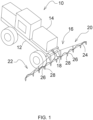
Fig. 1 shows a schematic rear side perspective view of an agricultural sprayer with laterally extended spray booms. -
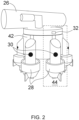
Fig. 2 shows a schematic view of nozzle body with plurality of nozzles mounted on it. -
Fig. 3 shows a detailed view of the nozzle in an active position, a reader assembly, and a transponder tag. - Referring now to
Fig. 1 , there is shown an agricultural machine such as a self-propelledagricultural sprayer 10. In an alternate embodiment, the agricultural machine may be a trailed or a mounted sprayer. - The
agricultural sprayer 10 includes achassis 12 that provides a structure for mounting numerous components associated with theagricultural sprayer 10 thereon. For example, theagricultural sprayer 10 includes aliquid tank 14 which stores a spray liquid comprising chemicals such as liquid/granular fertilizers, pesticides, insecticides, herbicides, fungicides, desiccants and any such chemicals thereof to be sprayed on a field. Theliquid tank 14 is mounted on thechassis 12. Theagricultural sprayer 10 also includes aspray boom assembly 16 located at a rear position of theagricultural sprayer 10. In alternative embodiments, thespray boom assembly 16 may be located at different locations on theagricultural sprayer 10 such as at a front end or in a mid-portion of the agricultural sprayer 10.Thespray boom assembly 16 comprises acenter frame 18 and laterally extendable right and leftbooms spray boom assembly 16 is operable to distribute the chemicals in theliquid tank 14 over a wide area in the field through aconduit 24, associated with thespray boom assembly 16. Thespray boom assembly 14 comprises at least onenozzle body 26, which is placed at a bottom side of thespray boom assembly 16. Thenozzle body 26 comprises of stationary and/or respectively non-rotating portions and arotatable nozzle turret 42 on which a plurality ofnozzles 28 are mounted. The plurality ofnozzles 28 mounted tonozzle turret 42 may be of two or more in numbers. For example, six numbers ofnozzles 28 may be mounted in circular fashion on thenozzle turret 42. Eachnozzle 28 is configured to be placeable into anactive position 44 by rotation of thenozzle turret 42 to discharge liquid chemicals as theagricultural sprayer 10 is propelled along the field of crop or plants. - As shown in
Fig. 2 and3 , atransponder tag 30 is placed on eachnozzle 28 of thenozzle body 26. Preferably, thetransponder tag 30 is a passive radio frequency identification tag. Further, thetag 30 comprises specific information including characteristics of the respective eachnozzle 28, wherein, the specific information of thenozzle 28 includes type of the nozzle, size of the nozzle and spray angle. Further, areader assembly 32 is placed on a location of thespray boom assembly 16 in order to enter a range of communication with therespective transponder tag 30 of therespective nozzle 28 when thenozzle 28 being placed into theactive position 44 by rotation. Preferably, thereader assembly 32, in particular theantenna 34, is placed on the stationary portion of thenozzle body 26 in such way that it enters a range of communication with therespective transponder tag 30 of therespective nozzle 28 when therespective nozzle 28 is placed in theactive position 44 by rotation. Thereader assembly 32 comprises anantenna 34 and acontroller 36. Thereader assembly 32 is configured to emitelectromagnetic waves 38 through theantenna 34 to receive information from theparticular transponder tag 30 of the respective eachnozzle 28. Furthermore, thetransponder tag 30 is configured to receive theelectromagnetic waves 38 and generatessignal 40 back to thereader assembly 32 with the specific information for therespective nozzle 28. Thecontroller 36 is configured to receive the specific information from therespective transponder tag 30 to identify characteristics of therespective nozzle 28 being placed by rotation into theactive position 44. - In an operation, a method is applied which considers placing a
nozzle 28 into anactive position 44 by the rotation of thenozzle turret 42. Preferably, the rotation of thenozzle turret 42 may be achieved automatically with the help of a motor operable from an operator station or remotely. For example, six numbers ofnozzles 28 may be mounted in circular fashion on thenozzle turret 42, out of which two adverse or consecutive oralternate nozzles 28 may be placed in theactive position 44 by the rotation of thenozzle turret 42. The placement of thenozzle 28 in theactive position 44 brings thetransponder tag 30 of thenozzles 28 in theactive position 44 and thereader assembly 34 into the range of communication. Thereader assembly 32 emits primaryelectromagnetic waves 38 through theantenna 34. These primaryelectromagnetic waves 38 are received by therespective transponder tag 30 of thenozzle 28 in theactive position 44. Upon receiving the primaryelectromagnetic waves 38, therespective transponder tag 30 gets energized in order to generate secondaryelectromagnetic waves 40 based on specific information for therespective nozzle 28. Further, therespective transponder tag 30 emits the secondaryelectromagnetic waves 40 which contains specific information for therespective nozzle 28. Then, thereader assembly 32 receives the secondaryelectromagnetic waves 40 based on specific information for therespective nozzle 28. Based on the secondaryelectromagnetic waves 40 along with the specific information for therespective nozzle 28, thecontroller 36 identifies thenozzle 28 in theactive position 44 and its characteristics. Preferably, thecontroller 36 and theantenna 34 together may form thereader assembly 32 as a single or integral device. Alternatively, aseparate controller 36 and aseparate antenna 34 may form thereader assembly 32. Further, thecontroller 36 may vary sprayer settings based on the identifiednozzle 28 in theactive position 44 and its characteristics and the specific spraying requirements. The sprayer settings may include one or more of boom height, spray pressure, sprayer speed, spray drift and combination thereof. - The
controller 36 may store and retrieve data related to specific spraying requirements. Theagricultural machine 10 may comprise a global positioning system (GPS) which may store positioning data of the agricultural machine at a field location. Thecontroller 36 may store and retrieve the positioning data and utilization of theappropriate nozzle 28 as per crop requirement at particular position. This data may be used as historic data in future operations of agricultural machines.
Claims (11)
- An agricultural machine (10) comprising:a chassis (12);a liquid tank (14);a spray boom assembly (16) with a center frame (18) and laterally extendable right and left booms (20, 22);a conduit (24) defining a liquid flow path and associated with the spray boom assembly (16);at least one nozzle body (26) placed at a bottom side of the boom (20, 22), wherein, the nozzle body (26) comprises plurality of nozzles (28);a transponder tag (30) placed on each nozzle (28) of said nozzle body (26), wherein, the tag (30) comprises specific information including characteristics of the respective each nozzle (28);a reader assembly (32) comprising an antenna (34) and a controller (36), wherein, the reader assembly (32) is configured to emit electromagnetic waves (38) through the antenna (34) to receive information from the particular transponder tag (30) of the respective each nozzle (28);wherein, the transponder tag (30) is configured to receive the electromagnetic waves (38) and generates signal (40) back to the reader assembly (32) with the specific information for the respective nozzle (28); characterized in,that the nozzle body (26) comprises a stationary portion and a rotatable nozzle turret (42) and the plurality of nozzles (28) are mounted to the nozzle turret (42), wherein each nozzle (28) is configured to be placeable into an active position (44) by rotation of the nozzle turret (42);that the reader assembly (32) is placed on a location of the spray boom assembly (16) in order to enter a range of communication with the respective transponder tag (30) of the respective nozzle (28) when the nozzle (28) being placed into the active position (44) by rotation; andthat the controller (36) is configured to receive the specific information from the respective transponder tag (30) to identify characteristics of the respective nozzle (28) being placed by rotation into the active position (44).
- The agricultural machine (10) according to claim 1, wherein the transponder tag (30) is a passive radio frequency identification tag.
- The agricultural machine (10) according to claim 1 or 2, wherein the controller (36) is configured to store and retrieve data related to specific spraying requirements.
- The agricultural machine (10) according to one of the claims 1 to 3, wherein the controller (36) is configured to vary sprayer settings based on the identified nozzle (28) in the active position (44) and its characteristics and the specific spraying requirements.
- The agricultural machine (10) according to one of the claims 1 to 4, wherein the sprayer settings include one or more of boom height, spray pressure, sprayer speed and spray drift.
- The agricultural machine (10) according to one of the claims 1 to 5, wherein the specific information of the nozzle (28) includes type of the nozzle, size of the nozzle and spray angle.
- The agricultural machine (10) according to one of the claims 1 to 6, wherein location of the spray boom assembly on which the reader assembly (34) is placed, is the stationary portion of the nozzle body (26) in such way that it enters a range of communication with the respective transponder tag (30) of the respective nozzle (28) when the respective nozzle (28) is placed in the active position (44) by rotation.
- The agricultural machine (10) according to one of the claims 1 to 7, comprising a self-propelled or trailed agricultural sprayer.
- A method of identifying a nozzle (28) in an active position (44) and its characteristics on an agricultural machine of one of the claims 1 to 8, the nozzle (28) is mounted on a spray boom assembly (16) of said agricultural machine,
the method comprising the following steps:placing a nozzle (28) into an active position (44) by rotation;entering a range of communication between the reader assembly (32) and the respective transponder tag (30) of the nozzle (28) in the active position (44);emitting primary electromagnetic waves (38) through an antenna (34) of the reader assembly (32);receiving the primary electromagnetic waves (38) by the respective transponder tag (30); energizing the respective transponder tag (30) upon receiving the primary electromagnetic waves (38) in order to generate secondary electromagnetic waves (40) by the respective transponder tag (30) based on specific information for the respective nozzle (28);emitting the secondary electromagnetic waves (40) by the respective transponder tag (30);receiving the secondary electromagnetic waves (40) by the reader assembly (32); identifying the nozzle (28) in the active position (44) and its characteristics by the controller (36) based on the secondary electromagnetic waves (40). - The method according to claim 9, further comprising the step of storing and retrieving data related to specific spraying requirements by the controller (36).
- The method according to claim 10, further comprising the step of varying sprayer settings by the controller (36) based on the identified nozzle (28) in the active position (44) and its characteristics and the specific spraying requirements.
Priority Applications (2)
| Application Number | Priority Date | Filing Date | Title |
|---|---|---|---|
| EP22188466.1A EP4316239A1 (en) | 2022-08-03 | 2022-08-03 | Agricultural machine and method of identifying a nozzle in an active position and its characteristics on the agricultural machine |
| US18/357,270 US20240040979A1 (en) | 2022-08-03 | 2023-07-24 | Active position nozzle identification system and method |
Applications Claiming Priority (1)
| Application Number | Priority Date | Filing Date | Title |
|---|---|---|---|
| EP22188466.1A EP4316239A1 (en) | 2022-08-03 | 2022-08-03 | Agricultural machine and method of identifying a nozzle in an active position and its characteristics on the agricultural machine |
Publications (1)
| Publication Number | Publication Date |
|---|---|
| EP4316239A1 true EP4316239A1 (en) | 2024-02-07 |
Family
ID=82786263
Family Applications (1)
| Application Number | Title | Priority Date | Filing Date |
|---|---|---|---|
| EP22188466.1A Withdrawn EP4316239A1 (en) | 2022-08-03 | 2022-08-03 | Agricultural machine and method of identifying a nozzle in an active position and its characteristics on the agricultural machine |
Country Status (2)
| Country | Link |
|---|---|
| US (1) | US20240040979A1 (en) |
| EP (1) | EP4316239A1 (en) |
Families Citing this family (1)
| Publication number | Priority date | Publication date | Assignee | Title |
|---|---|---|---|---|
| CN118135684A (en) * | 2024-03-13 | 2024-06-04 | 石河子大学 | A device and method for monitoring agricultural machinery operation information based on RFID |
Citations (5)
| Publication number | Priority date | Publication date | Assignee | Title |
|---|---|---|---|---|
| EP2995382A1 (en) * | 2014-09-15 | 2016-03-16 | Deere & Company | Spray nozzle system, spray boom with such and agricultural vehicle having such spray boom |
| US20170203309A1 (en) * | 2016-01-18 | 2017-07-20 | Pentair Flow Technologies, Llc | Driven Turret Nozzle Assembly System and Method |
| US9824438B2 (en) * | 2015-07-22 | 2017-11-21 | Andreas Reichhardt | Method for testing an agricultural spraying device |
| US20210132588A1 (en) * | 2019-10-31 | 2021-05-06 | Deere & Company | Wireless mobile work machine component detection and control system |
| US20220192174A1 (en) * | 2020-12-21 | 2022-06-23 | Deere & Company | Agricultural sprayer with real-time, on-machine target sensor |
Family Cites Families (3)
| Publication number | Priority date | Publication date | Assignee | Title |
|---|---|---|---|---|
| US10773271B2 (en) * | 2014-06-20 | 2020-09-15 | Deere & Company | Time varying control of the operation of spray systems |
| CN109475114A (en) * | 2016-07-11 | 2019-03-15 | 拜耳农作物科学股份公司 | Spray equipment with containers of unpressurized spray material |
| US12389898B2 (en) * | 2021-02-05 | 2025-08-19 | Deere & Company | Automated nozzle adjustments for plant treatment application |
-
2022
- 2022-08-03 EP EP22188466.1A patent/EP4316239A1/en not_active Withdrawn
-
2023
- 2023-07-24 US US18/357,270 patent/US20240040979A1/en active Pending
Patent Citations (5)
| Publication number | Priority date | Publication date | Assignee | Title |
|---|---|---|---|---|
| EP2995382A1 (en) * | 2014-09-15 | 2016-03-16 | Deere & Company | Spray nozzle system, spray boom with such and agricultural vehicle having such spray boom |
| US9824438B2 (en) * | 2015-07-22 | 2017-11-21 | Andreas Reichhardt | Method for testing an agricultural spraying device |
| US20170203309A1 (en) * | 2016-01-18 | 2017-07-20 | Pentair Flow Technologies, Llc | Driven Turret Nozzle Assembly System and Method |
| US20210132588A1 (en) * | 2019-10-31 | 2021-05-06 | Deere & Company | Wireless mobile work machine component detection and control system |
| US20220192174A1 (en) * | 2020-12-21 | 2022-06-23 | Deere & Company | Agricultural sprayer with real-time, on-machine target sensor |
Also Published As
| Publication number | Publication date |
|---|---|
| US20240040979A1 (en) | 2024-02-08 |
Similar Documents
| Publication | Publication Date | Title |
|---|---|---|
| US9737068B1 (en) | Selective herbicide and responsible pesticide allocation apparatus and system | |
| US8948975B2 (en) | Agriculture combination machines for dispensing compositions | |
| US9836036B2 (en) | Agricultural implement with automated recognition of seed attributes | |
| US8505808B2 (en) | Avoiding the misapplication of contents in one or more containers | |
| US20130110292A1 (en) | Label Based Machine Controls | |
| US20240040979A1 (en) | Active position nozzle identification system and method | |
| Braekman et al. | Effect of spray application technique on spray deposition in greenhouse strawberries and tomatoes | |
| US10279366B2 (en) | Method and device to detect clogged nozzles | |
| US20200170236A1 (en) | Method for applying a spray agent | |
| CN115023295A (en) | Spray system, kit, vehicle and method of use | |
| CN113349038A (en) | Irrigation operation control method and device, storage medium and irrigation equipment | |
| US20230294122A1 (en) | Dynamic drift control | |
| CA3136754A1 (en) | System, method and apparatus for providing variable rate application of applicants to discrete field locations | |
| US5383599A (en) | Agricultural air/liquid sprayer having an inflatable spraying sleeve | |
| EP4595732A1 (en) | Method for controlling work vehicle, work vehicle control program, work vehicle control system, and work vehicle | |
| KR102221603B1 (en) | Distributing system using agricultural drones | |
| JP2025117600A (en) | Work vehicle control method, work vehicle control program, work vehicle control system, and work vehicle | |
| US11938492B2 (en) | Microdroplet nozzle | |
| KR20250075850A (en) | Independent control system for precision pesticide spraying from drones | |
| KR100644431B1 (en) | Agricultural material spreading rate control device | |
| Szymczyk et al. | Innovative Solutions in Crop Protection Technology | |
| US20250244778A1 (en) | Method for controlling work vehicle, work vehicle control program, work vehicle control system, and work vehicle | |
| EP4595747A1 (en) | Method for controlling work vehicle, work vehicle control program, work vehicle control system, and work vehicle | |
| KR200343358Y1 (en) | Uninhabited aircraft crop-duster | |
| EP4248748A1 (en) | Spraying machine control method, spraying machine control program, and spraying machine |
Legal Events
| Date | Code | Title | Description |
|---|---|---|---|
| PUAI | Public reference made under article 153(3) epc to a published international application that has entered the european phase |
Free format text: ORIGINAL CODE: 0009012 |
|
| STAA | Information on the status of an ep patent application or granted ep patent |
Free format text: STATUS: THE APPLICATION HAS BEEN PUBLISHED |
|
| AK | Designated contracting states |
Kind code of ref document: A1 Designated state(s): AL AT BE BG CH CY CZ DE DK EE ES FI FR GB GR HR HU IE IS IT LI LT LU LV MC MK MT NL NO PL PT RO RS SE SI SK SM TR |
|
| STAA | Information on the status of an ep patent application or granted ep patent |
Free format text: STATUS: THE APPLICATION IS DEEMED TO BE WITHDRAWN |
|
| 18D | Application deemed to be withdrawn |
Effective date: 20240808 |