EP4315974B1 - Wiederholungen eines gemeinsam genutzten physikalischen uplink-kanals während der übergabe - Google Patents
Wiederholungen eines gemeinsam genutzten physikalischen uplink-kanals während der übergabe Download PDFInfo
- Publication number
- EP4315974B1 EP4315974B1 EP22711133.3A EP22711133A EP4315974B1 EP 4315974 B1 EP4315974 B1 EP 4315974B1 EP 22711133 A EP22711133 A EP 22711133A EP 4315974 B1 EP4315974 B1 EP 4315974B1
- Authority
- EP
- European Patent Office
- Prior art keywords
- mcg
- source
- pusch
- slots
- target
- Prior art date
- Legal status (The legal status is an assumption and is not a legal conclusion. Google has not performed a legal analysis and makes no representation as to the accuracy of the status listed.)
- Active
Links
Images


Classifications
-
- H—ELECTRICITY
- H04—ELECTRIC COMMUNICATION TECHNIQUE
- H04W—WIRELESS COMMUNICATION NETWORKS
- H04W36/00—Hand-off or reselection arrangements
- H04W36/0005—Control or signalling for completing the hand-off
- H04W36/0055—Transmission or use of information for re-establishing the radio link
- H04W36/0069—Transmission or use of information for re-establishing the radio link in case of dual connectivity, e.g. decoupled uplink/downlink
- H04W36/00692—Transmission or use of information for re-establishing the radio link in case of dual connectivity, e.g. decoupled uplink/downlink using simultaneous multiple data streams, e.g. cooperative multipoint [CoMP], carrier aggregation [CA] or multiple input multiple output [MIMO]
-
- H—ELECTRICITY
- H04—ELECTRIC COMMUNICATION TECHNIQUE
- H04W—WIRELESS COMMUNICATION NETWORKS
- H04W36/00—Hand-off or reselection arrangements
- H04W36/0005—Control or signalling for completing the hand-off
- H04W36/0055—Transmission or use of information for re-establishing the radio link
- H04W36/0072—Transmission or use of information for re-establishing the radio link of resource information of target access point
-
- H—ELECTRICITY
- H04—ELECTRIC COMMUNICATION TECHNIQUE
- H04L—TRANSMISSION OF DIGITAL INFORMATION, e.g. TELEGRAPHIC COMMUNICATION
- H04L1/00—Arrangements for detecting or preventing errors in the information received
- H04L1/08—Arrangements for detecting or preventing errors in the information received by repeating transmission, e.g. Verdan system
-
- H—ELECTRICITY
- H04—ELECTRIC COMMUNICATION TECHNIQUE
- H04W—WIRELESS COMMUNICATION NETWORKS
- H04W36/00—Hand-off or reselection arrangements
- H04W36/16—Performing reselection for specific purposes
- H04W36/18—Performing reselection for specific purposes for allowing seamless reselection, e.g. soft reselection
- H04W36/185—Performing reselection for specific purposes for allowing seamless reselection, e.g. soft reselection using make before break
-
- H—ELECTRICITY
- H04—ELECTRIC COMMUNICATION TECHNIQUE
- H04W—WIRELESS COMMUNICATION NETWORKS
- H04W36/00—Hand-off or reselection arrangements
- H04W36/34—Reselection control
- H04W36/36—Reselection control by user or terminal equipment
- H04W36/362—Conditional handover
-
- H—ELECTRICITY
- H04—ELECTRIC COMMUNICATION TECHNIQUE
- H04W—WIRELESS COMMUNICATION NETWORKS
- H04W72/00—Local resource management
- H04W72/04—Wireless resource allocation
- H04W72/044—Wireless resource allocation based on the type of the allocated resource
- H04W72/0446—Resources in time domain, e.g. slots or frames
-
- H—ELECTRICITY
- H04—ELECTRIC COMMUNICATION TECHNIQUE
- H04W—WIRELESS COMMUNICATION NETWORKS
- H04W72/00—Local resource management
- H04W72/12—Wireless traffic scheduling
- H04W72/1263—Mapping of traffic onto schedule, e.g. scheduled allocation or multiplexing of flows
- H04W72/1268—Mapping of traffic onto schedule, e.g. scheduled allocation or multiplexing of flows of uplink data flows
-
- H—ELECTRICITY
- H04—ELECTRIC COMMUNICATION TECHNIQUE
- H04W—WIRELESS COMMUNICATION NETWORKS
- H04W36/00—Hand-off or reselection arrangements
- H04W36/08—Reselecting an access point
- H04W36/083—Reselecting an access point wherein at least one of the access points is a moving node
Definitions
- aspects of the present disclosure generally relate to wireless communication and to techniques and apparatuses for physical uplink shared channel (PUSCH) repetitions during handover.
- PUSCH physical uplink shared channel
- Wireless communication systems are widely deployed to provide various telecommunication services such as telephony, video, data, messaging, and broadcasts.
- Typical wireless communication systems may employ multiple-access technologies capable of supporting communication with multiple users by sharing available system resources (e.g., bandwidth, transmit power, or the like).
- multiple-access technologies include code division multiple access (CDMA) systems, time division multiple access (TDMA) systems, frequency-division multiple access (FDMA) systems, orthogonal frequency-division multiple access (OFDMA) systems, single-carrier frequency-division multiple access (SC-FDMA) systems, time division synchronous code division multiple access (TD-SCDMA) systems, and Long Term Evolution (LTE).
- LTE/LTE-Advanced is a set of enhancements to the Universal Mobile Telecommunications System (UMTS) mobile standard promulgated by the Third Generation Partnership Project (3GPP).
- UMTS Universal Mobile Telecommunications System
- a wireless network may include a number of base stations (BSs) that can support communication for a number of user equipment (UEs).
- UE may communicate with a BS via the downlink and uplink.
- Downlink (or “forward link”) refers to the communication link from the BS to the UE
- uplink (or “reverse link”) refers to the communication link from the UE to the BS.
- a BS may be referred to as a Node B, a gNB, an access point (AP), a radio head, a transmit receive point (TRP), a New Radio (NR) BS, a 5G Node B, or the like.
- NR which may also be referred to as 5G
- 5G is a set of enhancements to the LTE mobile standard promulgated by the 3GPP.
- NR is designed to better support mobile broadband Internet access by improving spectral efficiency, lowering costs, improving services, making use of new spectrum, and better integrating with other open standards using orthogonal frequency division multiplexing (OFDM) with a cyclic prefix (CP) (CP-OFDM) on the downlink (DL), using CP-OFDM and/or SC-FDM (e.g., also known as discrete Fourier transform spread OFDM (DFT-s-OFDM)) on the uplink (UL), as well as supporting beamforming, multiple-input multiple-output (MIMO) antenna technology, and carrier aggregation.
- OFDM orthogonal frequency division multiplexing
- SC-FDM e.g., also known as discrete Fourier transform spread OFDM (DFT-s-OFDM)
- MIMO multiple-input multiple-output
- a user equipment may receive, from a source base station (BS), a handover message or the beam or panel selection message including multibeam or multi-panel information identifying a first one or more beams or panels to remain with the source BS and a second one or more beams or panels to switch from the source BS to a target BS during a handover procedure.
- the UE may perform the handover procedure to switch from the source BS to the target BS with the first one or more beams or panels for communication with the source BS and the second one or more beams or panels for communication with the target BS.
- a method of wireless communication performed by a UE includes transmitting, to a source base station associated with a source master cell group (MCG), a physical uplink shared channel (PUSCH) repetition in each of one or more slots of the source MCG during a dual active protocol stack (DAPS)-based handover of the UE from the source MCG to a target MCG; and performing, to a target base station associated with the target MCG, an uplink transmission in one or more slots to the target MCG during the DAPS-based handover, wherein PUSCH repetitions associated with the source MCG that overlap in time with the uplink transmission to the target MCG are canceled and a counting of the PUSCH repetitions is based at least in part on slots of the source MCG associated with canceled PUSCH repetitions.
- MCG source master cell group
- PUSCH physical uplink shared channel
- a method of wireless communication performed by a source base station includes transmitting, to a UE, a configuration associated with a quantity of PUSCH repetitions; and receiving, from the UE, a PUSCH repetition in each of one or more slots of a source MCG associated with the source base station during a DAPS-based handover of the UE from the source MCG to a target MCG, wherein PUSCH repetitions that overlap in time with an uplink transmission to the target MCG are canceled and a counting of the PUSCH repetitions is based at least in part on slots of the source MCG associated with canceled PUSCH repetitions.
- a UE for wireless communication includes a memory and one or more processors, operatively coupled to the memory, configured to: transmit, to a source base station associated with a source MCG, a PUSCH repetition in each of one or more slots of the source MCG during a DAPS-based handover of the UE from the source MCG to a target MCG; and perform, to a target base station associated with the target MCG, an uplink transmission in one or more slots to the target MCG during the DAPS-based handover, wherein PUSCH repetitions associated with the source MCG that overlap in time with the uplink transmission to the target MCG are canceled and a counting of the PUSCH repetitions is based at least in part on slots of the source MCG associated with canceled PUSCH repetitions.
- a source base station for wireless communication includes a memory and one or more processors, operatively coupled to the memory, configured to: transmit, to a UE, a configuration associated with a quantity of PUSCH repetitions; and receive, from the UE, a PUSCH repetition in each of one or more slots of a source MCG associated with the source base station during a DAPS-based handover of the UE from the source MCG to a target MCG, wherein PUSCH repetitions that overlap in time with an uplink transmission to the target MCG are canceled and a counting of the PUSCH repetitions is based at least in part on slots of the source MCG associated with canceled PUSCH repetitions.
- a non-transitory computer-readable medium storing a set of instructions for wireless communication includes one or more instructions that, when executed by one or more processors of a UE, cause the UE to: transmit, to a source base station associated with a source MCG, a PUSCH repetition in each of one or more slots of the source MCG during a DAPS-based handover of the UE from the source MCG to a target MCG; and perform, to a target base station associated with the target MCG, an uplink transmission in one or more slots to the target MCG during the DAPS-based handover, wherein PUSCH repetitions associated with the source MCG that overlap in time with the uplink transmission to MCG are canceled and a counting of the PUSCH repetitions is based at least in part on slots of the source MCG associated with canceled PUSCH repetitions.
- a non-transitory computer-readable medium storing a set of instructions for wireless communication includes one or more instructions that, when executed by one or more processors of a source base station, cause the source base station to: transmit, to a UE, a configuration associated with a quantity of PUSCH repetitions; and receive, from the UE, a PUSCH repetition in each of one or more slots of a source MCG associated with the source base station during a DAPS-based handover of the UE from the source MCG to a target MCG, wherein PUSCH repetitions that overlap in time with an uplink transmission to the target MCG are canceled and a counting of the PUSCH repetitions is based at least in part on slots of the source MCG associated with canceled PUSCH repetitions.
- an apparatus for wireless communication includes means for transmitting, to a source base station associated with a source MCG, a PUSCH repetition in each of one or more slots of the source MCG during a DAPS-based handover of the apparatus from the source MCG to a target MCG; and means for performing, to a target base station associated with the target MCG, an uplink transmission in one or more slots to the target MCG during the DAPS-based handover, wherein PUSCH repetitions associated with the source MCG that overlap in time with the uplink transmission to MCG are canceled and a counting of the PUSCH repetitions is based at least in part on slots of the source MCG associated with canceled PUSCH repetitions.
- a source apparatus for wireless communication includes means for transmitting, to a UE, a configuration associated with a quantity of PUSCH repetitions; and means for receiving, from the UE, a PUSCH repetition in each of one or more slots of a source MCG associated with the source apparatus during a DAPS-based handover of the UE from the source MCG to a target MCG, wherein PUSCH repetitions that overlap in time with an uplink transmission to the target MCG are canceled and a counting of the PUSCH repetitions is based at least in part on slots of the source MCG associated with canceled PUSCH repetitions.
- aspects generally include a method, apparatus, system, computer program product, non-transitory computer-readable medium, user equipment, base station, wireless communication device, and/or processing system as substantially described herein with reference to and as illustrated by the drawings and specification.
- aspects are described in the present disclosure by illustration to some examples, those skilled in the art will understand that such aspects may be implemented in many different arrangements and scenarios.
- Techniques described herein may be implemented using different platform types, devices, systems, shapes, sizes, and/or packaging arrangements.
- some aspects may be implemented via integrated chip embodiments or other non-module-component based devices (e.g., end-user devices, vehicles, communication devices, computing devices, industrial equipment, retail/purchasing devices, medical devices, or artificial intelligence-enabled devices).
- aspects may be implemented in chip-level components, modular components, non-modular components, non-chip-level components, device-level components, or system-level components.
- Devices incorporating described aspects and features may include additional components and features for implementation and practice of claimed and described aspects.
- transmission and reception of wireless signals may include a number of components for analog and digital purposes (e.g., hardware components including antennas, RF chains, power amplifiers, modulators, buffers, processor(s), interleavers, adders, or summers). It is intended that aspects described herein may be practiced in a wide variety of devices, components, systems, distributed arrangements, or end-user devices of varying size, shape, and constitution.
- aspects may be described herein using terminology commonly associated with a 5G or NR radio access technology (RAT), aspects of the present disclosure can be applied to other RATs, such as a 3G RAT, a 4G RAT, and/or a RAT subsequent to 5G (e.g., 6G).
- RAT radio access technology
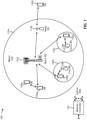
- Fig. 1 is a diagram illustrating an example of a wireless network 100, in accordance with the present disclosure.
- the wireless network 100 may be or may include elements of a 5G (NR) network and/or an LTE network, among other examples.
- the wireless network 100 may include a number of base stations 110 (shown as BS 110a, BS 110b, BS 110c, and BS 110d) and other network entities.
- a base station (BS) is an entity that communicates with user equipment (UEs) and may also be referred to as an NR BS, a Node B, a gNB, a 5G node B (NB), an access point, a transmit receive point (TRP), or the like.
- Each BS may provide communication coverage for a particular geographic area.
- the term "cell" can refer to a coverage area of a BS and/or a BS subsystem serving this coverage area, depending on the context in which the term is used.
- a BS may provide communication coverage for a macro cell, a pico cell, a femto cell, and/or another type of cell.
- a macro cell may cover a relatively large geographic area (e.g., several kilometers in radius) and may allow unrestricted access by UEs with service subscription.
- a pico cell may cover a relatively small geographic area and may allow unrestricted access by UEs with service subscription.
- a femto cell may cover a relatively small geographic area (e.g., a home) and may allow restricted access by UEs having association with the femto cell (e.g., UEs in a closed subscriber group (CSG)).
- a BS for a macro cell may be referred to as a macro BS.
- a BS for a pico cell may be referred to as a pico BS.
- a BS for a femto cell may be referred to as a femto BS or a home BS.
- a BS 110a may be a macro BS for a macro cell 102a
- a BS 110b may be a pico BS for a pico cell 102b
- a BS 110c may be a femto BS for a femto cell 102c.
- a BS may support one or multiple (e.g., three) cells.
- the terms "eNB”, “base station”, “NR BS”, “gNB”, “TRP”, “AP”, “node B", “5G NB”, and “cell” may be used interchangeably herein.
- a cell may not necessarily be stationary, and the geographic area of the cell may move according to the location of a mobile BS.
- the BSs may be interconnected to one another and/or to one or more other BSs or network nodes (not shown) in the wireless network 100 through various types of backhaul interfaces, such as a direct physical connection or a virtual network, using any suitable transport network.
- Wireless network 100 may also include relay stations.
- a relay station is an entity that can receive a transmission of data from an upstream station (e.g., a BS or a UE) and send a transmission of the data to a downstream station (e.g., a UE or a BS).
- a relay station may also be a UE that can relay transmissions for other UEs.
- a relay BS 110d may communicate with macro BS 110a and a UE 120d in order to facilitate communication between BS 110a and UE 120d.
- a relay BS may also be referred to as a relay station, a relay base station, a relay, or the like.
- Wireless network 100 may be a heterogeneous network that includes BSs of different types, such as macro BSs, pico BSs, femto BSs, relay BSs, or the like. These different types of BSs may have different transmit power levels, different coverage areas, and different impacts on interference in wireless network 100. For example, macro BSs may have a high transmit power level (e.g., 5 to 40 watts) whereas pico BSs, femto BSs, and relay BSs may have lower transmit power levels (e.g., 0.1 to 2 watts).
- macro BSs may have a high transmit power level (e.g., 5 to 40 watts)
- pico BSs, femto BSs, and relay BSs may have lower transmit power levels (e.g., 0.1 to 2 watts).
- a network controller 130 may couple to a set of BSs and may provide coordination and control for these BSs.
- Network controller 130 may communicate with the BSs via a backhaul.
- the BSs may also communicate with one another, e.g., directly or indirectly via a wireless or wireline backhaul.
- UEs 120 may be dispersed throughout wireless network 100, and each UE may be stationary or mobile.
- a UE may also be referred to as an access terminal, a terminal, a mobile station, a subscriber unit, a station, or the like.
- a UE may be a cellular phone (e.g., a smart phone), a personal digital assistant (PDA), a wireless modem, a wireless communication device, a handheld device, a laptop computer, a cordless phone, a wireless local loop (WLL) station, a tablet, a camera, a gaming device, a netbook, a smartbook, an ultrabook, a medical device or equipment, biometric sensors/devices, wearable devices (smart watches, smart clothing, smart glasses, smart wrist bands, smart jewelry (e.g., smart ring, smart bracelet)), an entertainment device (e.g., a music or video device, or a satellite radio), a vehicular component or sensor, smart meters/sensors, industrial manufacturing equipment, a global positioning system device, or any other suitable device that is configured to communicate via a wireless or wired medium.
- a cellular phone e.g., a smart phone
- PDA personal digital assistant
- WLL wireless local loop
- Some UEs may be considered machine-type communication (MTC) or evolved or enhanced machine-type communication (eMTC) UEs.
- MTC and eMTC UEs include, for example, robots, drones, remote devices, sensors, meters, monitors, and/or location tags, that may communicate with a base station, another device (e.g., remote device), or some other entity.
- a wireless node may provide, for example, connectivity for or to a network (e.g., a wide area network such as Internet or a cellular network) via a wired or wireless communication link.
- Some UEs may be considered Internet-of-Things (IoT) devices, and/or may be implemented as NB-IoT (narrowband internet of things) devices.
- IoT Internet-of-Things
- NB-IoT narrowband internet of things
- UE 120 may be included inside a housing that houses components of UE 120, such as processor components and/or memory components.
- the processor components and the memory components may be coupled together.
- the processor components e.g., one or more processors
- the memory components e.g., a memory
- the processor components and the memory components may be operatively coupled, communicatively coupled, electronically coupled, and/or electrically coupled.
- any number of wireless networks may be deployed in a given geographic area.
- Each wireless network may support a particular RAT and may operate on one or more frequencies.
- a RAT may also be referred to as a radio technology, an air interface, or the like.
- a frequency may also be referred to as a carrier, a frequency channel, or the like.
- Each frequency may support a single RAT in a given geographic area in order to avoid interference between wireless networks of different RATs.
- NR or 5G RAT networks may be deployed.
- two or more UEs 120 may communicate directly using one or more sidelink channels (e.g., without using a base station 110 as an intermediary to communicate with one another).
- the UEs 120 may communicate using peer-to-peer (P2P) communications, device-to-device (D2D) communications, a vehicle-to-everything (V2X) protocol (e.g., which may include a vehicle-to-vehicle (V2V) protocol or a vehicle-to-infrastructure (V2I) protocol), and/or a mesh network.
- V2X vehicle-to-everything
- the UE 120 may perform scheduling operations, resource selection operations, and/or other operations described elsewhere herein as being performed by the base station 110.
- Devices of wireless network 100 may communicate using the electromagnetic spectrum, which may be subdivided based on frequency or wavelength into various classes, bands, channels, or the like.
- devices of wireless network 100 may communicate using an operating band having a first frequency range (FR1), which may span from 410 MHz to 7.125 GHz, and/or may communicate using an operating band having a second frequency range (FR2), which may span from 24.25 GHz to 52.6 GHz.
- FR1 and FR2 are sometimes referred to as mid-band frequencies.
- FR1 is often referred to as a "sub-6 GHz" band.
- FR2 is often referred to as a "millimeter wave” band despite being different from the extremely high frequency (EHF) band (30 GHz - 300 GHz) which is identified by the International Telecommunications Union (ITU) as a “millimeter wave” band.
- EHF extremely high frequency
- ITU International Telecommunications Union
- sub-6 GHz or the like, if used herein, may broadly represent frequencies less than 6 GHz, frequencies within FR1, and/or mid-band frequencies (e.g., greater than 7.125 GHz).
- millimeter wave may broadly represent frequencies within the EHF band, frequencies within FR2, and/or mid-band frequencies (e.g., less than 24.25 GHz). It is contemplated that the frequencies included in FR1 and FR2 may be modified, and techniques described herein are applicable to those modified frequency ranges.
- Fig. 1 is provided as an example. Other examples may differ from what is described with regard to Fig. 1 .
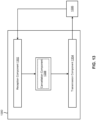
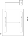
- Fig. 2 is a diagram illustrating an example 200 of a base station 110 in communication with a UE 120 in a wireless network 100, in accordance with the present disclosure.
- Base station 110 may be equipped with T antennas 234a through 234t
- UE 120 may be equipped with R antennas 252a through 252r, where in general T ⁇ 1 and R ⁇ 1.
- a transmit processor 220 may receive data from a data source 212 for one or more UEs, select one or more modulation and coding schemes (MCS) for each UE based at least in part on channel quality indicators (CQIs) received from the UE, process (e.g., encode and modulate) the data for each UE based at least in part on the MCS(s) selected for the UE, and provide data symbols for all UEs. Transmit processor 220 may also process system information (e.g., for semi-static resource partitioning information (SRPI)) and control information (e.g., CQI requests, grants, and/or upper layer signaling) and provide overhead symbols and control symbols.
- MCS modulation and coding schemes
- Transmit processor 220 may also generate reference symbols for reference signals (e.g., a cell-specific reference signal (CRS) or a demodulation reference signal (DMRS)) and synchronization signals (e.g., a primary synchronization signal (PSS) or a secondary synchronization signal (SSS)).
- a transmit (TX) multiple-input multiple-output (MIMO) processor 230 may perform spatial processing (e.g., precoding) on the data symbols, the control symbols, the overhead symbols, and/or the reference symbols, if applicable, and may provide T output symbol streams to T modulators (MODs) 232a through 232t. Each modulator 232 may process a respective output symbol stream (e.g., for OFDM) to obtain an output sample stream.
- TX transmit
- MIMO multiple-input multiple-output
- Each modulator 232 may process a respective output symbol stream (e.g., for OFDM) to obtain an output sample stream.
- Each modulator 232 may further process (e.g., convert to analog, amplify, filter, and upconvert) the output sample stream to obtain a downlink signal.
- T downlink signals from modulators 232a through 232t may be transmitted via T antennas 234a through 234t, respectively.
- antennas 252a through 252r may receive the downlink signals from base station 110 and/or other base stations and may provide received signals to demodulators (DEMODs) 254a through 254r, respectively.
- Each demodulator 254 may condition (e.g., filter, amplify, downconvert, and digitize) a received signal to obtain input samples.
- Each demodulator 254 may further process the input samples (e.g., for OFDM) to obtain received symbols.
- a MIMO detector 256 may obtain received symbols from all R demodulators 254a through 254r, perform MIMO detection on the received symbols if applicable, and provide detected symbols.
- a receive processor 258 may process (e.g., demodulate and decode) the detected symbols, provide decoded data for UE 120 to a data sink 260, and provide decoded control information and system information to a controller/processor 280.
- controller/processor may refer to one or more controllers, one or more processors, or a combination thereof.
- a channel processor may determine a reference signal received power (RSRP) parameter, a received signal strength indicator (RSSI) parameter, a reference signal received quality (RSRQ) parameter, and/or a channel quality indicator (CQI) parameter, among other examples.
- RSRP reference signal received power
- RSSI received signal strength indicator
- RSSQ reference signal received quality
- CQI channel quality indicator
- one or more components of UE 120 may be included in a housing 284.
- Network controller 130 may include communication unit 294, controller/processor 290, and memory 292.
- Network controller 130 may include, for example, one or more devices in a core network.
- Network controller 130 may communicate with base station 110 via communication unit 294.
- Antennas may include, or may be included within, one or more antenna panels, antenna groups, sets of antenna elements, and/or antenna arrays, among other examples.
- An antenna panel, an antenna group, a set of antenna elements, and/or an antenna array may include one or more antenna elements.
- An antenna panel, an antenna group, a set of antenna elements, and/or an antenna array may include a set of coplanar antenna elements and/or a set of non-coplanar antenna elements.
- An antenna panel, an antenna group, a set of antenna elements, and/or an antenna array may include antenna elements within a single housing and/or antenna elements within multiple housings.
- An antenna panel, an antenna group, a set of antenna elements, and/or an antenna array may include one or more antenna elements coupled to one or more transmission and/or reception components, such as one or more components of Fig. 2 .
- a transmit processor 264 may receive and process data from a data source 262 and control information (e.g., for reports that include RSRP, RSSI, RSRQ, and/or CQI) from controller/processor 280. Transmit processor 264 may also generate reference symbols for one or more reference signals. The symbols from transmit processor 264 may be precoded by a TX MIMO processor 266 if applicable, further processed by modulators 254a through 254r (e.g., for DFT-s-OFDM or CP-OFDM), and transmitted to base station 110.
- control information e.g., for reports that include RSRP, RSSI, RSRQ, and/or CQI
- Transmit processor 264 may also generate reference symbols for one or more reference signals.
- the symbols from transmit processor 264 may be precoded by a TX MIMO processor 266 if applicable, further processed by modulators 254a through 254r (e.g., for DFT-s-OFDM or CP-OFDM
- a modulator and a demodulator (e.g., MOD/DEMOD 254) of the UE 120 may be included in a modem of the UE 120.
- the UE 120 includes a transceiver.
- the transceiver may include any combination of antenna(s) 252, modulators and/or demodulators 254, MIMO detector 256, receive processor 258, transmit processor 264, and/or TX MIMO processor 266.
- the transceiver may be used by a processor (e.g., controller/processor 280) and memory 282 to perform aspects of any of the methods described herein (for example, as described with reference to Figs. 6-12 ).
- the uplink signals from UE 120 and other UEs may be received by antennas 234, processed by demodulators 232, detected by a MIMO detector 236 if applicable, and further processed by a receive processor 238 to obtain decoded data and control information sent by UE 120.
- Receive processor 238 may provide the decoded data to a data sink 239 and the decoded control information to controller/processor 240.
- Base station 110 may include communication unit 244 and communicate to network controller 130 via communication unit 244.
- Base station 110 may include a scheduler 246 to schedule UEs 120 for downlink and/or uplink communications.
- a modulator and a demodulator (e.g., MOD/DEMOD 232) of the base station 110 may be included in a modem of the base station 110.
- the base station 110 includes a transceiver.
- the transceiver may include any combination of antenna(s) 234, modulators and/or demodulators 232, MIMO detector 236, receive processor 238, transmit processor 220, and/or TX MIMO processor 230.
- the transceiver may be used by a processor (e.g., controller/processor 240) and memory 242 to perform aspects of any of the methods described herein (for example, as described with reference to Figs. 6-12 ).
- Controller/processor 240 of base station 110, controller/processor 280 of UE 120, and/or any other component(s) of Fig. 2 may perform one or more techniques associated with PUSCH repetitions during handover, as described in more detail elsewhere herein.
- controller/processor 240 of base station 110, controller/processor 280 of UE 120, and/or any other component(s) of Fig. 2 may perform or direct operations of, for example, process 1100 of Fig. 11 , process 1200 of Fig. 12 , and/or other processes as described herein.
- Memories 242 and 282 may store data and program codes for base station 110 and UE 120, respectively.
- memory 242 and/or memory 282 may include a non-transitory computer-readable medium storing one or more instructions (e.g., code and/or program code) for wireless communication.
- the one or more instructions when executed (e.g., directly, or after compiling, converting, and/or interpreting) by one or more processors of the base station 110 and/or the UE 120, may cause the one or more processors, the UE 120, and/or the base station 110 to perform or direct operations of, for example, process 1100 of Fig. 11 , process 1200 of Fig. 12 , and/or other processes as described herein.
- executing instructions may include running the instructions, converting the instructions, compiling the instructions, and/or interpreting the instructions, among other examples.
- the means for the UE to perform operations described herein may include, for example, one or more of antenna 252, demodulator 254, MIMO detector 256, receive processor 258, transmit processor 264, TX MIMO processor 266, modulator 254, controller/processor 280, or memory 282.
- the UE includes means for canceling the PUSCH repetitions associated with the source MCG that overlap in time with the uplink transmission to MCG.
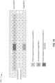
- the PUSCH for VoIP may be associated with FDD or TDD with a certain slot configuration (e.g., DDDSU, or DDDSUDDSUU).
- a potential bottleneck channel may be a PUSCH for eMBB, which may be associated with a certain slot configuration (e.g., DDDSU or DDSU).
- another potential bottleneck channel may be a PUSCH for VoIP with a certain slot configuration (e.g., DDDSU or DDSU).
Landscapes
- Engineering & Computer Science (AREA)
- Computer Networks & Wireless Communication (AREA)
- Signal Processing (AREA)
- Mobile Radio Communication Systems (AREA)
Claims (15)
- Ein Verfahren (1100) für eine drahtlose Kommunikation, das durch ein Benutzergerät (User Equipment bzw. UE) (120) durchgeführt wird, aufweisend:Senden (1110), an eine Quell-Basisstation (110), die mit einer Quell-Masterzellengruppe (Master Cell Group bzw. MCG) assoziiert ist, einer Gemeinsamer-physikalischer-Aufwärtsstreckekanal (PUSCH)-Wiederholung in jedem eines oder mehrerer Schlitze der Quell-MCG während eines DAPS (Dual Active Protocol Stack)-basierten Handovers des UE von der Quell-MCG zu einer Ziel-MCG, undDurchführen (1120), an eine Ziel-Basisstation (110), die mit der Ziel-MCG assoziiert ist, einer Aufwärtsstrecke-Sendung in einem oder mehreren Schlitzen an die Ziel-MCG während des DAPS-basierten Handovers, wobei mit der Quell-MCG assoziierte PUSCH-Wiederholungen, die in der Zeit mit der Aufwärtsstrecke-Sendung an die Ziel-MCG überlappen, aufgehoben werden und eine Zählung der PUSCH-Wiederholungen wenigstens teilweise auf Schlitzen der mit den aufgehobenen PUSCH-Wiederholungen assoziierten Quell-MCG basiert.
- Verfahren nach Anspruch 1, wobei das Zählen der PUSCH-Wiederholungen ein Zählen der Schlitze der mit den aufgehobenen PUSCH-Wiederholungen assoziierten Quell-MCG aufweist.
- Verfahren nach Anspruch 1, wobei das Zählen der PUSCH-Wiederholungen kein Zählen der Schlitze der mit den aufgehobenen PUSCH-Wiederholungen assoziierten Quell-MCG aufweist.
- Verfahren nach Anspruch 1, wobei die mit der Quell-MCD assoziierten PUSCH-Wiederholungen vollständig in der Zeit mit der Aufwärtsstrecke-Sendung an die Ziel-MCG überlappen.
- Verfahren nach Anspruch 1, wobei die mit der Quell-MCG assoziierten PUSCH-Wiederholungen teilweise in der Zeit mit der Aufwärtsstrecke-Sendung an die Ziel-MCG überlappen.
- Verfahren nach Anspruch 1, wobei die Aufwärtsstrecke-Sendung in dem einen oder den mehreren Schlitzen der Ziel-MCG während des DAPS-basierten Handovers eine der Folgenden ist: eine Physikalischer-Aufwärtsstrecke-Steuerkanal-Sendung, eine PUSCH-Sendung, ein Sondierungsreferenzsignal, eine Physikalischer-Direktzugriffskanal-Sendung oder einer Msg3 (Message 3)-PUSCH-Sendung.
- Verfahren nach Anspruch 1, wobei das DAPS-basierte Handover mit einem Frequenzduplex (FDD)-zu-FDD-Handover, einem Zeitduplex (TDD)-zu-TDD-Handover, einem TDD-zu-FDD-Handover oder einem FDD-zu-TDD-Handover assoziiert ist, wobei der FDD mit einem gepaarten Spektrum assoziiert ist und der TDD mit einem nicht-gepaarten Spektrum assoziiert ist.
- Verfahren nach Anspruch 1, wobei die PUSCH-Wiederholungen mit einer PUSCH-Wiederholung des Typs A assoziiert sind, in der eine gleiche Symbolzuweisung in jedem des einen oder der mehreren Schlitze der Quell-MCG angewendet wird.
- Verfahren nach Anspruch 1, das weiterhin aufweist:
Aufheben der mit der Quell-MCG assoziierten PUSCH-Wiederholungen, die in der Zeit mit der Aufwärtsstrecke-Sendung an die Ziel-MCG überlappen. - Verfahren nach Anspruch 1, das weiterhin aufweist:Aufheben der mit der Quell-MCG assoziierten PUSCH-Wiederholungen basierend wenigstens teilweise auf einer fehlenden UE-Fähigkeit für eine gemeinsame Nutzung einer Leistung zwischen der Quell-MCG und der Ziel-MCG während des DAPS-basierten Handovers, oderAufheben der mit der Quell-MCG assoziierten PUSCH-Wiederholungen basierend wenigstens teilweise auf einer UE-Fähigkeit für das Aufheben von Aufwärtsstrecke-Sendungen während des DAPS-basierten Handovers.
- Verfahren nach Anspruch 1, das weiterhin aufweist:
Aufheben der mit der Quell-MCG assoziierten PUSCH-Wiederholungen basierend wenigstens teilweise auf einem Intra-Frequenz-DAPS-basierten Handover. - Verfahren nach Anspruch 1, wobei:der eine oder die mehreren Schlitze der Quell-MCG einen oder mehrere Aufwärtsstrecke-Schlitze oder spezielle Schlitze aufweisen, undder eine oder die mehreren Schlitze der Ziel-MCG einen oder mehrere Aufwärtsstrecke-Schlitze oder spezielle Schlitze aufweisen.
- Ein Verfahren (1200) für eine drahtlose Kommunikation, das durch eine Quell-Basisstation (110) durchgeführt wird, aufweisend:Senden (1210), an ein Benutzergerät (User Equipment) bzw. UE) (120), einer mit einer Anzahl von Gemeinsamer-physikalischer-Aufwärtsstreckekanal (PUSCH)-Wiederholungen assoziierten Konfiguration, undEmpfangen (1220), von dem UE, einer PUSCH-Wiederholung in jedem eines oder mehrerer Schlitze einer Quell-Masterzellengruppe (Master Cell Group bzw. MCG), die mit der Quell-Basisstation assoziiert ist, während eines DAPS (Dual Active Protocol Stack)-basierten Handovers des UE von der Quell-MCG zu einer Ziel-MCG, wobei PUSCH-Wiederholungen, die in der Zeit mit einer Aufwärtsstrecke-Sendung an die Ziel-MCG überlappen, aufgehoben werden und eine Zählung der PUSCH-Wiederholungen wenigstens teilweise auf Schlitzen der mit aufgehobenen PUSCH-Wiederholungen assoziierten Quell-MCG basiert.
- Ein Benutzergerät (User Equipment bzw. UE) (120) für eine drahtlose Kommunikation, aufweisend:einen Speicher (282), undeinen oder mehrere Prozessoren (258, 264, 280), die konfiguriert sind für eine Kopplung mit dem Speicher und weiterhin konfiguriert sind zum:Senden, an eine Quell-Basisstation (110), die mit einer Quell-Masterzellengruppe (Master Cell Group bzw. MCG) assoziiert ist, einer Gemeinsamer-physikalischer-Aufwärtsstreckekanal (PUSCH)-Wiederholung in jedem eines oder mehrerer Schlitze der Quell-MCG während eines DAPS (Dual Active Protocol Stack)-basierten Handovers des UE von der Quell-MCG zu einer Ziel-MCG, undDurchführen, an eine Ziel-Basisstation (110), die mit der Ziel-MCG assoziiert ist, einer Aufwärtsstrecke-Sendung in einem oder mehreren Schlitzen an die Ziel-MCG während des DAPS-basierten Handovers, wobei mit der Quell-MCG assoziierte PUSCH-Wiederholungen, die in der Zeit mit der Aufwärtsstrecke-Sendung an die Ziel-MCG überlappen, aufgehoben werden und eine Zählung der PUSCH-Wiederholungen wenigstens teilweise auf Schlitzen der mit den aufgehobenen PUSCH-Wiederholungen assoziierten Quell-MCG basiert.
- Eine Quell-Basisstation (110) für eine drahtlose Kommunikation, aufweisend:einen Speicher (242), undeinen oder mehrere Prozessoren (220, 238, 240), die konfiguriert sind für eine Kopplung mit dem Speicher und weiterhin konfiguriert sind zum:Senden, an ein Benutzergerät (User Equipment) bzw. UE) (120), einer mit einer Anzahl von Gemeinsamer-physikalischer-Aufwärtsstreckekanal (PUSCH)-Wiederholungen assoziierten Konfiguration, undEmpfangen, von dem UE, einer PUSCH-Wiederholung in jedem eines oder mehrerer Schlitze einer Quell-Masterzellengruppe (Master Cell Group bzw. MCG), die mit der Quell-Basisstation assoziiert ist, während eines DAPS (Dual Active Protocol Stack)-basierten Handovers des UE von der Quell-MCG zu einer Ziel-MCG, wobei PUSCH-Wiederholungen, die in der Zeit mit einer Aufwärtsstrecke-Sendung an die Ziel-MCG überlappen, aufgehoben werden und eine Zählung der PUSCH-Wiederholungen wenigstens teilweise auf Schlitzen der mit aufgehobenen PUSCH-Wiederholungen assoziierten Quell-MCG basiert.
Applications Claiming Priority (2)
| Application Number | Priority Date | Filing Date | Title |
|---|---|---|---|
| US17/219,377 US11812319B2 (en) | 2021-03-31 | 2021-03-31 | Physical uplink shared channel repetitions during handover |
| PCT/US2022/070877 WO2022212991A1 (en) | 2021-03-31 | 2022-02-28 | Physical uplink shared channel repetitions during handover |
Publications (3)
| Publication Number | Publication Date |
|---|---|
| EP4315974A1 EP4315974A1 (de) | 2024-02-07 |
| EP4315974C0 EP4315974C0 (de) | 2025-04-02 |
| EP4315974B1 true EP4315974B1 (de) | 2025-04-02 |
Family
ID=80785033
Family Applications (1)
| Application Number | Title | Priority Date | Filing Date |
|---|---|---|---|
| EP22711133.3A Active EP4315974B1 (de) | 2021-03-31 | 2022-02-28 | Wiederholungen eines gemeinsam genutzten physikalischen uplink-kanals während der übergabe |
Country Status (7)
| Country | Link |
|---|---|
| US (2) | US11812319B2 (de) |
| EP (1) | EP4315974B1 (de) |
| JP (1) | JP7741887B2 (de) |
| KR (1) | KR102882786B1 (de) |
| CN (1) | CN117044294A (de) |
| TW (1) | TWI898118B (de) |
| WO (1) | WO2022212991A1 (de) |
Families Citing this family (4)
| Publication number | Priority date | Publication date | Assignee | Title |
|---|---|---|---|---|
| US11812319B2 (en) | 2021-03-31 | 2023-11-07 | Qualcomm Incorporated | Physical uplink shared channel repetitions during handover |
| US20220353885A1 (en) * | 2021-05-03 | 2022-11-03 | Samsung Electronics Co., Ltd. | Method and apparatus for improving reliability of uplink transmission |
| US20230164574A1 (en) * | 2021-11-22 | 2023-05-25 | At&T Intellectual Property I, L.P. | Facilitating assignment of physical cell identifier under technological and operational constraints |
| CN120604479A (zh) * | 2023-01-31 | 2025-09-05 | 高通股份有限公司 | 由于频带切换导致的物理上行链路共享信道(pusch)重复的中断 |
Family Cites Families (15)
| Publication number | Priority date | Publication date | Assignee | Title |
|---|---|---|---|---|
| MX381591B (es) * | 2014-01-29 | 2025-03-12 | Interdigital Patent Holdings Inc | Método de acceso y adaptación de enlace para transmisiones inalámbricas mejoradas en cobertura. |
| US11516735B2 (en) * | 2017-08-11 | 2022-11-29 | Telefonaktiebolaget Lm Ericsson (Publ) | Systems and methods for adaptively monitoring downlink control channel in discontinuous reception |
| KR102150689B1 (ko) * | 2018-08-06 | 2020-09-02 | 단국대학교 산학협력단 | 무선 통신 시스템에서 초저지연 고신뢰성 통신을 위한 데이터 전송 방법 및 이를 위한 장치 |
| KR20200082035A (ko) * | 2018-12-28 | 2020-07-08 | 주식회사 윌러스표준기술연구소 | 무선 통신시스템에서 pucch 전송 방법, 장치 및 시스템 |
| WO2020206099A1 (en) * | 2019-04-02 | 2020-10-08 | Apple Inc. | System and method of downlink control channel signaling for uplink coexistence of multiple service types |
| US12232126B2 (en) * | 2019-04-02 | 2025-02-18 | Apple Inc. | Resource allocation for repeated uplink transmissions |
| US11917460B2 (en) | 2019-04-10 | 2024-02-27 | Qualcomm Incorporated | User equipment handover |
| CN112203362A (zh) * | 2019-07-08 | 2021-01-08 | 联发科技(新加坡)私人有限公司 | 减少移动中断的方法和用户设备 |
| US11490297B2 (en) * | 2019-10-03 | 2022-11-01 | Huawei Technologies Co., Ltd. | Methods for user equipment capability reporting of simultaneous connectivity handover |
| US11849461B2 (en) * | 2020-02-14 | 2023-12-19 | Intel Corporation | UL transmission multiplexing and prioritization |
| CN111328118B (zh) * | 2020-02-25 | 2021-12-21 | 展讯通信(上海)有限公司 | 传输方法及装置 |
| CN112437496B (zh) * | 2020-04-08 | 2024-02-09 | 上海移远通信技术股份有限公司 | 一种被用于无线通信的通信节点中的方法和装置 |
| US12089262B2 (en) * | 2020-12-16 | 2024-09-10 | Samsung Electronics Co., Ltd. | Method and apparatus for multiple concurrent random access procedures |
| US11812319B2 (en) | 2021-03-31 | 2023-11-07 | Qualcomm Incorporated | Physical uplink shared channel repetitions during handover |
| US20220322180A1 (en) * | 2021-04-05 | 2022-10-06 | Qualcomm Incorporated | Physical uplink control channel (pucch) repetition counting during dual active protocol stack (daps) handover (ho) |
-
2021
- 2021-03-31 US US17/219,377 patent/US11812319B2/en active Active
-
2022
- 2022-02-28 WO PCT/US2022/070877 patent/WO2022212991A1/en not_active Ceased
- 2022-02-28 JP JP2023557185A patent/JP7741887B2/ja active Active
- 2022-02-28 EP EP22711133.3A patent/EP4315974B1/de active Active
- 2022-02-28 CN CN202280023666.1A patent/CN117044294A/zh active Pending
- 2022-02-28 KR KR1020237032553A patent/KR102882786B1/ko active Active
- 2022-03-01 TW TW111107265A patent/TWI898118B/zh active
-
2023
- 2023-10-03 US US18/480,102 patent/US12294899B2/en active Active
Non-Patent Citations (4)
| Title |
|---|
| "3rd Generation Partnership Project; Technical Specification Group Radio Access Network; NR; Physical layer procedures for data (Release 17)", vol. RAN WG1, no. V17.0.0, 5 January 2022 (2022-01-05), pages 1 - 217, XP052118411, Retrieved from the Internet <URL:https://ftp.3gpp.org/Specs/archive/38_series/38.214/38214-h00.zip 38214-h00.docx> [retrieved on 20220105] * |
| "3rd Generation Partnership Project; Technical Specification Group Radio Access Network; NR; Radio Resource Control (RRC) protocol specification (Release 16)", vol. RAN WG2, no. V16.4.1, 30 March 2021 (2021-03-30), pages 1 - 949, XP052000246, Retrieved from the Internet <URL:https://ftp.3gpp.org/Specs/archive/38_series/38.331/38331-g41.zip 38331-g41.docx> [retrieved on 20210330] * |
| "3rd Generation Partnership Project; Technical Specification Group Radio Access Network; NR; User Equipment (UE) radio access capabilities (Release 16)", vol. RAN WG2, no. V16.4.0, 29 March 2021 (2021-03-29), pages 1 - 151, XP052000119, Retrieved from the Internet <URL:https://ftp.3gpp.org/Specs/archive/38_series/38.306/38306-g40.zip 38306-g40.docx> [retrieved on 20210329] * |
| MODERATOR (INTEL CORPORATION): "Discussion summary #5 of [102-e-NR-Mob-Enh-01]", vol. RAN WG1, no. e-Meeting; 20200817 - 20200828, 29 August 2020 (2020-08-29), XP051922986, Retrieved from the Internet <URL:https://ftp.3gpp.org/tsg_ran/WG1_RL1/TSGR1_102-e/Docs/R1-2007398.zip R1-2007398 NR mob-enh-01-summary-final.docx> [retrieved on 20200829] * |
Also Published As
| Publication number | Publication date |
|---|---|
| KR102882786B1 (ko) | 2025-11-06 |
| JP7741887B2 (ja) | 2025-09-18 |
| BR112023019076A2 (pt) | 2023-10-17 |
| TW202241204A (zh) | 2022-10-16 |
| EP4315974C0 (de) | 2025-04-02 |
| TWI898118B (zh) | 2025-09-21 |
| US11812319B2 (en) | 2023-11-07 |
| KR20230162612A (ko) | 2023-11-28 |
| EP4315974A1 (de) | 2024-02-07 |
| US20240031897A1 (en) | 2024-01-25 |
| US12294899B2 (en) | 2025-05-06 |
| US20220322188A1 (en) | 2022-10-06 |
| JP2024512486A (ja) | 2024-03-19 |
| CN117044294A (zh) | 2023-11-10 |
| WO2022212991A1 (en) | 2022-10-06 |
Similar Documents
| Publication | Publication Date | Title |
|---|---|---|
| US12278790B2 (en) | Mobility reporting for full-duplex communication or simultaneous half-duplex communication with multiple transmit receive points | |
| US11864238B2 (en) | Mapping aspects of random access channel procedure | |
| EP4218329B1 (de) | Koordination zwischen cu für die verwaltung von querverbindungsinterferenzen | |
| US20220022206A1 (en) | Concurrent self-interference and cross-link interference measurement and reporting | |
| WO2021223582A1 (en) | Radio resource configuration for self-interference measurement | |
| EP4169196B1 (de) | Downlink-steuerungsinformationen zur anzeige des frequenzdomänen-schlitzformats | |
| EP4315974B1 (de) | Wiederholungen eines gemeinsam genutzten physikalischen uplink-kanals während der übergabe | |
| US11831586B2 (en) | Transmit receive point pairing indication | |
| US11627539B2 (en) | Synchronization signal block grouping based on full-duplex capability | |
| WO2021237234A2 (en) | Dynamic switching between carrier aggregation and multi-connectivity | |
| US11576151B2 (en) | Dynamic determination of available slots for transmission of sounding reference signal (SRS) information | |
| US20250343668A1 (en) | Flexible time division duplexing configuration | |
| EP4211823B1 (de) | Zellenressourcenkonfigurationsmeldung | |
| EP4150825A1 (de) | Zeitduplex-downlink-uplink-konfigurationssignalisierung | |
| WO2022236689A1 (en) | Time offset for implicit beam switch | |
| US11728950B2 (en) | Quasi co-location reporting in millimeter wave frequency regimes | |
| US11647509B2 (en) | Gap between downlink control information and corresponding downlink and uplink communications | |
| WO2022205410A1 (en) | Channel measurements in channel sensing contention slots | |
| WO2022135452A1 (en) | Dynamic determination of available slots for transmission of sounding reference signal (srs) information | |
| EP4169175A1 (de) | Standardstrahlbetrieb über einen bandbreitenteil als funktion einer für ein benutzergerät konfigurierten standardbandbreite |
Legal Events
| Date | Code | Title | Description |
|---|---|---|---|
| STAA | Information on the status of an ep patent application or granted ep patent |
Free format text: STATUS: UNKNOWN |
|
| STAA | Information on the status of an ep patent application or granted ep patent |
Free format text: STATUS: THE INTERNATIONAL PUBLICATION HAS BEEN MADE |
|
| PUAI | Public reference made under article 153(3) epc to a published international application that has entered the european phase |
Free format text: ORIGINAL CODE: 0009012 |
|
| STAA | Information on the status of an ep patent application or granted ep patent |
Free format text: STATUS: REQUEST FOR EXAMINATION WAS MADE |
|
| 17P | Request for examination filed |
Effective date: 20230721 |
|
| AK | Designated contracting states |
Kind code of ref document: A1 Designated state(s): AL AT BE BG CH CY CZ DE DK EE ES FI FR GB GR HR HU IE IS IT LI LT LU LV MC MK MT NL NO PL PT RO RS SE SI SK SM TR |
|
| DAV | Request for validation of the european patent (deleted) | ||
| DAX | Request for extension of the european patent (deleted) | ||
| GRAP | Despatch of communication of intention to grant a patent |
Free format text: ORIGINAL CODE: EPIDOSNIGR1 |
|
| STAA | Information on the status of an ep patent application or granted ep patent |
Free format text: STATUS: GRANT OF PATENT IS INTENDED |
|
| RIC1 | Information provided on ipc code assigned before grant |
Ipc: H04W 36/08 20090101ALN20241007BHEP Ipc: H04W 36/18 20090101ALI20241007BHEP Ipc: H04W 36/00 20090101AFI20241007BHEP |
|
| INTG | Intention to grant announced |
Effective date: 20241025 |
|
| RIC1 | Information provided on ipc code assigned before grant |
Ipc: H04W 36/08 20090101ALN20241018BHEP Ipc: H04W 36/18 20090101ALI20241018BHEP Ipc: H04W 36/00 20090101AFI20241018BHEP |
|
| GRAS | Grant fee paid |
Free format text: ORIGINAL CODE: EPIDOSNIGR3 |
|
| GRAA | (expected) grant |
Free format text: ORIGINAL CODE: 0009210 |
|
| STAA | Information on the status of an ep patent application or granted ep patent |
Free format text: STATUS: THE PATENT HAS BEEN GRANTED |
|
| AK | Designated contracting states |
Kind code of ref document: B1 Designated state(s): AL AT BE BG CH CY CZ DE DK EE ES FI FR GB GR HR HU IE IS IT LI LT LU LV MC MK MT NL NO PL PT RO RS SE SI SK SM TR |
|
| REG | Reference to a national code |
Ref country code: GB Ref legal event code: FG4D |
|
| REG | Reference to a national code |
Ref country code: CH Ref legal event code: EP |
|
| REG | Reference to a national code |
Ref country code: DE Ref legal event code: R096 Ref document number: 602022012593 Country of ref document: DE |
|
| REG | Reference to a national code |
Ref country code: IE Ref legal event code: FG4D |
|
| U01 | Request for unitary effect filed |
Effective date: 20250415 |
|
| U07 | Unitary effect registered |
Designated state(s): AT BE BG DE DK EE FI FR IT LT LU LV MT NL PT RO SE SI Effective date: 20250423 |
|
| PG25 | Lapsed in a contracting state [announced via postgrant information from national office to epo] |
Ref country code: ES Free format text: LAPSE BECAUSE OF FAILURE TO SUBMIT A TRANSLATION OF THE DESCRIPTION OR TO PAY THE FEE WITHIN THE PRESCRIBED TIME-LIMIT Effective date: 20250402 |
|
| PG25 | Lapsed in a contracting state [announced via postgrant information from national office to epo] |
Ref country code: GR Free format text: LAPSE BECAUSE OF FAILURE TO SUBMIT A TRANSLATION OF THE DESCRIPTION OR TO PAY THE FEE WITHIN THE PRESCRIBED TIME-LIMIT Effective date: 20250703 Ref country code: NO Free format text: LAPSE BECAUSE OF FAILURE TO SUBMIT A TRANSLATION OF THE DESCRIPTION OR TO PAY THE FEE WITHIN THE PRESCRIBED TIME-LIMIT Effective date: 20250702 |
|
| PG25 | Lapsed in a contracting state [announced via postgrant information from national office to epo] |
Ref country code: PL Free format text: LAPSE BECAUSE OF FAILURE TO SUBMIT A TRANSLATION OF THE DESCRIPTION OR TO PAY THE FEE WITHIN THE PRESCRIBED TIME-LIMIT Effective date: 20250402 |
|
| PG25 | Lapsed in a contracting state [announced via postgrant information from national office to epo] |
Ref country code: HR Free format text: LAPSE BECAUSE OF FAILURE TO SUBMIT A TRANSLATION OF THE DESCRIPTION OR TO PAY THE FEE WITHIN THE PRESCRIBED TIME-LIMIT Effective date: 20250402 |
|
| PG25 | Lapsed in a contracting state [announced via postgrant information from national office to epo] |
Ref country code: RS Free format text: LAPSE BECAUSE OF FAILURE TO SUBMIT A TRANSLATION OF THE DESCRIPTION OR TO PAY THE FEE WITHIN THE PRESCRIBED TIME-LIMIT Effective date: 20250702 |
|
| PG25 | Lapsed in a contracting state [announced via postgrant information from national office to epo] |
Ref country code: IS Free format text: LAPSE BECAUSE OF FAILURE TO SUBMIT A TRANSLATION OF THE DESCRIPTION OR TO PAY THE FEE WITHIN THE PRESCRIBED TIME-LIMIT Effective date: 20250802 |
|
| PG25 | Lapsed in a contracting state [announced via postgrant information from national office to epo] |
Ref country code: SM Free format text: LAPSE BECAUSE OF FAILURE TO SUBMIT A TRANSLATION OF THE DESCRIPTION OR TO PAY THE FEE WITHIN THE PRESCRIBED TIME-LIMIT Effective date: 20250402 |
|
| PG25 | Lapsed in a contracting state [announced via postgrant information from national office to epo] |
Ref country code: CZ Free format text: LAPSE BECAUSE OF FAILURE TO SUBMIT A TRANSLATION OF THE DESCRIPTION OR TO PAY THE FEE WITHIN THE PRESCRIBED TIME-LIMIT Effective date: 20250402 |
|
| PG25 | Lapsed in a contracting state [announced via postgrant information from national office to epo] |
Ref country code: SK Free format text: LAPSE BECAUSE OF FAILURE TO SUBMIT A TRANSLATION OF THE DESCRIPTION OR TO PAY THE FEE WITHIN THE PRESCRIBED TIME-LIMIT Effective date: 20250402 |
|
| PLBE | No opposition filed within time limit |
Free format text: ORIGINAL CODE: 0009261 |
|
| STAA | Information on the status of an ep patent application or granted ep patent |
Free format text: STATUS: NO OPPOSITION FILED WITHIN TIME LIMIT |
|
| REG | Reference to a national code |
Ref country code: CH Ref legal event code: L10 Free format text: ST27 STATUS EVENT CODE: U-0-0-L10-L00 (AS PROVIDED BY THE NATIONAL OFFICE) Effective date: 20260211 |
|
| U20 | Renewal fee for the european patent with unitary effect paid |
Year of fee payment: 5 Effective date: 20260112 |
|
| 26N | No opposition filed |
Effective date: 20260105 |
|
| PGFP | Annual fee paid to national office [announced via postgrant information from national office to epo] |
Ref country code: GB Payment date: 20260113 Year of fee payment: 5 |
|
| PGFP | Annual fee paid to national office [announced via postgrant information from national office to epo] |
Ref country code: IE Payment date: 20260109 Year of fee payment: 5 |