EP4315919B1 - Systeme und verfahren zur erkennung einer funkfrequenzübertragungsquelle - Google Patents
Systeme und verfahren zur erkennung einer funkfrequenzübertragungsquelle Download PDFInfo
- Publication number
- EP4315919B1 EP4315919B1 EP22717316.8A EP22717316A EP4315919B1 EP 4315919 B1 EP4315919 B1 EP 4315919B1 EP 22717316 A EP22717316 A EP 22717316A EP 4315919 B1 EP4315919 B1 EP 4315919B1
- Authority
- EP
- European Patent Office
- Prior art keywords
- signal
- incident
- signature
- frequency bins
- determining
- Prior art date
- Legal status (The legal status is an assumption and is not a legal conclusion. Google has not performed a legal analysis and makes no representation as to the accuracy of the status listed.)
- Active
Links
Images


Classifications
-
- H—ELECTRICITY
- H01—ELECTRIC ELEMENTS
- H01Q—ANTENNAS, i.e. RADIO AERIALS
- H01Q21/00—Antenna arrays or systems
- H01Q21/24—Combinations of antenna units polarised in different directions for transmitting or receiving circularly and elliptically polarised waves or waves linearly polarised in any direction
-
- H—ELECTRICITY
- H04—ELECTRIC COMMUNICATION TECHNIQUE
- H04W—WIRELESS COMMUNICATION NETWORKS
- H04W12/00—Security arrangements; Authentication; Protecting privacy or anonymity
- H04W12/06—Authentication
-
- H—ELECTRICITY
- H04—ELECTRIC COMMUNICATION TECHNIQUE
- H04W—WIRELESS COMMUNICATION NETWORKS
- H04W12/00—Security arrangements; Authentication; Protecting privacy or anonymity
- H04W12/60—Context-dependent security
- H04W12/69—Identity-dependent
- H04W12/79—Radio fingerprint
Definitions
- This disclosure relates to the field of radio frequency (RF) transmissions, and in particular to determining identities of sources of incident RF signals.
- RF radio frequency
- RF transmission systems can include one or more transmitters and one or more receivers.
- One approach to detecting whether a RF signal received at a receiver is transmitted from a known or trusted transmitter is to demodulate the modulated data in the received RF signal and determine the identity of the transmitter from the data.
- the identity can include a code of some kind or an assigned network address.
- the receiver can compare the identity with stored identities associated with known or trusted transmitters. If there is a match, the receiver can determine that the RF signal originated from a known or trusted transmitter.
- the identity of the transmitter shown in the data may be in the form of measurements taken from integrated circuit response times in the transmitting device. These recorded timing features can sometimes distinguish individual transmitters.
- the receiver must be programmed with knowledge of how to decode the received information comprising the identity of the transmitter.
- the receiver therefore, is made specific to the transmitting devices it is to encounter.
- the techniques described herein relate to a method for identifying incident RF signals at a receiver.
- the method includes receiving, via at least one antenna, a plurality of electrical signals corresponding to a portion of a pulse of an incident RF signal, the portion of the pulse of the incident RF signal having a duration that is less than a duration of a single pulse of the incident RF signal; determining at least one of amplitude or phase values of a first electrical signal and a second electrical signal in phase coherence with the first electrical signal, from the plurality of electrical signals, in a plurality of frequency bins in the frequency domain; determining a signature of the incident RF signal based on at least one of amplitude or phase of the first electrical signal and the second electrical signal in each of the plurality of frequency bins; determining that the incident RF signal is from a known transmission source based on a match between the signature of the incident RF signal and at least one signature stored in memory; and executing, responsive to determining that the incident RF signal is from a known transmission
- the set of actions associated with the known transmission source includes, demodulating the modulated data included in the incident RF signal and annunciate at the receiver that the incident RF signal is from a known transmission source.
- the method further includes transforming the first electrical signal and the second electrical signal into corresponding frequency domain representations over a first set of frequency bins; and removing at least one of a group of low frequency bins or a group of high frequency bins from the first set of frequency bins to generate a second set of frequency bins; and selecting the plurality of frequency bins, over which the signature of the incident RF signal is determined, as the second set of frequency bins.
- a center frequency bin of the plurality of frequency bins aligns with a center frequency bin of the first set of frequency bins.
- the method further includes determining the signature of the RF signal based on generating one of Stokes parameters or Jones vectors from at least one of amplitude and phase values of the first electrical signal and the second electrical signal in each frequency bin of the plurality of frequency bins. In some aspects, the method further includes determining the signature of the RF signal based on a summation or an average of one of Stokes parameters or Jones vectors over the plurality of frequency bins.
- determining that the incident RF signal is from a known transmission source based on the match between the signature of the incident RF signal and the at least one signature stored in memory includes determining that a correlation between the signature of the incident RF signal and the at least one signature stored in memory has a correlation coefficient that is greater than a threshold value.
- the method further includes determining the correlation between the signature of the incident RF signal and the at least one signature stored in memory includes aligning a center frequency bin of the signature of the incident RF signal and a center frequency bin of the at least one signature stored in memory.
- the center frequency bin of the signature of the incident RF signal is determined based at least on determining two frequency bins having the highest two magnitudes in the second set of frequency bins, and setting the center frequency bin as a frequency bin that is between the two frequency bins and substantially equidistant from the two frequency bins.
- the at least one antenna includes a first antenna and a second antenna spatially separated from the first antenna, and wherein the first electrical signal corresponds to a component of a signal generated by the first antenna responsive to the incident RF signal and the second electrical signal corresponds to a component of a signal generated by the second antenna responsive to the incident RF signal.
- the at least one antenna includes a single dual-polarized antenna, and wherein the first electrical signal and the second electrical signal correspond to polarized signal components the single dual-polarized antenna in response to the incident RF signal.
- the method further includes determining the signature of the incident RF signal further based on at least one of signal bandwidth and polarization coordinates of a Poincare sphere of the first electrical signal and the second electrical signal in each of the plurality of frequency bins.
- the techniques described herein relate to a method for identifying incident RF signals at a receiver, including: receiving, via at least one antenna, a plurality of electrical signals corresponding to an incident RF signal; transforming the first electrical signal and the second electrical signal, which is in phase coherence with the first electrical signal, into corresponding frequency domain representations over a first set of frequency bins; removing at least one of a group of low frequency bins or a group of high frequency bins from the first set of frequency bins to generate a plurality of frequency bins; determining a signature of the incident RF signal based on at least one of amplitude or phase of the first electrical signal and the second electrical signal in each of the plurality of frequency bins; determining that the incident RF signal is from a known transmission source based on a match between the signature of the incident RF signal and at least one signature stored in memory; and executing, responsive to determining that the incident RF signal is from a known transmission source, at least one action from a set of actions associated with the known
- the set of actions associated with the known transmission source includes, demodulating the modulated data included in the incident RF signal and annunciate at the receiver that the incident RF signal is from a known transmission source.
- a center frequency bin of the plurality of frequency bins aligns with a center frequency bin of the first set of frequency bins.
- the method further includes determining the signature of the RF signal based on generating one of Stokes parameters or Jones vectors from at least one of amplitude and phase values of the first electrical signal and the second electrical signal in each frequency bin of the plurality of frequency bins.
- the method further includes determining the signature of the RF signal based on a summation or an average of one of Stokes parameters or Jones vectors over the plurality of frequency bins.
- determining that the incident RF signal is from a known transmission source based on the match between the signature of the incident RF signal and the at least one signature stored in memory includes determining that a correlation between the signature of the incident RF signal and the at least one signature stored in memory has a correlation coefficient that is greater than a threshold value. In some aspects, the method further includes determining the correlation between the signature of the incident RF signal and the at least one signature stored in memory includes aligning a center of the signature of the incident RF signal and a center of the at least one signature stored in memory.
- the center frequency bin of the signature of the incident RF signal is determined based at least on determining two frequency bins having the highest two magnitudes in the second set of frequency bins, and setting the center frequency bin as a frequency bin that is between the two frequency bins and substantially equidistant from the two frequency bins.
- the at least one antenna includes a first antenna and a second antenna spatially separated from the first antenna, and wherein the first electrical signal corresponds to a component of a signal generated by the first antenna responsive to the incident RF signal and the second electrical signal corresponds to a component of a signal generated by the second antenna responsive to the incident RF signal.
- the at least one antenna includes a single dual-polarized antenna, and wherein the first electrical signal and the second electrical signal correspond to polarized components of a signal of the single dual-polarized antenna in response to the incident RF signal.
- ratios, concentrations, amounts, and other numerical data can be expressed herein in a range format. It will be further understood that the endpoints of each of the ranges are significant both in relation to the other endpoint, and independently of the other endpoint. It is also understood that there are a number of values disclosed herein, and that each value is also herein disclosed as “about” that particular value in addition to the value itself. For example, if the value “10” is disclosed, then “about 10" is also disclosed. Ranges can be expressed herein as from “about” one particular value, and/or to "about” another particular value. Similarly, when values are expressed as approximations, by use of the antecedent "about,” it will be understood that the particular value forms a further aspect. For example, if the value "about 10" is disclosed, then “10” is also disclosed.
- the term "and/or" includes any and all combinations of one or more of the associated listed items. Expressions such as “at least one of,” when preceding a list of elements, modify the entire list of elements and do not modify the individual elements of the list.
- a proton beam degrader As used in the specification and the appended claims, the singular forms “a,” “an” and “the” include plural referents unless the context clearly dictates otherwise. Thus, for example, reference to “a proton beam degrader,” “a degrader foil,” or “a conduit,” includes, but is not limited to, two or more such proton beam degraders, degrader foils, or conduits, and the like.
- Wireless communications involve at least one transmitter and at least one receiver.
- One aspect of secured communications is to identify and authenticate a transmission source at the receiver.
- a receiver can receive wireless transmissions from several sources, some of which may be trusted sources while others may not. In such instances it is desirable for the receiver to have the ability to identify trusted transmission sources.
- Some applications rely on the receiver to decode an identity of the transmitter from the modulated data included in the transmission signal. That is, the receiver receives the transmission from the transmission source, demodulates the data packets within the transmission, and compares the demodulated data with locally stored trusted transmission source information to determine whether the transmission source is a trusted transmission source. But this approach can result in a delay between the time the wireless transmission from the transmission source is first received to the time when the determination of the identity of the transmission source can be made. Such delays can be ill-suited for real-time determination of trusted transmission sources.
- the receiver can determine the identity of the transmission source based on coherent signal dispersion information (which includes polarization mode dispersion information) of the electrical component of the transmission signal over various frequencies. Different transmission signals, in part due to the different transmission paths taken to arrive at the receiver, can have different coherent signal dispersion properties.
- the receiver can associate a transmission source with the coherent signal dispersion properties of the transmission signal received from that transmission source. To determine the identity of the transmission source of a new transmission signal received by the receiver, the receiver can determine the coherent dispersion properties and compare the properties with previously stored coherent dispersion properties of known or trusted transmission sources.
- the receiver can determine that the transmission signal is from a known or trusted transmission source. Examples of this approach are described in U.S. Patent No. 10,707,975 , U.S. Patent 10,605,841 , and WO/2020/068198 . While this approach is relatively more efficient than the one in which demodulation of data is carried out, the approach can still take longer than that desired in some applications.
- the approach discussed herein provides fast detection of the identity of the transmission source based in part on coherent signal dispersion information.
- the receiver determines the coherent signal dispersion properties of the received signal based on a portion of a received signal pulse.
- the inventors have discovered that the ability of the receiver to determine the identity of the transmission source is not compromised by a reduction in the temporal length of the received signal pulse. As a result, the receiver can faithfully identify the transmission source even with a relatively short duration of the received signal pulse.
- This approach can reduce the time to identify the transmission source as well as reduce computational complexity.
- the approach herein further reduces the computational complexity by considering only a subset of frequency bins of Stokes parameters derived from the received portion of the signal pulse to determine the identity of the transmission source. By reducing the number of frequency bins, the computational complexity of the identity determination process can be reduced, thereby potentially speeding up the identification process even further.
- FIG. 1 shows a block diagram of an example wireless system 100.
- the wireless system 100 includes a transmission source 102 and a receiver 106.
- the transmission source 102 transmits a radio-frequency (RF) signal 112 with a transmitting antenna 108.
- the transmitting antenna 108 can be arbitrarily polarized.
- the signal 112 can each include a series of pulses that embody the data transmitted from the transmission source 102.
- the signal 112 can traverse a multi-path channel from the transmission source 102 to the receiver 106.
- the receiver 106 can include two or more antennas for receiving the signal 112.
- the receiver 106 includes a first receiver antenna 116 and a second receiver antenna 118.
- the receiver 106 can include only one of the first receiver antenna 116 and the second receiver antenna 118.
- the first receiver antenna 116 or the second receiver antenna 118 can be a dual-polarized antenna-that is, each dual-polarized antenna includes two co-located orthogonal single pole antennas.
- the first single pole of a dual-polarized antenna can be referred to as a u-polarized antenna
- the second single pole antenna of the dual-polarized antenna can be referred to as a v-polarized antenna, where u and v can represent any pair of orthogonal polarizations, including vertical and horizontal, right- and left-hand circular, slant +45° and slant -45°, etc.
- the first single pole antenna and the second single pole antenna can form a dual-polarized antenna.
- both the first receiver antenna 116 and the second receiver antenna 118 can be dual-polarized antennas.
- the first receiver antenna 116 or the second receiver antenna 118 can be single pole antennas.
- the two antennas can be spatially separated and can be mutually orthogonally oriented.
- the first receiver antenna 116 and the second receiver antenna 118 can be separated by at least 0.5 wavelength of the signal to be detected.
- the multi-path channel can include one or more targets that may reflect, refract, diffract, scatter, or otherwise cause a signal to arrive at the receiver along multiple paths.
- multi-path channels can be undesirable as they may deteriorate the reception of the transmitted signal at the receiver.
- the deterioration may aid in determining a signature of the transmission source.
- the multi-path channel may modify a transmitted signal by introducing constructive or destructive interference with associated phase and amplitude complex scaling, time delay, frequency shifting, polarization changes, etc. These changes can be frequency dependent. That is, the changes, such as for example in polarization modes, can be different in different frequency sub-ranges of the signal spectrum.
- a receiver can therefore associate the specific changes in the polarization mode with a transmission source.
- the receiver can associate the new signal with the known transmission source.
- the deterioration in the transmitted signal can manifest at the receiver as polarization mode dispersion (PMD) or coherent signal dispersion (CSD).
- the deterioration can manifest as PMD at the receiver when the receiver receives the transmitted signal over two co-located orthogonal antennas. If the two antennas are not co-located or are not orthogonally oriented, then the deterioration manifests itself as CSD.
- PMD may be understood as a variation in the polarization state of the received signal as a function of the signal's frequency components. That is, the polarization states of the signal are distinctly altered for different frequency components of the received signal.
- the channel may couple vertically polarized waves into horizontally polarized waves on paths with different delays relative to the vertically polarized path.
- Electrical signals from two antennas responsive to an incident transmission signal can be processed to determine the polarization dispersion. Specifically, electrical signals from two antennas that are co-located and mutually orthogonal can be collected. Stokes parameters or Jones vectors of the pair of electrical signals can then be determined. The Stokes parameters or the Jones vectors can represent polarization information associated with the transmission signal. If the pair of electrical signals are from two antennas that are not co-located or are not mutually orthogonal, then the Stokes parameters and the Jones vectors do not describe polarization. However, the Stokes parameters or the Jones vectors can still represent CSD in the transmission signal.
- the second receiver antenna 118 can generate two signals S2u and S2v corresponding, respectively, to the u-polarized component and the v-polarized component of the same received signals as the first receiver antenna 116 (e.g., the signal 112).
- Down converters 120a-d can down-convert the component signals
- the analog-to-digital converters (ADCs) 122a-d can convert the down-converted analog component signals to corresponding digital signals.
- Each of the component signals can be connected to and controlled by a common local oscillator 124 and/or a common clock signal.
- Having a common local oscillator 124 for the down converters 120a-d and a common clock for the ADCs 112a-d can ensure that the component signals (S1u, S1v, S2u, and S2v) are at least in phase coherence with each other.
- components including the down converters 120a-d to the ADCs 122a-d can be gain and phase matched across all frequency components of interest and that the local oscillator 124 signal gains are matched to each of the components.
- the digitized component signals (S1u, S1v, S2u, and S2v) can be stored in a memory unit 126, which can be accessed by one or more processors 128.
- the transmission source 102 and the receiver 106 can communicate RF signals associated with various communication technologies such as, for example, WiFi, Bluetooth, OFDM, etc.
- Figures 2A-2B show example waveforms of a digitized component signal.
- Figure 2A shows a waveform 200 of a digitized component signal (e.g., S1u, S1v, S2u, or S2v), while Figure 2B shows a close-up view of a portion of the waveform shown in Figure 2A .
- the waveform 200 can be a digitized component signal corresponding to the signal 112 received from the transmission source 102.
- the x-axis 202 represents the number of digital samples, while the y-axis 204 represents the amplitude of the signal for each sample.
- the waveform 200 includes a series of pulses 202, each of which may include information transmitted by the transmission source 102.
- Figure 2B shows an expanded view of one of the pulses in the waveform shown in Figure 2A .
- the pulse can include a leading edge 206 and a trailing edge 208.
- the one or more processors 128 may process only a portion of the component signals to determine the characteristics of the received signal 112.
- One approach to determining a signature of the signal 112 is to determine the Stokes parameters or Jones vectors based on a pair of component signals (S1u, S1v, S2u, and S2v) over a range of frequency bins.
- the signature of the signal 112 can then be correlated with stored signatures in memory to determine whether there is a match.
- correlation it is generally considered that greater the time duration (or number of time samples) for which the original component signals are captured, the more confidence one can have on the correlation metric.
- the inventors have discovered that a good correlation metric can be obtained even with relatively small number of samples of the signal 112.
- the conventional approach to determining the signature is to determine the Stokes parameters or Jones vectors of the entire pulse between the leading edge 206 and the trailing edge 208.
- the one or more processors 128 would have to process all the samples between the leading edge 206 and the trailing edge 208.
- the approach discussed herein allows the one or more processors 128 to consider only a portion of the pulse.
- the one or more processors 128 may consider a portion between the leading edge 206 and an intermediate edge 210 to determine the signature of the signal 112.
- Figure 3A shows a graph depicting the relationship between the correlation and sample size of the signal.
- Figure 3A shows the degree of deterioration in the correlation between a signature of a signal stored in memory and a signature of the same signal determined using various sample sizes, where a sample size refers to the number of samples used for digitally representing a signal.
- the number of samples can change, for example, if for the same sampling rate the duration for which the signal is sampled is changed. The number of samples may also change if the duration remains the same, but the sampling rate is changed.
- the x-axis 302 represents the sample size (same sampling rate but different durations for which the signal is sampled) of the signal used to determine the signature
- the y-axis 304 represents the correlation coefficient resulting from correlating the signature of the particular sample size to the signature of a signal previously received from the same transmitter and stored in memory. Ideally, it is preferable that the correlation remain equal to 1.
- the correlation curve 306 generally indicates that the correlation decreases with the decrease in sample size. At the far left, where the sample size is 4096 samples (representing the longest duration of the signal being sampled), the correlation is equal to about 1. As the sample size reduces (i.e., the duration of the signal that is sampled reduces), the correlation value also decreases.
- the one or more processors 128 can utilize the above expression to generate the frequency domain representation X 1 [k] of the first electrical signal and the frequency domain representation X 2 [k] of the second electrical signal.
- the first Stokes parameter S 0 [k] is related to the amplitude
- the second, third, and fourth stokes parameters: S 1 [k], S 2 [k], and S 3 [k] are related to the phase relationship between the frequency domain representations of the first and second electrical signals. It should be noted that the Stokes parameters are determined in each frequency bin k.
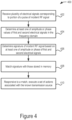
- the process 400 further includes determining a signature of the incident RF signal based on at least one of the amplitude or phase of the first and second electrical signals (406).
- the one or more processors 128 can determine a signature of the incident RF signal based on the Stokes parameters.
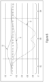
- Figure 5 shows an example chart of the values of the Stokes parameters S1[k], S2[k], and S3[k] (hereinafter referred to as S1, S2, and S3) over k frequency bins shown on the x-axis.
- the signature of the incident RF signal can be determined based on the Stokes parameters over all the k frequency bins (also referred to as "a first set of frequency bins").
- the process of transforming the incident RF signal from the time domain to the frequency domain can, in some instances, introduce artifacts in low and high frequencies in the frequency domain representation of the signal.
- the artifacts can be due to spectral leakage.
- These artifacts can be carried over to the Stokes parameters also at the high and/or low frequencies and may impact the quality of the Stokes parameters, and consequently may impact the accuracy of the signature.
- removing a group of high and/or low frequency bins can reduce the impact of those artifacts on the values of the Stokes parameters.
- the one or more processors 128 can remove 25 percent of the frequency bins, retaining 75 percent of the frequency bins for signature determination.
- the 25 percent of the removed frequency bins can be equally or unequally divided among the high and low frequency bins.
- the percentage of the total frequency bins retained can vary between 25 to 90 percent.
- the number of frequency bins in the frequency domain representation of the incident RF signal can be less than a threshold value desired for reliable signature generation.
- the one or more processors 128 can add frequency bins on one or both sides of the frequency domain representation of the incident RF signal.
- the added frequency bins can have energy levels that mirror the energy levels of the originally present adjacent frequency bins.
- At least one of the Stokes parameters can be averaged over the frequency bins.
- the one or more processors 128 can determine an average of the Stokes parameters S1, S2, and S3 over the second set of frequency bins 506.
- the one or more processors 128 can determine a fixed average of the Stokes parameters over a set of frequency bins. For example, for the first three bins, the one or more processors 128 can determine the average value of a Stokes parameter, and then assign the average value to each of the three frequency bins. The one or more processors 128 can continue in a similar manner to every subsequent set of three frequency bins until the last frequency bins is reached.
- the one or more processors 128 can carry out the same process for the other two Stokes parameters to generate average values of the stokes parameters.
- the one or more processors 128 can determine a moving average of a Stokes parameters over the frequency bins. For example, the one or more processors 128 can select a window of a number of frequency bins. At the left most position of the bin, the one or more processors 128 can assign to that frequency bin the value of the average of the frequency bins within the window. The one or more processors 128 can then move the window one frequency bin forward or backward and repeat the process until the final frequency bin is reached. Other averaging methodologies may also be used.
- Figure 6 shows example averaged Stokes parameters. The one or more processors 128 can consider the values of the averaged Stokes parameters only within the second set of frequency bins 506, as discussed above in relation to Figure 5 .
- the one or more processors 128 can determine the signature of the incident RF signal as the set the values of the Stokes parameters (shown in Figure 5 or the averaged Stokes parameter shown in Figure 6 ) within the second set of frequency bins 506.
- the one or more processors 128 store the values of the Stokes parameters in a two dimensional array, where the number of columns is equal to the number of frequency bins and the number of rows is equal to the number of Stokes parameters considered.
- a transpose of the matrix also can be stored. For example, if the second set of frequency bins is equal to 100, and the Stokes parameters include S1, S2, and S3, the one or more processors 128 can store a 3 x 100 array as the signature of the incident RF signal 112.
- the one or more processors 128 can determine the signature of the incident RF signal 112 based on curves formed on a Poincare sphere.
- the Stokes parameters S1, S2, and S3 can be treated as coordinates on a Poincare sphere, where each point on the Poincare sphere corresponds to values of the Stokes parameters in a single frequency bin. As there are several frequency bins, the values of the Stokes parameters over the several frequency bins can form a curve on the Poincare sphere surface.
- the one or more processors 128 can store the curves of known or trusted transmission sources in memory unit 126.
- the one or more processors 128 can then determine the curve on the Poincare sphere from the Stokes parameter of the incident RF signal, as discussed above.
- the one or more processors 128 can then match the curves of the incident RF signal with the curves stored in the memory unit 126 to determine if the curves match.
- the process 400 includes matching the signature of the incident RF signal with those stored in memory (408).
- the one or more processors 128 can store signatures of known or trusted transmission sources in the memory unit 126. Once the signature of the incident RF signal is determined, the one or more processors 128 can compare the signature with one or more stored signatures to determine whether the incident RF signal is from a known or trusted transmission source. In one example, determining whether the signature of the incident RF signal matches a stored signature includes determining a coefficient of correlation between the signatures.
- the one or more processors 128 can determine the coefficient of correlation between the signature of the incident RF signal and a stored signature, and if the coefficient of correlation exceeds a threshold value, the one or more processors 128 can take appropriate action.
- the correlation can be determined by determining a dot product between the signature of the incident RF signal and the stored RF signal.
- the one or more processors 128 can utilize and statistical tool to determine the correlation.
- the length of the signature of the incident RF signal can be different from the length of the stored signature.
- length can refer to the number of frequency bins (e.g., the second set of frequency bins) over which the signatures are determined.
- the one or more processors 128 can align the center frequency bin of the two signatures before performing the correlation. In some such instances, the one or more processors 128 can determine the center frequency bins based on the frequency domain representation of the signals corresponding to the signatures.
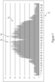
- FIG. 7 shows determining a center frequency bin in an example frequency domain representation of the incident RF signal.
- the frequency domain representation 700 shows frequency bins on the x-axis 702.
- the one or more processors 128 can determine two frequency bins having the highest energy, and determining the center frequency bin to be the frequency bin positioned between the two frequency bins and substantially equidistant from the two frequency bins. For example, the one or more processors 128 can determine a first frequency bin 704 and a second frequency bin 706 having the highest two energy levels.
- the one or more processors 128 can determine a frequency bin that is between the first frequency bin 704 and the second frequency bin 706 and that is substantially equidistant from the first frequency bin 704 and the second frequency bin 706.
- the one or more processors 128 can use this center frequency bin as a center of the signature corresponding to the signal shown in Figure 7 .
- the one or more processors 128 can similarly determine the center frequency bin of the other signature. In some instances, when storing signatures, the one or more processors 128 can store not only the signature itself, but also the determined center frequency bin.
- the one or more processors 128 can determine the center frequency bin of the incoming signature with the stored center frequency bin of the stored signature before determining the coefficient of correlation.
- the stored signatures may also be stored with associated identities of the transmission sources. Thus, if there is a match, the one or more processors 128 can readily determine the identity of the transmission source from which the incident RF signal is transmitted.
- determining a center frequency bin can be determined based on the beginning frequency bin and the end frequency bin of the main lobe of the frequency domain representation shown in Figure 7 .
- the beginning frequency bin and the end frequency bin can be determined, for example, by determining the frequency bins at which a moving average of the magnitude of the frequency domain representation goes above or falls below specified threshold values.
- the center frequency bin can then be determined as the frequency bin that is between and substantially equidistant from the beginning frequency bin and the end frequency bin.
- the coefficients of correlation generated by the correlation operation can be modified to be between the values 0 and 1, where 0 can represent no correlation, and 1 can represent a perfect match.
- the user can set a threshold value which when exceeded by the result of the correlation can indicate that the signatures match, and that the incident RF signal corresponding to the signature is from a known or trusted transmission source.
- the threshold value can be in the range of 0.8000 to 0.9999.
- the process 400 includes executing at least one action from a set of actions associated with a known transmission source in response to determining that the incident RF signal is from the known transmission source (410).
- the set of actions can include, for example, demodulating the modulated data included in the incident RF signal, annunciating at the receiver 106 that the incident RF signal is from a known transmission source, along with the identity of the known transmission source. Additionally, the set of actions can include authentication of known sources without further demodulating the signal. Additionally, the set of actions can include allowing the received signal to be transmitted to a network. Additionally, the set of actions could include alarming the presence of a known signal from critical monitoring sources. Additionally, the set of actions could include identifying the presence of persistent sources of interest, new or known.
- the one or more processors 128 can take a second set of actions, which can include, refraining from demodulating the incident RF signal, annunciating that an unknown or unauthorized transmission source has been detected, disallowing the received signal from being transmitted to a network, etc.
- the process 400 may also execute a user interface that can allow the system or a user to receive an indication of a signature match or no-match. Further, user interface can allow the system or the user to indicate to the one or more processors 128 to store the signature in the memory unit 126 even if there is no match, and in affect treat the transmission source as a trusted or known transmission source. This can allow the one or more processors 128 to build a bank of signatures of trusted or known transmission sources in the memory unit 126.
- Implementations of the subject matter and the operations described in this specification can be implemented in digital electronic circuitry, or in computer software embodied on a tangible medium, firmware, or hardware, including the structures disclosed in this specification and their structural equivalents, or in combinations of one or more of them.
- Implementations of the subject matter described in this specification can be implemented as one or more computer programs, i.e., one or more components of computer program instructions, encoded on computer storage medium for execution by, or to control the operation of, data processing apparatus.
- the program instructions can be encoded on an artificially-generated propagated signal, e.g., a machine-generated electrical, optical, or electromagnetic signal that is generated to encode information for transmission to suitable receiver apparatus for execution by a data processing apparatus.
- a computer storage medium can be, or be included in, a computer-readable storage device, a computer-readable storage substrate, a random or serial access memory array or device, or a combination of one or more of them.
- a computer storage medium is not a propagated signal, a computer storage medium can include a source or destination of computer program instructions encoded in an artificially-generated propagated signal.
- the computer storage medium can also be, or be included in, one or more separate physical components or media (e.g., multiple CDs, disks, or other storage devices).
Landscapes
- Engineering & Computer Science (AREA)
- Computer Security & Cryptography (AREA)
- Computer Networks & Wireless Communication (AREA)
- Signal Processing (AREA)
- Radar Systems Or Details Thereof (AREA)
Claims (15)
- Verfahren zum Identifizieren einfallender HF-Signale an einem Empfänger, das umfasst:Empfangen (402), über mindestens eine Antenne (116, 118), einer Vielzahl elektrischer Signale, die einem Abschnitt eines Impulses (202) eines einfallenden HF-Signals (112) entsprechen, wobei der Abschnitt des Impulses des einfallenden HF-Signals eine Dauer aufweist, die kleiner als eine Dauer eines einzelnen Impulses des einfallenden HF-Signals ist, wobei die Vielzahl elektrischer Signale ein erstes elektrisches Signal (S1u, S1v, S2u, S2v) und ein zweites elektrisches Signal (S1u, S1v, S2u, S2v) einschließen,wobei das Verfahren ferner umfasst:Transformieren des ersten elektrischen Signals und des zweiten elektrischen Signals, das in Phasenkohärenz mit dem ersten elektrischen Signal ist, in entsprechende Frequenzbereichsdarstellungen über eine Vielzahl von Frequenz-Bins (502, 504, 506);Bestimmen (404) von mindestens einem von Amplituden- oder Phasenwerten des ersten elektrischen Signals und des zweiten elektrischen Signals in Phasenkohärenz mit dem ersten elektrischen Signal aus der Vielzahl elektrischer Signale in der Vielzahl von Frequenz-Bins im Frequenzbereich;Bestimmen (406) einer Signatur des einfallenden HF-Signals basierend auf mindestens einem von einer Amplitude oder einer Phase des ersten elektrischen Signals und des zweiten elektrischen Signals in jedem der Vielzahl von Frequenz-Bins;Bestimmen, dass das einfallende HF-Signal von einer bekannten Übertragungsquelle stammt, basierend auf einer Übereinstimmung (408) zwischen der Signatur des einfallenden HF-Signals und mindestens einer Signatur, die im Speicher gespeichert ist; undAusführen (410), als Reaktion auf das Bestimmen, dass das einfallende HF-Signal von einer bekannten Übertragungsquelle stammt, mindestens einer Aktion von einem Satz von Aktionen, die der bekannten Übertragungsquelle zugeordnet sind.
- Verfahren nach Anspruch 1, wobei der Satz von Aktionen, die der bekannten Übertragungsquelle zugeordnet sind, ein Demodulieren modulierter Daten, die im einfallenden HF-Signal enthalten sind, und ein Ankündigen, am Empfänger, dass das einfallende HF-Signal von einer bekannten Übertragungsquelle stammt, einschließt.
- Verfahren nach einem der Ansprüche 1 und 2, das ferner umfasst:Entfernen von mindestens einem aus einer Gruppe von Niederfrequenz-Bins (502) oder einer Gruppe von Hochfrequenz-Bins (504) aus dem ersten Satz von Frequenz-Bins, um einen zweiten Satz von Frequenz-Bins (506) zu erzeugen; undAuswählen der Vielzahl von Frequenz-Bins, über die die Signatur des einfallenden HF-Signals bestimmt wird, als den zweiten Satz von Frequenz-Bins, wobei ein Mittenfrequenz-Bin der Vielzahl von Frequenz-Bins an einem Mittenfrequenz-Bin des ersten Satzes von Frequenz-Bins ausgerichtet ist.
- Verfahren nach einem der Ansprüche 1-3, das ferner umfasst:Bestimmen der Signatur des einfallenden HF-Signals basierend auf dem Erzeugen eines von Stokes-Parametern oder Jones-Vektoren aus mindestens einem von Amplituden- und Phasenwerten des ersten elektrischen Signals und des zweiten elektrischen Signals in jedem Frequenz-Bin der Vielzahl von Frequenz-Bins oderBestimmen der Signatur des einfallenden HF-Signals basierend auf einer Summation oder einem Durchschnitt eines von Stokes-Parametern oder Jones-Vektoren über die Vielzahl von Frequenz-Bins oderBestimmen der Signatur des einfallenden HF-Signals ferner basierend auf mindestens einem von Signalbandbreite und Polarisationskoordinaten einer Poincare-Kugel des ersten elektrischen Signals und des zweiten elektrischen Signals in jedem der Vielzahl von Frequenz-Bins.
- Verfahren nach einem der Ansprüche 1-4, wobei das Bestimmen, dass das einfallende HF-Signal von einer bekannten Übertragungsquelle stammt, basierend auf der Übereinstimmung zwischen der Signatur des einfallenden HF-Signals und der mindestens einen Signatur, die im Speicher gespeichert ist, ein Bestimmen einschließt, dass eine Korrelation zwischen der Signatur des einfallenden HF-Signals und der mindestens einen Signatur, die im Speicher gespeichert ist, einen Korrelationskoeffizienten aufweist, der größer als ein Schwellenwert ist, wobei
das Bestimmen der Korrelation zwischen der Signatur des einfallenden HF-Signals und der mindestens einen Signatur, die im Speicher gespeichert ist, ein Ausrichten eines Mittenfrequenz-Bins der Signatur des einfallenden HF-Signals und eines Mittenfrequenz-Bins der mindestens einen Signatur, die im Speicher gespeichert ist, einschließt. - Verfahren nach Anspruch 5, wobei der Mittenfrequenz-Bin der Signatur des einfallenden HF-Signals mindestens basierend auf einem Bestimmen von zwei Frequenz-Bins mit den höchsten zwei Größen im zweiten Satz von Frequenz-Bins und einem Setzen des Mittenfrequenz-Bins als einen Frequenz-Bin, der sich zwischen den zwei Frequenz-Bins befindet und im Wesentlichen äquidistant von den zwei Frequenz-Bins ist, bestimmt wird.
- Verfahren nach einem der Ansprüche 1-6, wobei die mindestens eine Antenne eine erste Antenne (116) und eine zweite Antenne (118), die räumlich von der ersten Antenne getrennt ist, einschließt, und wobei das erste elektrische Signal einer Komponente eines Signals (S1u, S1v) entspricht, das durch die erste Antenne als Reaktion auf das einfallende HF-Signal erzeugt wird, und das zweite elektrische Signal (S2u, S2v) einer Komponente eines Signals entspricht, das durch die zweite Antenne als Reaktion auf das einfallende HF-Signal erzeugt wird, oder wobei die mindestens eine Antenne eine einzelne dualpolarisierte Antenne einschließt und wobei das erste elektrische Signal und das zweite elektrische Signal polarisierten Signalkomponenten der einzelnen dualpolarisierten Antenne als Reaktion auf das einfallende HF-Signal entsprechen.
- Verfahren zum Identifizieren einfallender HF-Signale an einem Empfänger, das umfasst:
Empfangen (402), über mindestens eine Antenne (116, 118), einer Vielzahl elektrischer Signale, die einem einfallenden HF-Signal (112) entsprechen, wobei die Vielzahl elektrischer Signale ein erstes elektrisches Signal (S1u, S1v, S2u, S2v) und ein zweites elektrisches Signal (S1u, S1v, S2u, S2v) einschließen, wobei das Verfahren ferner umfasst:Transformieren des ersten elektrischen Signals und des zweiten elektrischen Signals, das in Phasenkohärenz mit dem ersten elektrischen Signal ist, in entsprechende Frequenzbereichsdarstellungen über einen ersten Satz von Frequenz-Bins (502, 504, 506);Entfernen von mindestens einem aus einer Gruppe von Niederfrequenz-Bins (502) oder einer Gruppe von Hochfrequenz-Bins (504) aus dem ersten Satz von Frequenz-Bins, um eine Vielzahl von Frequenz-Bins (506) zu erzeugen;Bestimmen (406) einer Signatur des einfallenden HF-Signals basierend auf mindestens einem von einer Amplitude oder einer Phase des ersten elektrischen Signals und des zweiten elektrischen Signals in jedem der Vielzahl von Frequenz-Bins;Bestimmen, dass das einfallende HF-Signal von einer bekannten Übertragungsquelle stammt, basierend auf einer Übereinstimmung (408) zwischen der Signatur des einfallenden HF-Signals und mindestens einer Signatur, die im Speicher gespeichert ist; undAusführen (410), als Reaktion auf das Bestimmen, dass das einfallende HF-Signal von einer bekannten Übertragungsquelle stammt, mindestens einer Aktion von einem Satz von Aktionen, die der bekannten Übertragungsquelle zugeordnet sind. - Verfahren nach Anspruch 8, wobei der Satz von Aktionen, die der bekannten Übertragungsquelle zugeordnet sind, ein Demodulieren modulierter Daten, die im einfallenden HF-Signal enthalten sind, und ein Ankündigen, am Empfänger, dass das einfallende HF-Signal von einer bekannten Übertragungsquelle stammt, einschließt.
- Verfahren nach einem der Ansprüche 8-9, wobei ein Mittenfrequenz-Bin der Vielzahl von Frequenz-Bins an einem Mittenfrequenz-Bin des ersten Satzes von Frequenz-Bins ausgerichtet ist.
- Verfahren nach einem der Ansprüche 8-10, das ferner umfasst:Bestimmen der Signatur des einfallenden HF-Signals basierend auf dem Erzeugen eines von Stokes-Parametern oder Jones-Vektoren aus mindestens einem von Amplituden- und Phasenwerten des ersten elektrischen Signals und des zweiten elektrischen Signals in jedem Frequenz-Bin der Vielzahl von Frequenz-Bins oderBestimmen der Signatur des einfallenden HF-Signals basierend auf einer Summation oder einem Durchschnitt eines von Stokes-Parametern oder Jones-Vektoren über die Vielzahl von Frequenz-Bins oderBestimmen der Signatur des einfallenden HF-Signals basierend auf mindestens einem von Signalbandbreite und Polarisationskoordinaten einer Poincare-Kugel des ersten elektrischen Signals und des zweiten elektrischen Signals in jedem der Vielzahl von Frequenz-Bins.
- Verfahren nach einem der Ansprüche 8-11, wobei das Bestimmen, dass das einfallende HF-Signal von einer bekannten Übertragungsquelle stammt, basierend auf der Übereinstimmung zwischen der Signatur des einfallenden HF-Signals und der mindestens einen Signatur, die im Speicher gespeichert ist, ein Bestimmen einschließt, dass eine Korrelation zwischen der Signatur des einfallenden HF-Signals und der mindestens einen Signatur, die im Speicher gespeichert ist, einen Korrelationskoeffizienten aufweist, der größer als ein Schwellenwert ist, wobei
das Bestimmen der Korrelation zwischen der Signatur des einfallenden HF-Signals und der mindestens einen Signatur, die im Speicher gespeichert ist, ein Ausrichten eines Mittenfrequenz-Bins der Signatur des einfallenden HF-Signals und eines Mittenfrequenz-Bins der mindestens einen Signatur, die im Speicher gespeichert ist, einschließt. - Verfahren nach Anspruch 12, wobei der Mittenfrequenz-Bin der Signatur des einfallenden HF-Signals mindestens basierend auf einem Bestimmen von zwei Frequenz-Bins mit den höchsten zwei Größen im zweiten Satz von Frequenz-Bins und einem Setzen des Mittenfrequenz-Bins als einen Frequenz-Bin, der sich zwischen den zwei Frequenz-Bins befindet und im Wesentlichen äquidistant von den zwei Frequenz-Bins ist, bestimmt wird.
- Verfahren nach einem der Ansprüche 8-13, wobei die mindestens eine Antenne eine erste Antenne (116) und eine zweite Antenne (118), die räumlich von der ersten Antenne getrennt ist, einschließt, und wobei das erste elektrische Signal einer Komponente eines Signals (S1u, S1v) entspricht, das durch die erste Antenne als Reaktion auf das einfallende HF-Signal erzeugt wird, und das zweite elektrische Signal einer Komponente eines Signals (S2u, S2v) entspricht, das durch die zweite Antenne als Reaktion auf das einfallende HF-Signal erzeugt wird, oder wobei die mindestens eine Antenne eine einzelne dualpolarisierte Antenne einschließt und wobei das erste elektrische Signal und das zweite elektrische Signal polarisierten Komponenten eines Signals der einzelnen dualpolarisierten Antenne als Reaktion auf das einfallende HF-Signal entsprechen.
- Verfahren nach einem der Ansprüche 8-14, wobei die Vielzahl elektrischer Signale einem Abschnitt eines Impulses (202) des einfallenden HF-Signals entsprechen, wobei der Abschnitt des Impulses des einfallenden HF-Signals eine Dauer aufweist, die kleiner als eine Dauer eines einzelnen Impulses des einfallenden HF-Signals ist.
Applications Claiming Priority (2)
| Application Number | Priority Date | Filing Date | Title |
|---|---|---|---|
| US202163169740P | 2021-04-01 | 2021-04-01 | |
| PCT/US2022/020955 WO2022212091A1 (en) | 2021-04-01 | 2022-03-18 | Systems and methods for radio frequency transmission source detection |
Publications (2)
| Publication Number | Publication Date |
|---|---|
| EP4315919A1 EP4315919A1 (de) | 2024-02-07 |
| EP4315919B1 true EP4315919B1 (de) | 2025-04-23 |
Family
ID=81325051
Family Applications (1)
| Application Number | Title | Priority Date | Filing Date |
|---|---|---|---|
| EP22717316.8A Active EP4315919B1 (de) | 2021-04-01 | 2022-03-18 | Systeme und verfahren zur erkennung einer funkfrequenzübertragungsquelle |
Country Status (5)
| Country | Link |
|---|---|
| US (1) | US11997485B2 (de) |
| EP (1) | EP4315919B1 (de) |
| KR (1) | KR20230164705A (de) |
| CA (1) | CA3215730A1 (de) |
| WO (1) | WO2022212091A1 (de) |
Family Cites Families (7)
| Publication number | Priority date | Publication date | Assignee | Title |
|---|---|---|---|---|
| US7120562B1 (en) * | 2003-12-17 | 2006-10-10 | L-3 Integrated Systems Company | Signal source identification utilizing wavelet-based signal processing and associated method |
| US7835319B2 (en) * | 2006-05-09 | 2010-11-16 | Cisco Technology, Inc. | System and method for identifying wireless devices using pulse fingerprinting and sequence analysis |
| US10707975B2 (en) * | 2015-04-20 | 2020-07-07 | University Of Notre Dame Du Lac | Use of coherent signal dispersion for signal source association |
| US9913139B2 (en) * | 2015-06-09 | 2018-03-06 | At&T Intellectual Property I, L.P. | Signal fingerprinting for authentication of communicating devices |
| US10605841B2 (en) | 2015-11-09 | 2020-03-31 | University Of Notre Dame Du Lac | Coherent signal analyzer |
| US12035134B2 (en) | 2018-06-19 | 2024-07-09 | University Of Notre Dame Du Lac | Security for wireless communications |
| US11218220B2 (en) | 2019-05-14 | 2022-01-04 | Infinera Corporation | Out-of-band communication channel for subcarrier-based optical communication systems |
-
2022
- 2022-03-18 EP EP22717316.8A patent/EP4315919B1/de active Active
- 2022-03-18 WO PCT/US2022/020955 patent/WO2022212091A1/en not_active Ceased
- 2022-03-18 CA CA3215730A patent/CA3215730A1/en active Pending
- 2022-03-18 KR KR1020237037173A patent/KR20230164705A/ko active Pending
- 2022-03-18 US US18/285,164 patent/US11997485B2/en active Active
Also Published As
| Publication number | Publication date |
|---|---|
| US11997485B2 (en) | 2024-05-28 |
| WO2022212091A1 (en) | 2022-10-06 |
| CA3215730A1 (en) | 2022-10-06 |
| KR20230164705A (ko) | 2023-12-04 |
| EP4315919A1 (de) | 2024-02-07 |
| US20240089733A1 (en) | 2024-03-14 |
Similar Documents
| Publication | Publication Date | Title |
|---|---|---|
| EP2575270B1 (de) | ADS-B-Empfängersystem mit Mehrwegkompensation | |
| CN110471091B (zh) | 一种基于相关器正交分量的欺骗干扰检测方法 | |
| CA2791593C (en) | Method and system for locating interference by frequency sub-band | |
| US9698987B2 (en) | Server algorithms to improve space based authentication | |
| US10594727B2 (en) | Relay attack prevention | |
| US11670848B2 (en) | Anti-jamming system | |
| US10707975B2 (en) | Use of coherent signal dispersion for signal source association | |
| US20260039411A1 (en) | Interference and jammer cancellation for radios | |
| Bao et al. | Spoofing mitigation in Global Positioning System based on C/A code self-coherence with array signal processing | |
| EP4315919B1 (de) | Systeme und verfahren zur erkennung einer funkfrequenzübertragungsquelle | |
| GB2506711A (en) | An adaptive beamformer which uses signal envelopes to correct steering | |
| JP4127250B2 (ja) | 周波数ホッピング信号検出装置及びこれを用いた電波監視システム | |
| KR20150054541A (ko) | Rfid 리더기의 수신 장치 및 수신 방법 | |
| CN117768886A (zh) | 一种基于动态超表面天线多径估计的物理层认证方法 | |
| EP3167312B1 (de) | Interferenzabschwächung für einen empfänger | |
| JP5103670B2 (ja) | 干渉が存在する状況で直線または準直線リンクを同期化させる方法および装置 | |
| Sun et al. | A self-coherence based anti-jam GPS receiver | |
| Lusk | On the Use of Uncalibrated Digital Phased Arrays for Blind Signal Separation for Interference Removal in Congested Spectral Bands | |
| Lu et al. | Novel spectrum sensing method based on the spatial spectrum for cognitive radio systems | |
| Fabrizio et al. | Exploiting multipath for blind source separation with sensor arrays | |
| Khaki et al. | Spoofing Detection and Mitigation in GNSS Using Cyclostationarity and Sparse Array | |
| Nielsen et al. | Enhanced detection of weak GNSS signals using spatial combining | |
| Hofmann et al. | Spectral Correlation for Signal Presence Detection and Frequency Acquisition of Small Satellites. Aerospace 2021, 8, 57 | |
| JP2008514080A (ja) | インパルス雑音訂正 | |
| Dhanda et al. | Performance evaluation of spectrum Sensing techniques under Noise |
Legal Events
| Date | Code | Title | Description |
|---|---|---|---|
| STAA | Information on the status of an ep patent application or granted ep patent |
Free format text: STATUS: UNKNOWN |
|
| STAA | Information on the status of an ep patent application or granted ep patent |
Free format text: STATUS: THE INTERNATIONAL PUBLICATION HAS BEEN MADE |
|
| PUAI | Public reference made under article 153(3) epc to a published international application that has entered the european phase |
Free format text: ORIGINAL CODE: 0009012 |
|
| STAA | Information on the status of an ep patent application or granted ep patent |
Free format text: STATUS: REQUEST FOR EXAMINATION WAS MADE |
|
| 17P | Request for examination filed |
Effective date: 20231016 |
|
| AK | Designated contracting states |
Kind code of ref document: A1 Designated state(s): AL AT BE BG CH CY CZ DE DK EE ES FI FR GB GR HR HU IE IS IT LI LT LU LV MC MK MT NL NO PL PT RO RS SE SI SK SM TR |
|
| DAV | Request for validation of the european patent (deleted) | ||
| DAX | Request for extension of the european patent (deleted) | ||
| GRAP | Despatch of communication of intention to grant a patent |
Free format text: ORIGINAL CODE: EPIDOSNIGR1 |
|
| STAA | Information on the status of an ep patent application or granted ep patent |
Free format text: STATUS: GRANT OF PATENT IS INTENDED |
|
| INTG | Intention to grant announced |
Effective date: 20241115 |
|
| GRAS | Grant fee paid |
Free format text: ORIGINAL CODE: EPIDOSNIGR3 |
|
| GRAA | (expected) grant |
Free format text: ORIGINAL CODE: 0009210 |
|
| STAA | Information on the status of an ep patent application or granted ep patent |
Free format text: STATUS: THE PATENT HAS BEEN GRANTED |
|
| AK | Designated contracting states |
Kind code of ref document: B1 Designated state(s): AL AT BE BG CH CY CZ DE DK EE ES FI FR GB GR HR HU IE IS IT LI LT LU LV MC MK MT NL NO PL PT RO RS SE SI SK SM TR |
|
| REG | Reference to a national code |
Ref country code: GB Ref legal event code: FG4D |
|
| REG | Reference to a national code |
Ref country code: CH Ref legal event code: EP |
|
| REG | Reference to a national code |
Ref country code: DE Ref legal event code: R096 Ref document number: 602022013570 Country of ref document: DE |
|
| REG | Reference to a national code |
Ref country code: IE Ref legal event code: FG4D |
|
| P01 | Opt-out of the competence of the unified patent court (upc) registered |
Free format text: CASE NUMBER: APP_21039/2025 Effective date: 20250502 |
|
| REG | Reference to a national code |
Ref country code: NL Ref legal event code: MP Effective date: 20250423 |
|
| PG25 | Lapsed in a contracting state [announced via postgrant information from national office to epo] |
Ref country code: NL Free format text: LAPSE BECAUSE OF FAILURE TO SUBMIT A TRANSLATION OF THE DESCRIPTION OR TO PAY THE FEE WITHIN THE PRESCRIBED TIME-LIMIT Effective date: 20250423 |
|
| REG | Reference to a national code |
Ref country code: AT Ref legal event code: MK05 Ref document number: 1789009 Country of ref document: AT Kind code of ref document: T Effective date: 20250423 |
|
| PG25 | Lapsed in a contracting state [announced via postgrant information from national office to epo] |
Ref country code: FI Free format text: LAPSE BECAUSE OF FAILURE TO SUBMIT A TRANSLATION OF THE DESCRIPTION OR TO PAY THE FEE WITHIN THE PRESCRIBED TIME-LIMIT Effective date: 20250423 Ref country code: PT Free format text: LAPSE BECAUSE OF FAILURE TO SUBMIT A TRANSLATION OF THE DESCRIPTION OR TO PAY THE FEE WITHIN THE PRESCRIBED TIME-LIMIT Effective date: 20250825 Ref country code: ES Free format text: LAPSE BECAUSE OF FAILURE TO SUBMIT A TRANSLATION OF THE DESCRIPTION OR TO PAY THE FEE WITHIN THE PRESCRIBED TIME-LIMIT Effective date: 20250423 |
|
| REG | Reference to a national code |
Ref country code: LT Ref legal event code: MG9D |
|
| PG25 | Lapsed in a contracting state [announced via postgrant information from national office to epo] |
Ref country code: NO Free format text: LAPSE BECAUSE OF FAILURE TO SUBMIT A TRANSLATION OF THE DESCRIPTION OR TO PAY THE FEE WITHIN THE PRESCRIBED TIME-LIMIT Effective date: 20250723 Ref country code: GR Free format text: LAPSE BECAUSE OF FAILURE TO SUBMIT A TRANSLATION OF THE DESCRIPTION OR TO PAY THE FEE WITHIN THE PRESCRIBED TIME-LIMIT Effective date: 20250724 |
|
| PG25 | Lapsed in a contracting state [announced via postgrant information from national office to epo] |
Ref country code: PL Free format text: LAPSE BECAUSE OF FAILURE TO SUBMIT A TRANSLATION OF THE DESCRIPTION OR TO PAY THE FEE WITHIN THE PRESCRIBED TIME-LIMIT Effective date: 20250423 |
|
| PG25 | Lapsed in a contracting state [announced via postgrant information from national office to epo] |
Ref country code: BG Free format text: LAPSE BECAUSE OF FAILURE TO SUBMIT A TRANSLATION OF THE DESCRIPTION OR TO PAY THE FEE WITHIN THE PRESCRIBED TIME-LIMIT Effective date: 20250423 |
|
| PG25 | Lapsed in a contracting state [announced via postgrant information from national office to epo] |
Ref country code: HR Free format text: LAPSE BECAUSE OF FAILURE TO SUBMIT A TRANSLATION OF THE DESCRIPTION OR TO PAY THE FEE WITHIN THE PRESCRIBED TIME-LIMIT Effective date: 20250423 |
|
| PG25 | Lapsed in a contracting state [announced via postgrant information from national office to epo] |
Ref country code: AT Free format text: LAPSE BECAUSE OF FAILURE TO SUBMIT A TRANSLATION OF THE DESCRIPTION OR TO PAY THE FEE WITHIN THE PRESCRIBED TIME-LIMIT Effective date: 20250423 |
|
| PG25 | Lapsed in a contracting state [announced via postgrant information from national office to epo] |
Ref country code: RS Free format text: LAPSE BECAUSE OF FAILURE TO SUBMIT A TRANSLATION OF THE DESCRIPTION OR TO PAY THE FEE WITHIN THE PRESCRIBED TIME-LIMIT Effective date: 20250723 |
|
| PG25 | Lapsed in a contracting state [announced via postgrant information from national office to epo] |
Ref country code: IS Free format text: LAPSE BECAUSE OF FAILURE TO SUBMIT A TRANSLATION OF THE DESCRIPTION OR TO PAY THE FEE WITHIN THE PRESCRIBED TIME-LIMIT Effective date: 20250823 |
|
| PG25 | Lapsed in a contracting state [announced via postgrant information from national office to epo] |
Ref country code: LV Free format text: LAPSE BECAUSE OF FAILURE TO SUBMIT A TRANSLATION OF THE DESCRIPTION OR TO PAY THE FEE WITHIN THE PRESCRIBED TIME-LIMIT Effective date: 20250423 |
|
| PG25 | Lapsed in a contracting state [announced via postgrant information from national office to epo] |
Ref country code: DK Free format text: LAPSE BECAUSE OF FAILURE TO SUBMIT A TRANSLATION OF THE DESCRIPTION OR TO PAY THE FEE WITHIN THE PRESCRIBED TIME-LIMIT Effective date: 20250423 Ref country code: SM Free format text: LAPSE BECAUSE OF FAILURE TO SUBMIT A TRANSLATION OF THE DESCRIPTION OR TO PAY THE FEE WITHIN THE PRESCRIBED TIME-LIMIT Effective date: 20250423 |
|
| PG25 | Lapsed in a contracting state [announced via postgrant information from national office to epo] |
Ref country code: CZ Free format text: LAPSE BECAUSE OF FAILURE TO SUBMIT A TRANSLATION OF THE DESCRIPTION OR TO PAY THE FEE WITHIN THE PRESCRIBED TIME-LIMIT Effective date: 20250423 |
|
| PG25 | Lapsed in a contracting state [announced via postgrant information from national office to epo] |
Ref country code: EE Free format text: LAPSE BECAUSE OF FAILURE TO SUBMIT A TRANSLATION OF THE DESCRIPTION OR TO PAY THE FEE WITHIN THE PRESCRIBED TIME-LIMIT Effective date: 20250423 |
|
| REG | Reference to a national code |
Ref country code: DE Ref legal event code: R097 Ref document number: 602022013570 Country of ref document: DE |
|
| PG25 | Lapsed in a contracting state [announced via postgrant information from national office to epo] |
Ref country code: SK Free format text: LAPSE BECAUSE OF FAILURE TO SUBMIT A TRANSLATION OF THE DESCRIPTION OR TO PAY THE FEE WITHIN THE PRESCRIBED TIME-LIMIT Effective date: 20250423 |
|
| PG25 | Lapsed in a contracting state [announced via postgrant information from national office to epo] |
Ref country code: IT Free format text: LAPSE BECAUSE OF FAILURE TO SUBMIT A TRANSLATION OF THE DESCRIPTION OR TO PAY THE FEE WITHIN THE PRESCRIBED TIME-LIMIT Effective date: 20250423 |
|
| PLBE | No opposition filed within time limit |
Free format text: ORIGINAL CODE: 0009261 |
|
| STAA | Information on the status of an ep patent application or granted ep patent |
Free format text: STATUS: NO OPPOSITION FILED WITHIN TIME LIMIT |
|
| REG | Reference to a national code |
Ref country code: CH Ref legal event code: L10 Free format text: ST27 STATUS EVENT CODE: U-0-0-L10-L00 (AS PROVIDED BY THE NATIONAL OFFICE) Effective date: 20260304 |
|
| 26N | No opposition filed |
Effective date: 20260126 |
|
| PGFP | Annual fee paid to national office [announced via postgrant information from national office to epo] |
Ref country code: GB Payment date: 20260316 Year of fee payment: 5 |
|
| PGFP | Annual fee paid to national office [announced via postgrant information from national office to epo] |
Ref country code: DE Payment date: 20260319 Year of fee payment: 5 |