EP4315656B1 - Verfahren, kommunikationsvorrichtung und infrastrukturausrüstung für ein nicht terrestrisches netzwerk - Google Patents
Verfahren, kommunikationsvorrichtung und infrastrukturausrüstung für ein nicht terrestrisches netzwerk Download PDFInfo
- Publication number
- EP4315656B1 EP4315656B1 EP22719583.1A EP22719583A EP4315656B1 EP 4315656 B1 EP4315656 B1 EP 4315656B1 EP 22719583 A EP22719583 A EP 22719583A EP 4315656 B1 EP4315656 B1 EP 4315656B1
- Authority
- EP
- European Patent Office
- Prior art keywords
- coverage period
- communications device
- uplink data
- ntn
- period
- Prior art date
- Legal status (The legal status is an assumption and is not a legal conclusion. Google has not performed a legal analysis and makes no representation as to the accuracy of the status listed.)
- Active
Links
Images


Classifications
-
- H—ELECTRICITY
- H04—ELECTRIC COMMUNICATION TECHNIQUE
- H04B—TRANSMISSION
- H04B7/00—Radio transmission systems, i.e. using radiation field
- H04B7/14—Relay systems
- H04B7/15—Active relay systems
- H04B7/185—Space-based or airborne stations; Stations for satellite systems
- H04B7/18502—Airborne stations
- H04B7/18504—Aircraft used as relay or high altitude atmospheric platform
-
- H—ELECTRICITY
- H04—ELECTRIC COMMUNICATION TECHNIQUE
- H04W—WIRELESS COMMUNICATION NETWORKS
- H04W72/00—Local resource management
- H04W72/12—Wireless traffic scheduling
- H04W72/1263—Mapping of traffic onto schedule, e.g. scheduled allocation or multiplexing of flows
- H04W72/1268—Mapping of traffic onto schedule, e.g. scheduled allocation or multiplexing of flows of uplink data flows
-
- H—ELECTRICITY
- H04—ELECTRIC COMMUNICATION TECHNIQUE
- H04B—TRANSMISSION
- H04B7/00—Radio transmission systems, i.e. using radiation field
- H04B7/14—Relay systems
- H04B7/15—Active relay systems
- H04B7/185—Space-based or airborne stations; Stations for satellite systems
- H04B7/1853—Satellite systems for providing telephony service to a mobile station, i.e. mobile satellite service
- H04B7/18563—Arrangements for interconnecting multiple systems
-
- H—ELECTRICITY
- H04—ELECTRIC COMMUNICATION TECHNIQUE
- H04W—WIRELESS COMMUNICATION NETWORKS
- H04W56/00—Synchronisation arrangements
- H04W56/004—Synchronisation arrangements compensating for timing error of reception due to propagation delay
- H04W56/0045—Synchronisation arrangements compensating for timing error of reception due to propagation delay compensating for timing error by altering transmission time
-
- H—ELECTRICITY
- H04—ELECTRIC COMMUNICATION TECHNIQUE
- H04W—WIRELESS COMMUNICATION NETWORKS
- H04W72/00—Local resource management
- H04W72/04—Wireless resource allocation
- H04W72/044—Wireless resource allocation based on the type of the allocated resource
- H04W72/0466—Wireless resource allocation based on the type of the allocated resource the resource being a scrambling code
-
- H—ELECTRICITY
- H04—ELECTRIC COMMUNICATION TECHNIQUE
- H04W—WIRELESS COMMUNICATION NETWORKS
- H04W72/00—Local resource management
- H04W72/20—Control channels or signalling for resource management
- H04W72/23—Control channels or signalling for resource management in the downlink direction of a wireless link, i.e. towards a terminal
- H04W72/232—Control channels or signalling for resource management in the downlink direction of a wireless link, i.e. towards a terminal the control data signalling from the physical layer, e.g. DCI signalling
-
- H—ELECTRICITY
- H04—ELECTRIC COMMUNICATION TECHNIQUE
- H04W—WIRELESS COMMUNICATION NETWORKS
- H04W84/00—Network topologies
- H04W84/02—Hierarchically pre-organised networks, e.g. paging networks, cellular networks, WLAN [Wireless Local Area Network] or WLL [Wireless Local Loop]
- H04W84/04—Large scale networks; Deep hierarchical networks
- H04W84/06—Airborne or Satellite Networks
Definitions
- the present disclosure relates generally to communications devices, infrastructure equipment and methods of operating communications devices and infrastructure equipment.
- Third and fourth generation mobile telecommunication systems such as those based on the third generation partnership project (3GPP) defined UMTS and Long Term Evolution (LTE) architectures, are able to support more sophisticated services than simple voice and messaging services offered by previous generations of mobile telecommunication systems.
- 3GPP third generation partnership project
- LTE Long Term Evolution
- a user is able to enjoy high data rate applications such as mobile video streaming and mobile video conferencing that would previously only have been available via a fixed line data connection.
- the demand to deploy such networks is therefore strong and the coverage area of these networks, i.e. geographic locations where access to the networks is possible, may be expected to increase ever more rapidly.
- NTN non-terrestrial networks
- the 3GPP has proposed in Release 15 of the 3GPP specifications to develop technologies for providing coverage by means of one or more antennas mounted on an airborne or space-borne vehicle 1 .
- Non-terrestrial networks may provide service in areas that cannot be covered by terrestrial cellular networks (i.e. those where coverage is provided by means of land-based antennas), such as isolated or remote areas, on board aircraft or vessels, or may provide enhanced service in other areas.
- the expanded coverage that may be achieved by means of non-terrestrial networks may provide service continuity for machine-to-machine (M2M) or 'internet of things' (IoT) devices, or for passengers on board moving platforms (e.g. passenger vehicles such as aircraft, ships, high speed trains, or buses).
- M2M machine-to-machine
- IoT 'internet of things'
- passengers on board moving platforms e.g. passenger vehicles such as aircraft, ships, high speed trains, or buses.
- Other benefits may arise from the use of non-terrestrial networks for providing multicast/broadcast resources for data delivery.
- NTN networks can provide improved coverage for communications devices, particularly in remote areas, a nature of communications resulting from, for example, a decrease in an amount of time which communications devices spend in a coverage area of an NTN infrastructure equipment can create new challenges that need to be addressed.
- WO 2020/231831 A1 (APPLE INC [US]), published on 19 November 2020 , discusses slot offset determination for non-terrestrial networks.
- the present disclosure can help address or mitigate at least some of the issues discussed above.
- a method of operating a communications device to transmit or to receive via a wireless communications network including non-terrestrial, NTN, infrastructure equipment identifies a first in-coverage period during which the communications device can transmit signals to or receive signals from a first NTN infrastructure equipment, the first NTN infrastructure equipment being either carried by a first aerial vehicle or relayed via the first aerial vehicle to or from the first NTN infrastructure equipment as the aerial vehicle passes over the communications device.
- the communications device identifies a second in-coverage period during which the communications device can transmit signals to or receive signals from either the first NTN infrastructure equipment or a second NTN infrastructure equipment, the second NTN infrastructure equipment being either carried by a second aerial vehicle or the transmitted or the received signal are relayed via the second aerial vehicle to or from the second NTN infrastructure equipment as the second aerial vehicle passes over the communications device.
- the communications device transmits uplink data to the wireless communications network by adapting a transmission of the uplink data to include at least part of the second in-coverage period, based on a length of time required to transmit the uplink data and a start time at which the uplink data can be transmitted in the first in-coverage period with respect to an end of the first in-coverage period, or alternatively, the communications device receives downlink data from the wireless communications network by adapting a reception of the downlink data to include at least part of the second in-coverage period, having been transmitted at least partly in the second in-coverage period, based on a length of time required to receive the downlink data and a start time at which the downlink data can be received in the first in-coverage period with respect to an end of the first in-coverage period.
- Example embodiments can provide a communications device, which is identifies that an uplink transmission or a downlink reception has a time duration which will exceed a time for which the communications device remains in a current in-coverage period but can be continued in a subsequent in-coverage period provided by either the same NTN infrastructure equipment or another NTN infrastructure equipment.
- Example embodiments can find application with repeated transmission/received of the same transport block to improve a likelihood of correct communication, which can exceed a remaining duration of an in-coverage period in which the transmission/reception is scheduled.
- Figure 1 provides a schematic diagram illustrating some basic functionality of a mobile telecommunications network / system 100 operating generally in accordance with LTE principles, but which may also support other radio access technologies, and which may be adapted to implement embodiments of the disclosure as described herein.
- Various elements of Figure 1 and certain aspects of their respective modes of operation are well-known and defined in the relevant standards administered by the 3GPP (RTM) body, and also described in many books on the subject, for example, Holma H. and Toskala A [2].
- the network 100 includes a plurality of base stations 101 connected to a core network part 102.
- Each base station provides a coverage area 103 (e.g. a cell) within which data can be communicated to and from communications devices 104.
- Data is transmitted from the base stations 101 to the communications devices 104 within their respective coverage areas 103 via a radio downlink.
- Data is transmitted from the communications devices 104 to the base stations 101 via a radio uplink.
- the core network part 102 routes data to and from the communications devices 104 via the respective base stations 101 and provides functions such as authentication, mobility management, charging and so on.
- Communications devices may also be referred to as mobile stations, user equipment (UE), user terminals, mobile radios, terminal devices, and so forth.
- Base stations which are an example of network infrastructure equipment / network access nodes, may also be referred to as transceiver stations / nodeBs / e-nodeBs (eNB), g-nodeBs (gNB) and so forth.
- eNB e-nodeB
- gNB g-nodeB
- different terminology is often associated with different generations of wireless telecommunications systems for elements providing broadly comparable functionality.
- example embodiments of the disclosure may be equally implemented in different generations of wireless telecommunications systems such as 5G or new radio as explained below, and for simplicity certain terminology may be used regardless of the underlying network architecture. That is to say, the use of a specific term in relation to certain example implementations is not intended to indicate these implementations are limited to a certain generation of network that may be most associated with that particular terminology.
- FIG. 2 is a schematic diagram illustrating a network architecture for a new RAT wireless communications network / system 200 based on previously proposed approaches which may also be adapted to provide functionality in accordance with embodiments of the disclosure described herein.
- the new RAT network 200 represented in Figure 2 comprises a first communication cell 201 and a second communication cell 202.
- Each communication cell 201, 202 comprises a controlling node (centralised unit) 221, 222 in communication with a core network component 210 over a respective wired or wireless link 251, 252.
- the respective controlling nodes 221, 222 are also each in communication with a plurality of distributed units (radio access nodes / remote transmission and reception points (TRPs)) 211, 212 in their respective cells.
- TRPs remote transmission and reception points
- the distributed units (DUs) 211, 212 are responsible for providing the radio access interface for communications devices connected to the network.
- Each distributed unit 211, 212 has a coverage area (radio access footprint) 241, 242 where the sum of the coverage areas of the distributed units under the control of a controlling node together define the coverage of the respective communication cells 201, 202.
- Each distributed unit 211, 212 includes transceiver circuitry for transmission and reception of wireless signals and processor circuitry configured to control the respective distributed units 211, 212.
- the core network component 210 of the new RAT communications network represented in Figure 2 may be broadly considered to correspond with the core network 102 represented in Figure 1 , and the respective controlling nodes 221, 222 and their associated distributed units / TRPs 211, 212 may be broadly considered to provide functionality corresponding to the base stations 101 of Figure 1 .
- the term network infrastructure equipment / access node may be used to encompass these elements and more conventional base station type elements of wireless communications systems.
- the responsibility for scheduling transmissions which are scheduled on the radio interface between the respective distributed units and the communications devices may lie with the controlling node / centralised unit and / or the distributed units / TRPs.
- a communications device or UE 260 is represented in Figure 2 within the coverage area of the first communication cell 201. This communications device 260 may thus exchange signalling with the first controlling node 221 in the first communication cell via one of the distributed units 211 associated with the first communication cell 201. In some cases communications for a given communications device are routed through only one of the distributed units, but it will be appreciated in some other implementations communications associated with a given communications device may be routed through more than one distributed unit, for example in a soft handover scenario and other scenarios.
- two communication cells 201, 202 and one communications device 260 are shown for simplicity, but it will of course be appreciated that in practice the system may comprise a larger number of communication cells (each supported by a respective controlling node and plurality of distributed units) serving a larger number of communications devices.
- Figure 2 represents merely one example of a proposed architecture for a new RAT communications system in which approaches in accordance with the principles described herein may be adopted, and the functionality disclosed herein may also be applied in respect of wireless communications systems having different architectures.
- example embodiments of the disclosure as discussed herein may be implemented in wireless telecommunication systems / networks according to various different architectures, such as the example architectures shown in Figures 1 and 2 . It will thus be appreciated the specific wireless communications architecture in any given implementation is not of primary significance to the principles described herein. In this regard, example embodiments of the disclosure may be described generally in the context of communications between network infrastructure equipment / access nodes and a communications device, wherein the specific nature of the network infrastructure equipment / access node and the communications device will depend on the network infrastructure for the implementation at hand.
- the network infrastructure equipment / access node may comprise a base station, such as an LTE-type base station 101 as shown in Figure 1 which is adapted to provide functionality in accordance with the principles described herein, and in other examples the network infrastructure equipment / access node may comprise a control unit / controlling node 221, 222 and / or a TRP 211, 212 of the kind shown in Figure 2 which is adapted to provide functionality in accordance with the principles described herein.
- a base station such as an LTE-type base station 101 as shown in Figure 1 which is adapted to provide functionality in accordance with the principles described herein
- the network infrastructure equipment / access node may comprise a control unit / controlling node 221, 222 and / or a TRP 211, 212 of the kind shown in Figure 2 which is adapted to provide functionality in accordance with the principles described herein.
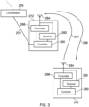
- FIG. 3 A more detailed illustration of a communications device 270 and an example network infrastructure equipment 272, which may be thought of as an eNB or a gNB 101 or a combination of a controlling node 221 and TRP 211, is presented in Figure 3 .
- the communications device 270 is shown to transmit uplink data to the infrastructure equipment 272 of a wireless access interface as illustrated generally by an arrow 274.
- the UE 270 is shown to receive downlink data transmitted by the infrastructure equipment 272 via resources of the wireless access interface as illustrated generally by an arrow 288.
- the infrastructure equipment 272 is connected to a core network 276 (which may correspond to the core network 102 of Figure 1 or the core network 210 of Figure 2 ) via an interface 278 to a controller 280 of the infrastructure equipment 272.
- the infrastructure equipment 272 may additionally be connected to other similar infrastructure equipment by means of an inter-radio access network node interface, not shown on Figure 3 .
- the infrastructure equipment 272 includes a receiver 282 connected to an antenna 284 and a transmitter 286 connected to the antenna 284.
- the communications device 270 includes a controller 290 connected to a receiver 292 which receives signals from an antenna 294 and a transmitter 296 also connected to the antenna 294.
- the controller 280 is configured to control the infrastructure equipment 272 and may comprise processor circuitry which may in turn comprise various sub-units / sub-circuits for providing functionality as explained further herein. These sub-units may be implemented as discrete hardware elements or as appropriately configured functions of the processor circuitry. Thus the controller 280 may comprise circuitry which is suitably configured / programmed to provide the desired functionality using conventional programming / configuration techniques for equipment in wireless telecommunications systems.
- the transmitter 286 and the receiver 282 may comprise signal processing and radio frequency filters, amplifiers and circuitry in accordance with conventional arrangements.
- the transmitter 286, the receiver 282 and the controller 280 are schematically shown in Figure 3 as separate elements for ease of representation.
- the functionality of these elements can be provided in various different ways, for example using one or more suitably programmed programmable computer(s), or one or more suitably configured application-specific integrated circuit(s) / circuitry / chip(s) / chipset(s).
- the infrastructure equipment 272 will in general comprise various other elements associated with its operating functionality.
- the controller 290 of the communications device 270 is configured to control the transmitter 296 and the receiver 292 and may comprise processor circuitry which may in turn comprise various sub-units / sub-circuits for providing functionality as explained further herein. These sub-units may be implemented as discrete hardware elements or as appropriately configured functions of the processor circuitry.
- the controller 290 may comprise circuitry which is suitably configured / programmed to provide the desired functionality using conventional programming / configuration techniques for equipment in wireless telecommunications systems.
- the transmitter 296 and the receiver 292 may comprise signal processing and radio frequency filters, amplifiers and circuitry in accordance with conventional arrangements.
- the transmitter 296, receiver 292 and controller 290 are schematically shown in Figure 3 as separate elements for ease of representation.
- the functionality of these elements can be provided in various different ways, for example using one or more suitably programmed programmable computer(s), or one or more suitably configured application-specific integrated circuit(s) / circuitry / chip(s) / chipset(s).
- the communications device 270 will in general comprise various other elements associated with its operating functionality, for example a power source, user interface, and so forth, but these are not shown in Figure 3 in the interests of simplicity.
- the controllers 280, 290 may be configured to carry out instructions which are stored on a computer readable medium, such as a non-volatile memory.
- a computer readable medium such as a non-volatile memory.
- the processing steps described herein may be carried out by, for example, a microprocessor in conjunction with a random access memory, which may be non-volatile memory, operating according to instructions stored on a computer readable medium.
- NTNs Non-Terrestrial Networks
- an aerial vehicle may allow a connection of a communications device and a ground station (which may be referred to herein as an NTN gateway).
- the term aerial vehicle is used to refer to a space vehicle, aerial platform, or satellite, or any other entity which moves relative to a communications device and is configured to communicate with the communications device.
- an aerial vehicle may be in some embodiments a low earth orbit (LEO) satellite, a medium earth orbit (MEO) satellite, a high altitude platform system (HAPS), a balloon or a drone for example.
- LEO low earth orbit
- MEO medium earth orbit
- HAPS high altitude platform system
- the aerial vehicle is configured to communicate with the communications device and the ground station of a terrestrial network by means of non-communications circuitry of the aerial vehicle.
- Non-Terrestrial Networks are expected to:
- Non-Terrestrial Networks operating alone or to integrated terrestrial and Non-Terrestrial networks. They will impact at least coverage, user bandwidth, system capacity, service reliability or service availability, energy consumption and connection density.
- a role for Non-Terrestrial Network components in the 5G system is expected for at least the following verticals: transport, Public Safety, Media and Entertainment, eHealth, Energy, Agriculture, Finance and Automotive.
- transport Public Safety, Media and Entertainment, eHealth, Energy, Agriculture, Finance and Automotive.
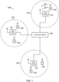
- FIG 4 schematically shows an example of a wireless communications system 300 which may be configured to operate in accordance with embodiments of the present disclosure.
- the wireless communications system 300 in this example is based broadly around an LTE-type or NR-type architecture.
- wireless communications system / network 300 Many aspects of the operation of the wireless communications system / network 300 are known and understood and are not described here in detail in the interest of brevity. Operational aspects of the wireless communications system 300 which are not specifically described herein may be implemented in accordance with any known techniques, for example according to the current LTE-standards or the proposed NR standards.
- An aerial vehicle 310 includes communications circuitry 334.
- the communications circuitry 334 may be non-terrestrial infrastructure equipment which is mounted on, and/or within the aerial vehicle 310 as explained below.
- the communications circuitry 334 communicates via the ground station 330 with the base station 332 via a wireless communications link 312.
- the communications circuitry 334 may communicate with a communications device 306, located within a cell 308, by means of a wireless access interface provided by a wireless communications link 314.
- the cell 308 may correspond to the coverage area of a spot beam generated by the communications circuitry 334.
- the boundary of the cell 308 may depend on an altitude of the aerial vehicle 310 and a configuration of one or more antennas of the communications circuitry 334 by which the aerial vehicle transmits and receives signals on the wireless access interface.
- the spot beam may be an "earth fixed beam" which illuminates a geographic area on a surface of the earth for a pre-defined period of time. After the pre-defined period of time, the earth fixed beam may switch to serving a different geographic area on the surface of the earth.
- the aerial vehicle 310 may be a satellite in an orbit with respect to the Earth.
- the satellite may be in a non-geostationary orbit (NGSO), so that the aerial vehicle 310 moves with respect to a fixed point on the Earth's surface.
- NGSO non-geostationary orbit
- An example of an NGSO is an LEO, in which the satellite may complete an orbit of the Earth relatively quickly, thus providing moving cell coverage.
- the ground station 330 is connected to the communications circuitry 334 by means of a wireless communications link 312.
- the communications circuitry 334 receives signals representing downlink data transmitted by the radio access network 301 on the wireless communications link 312 and, based on the received signals, transmits signals representing the downlink data via the wireless communications link 314 providing the wireless access interface for the communications device 306.
- the communications circuitry 334 receives signals representing uplink data transmitted by the communications device 306 via the wireless access interface comprising the wireless communications link 314 and transmits signals representing the uplink data to the ground station 330 on the wireless communications link 312.
- the wireless communications links 312, 314 may operate at a same frequency, or may operate at different frequencies.
- the extent to which the communications circuitry 334 processes the received signals may depend upon a processing capability of the communications circuitry 334.
- the communications circuitry 334 may receive signals representing the downlink data on the wireless communication link 312, amplify them and (if needed) re-modulate onto an appropriate carrier frequency for onwards transmission on the wireless access interface provided by the wireless communications link 314.
- Figure 5 illustrates an example of an NTN architecture based on communications circuitry of an aerial vehicle operating in a transparent manner, meaning that a signal received from the communications device at the aerial vehicle is forwarded (to the communications device, to a ground station on Earth or to another aerial vehicle) with only frequency conversion and/or amplification.
- a wireless access interface (such as a 5G Uu interface) may be generated at a base station located on the Earth, and connects the base station (gNB, in the example of Figure 5 ) and the communications device (UE).
- the base station may be regarded as a non-terrestrial infrastructure equipment, and communications are relayed between the non-terrestrial infrastructure equipment and the communications device 306.
- the communications circuitry 334 of the aerial vehicle 310 may be configured to decode the signals representing the downlink data received on the wireless communication link 312 into un-encoded downlink data, re-encode the downlink data and modulate the encoded downlink data onto the appropriate carrier frequency for onwards transmission on the wireless access interface provided by the wireless communications link 314.
- the communications circuitry 334 may be configured to perform some of the functionality conventionally carried out by a base station (e.g. a gNodeB or an eNode B), such as base station 101 of Figure 1 .
- a base station e.g. a gNodeB or an eNode B
- latency-sensitive functionality such as acknowledging a receipt of the uplink data, or responding to a RACH request
- the communications circuitry 334 of the aerial vehicle 310 may be regarded as a non-terrestrial infrastructure equipment.
- a physical (e.g. wired, or fibre optic) connection on board the aerial vehicle 310 which provides the coupling between the circuitry of the communications circuitry 334 which implements base station functionality and a transceiver of the communications circuitry 334 which is configured communicate with the communications device 306 and the ground station 330.
- a wireless communications feeder link between the communications circuitry 334 and the ground station 330 may provide connectivity between the communications circuitry 334 and the core network part 302.
- the base station 332 may not be present.
- Figure 6 illustrates an example of an NTN architecture based on communications circuitry equipment of an aerial vehicle implementing at least some base station functionality.
- the communications circuitry 334 is an example of non-terrestrial infrastructure equipment.
- the communications circuitry 334 generates the wireless access interface (e.g. the Uu interface) which connects the aerial vehicle and the communications device.
- the communications circuitry may decode a received signal, and encode and generate a transmitted signal.
- the non-communications circuitry may include some or all of the functionality of a base station (such as a gNodeB or eNodeB).
- a further connection between the communications circuitry 334 and a ground station (such as an NTN gateway) may be by means of a separate wireless access interface, and may form part of a connection between the communications circuitry 334 and a core network.
- the communications device 306 shown in Figure 4 may be configured to act as a relay node. That is, it may provide connectivity to one or more terminal devices such as the terminal device 304. When acting as a relay node, the communications device 306 transmits and receives data to and from the terminal device 304, and relays it, via the aerial vehicle 310 to the ground station 330. The communications device 306, acting as a relay node, may thus provide connectivity to the core network part 302 for terminal devices which are within a transmission range of the communications device 306.
- the communications device 306 may be mounted on a passenger vehicle such as a bus or train, which travels through rural areas where coverage by terrestrial base stations may be limited. Terminal devices on the vehicle may obtain service via the communications device 306 acting as a relay, which communicates with the communications circuitry 334.
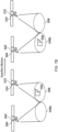
- the communications circuitry 334 of the aerial vehicle 310 may comprise a plurality of antennae configured to generate a corresponding plurality of spot beams.
- Each of the plurality of spot beams may illuminate a different area of the Earth's surface to provide a plurality of cells 308, 348a each corresponding to a coverage area of one of the plurality of spot beams.
- the aerial vehicle 310 may communicate with a communications device (such as communications device 306) located in any one of the plurality of cells 308, 348a provided by the plurality of spot beams by means of a wireless access interface provided by a wireless communications link (such as wireless communications link 314) to the communications device.
- the boundary of each of the plurality of cells may depend on an altitude of the aerial vehicle 310 and a configuration of the plurality of antennae of the aerial vehicle 310 by which the aerial vehicle 310 transmits and receives signals on the wireless access interface.
- the communications device 306 may move from the coverage area 308 of a first beam generated by the communications circuitry 334 carried by the aerial vehicle 310 to the coverage area 348a of a second beam generated by the communications circuitry 334 carried by the aerial vehicle 310.
- the communications device 306 may be handed over from the coverage area 308 of the first beam to the coverage area 348a of the second beam.
- the communications device 306 may be configured to receive coverage from a plurality of aerial vehicles 310, 360 each including respective communications circuitry 334, 384.
- the communications circuitry 334 of a first 310 of the plurality of aerial vehicles may generate a first beam defining a coverage area 308.
- the communications circuitry of a second 310 of the plurality of aerial vehicles may generate a second beam defining a coverage area 348b.
- the communications device 306 may move from the coverage area 308 of the first beam generated by the first aerial vehicle 310 to the coverage area 348b of the second beam generated by the second aerial vehicle 360. In other words, the communications device 306 may be handed over from the coverage area 308 of the first beam to the coverage area 348b of the second beam.
- the reference numeral "348” is to be taken to mean either coverage area 348a or coverage area 348b and the phrase "second beam” is to be taken as referring to either the second beam as explained with respect to Figure 7A or Figure 7B .
- An "in-coverage period of the first beam” and an “in-coverage period of the second beam” are taken to mean a time period which a communications device spends in the coverage area 308 defined by the first beam and the coverage area 348 defined by the second beam respectively.
- each of the plurality of cells has a different Physical Cell Identity (PCI). Accordingly, reference signals and scrambling codes used may be different for each of the plurality of cells, and each of the plurality of cells may be scheduled independently of each other.
- a handover of the communications device 306 from the coverage area 308 of the first beam to the coverage area 348 of the second beam may consist of a connected mode handover, a cell selection procedure or a cell reselection procedure.
- the handover procedure may be controlled by measurements made by the communications device and communicated to the base station, controlled by measurements made by the base station, controlled by declaration of radio link failure by the communications device or by other means.
- a decision to change a serving cell of the communications device 306 may be based on measurements of one or more characteristics of a radio frequency communications channel, such as signal strength measurements or signal quality measurements.
- a radio frequency communications channel such as signal strength measurements or signal quality measurements.
- such measurements may effectively provide an indication that the communications device 306 is at, or approaching, an edge of a coverage region of a cell, since, for example, path loss may broadly correlate to a distance from a base station.
- path loss may broadly correlate to a distance from a base station.
- such conventional measurement-based algorithms may be unsuitable for cells generated by means of the transmission of beams from communications circuitry 334 of an aerial vehicle, such as the cell 308 generated by the aerial vehicle 310.
- a further challenge of conventional techniques may be the relatively high rate at which cell changes occur for the communications device 306 obtaining service from one or more aerial vehicles.
- the aerial vehicle 310 is an LEO satellite
- the aerial vehicle 310 may complete an orbit of the Earth in around 90 minutes; the coverage of a cell generated by the aerial vehicle 310 will move very rapidly, with respect to a fixed observation point on the surface of the Earth (in one example, an LEO may move at 7.56 km/s as explained above).
- the communications device 306 may be mounted on an airborne vehicle itself, typically having a ground speed of several hundreds of kilometres per hour.
- a speed of the aerial vehicle 310 relative to a fixed point on the Earth is generally much larger than typical speeds of airborne vehicles configured to mount the communications device 306.
- NTNs One particular difficulty associated with NTNs is the large distances and relative speeds between a UE (such as communications device 306) and an eNB (such as base station 332 or a base station implemented in the communications circuitry 334) compared to terrestrial networks.
- a UE such as communications device 306
- an eNB such as base station 332 or a base station implemented in the communications circuitry 33
- the distance between the satellite and the UE may be between 600km to 1200km.
- the propagation delay between the UE hereinafter the term UE is used to refer to any communications device configured to communicate with a non-terrestrial infrastructure equipment of an NTN
- the eNB is significantly larger than for terrestrial networks, particularly in a 'transparent' arrangement such as that shown in Figure 5 .
- the Round Trip Time (RTT) between the UE and the eNB may be between approximately 8ms to approximately 26 ms [3].
- Timing Advance In order to take into account this large propagation delay, uplink transmissions would need to apply a large Timing Advance (TA) and the eNB would need to take this into account for scheduling of uplink data.
- the timing advance that needs to be applied depends on the location of the UE within the cell footprint of the satellite. Since the cell footprint can be large, there can be a large variation of the timing advance that needs to be applied, depending on the UE location within the cell footprint.
- the NTN system In addition to the increased RTT between the UE and the eNB, the NTN system also needs to take into account the movement of the satellite. For example, a LEO satellite can be travelling at 7.56 km/second (27,216 km/h) relative to the UE, which would cause significant Doppler shift that the UE needs to compensate for. In order to factor in the Doppler shift, i.e. in order to apply a pre-compensation for the frequency of the uplink transmissions, the UE needs to know its own geo-location and the motion (e.g. position and velocity) of the satellite.
- the geo-location of the UE can, for example, be obtained from a Global Navigation Satellite System (GNSS) or from any other suitable means.
- GNSS Global Navigation Satellite System
- the position and velocity of the satellite can be derived from the satellite ephemeris information, that is the satellite orbital trajectory, which can be periodically broadcast to the UE, e.g. via System Information Blocks (SIBs).
- SIBs System Information Blocks
- broadcasting ephemeris information e.g. every 100ms, can lead to high signaling overhead.
- signaling ephemeris information does not take into account perturbations in the satellite orbit and hence may not provide sufficient accuracy to determine the required timing advance and frequency compensation.
- satellites in LEO do not exist in a perfect vacuum and thus experience a number of factors such as varying drag coefficients or gravitational forces which perturb the orbit of the satellite.
- the accuracy with which the UE can accurately determine the position and velocity of the satellite decreases.
- the eNB or an NTN Gateway can derive the satellite position and velocity and broadcast it via the SIBs.
- the satellite position and velocity may be determined by the eNB or NTN Gateway, for example, via GNSS or other suitable means.
- the eNB or NTN Gateway may determine the satellite position and velocity via communications on the network itself, or the eNB or NTN Gateway may determine the satellite position and velocity by other means, separate from the network.
- the eNB or NTN Gateway may derive the satellite position and velocity, e.g. via a telemetry link to the satellite, and the eNB may transmit that information in the SIBs.
- NTNs compared to terrestrial networks lead to technical challenges.
- Another associated difficulty for NTNs compared to terrestrial networks is that the UE spends a relatively short time in a coverage area of the cell compared to terrestrial networks.
- the time which a UE spends in the coverage area of a cell for NTNs depends on a distance between the UE and a satellite (which may or may not be co-located with the eNB as explained above), a speed of the UE relative to the satellite and a width of a spot beam generated by the satellite which provides the coverage area.
- an LEO orbiting the Earth at an altitude of 600km and generating a spot beam operating at a carrier frequency of 2 GHz may have an 3dB angular beamwidth of 4.4127 degrees (corresponding to a 46 km beamwidth when the LEO is at its zenith) [3].
- the UE will be in the coverage area of the spot beam for only 6.1 seconds.
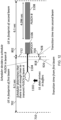
- the base station may schedule the communications device 306 to transmit signals representing uplink data during the in-coverage period 702 in the form of a Physical Uplink Shared Channel (PUSCH) transmission with an associated transmission period.
- the transmission period of a PUSCH transmission is the time taken for a complete PUSCH transmission.
- the transmission period for a PUSCH transmission can be up to 4.096 seconds, where the maximum transmission period of the PUSCH can be determined by the eNB scheduler up to a maximum value supported in the NB-IoT specifications.
- an early PUSCH transmission 704 and a late PUSCH transmission 706 are the earliest and latest respective PUSCH transmissions which can be completely transmitted in the in-coverage period 702.
- a start point 710 of the in-coverage period 702 coincides with a start point of the scheduling window 708 and a start point of the early PUSCH transmission 704.
- An end point 712 of the in-coverage period coincides with an end point of the late PUSCH transmission 706.
- An end point 714 of the scheduling window 702 coincides with a start point of the late PUSCH transmission 706. It will be appreciated that, in the example provided in Figure 8 , a length of the scheduling window is provided by a difference between a length of the in-coverage period 702 (6.1 seconds) and the transmission period (4.096 seconds). Accordingly, in the example provided in Figure 8 , the length of the scheduling window 708 is approximately two seconds.
- a PUSCH transmission must be scheduled to begin within the approximately two second scheduling window 708 in order to ensure complete PUSCH transmission. If a PUSCH transmission is scheduled to begin later than the scheduling window 708 then the PUSCH transmission may not be able to be completely transmitted within the in-coverage period 702.
- Figure 8 is a simplified representation of examples of scheduled communications resources in time and frequency space for transmitting uplink data from the communications device 306 to the aerial vehicle 310 while the communications device 306 is in the coverage area 308 of a beam generated by the aerial vehicle 310.
- Figure 9 is based on Figure 8 and additionally accounts for transition times for the communications device 306 to enter and leave the coverage area 308 of the beam.
- the communications device 306 leaves the coverage area 308 of the beam, which is a first beam, it may enter a coverage area of another, second beam (such as coverage area 348).
- the second beam may be generated by an antenna of the aerial vehicle 310 which provides the first beam or, alternatively, by an antenna of another aerial vehicle (such as aerial vehicle 360).
- a portion of the in-coverage period 702 may be occupied by a time taken for the communications device to transition into the coverage area 308 of the first beam (referred to as "entering period 716") and a time taken for the communications device 306 to transition out of the coverage area 308 of the first beam (referred to as “leaving period 818").
- Communications resources in the entering period 716 may be reserved for various communications processes as the communications device 306 enters the coverage area 308 of the first beam.
- the communications device 306 may:
- communications resources in the leaving period 818 may be reserved for various communications processes as the communications device 306 moves out of the coverage area of the first beam.
- the communications device 306 may:
- Figure 9 shows an early PUSCH transmission 804 and a late PUSCH transmission 806 which are the earliest and latest respective PUSCH transmissions which can be completely transmitted in the in-coverage period 702 when the entering period 716 and the leaving period 818 are accounted for.
- a PUSCH transmission may be completely transmitted if it is scheduled to begin at any time during a scheduling window 808 of the in-coverage period 702.
- a start point 810 of the scheduling window 808 coincides with a start point of the early PUSCH transmission 804.
- An end point 814 of the scheduling window 808 coincides with a start point of the late PUSCH transmission 806.
- a start point of the leaving period 818 coincides with an end point of the late PUSCH transmission 812.
- a length of the scheduling window is provided by a difference between a length of the in-coverage period 702 (6.1 seconds) and the transmission period (4.096 seconds), less the entering period 716 and the leaving period 818. Accordingly, in the example provided in Figure 9 , the length of the scheduling window 808 is less than the scheduling window 708 in Figure 8 .
- a PUSCH transmission must be scheduled to begin within the less than two second scheduling window 808 in order to ensure complete PUSCH transmission. If a PUSCH transmission is scheduled to begin later than the scheduling window 808 then the PUSCH transmission may not be able to be completely transmitted.
- An NB-IoT transmission spanning 4.096 seconds is referred to in the present disclosure as consisting of 4096 repetitions. It will be appreciated that references to "repetitions" may consist of a mixture of resource units and actual repetitions.
- references to "repetitions" may consist of a mixture of resource units and actual repetitions.
- the present disclosure refers to eMTC transmissions of 4.096 seconds duration or of 4096 repetitions, it will be appreciated by one skilled in the art that this is merely an example and other durations/number of repetitions may be used. While the maximum number of eMTC transmissions in a current standard is 2048 repetitions, it will be appreciated that the following description refers to eMTC transmissions of 4.096 second duration as this acts to highlight the nature of the problem to be solved. It will further be appreciated that embodiments discussed below with respect to eMTC may be applied to NB-IoT. In NB-IoT, transmissions of duration 4.096 seconds are possible according to the current standards.
- a method of operating a communications device to transmit or to receive via a wireless communications network including non-terrestrial, NTN, infrastructure equipment identifies a first in-coverage period during which the communications device can transmit signals to or receive signals from a first NTN infrastructure equipment, the first NTN infrastructure equipment being either carried by a first aerial vehicle or relayed via the first aerial vehicle to or from the first NTN infrastructure equipment as the aerial vehicle passes over the communications device.
- the communications device identifies a second in-coverage period during which the communications device can transmit signals to or receive signals from either the first NTN infrastructure equipment or a second NTN infrastructure equipment, the second NTN infrastructure equipment being either carried by a second aerial vehicle or the transmitted or the received signal are relayed via the second aerial vehicle to or from the second NTN infrastructure equipment as the second aerial vehicle passes over the communications device.
- the communications device transmits uplink data to the wireless communications network by adapting a transmission of the uplink data to include at least part of the second in-coverage period, based on a length of time required to transmit the uplink data and a start time at which the uplink data can be transmitted in the first in-coverage period with respect to an end of the first in-coverage period, or alternatively, the communications device receives downlink data from the wireless communications network by adapting a reception of the downlink data to include at least part of the second in-coverage period, having been transmitted at least partly in the second in-coverage period, based on a length of time required to receive the downlink data and a start time at which the downlink data can be received in the first in-coverage period with respect to an end of the first in-coverage period.
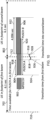
- FIG 10 illustrates an example of the communications device 306 deferring an uplink transmission according to example embodiments.
- the communications device 306 receives an MTC PDCCH (MPDCCH) transmission 902 while in the coverage period 702 of the first beam.
- the MPDCCH transmission 902 informs the communications device 306 that it has been scheduled to transmit a PUSCH transmission 904.
- the scheduled PUSCH transmission 904 cannot be completely transmitted before the communications device 306 moves out of the coverage area 308 of the first beam.
- an available time period 918 for transmission is less than a transmission time period for the scheduled PUSCH transmission 904.
- a start point 924 of the available time period 918 coincides with a start point of the scheduled PUSCH transmission 904 and an end point 926 of the available time period 918 coincides with a start point of the leaving period 818 for the first beam. Since the available time period 918 is shorter than the transmission time period 920 for the scheduled PUSCH 904, the scheduled PUSCH cannot be completely transmitted in the in-coverage period 702 of the first beam.
- the communications device 306 may determine that the scheduled PUSCH 904 cannot be completely transmitted in the in-coverage period 702 of the first beam. In response, the communications device 306 may determine to defer transmission of the scheduled PUSCH 904 until the communications device 306 is in the coverage area 348 of the second beam. In example embodiments, the communications device 306 may defer the transmission of the scheduled PUSCH 904 to begin at an end point 928 of an entering period 916 for the second beam, as shown by the deferred PUSCH 906 in Figure 10 .
- the communications device 306 may prepare for transition into the coverage area 348 of the second beam by performing a synchronisation process, performing measurements and/or executing a Random Access Channel (RACH) process in the second beam for example.
- RACH Random Access Channel
- a length of the entering period 916 for the second beam may be known by both the communications device 306 and the base station which schedules the communications device 306.
- the length of the entering period 916 may be represented as a number of subframes ( N trans ) after a start point of the in-coverage period 802 of the second beam (which coincides with the end point of the in-coverage period 702 of the first beam in Figure 10 ).
- the value of N trans may be defined in specifications, signalled explicitly to the communications device 306 by the base station in Downlink Control Information (DCI) or signalled by other means.
- DCI Downlink Control Information
- the value of N trans may be a function of a coverage level of the communications device 306 in which case the communications device 306 may be aware of a mapping between the coverage level and N trans , and use the mapping to determine the value of N trans based on a measured coverage level.
- Such embodiments allow the communications device 306 to prepare for transmissions when it is in the coverage area 348 of the second beam and can arrange for the deferred PUSCH 906 to be transmitted as early as possible after the communications device 306 has entered the coverage area 348 of the second beam.
- the communications device 306 may use the same frequency resources to transmit the deferred PUSCH 906 which were intended to be used by the scheduled PUSCH 904 (an offset in frequency space is shown between the scheduled PUSCH 904 and the deferred PUSCH 906 to improve the clarity of Figure 10 , but it will be appreciated that the frequency offset is approximately zero for such embodiments).
- a Physical Uplink Control Channel (PUCCH) transmission may be providing HARQ-ACK feedback for a Physical Downlink Shared Channel (PDSCH) transmission when the communications device 306 is in the coverage area 308 of the first beam.
- the communications device 306 may determine that it cannot completely transmit the scheduled PUCCH in the in-coverage period 702 of the first beam and defers transmission of the PUCCH until the in-coverage period 802 of the second beam.
- communications device 306 may be configured to operate with pre-configured uplink resources (PUR). In such embodiments, the communications device 306 may determine that it cannot completely transmit a PUR transmission when the communications device 306 is in the in-coverage period 702 of the first beam and defers transmission of the PUR until the in-coverage period 802 of the second beam.
- PUR pre-configured uplink resources
- the base station may explicitly signal to the communications device 306 an indication of which communications resources (time and frequency resources) it should use for a PUSCH transmission 1006 in the in-coverage period 802 of the second beam.
- the base station may include a DCI in the MPDCCH transmission 1002 with a bit 1030 indicating which communications resources in the in-coverage period 802 of the second beam that the communications device can use to transmit the PUSCH 1006 scheduled by the MPDCCH transmission 1002.
- the bit 1030 in the DCI signals a time delay after the MPDCCH transmission 1002 at which the PUSCH 1006 should begin to be transmitted. If the time delay is greater than a remaining time during which the communications device 306 is located in the coverage area of the first beam, then the communications device 306 transmits the PUSCH 1006 during the in-coverage period 802 of the second beam.
- the base station may determine that there is insufficient time remaining in the in-coverage period 702 of the first beam for the communications device 306 to completely transmit signals representing data scheduled by the base station to the base station. In such embodiments, the base station may determine not to schedule the communications device 306 to transmit the signals representing the data in the in-coverage period 702 of the first beam. In such embodiments, if the same base station is configured to schedule transmissions for the communications device 306 in both the in-coverage period 702 of the first beam and the in-coverage period 802 of the second beam, then the base station may prepare for the signals representing the data to be transmitted in the in-coverage period 802 of the second beam. In other words, the base station defers the scheduling of the signals representing the data to be transmitted in the in-coverage period 802 of the second beam.
- Figure 12 illustrates an example of a base station deferring uplink transmission according to example embodiments.
- uplink data arrives in a buffer of the communications device 306.
- the communications device 306 then transmits, to the base station, an indication that it has uplink data to transmit to the base station.
- the indication that the communication device 704 has uplink data to transmit to the base station may take the form of a scheduling request or buffer status report for example.
- the base station determines that there is insufficient time remaining in the in-coverage period 702 of the first beam for the communications device 306 to completely transmit signals representing the uplink data in the in-coverage period 702 of the first beam.
- the signals representing the uplink data are specifically transmitted in a PUSCH transmission.
- the base station then defers scheduling the PUSCH transmission until the in-coverage period 802 of the second beam.
- the base station defers transmitting an MPDCCH 1106 until the in-coverage period 802 of the second beam.
- the MPDCCH 1106 schedules a PUSCH transmission 1108 for the communications device 306 in the in-coverage period 802 of the second beam.
- the MPDCCH 1106 is transmitted at a time which coincides with an end point 928 of the entering period 916 for the second beam to ensure the PUSCH transmission 1108 is transmitted immediately after the communications device 306 enters the coverage area 348 of the second beam.
- the communications device 306 may receive a downlink transmission containing signals representing downlink data from the base station. In some embodiments, the communications device 306 may determine that there is insufficient time remaining in the in-coverage period 702 of the first beam for the communications device 306 to completely receive the downlink transmission. In such embodiments, the communications device 306 may store Log-Likelihood Ratios (LLRs) related to the part of the downlink transmission which was not received. For example, the communications device 306 may determine that a downlink transmission (such as a PDSCH or MPDCCH) is not received correctly if a full set of scheduled repetitions is not received at the communications device 306 when the communications device 306 moves from the coverage area 308 of the first beam to the coverage area 348 of the second beam.
- LLRs Log-Likelihood Ratios
- the communications device 306 stores LLRs related to the parts of the downlink transmission which were not received correctly.
- the communications device 306 is configured to receive a retransmission of the parts of the downlink transmission which were not received correctly during the in-coverage period 802 of the second beam.
- the communications device 306 may be scheduled with 512 repetitions of PDSCH when it is in the coverage area 308 of the first beam. However, only 256 repetitions of the PDSCH may have been received by the communications device 306 before the end point 712 of the in-coverage period 702 of the first beam.
- the communications device 306 may then store the LLRs relating to the remaining 256 repetitions of the PDSCH to be retransmitted in the in-coverage period 802 of the second beam.
- the communications device 306 may determine parameters (such as a number of repetitions) for transmitting the remaining parts of the downlink transmission based on parameters of the part of the downlink transmission which was received by the communications device 306. Such embodiments do not require an MPDCCH to be transmitted in the in-coverage period 802 of the second beam. For example, if a PDSCH transmission with 4096 repetitions was scheduled during the in-coverage period 702 of the first beam and only 1536 repetitions were received by the communications device 306, the communications device 306 determines that the part of the downlink transmission to be retransmitted consists of 2560 repetitions.
- the number of repetitions for the re-transmission may take into account changes in a quality of a radio link connecting the communications device 306 and the aerial vehicle 310 between the in-coverage period 702 of the first beam and the in-coverage period 802 of the second beam. For example, if the pathloss during the in-coverage period 702 of the first beam is different to the pathloss during the in-coverage period 802 of the second beam (for example, where the first and second beams are generated by different satellites on different orbital trajectories), the number of repetitions may be scaled by the pathloss difference.
- Figure 13 illustrates an example of a communications device receiving re-transmitted parts of a downlink transmission which were not correctly received according to example embodiments.
- the base station transmits an MPDDCH 1202 which schedules a PDSCH transmission 1206 for the communications device 306.
- the scheduled PDSCH transmission 1206 cannot be completely transmitted in the in-coverage period 702 of the first beam.
- the communications device may determine that the PDSCH transmission 1206 cannot be completely transmitted in the in-coverage period 702 of the first beam and, in response, stores LLRs related to parts 1204 of the PDSCH which were received by the communications device 306 but did not in themselves enable successful decoding of the PDSCH.
- the communications device 306 may use parameters of parts 1204 of the PDSCH which were correctly received, but in themselves did not enable successful decoding of the PDSCH, by the communications device 306 to determine parameters for receiving the re-transmission of the parts 1208 of the PDSCH which were not correctly received by the communications device 306. For example, the communications device 306 may determine that the scheduled PDSCH 1206 consists of 4096 repetitions and that the parts 1204 of the PDSCH which were correctly received consist of 1536 repetitions to determine that the parts 1208 of the PDSCH which were not correctly received are to be received according to a re-transmission with 2560 repetitions. Accordingly, it is not necessary for the base station to transmit another MPDCCH to schedule the re-transmission.
- the base station may store LLRs related to parts of an uplink transmission which was not correctly received at the base station during the in-coverage period 702 of the first beam, and use the stored LLRs in combination with the LLRs received from the retransmitted parts of the uplink transmission that are received during the in-coverage period 802 of the second beam in order to fully decode the uplink transmission.
- the parts 1208 of the scheduled PDSCH which were not correctly received by the communications device 306 may be re-scheduled by another MPDCCH to be transmitted in the in-coverage period 802 of the second beam.
- the base station may transmit another MDPCCH during the coverage period 802 of the second beam to inform the communications device 306 to receive the parts 1208 of the scheduled PDSCH which were not correctly received during the coverage period 802 of the second beam.
- the interrupted transmission which is described as PDSCH in this example
- PUSCH uplink transmission
- the parts 1208 of the scheduled PDSCH which were not correctly received by the communications device 306 may be re-scheduled by another MPDCCH containing DCI to be transmitted in the in-coverage period 802 of the second beam.
- the base station may transmit another MDPCCH during the coverage period 802 of the second beam to inform the communications device 306 to receive a transmission of the parts 1208 of the scheduled PDSCH which were not correctly received during the coverage period 802 of the second beam.
- the DCI may inform the communications device 306 to continue reception during the in-coverage period 802 of the second beam which was started during the in-coverage period 702 of the first beam.
- the DCI may indicate that the reception during the in-coverage period 802 of the second beam should continue with different parameters than were used for the reception during the in-coverage period 702 of the first beam.
- the DCI may indicate that a redundancy version (RV) and/or frequency resources for the reception in the in-coverage period 802 of the second beam have changed relative to an RV and/or frequency resources for the reception in the in-coverage period 702 of the first beam.
- RV redundancy version
- the communications device 306 ensures that its HARQ buffers are not flushed when the communications device 306 is handed over from the first beam to the second beam. If the HARQ buffers are not flushed, then the communication device is able to combine transmissions which occur during the in-coverage period 702 of the first beam and transmissions which occur during the in-coverage period 802 of the second beam. In some embodiments, identical transport blocks are used for the transmission in the in-coverage period 702 of the first beam and for the re-transmission in the in-coverage period 802 of the second beam.
- the same Medium Access Control (MAC) control elements are transmitted in both the in-coverage period 702 of the first beam and in the in-coverage period 802 of the second beam.
- MAC control elements contribute to bits that are transmitted in the transport block. Since the MAC control elements control some cell functionality (for example timing advance and power headroom reporting), the MAC control elements that were transmitted during the in-coverage period 702 of the first beam may not be applicable for the in-coverage period 802 of the second beam.
- the communications device 306 or base station receives the MAC control elements during the in-coverage period 802 of the second beam and determines that the received MAC control elements apply for the in-coverage period 702 of the first beam.
- the communications device 306 or base station may determine that some of the contents of the received MAC control elements apply for the in-coverage period 802 of the second beam.
- MAC control elements such as timing advance (TA) may be applicable for both the in-coverage period 702 of the first beam and the in-coverage period of the second beam if the first and second beams are generated by the same satellite.
- TA timing advance
- the TA depends on a distance between the communication device 704 and the serving satellite, and the distance from the base station to the satellite which does not change if the communications device 306 switches from being served by the first and second beams if they are generated by the same satellite.
- a transport block encoded by the communications device 306 for uplink transmission is not flushed when the communication device 704 is handed over from the first beam to the second beam if the uplink transmission is not completely transmitted during the in-coverage period 702 of the first beam.
- Such embodiments allow the communications device 306 to use the encoded transport block to continue with the remaining part of the uplink transmission during the in-coverage period 802 of the second beam
- the base station may transmit DCI signals to the communication device 704 to instruct the communications to perform one of the following procedures:
- the repetitions which were not transmitted in the in-coverage period 702 of the first beam may be re-transmitted in the in-coverage period of the second beam.
- the re-transmitted repetitions may be transmitted in the in-coverage period 802 of the second beam with the same characteristics which were used for the transmission in the in-coverage period 702 of the first beam.
- characteristics may include one or more of a scrambling code, a Demodulation Reference Signal (DMRS) sequence and K offset .
- the scrambling code and DMRS sequence generator are functions of cell ID and K offset is a timing offset that is applied in NTN systems to extend a timeline in LTE / NR timing relationships (for example, to extend the time between MPDCCH transmission and PDSCH reception).
- the communications device 306 may receive the repetitions, which were not successfully received at the communications device 306, during the in-coverage period 802 of the second beam with the same characteristics that were used to receive the downlink transmission during the in-coverage period 702 of the first beam.
- the base station transmits the re-transmitted repetitions during the in-coverage period 802 of the second beam with the same characteristics that were used to transmit the downlink transmission during the in-coverage period 702 of the first beam.
- the communications device 306 may transmit the repetitions which were not successfully transmitted at the communications device 306 during the in-coverage period 802 of the second beam with the same characteristics that were used to transmit the uplink transmission during the in-coverage period 702 of the first beam.
- the base station receives the re-transmitted repetitions during the in-coverage period 802 of the second beam with the same characteristics that were used to receive the uplink transmission during the in-coverage period 702 of the first beam.
- the base station may convert a new cell corresponding to the coverage area 348 of the second beam to operate in accordance with transmissions for the new cell.
- the base station may reconfigure the satellite to operate in accordance with a new TA (timing advance) and/or K offset .
- the re-transmitted repetitions may be transmitted in the in-coverage period 802 of the second beam with different characteristics which were used for the transmission in the in-coverage period 702 of the first beam.
- repetitions which span the leaving period 818 for the first beam and the entering period 916 for the second beam may be dropped.
- the re-transmitted repetitions are delayed during the leaving period 818 for the first beam and the entering period 916 for the second beam.
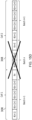
- Figure 14 illustrates re-transmitted repetitions being transmitted in the in-coverage period 802 of the second beam with the same characteristics which were used for the transmission in the in-coverage period 702 of the first beam according to example embodiments.
- a first MDPCCH 1302 is transmitted by the base station to the communications device 306 which schedules a PUSCH transmission 1306 spanning 4096 repetitions.
- the repetitions which span the leaving period 818 for the first beam and the entering period 916 for the second beam are dropped.
- the communications device re-transmits a part 1308 of the scheduled PUSCH transmission 1306 which was not transmitted during the in-coverage period 702 of the first beam using the same scrambling code and DMRS sequence as was used for a part 1304 of the scheduled PUSCH transmission 1306 which was transmitted during the in-coverage period 702 of the first beam.
- the communications device 306 switches from using the scrambling code and DMRS which was used for the part 1304 of the scheduled PUSCH transmission 1306 which was transmitted during the in-coverage period 702 of the first beam to using a scrambling code and DMRS sequence for the new cell corresponding to the coverage area 348 of the second beam.
- the communications device 306 may then receive and decode a second MPDCCH 1310 which schedules another PUSCH 1312 which the communications device 306 transmits using the scrambling code and DMRS sequence for the new cell corresponding to the coverage area 348 of the second beam.
- an RV and scrambling code are maintained for every 4 repetitions. For example if there are 16 repetitions, the 1st to 4th repetition may use one RV and scrambling code, the 5th to 8th repetitions may use another RV and another scrambling code.
- Such arrangements facilitate symbol combining at a receiver and cross subframe channel estimation for every batch of 4 repetitions. If the repetition is cut off during a batch (rather than at a batch boundary), a benefit of symbol combining and cross subframe channel estimation is reduced. Benefits of symbol combining can include improving a signal to noise (SNR) ratio and simplifying receiver design. Benefits of cross channel estimation can include improved robustness and/or channel estimation accuracy.
- SNR signal to noise
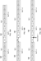
- FIG. 15A An example of a repetition being cut off during a batch is shown in Figure 15A.
- Figure 15A shows three batches of four repetitions, namely, Batch n-1, Batch n and Batch n+1. Each batch contains four repetitions which each share the same RV and scrambling code.
- the communications device 306 hands over from a first cell (which may correspond to coverage area 308 as explained above) to a second cell (which may correspond to coverage area 348 as explained above) between repetition 4n and repetition 4n+1.
- a repetition is cut off during the Batch n, thereby reducing the benefit of symbol combining and cross subframe channel estimation for the 4n and 4n+1 repetitions in Batch n.
- the Batch n may be referred to as a "cut-off batch".
- the "cut off" batch may be postponed.
- the repetition may be cut-off at a batch boundary rather than during a batch.
- the communications device 306 may delay transmission so that a new batch may be started in a new cell.
- Figure 15B illustrates the communications device 306 delaying a transmission to avoid a repetition being cut off during a batch.
- the batch n would be cut off after repetition 4n according to conventional systems.
- Figure 14B shows that the communications device 306 delays the transmission so that the repetition 4n starts after it has handed over to the second cell 348. The cut therefore occurs at a batch boundary between Batch n-1 and Batch n.
- the "cut off" batch may be restarted in a new cell.
- the communications device 306 may continue to transmit (or receive) a batch that is cut off but restarts the transmission (or reception) of the cut off batch in the new cell.
- Figure 15C illustrates an example of the communications device 306 restarting a cut-off batch in a new cell.
- batch n is due to be cut off after repetition 4n as a result of a handover of the communications device 306 from the first cell 308 to the second cell 348.
- the communications device 306 still transmits the 4n repetition in the first cell 308 but re-transmits the 4n repetition along with the remaining repetitions of the batch n when the communications device 306 enters the second cell 348.
- the cut off batch is dropped.
- An example of a cut off batch being dropped is shown in Figure 15D .
- batch n is due to be cut off after repetition 4n as a result of a handover of the communications device 306 from the first cell 308 to the second cell 348.
- the communications device drops the batch n in response to determining that the batch n is due to be a cut off batch. Such embodiments are particularly advantageous if an end time of a transmission needs to be maintained.
- the functionality of cutting off a batch may be implemented at either the communications device or the base station. For example, considering downlink transmissions, if a batch is cut-off by the base station, the base station refrains from transmitting repetitions from that batch. In this case, the communications device would not store LLRs in its buffers relating to repetitions falling within the cut-off batch. In contrast, if the batch is cut-off at the communications device, the communications device refrains from receiving repetitions from the cut-off batch. In this case, the base station scheduler may choose a number of repetitions accounting for the fact that the communications device would not receive some of the repetitions.
- SIB System Information Block
- MIB Master Information Block
- DCI or RRC signalling may indicate that communications device 306 stops PUSCH transmission and continues the PUSCH transmission during the in-coverage period 802 of the second beam.
- DCI or RRC signalling may indicate that communications device 306 stops PUSCH transmission when it changes cell (for example, at the end point 928 of the in-coverage period 702 of the first beam)
- infrastructure equipment and/or communications devices as herein defined may be further defined in accordance with the various arrangements and embodiments discussed in the preceding paragraphs. It would be further appreciated by those skilled in the art that such infrastructure equipment and communications devices as herein defined and described may form part of communications systems other than those defined by the present disclosure.
- Described embodiments may be implemented in any suitable form including hardware, software, firmware or any combination of these. Described embodiments may optionally be implemented at least partly as computer software running on one or more data processors and/or digital signal processors.
- the elements and components of any embodiment may be physically, functionally and logically implemented in any suitable way. Indeed the functionality may be implemented in a single unit, in a plurality of units or as part of other functional units. As such, the disclosed embodiments may be implemented in a single unit or may be physically and functionally distributed between different units, circuitry and/or processors.
Landscapes
- Engineering & Computer Science (AREA)
- Computer Networks & Wireless Communication (AREA)
- Signal Processing (AREA)
- Physics & Mathematics (AREA)
- Astronomy & Astrophysics (AREA)
- Aviation & Aerospace Engineering (AREA)
- General Physics & Mathematics (AREA)
- Mobile Radio Communication Systems (AREA)
Claims (15)
- Verfahren zum Betreiben einer Kommunikationsvorrichtung (306), um über ein drahtloses Kommunikationsnetzwerk, das eine nicht-terrestrische Infrastrukturausrüstung, NTN-Infrastrukturausrüstung, einschließt, zu übertragen oder zu empfangen, das Verfahren umfassend:Identifizieren, durch die Kommunikationsvorrichtung, eines ersten Abdeckungszeitraums, währenddessen die Kommunikationsvorrichtung Signale an eine erste NTN-Infrastrukturausrüstung übertragen oder von dieser empfangen kann, wobei die erste NTN-Infrastrukturausrüstung entweder durch ein erstes Luftfahrzeug (310) getragen wird oder die übertragenen oder empfangenen Signale über das erste Luftfahrzeug an die erste NTN-Infrastrukturausrüstung oder von dieser weitergeleitet werden, wenn das erste Luftfahrzeug die Kommunikationsvorrichtung überfliegt,Identifizieren, durch die Kommunikationsvorrichtung, eines zweiten Abdeckungszeitraums, währenddessen das Kommunikationsvorrichtung Signale an die erste NTN-Infrastrukturausrüstung oder eine zweite NTN-Infrastrukturausrüstung übertragen oder von dieser empfangen kann, wobei die zweite NTN-Infrastrukturausrüstung entweder durch ein zweites Luftfahrzeug (360) getragen wird oder die übertragenen oder empfangenen Signale über das zweite Luftfahrzeug an die zweite oder NTN-Infrastrukturausrüstung oder von dieser weitergeleitet werden, wenn das zweite Luftfahrzeug die Kommunikationsvorrichtung überfliegt, und entwederÜbertragen der Uplink-Daten an das drahtlose Kommunikationsnetzwerk durch Anpassen einer Übertragung der Uplink-Daten, um mindestens einen Teil des zweiten Abdeckungszeitraums einzuschließen, basierend auf einer Zeitdauer, die erforderlich ist, um die Uplink-Daten zu übertragen, und einer Startzeit, zu der die Uplink-Daten in dem ersten Abdeckungszeitraum in Bezug auf ein Ende des ersten Abdeckungszeitraums übertragen werden können, oderEmpfangen von Downlink-Daten von dem drahtlosen Kommunikationsnetzwerk durch Anpassen eines Empfangs der Downlink-Daten, um mindestens einen Teil des zweiten Abdeckungszeitraums einzuschließen, wobei diese mindestens teilweise in dem zweiten Abdeckungszeitraum übertragen wurden, basierend auf einer Zeitdauer, die erforderlich ist, um die Downlink-Daten zu empfangen, und einer Startzeit, zu der die Downlink-Daten in dem ersten Abdeckungszeitraum in Bezug auf ein Ende des ersten Abdeckungszeitraums empfangen werden können.
- Verfahren nach Anspruch 1, wobei das Anpassen der Übertragung der Uplink-Daten, um mindestens einen Teil des zweiten Abdeckungszeitraums einzuschließen, umfasstIdentifizieren, dass die Startzeit, zu der die Uplink-Daten übertragen werden können, während des ersten Abdeckungszeitraums liegt, und entwederÜbertragen der Uplink-Daten in einem Teil des ersten Abdeckungszeitraums und mindestens des Teils des zweiten Abdeckungszeitraums, oderVerzögern der Übertragung der Uplink-Daten, sodass sie mindestens in dem Teil des zweiten Abdeckungszeitraums beginnt.
- Verfahren nach Anspruch 2, wobei das Identifizieren der Startzeit, zu der die Uplink-Daten während des ersten Abdeckungszeitraums übertragen werden können, umfasst
Planen der Übertragung der Uplink-Daten während des ersten Abdeckungszeitraums. - Verfahren nach Anspruch 2, wobei das Planen der Übertragung der Uplink-Daten während der ersten Abdeckungsperiode umfasst
Empfangen von Downlink-Steuerinformationen von dem drahtlosen Kommunikationsnetzwerk, das die Übertragung der Uplink-Daten plant, wobei die Downlink-Steuerinformationen während des ersten Abdeckungszeitraums empfangen werden. - Verfahren nach Anspruch 4, wobei die Downlink-Steuerinformationen, die in dem ersten Abdeckungszeitraum empfangen werden, Zeit- und Frequenzressourcen des mindestens einen Teils des zweiten Abdeckungszeitraums identifizieren.
- Verfahren nach Anspruch 4, wobei das Planen der Übertragung der Uplink-Daten während des ersten Abdeckungszeitraums umfasstErkennen, durch die Transceiver-Schaltlogik der Kommunikationsvorrichtung, des Vorhandenseins der Uplink-Daten in einem Eingabepuffer für die Übertragung durch die Kommunikationsvorrichtung,Übertragen einer Anzeige eines Status des Puffers an das drahtlose Kommunikationsnetzwerk undals Reaktion darauf, Empfangen der Downlink-Steuerinformationen, die die Übertragung der Uplink-Daten planen.
- Verfahren nach Anspruch 3, wobei das Übertragen der Uplink-Daten umfasst
Übertragen der Uplink-Daten als eine Vielzahl von Wiederholungen einer redundanten Version eines Transportblocks, wobei die Anzahl der Vielzahl von Wiederholungen des Transportblocks die Zeitdauer, die zum Übertragen der Uplink-Daten erforderlich ist, bestimmt, wobei eine Anzahl der Vielzahl der redundanten Versionen in dem ersten Abdeckungszeitraum und eine zweite Anzahl der redundanten Versionen in dem zweiten Abdeckungszeitraum übertragen werden. - Verfahren nach Anspruch 1, wobei das Übertragen der Uplink-Daten umfasstÜbertragen der Uplink-Daten als eine Vielzahl von Wiederholungen einer redundanten Version eines Transportblocks, wobei die Anzahl der Vielzahl von Wiederholungen des Transportblocks die Zeitdauer, die zum Übertragen der Uplink-Daten erforderlich ist, bestimmt, und die Downlink-Steuerinformationen eine Anzahl der Vielzahl der redundanten Versionen anzeigen, die in der ersten Abdeckungsperiode zu übertragen sind, und das Verfahren umfasstBestimmen einer zweiten Anzahl der redundanten Versionen, die in dem zweiten Abdeckungszeitraum zu übertragen sind.
- Verfahren nach Anspruch 8, wobei das Bestimmen der zweiten Anzahl der redundanten Versionen, die in dem zweiten Abdeckungszeitraum zu übertragen sind, das Bestimmen einer verbleibenden Anzahl redundanter Versionen umfasst, nachdem die erste Anzahl von redundanten Versionen ab dem Startzeitpunkt übertragen wurde, zu dem die Uplink-Daten in dem ersten Abdeckungszeitraum übertragen werden können.
- Verfahren nach Anspruch 8, wobei das Bestimmen der zweiten Anzahl der redundanten Versionen, die in dem zweiten Abdeckungszeitraum zu übertragen sind, umfasst
Empfangen von zweiten Downlink-Steuerinformationen, die die zweite Anzahl von redundanten Versionen angeben. - Verfahren nach Anspruch 8, wobei das Übertragen der Uplink-Daten umfasst
Übertragen einer ersten Anzahl von Wiederholungen von redundanten Versionen der Uplink-Daten in dem ersten Abdeckungszeitraum ab dem Startzeitpunkt bis zu einem Umschaltzeitraum zwischen dem ersten Abdeckungszeitraum und dem zweiten Abdeckungszeitraum und einer zweiten Anzahl von Wiederholungen von redundanten Versionen der Uplink-Daten aus dem Umschaltzeitraum in dem zweiten Abdeckungszeitraum. - Verfahren nach Anspruch 1, wobei das Übertragen der Uplink-Daten umfasst
Übertragen der Uplink-Daten in mindestens einem Teil des zweiten Abdeckungszeitraums gemäß Medienzugriffssteuerungselementen, die von der drahtlosen Zugriffsschnittstelle zum Übertragen der Uplink-Daten in dem ersten Abdeckungszeitraum empfangen wurden. - Verfahren zum Betreiben einer nicht-terrestrischen Netzwerk-Infrastrukturausrüstung, NTN-Infrastrukturausrüstung, eines drahtlosen Kommunikationsnetzwerks zum Übertragen von Daten an oder Empfangen von Daten von einer oder mehreren Kommunikationsvorrichtungen, das Verfahren umfassend:Planen, durch die NTN-Infrastrukturausrüstung, einer Kommunikationsvorrichtung (306) während einer ersten Abdeckungsperiode, um Signale an die NTN-Infrastrukturausrüstung zu übertragen oder von dieser zu empfangen, wobei die NTN-Infrastrukturausrüstung entweder durch ein Luftfahrzeug getragen wird oder die übertragenen oder empfangenen Signale über das Luftfahrzeug an die NTN-Infrastrukturausrüstung oder von dieser weitergeleitet werden, wenn das Luftfahrzeug die Kommunikationsvorrichtung überfliegt, und entwederEmpfangen von Uplink-Daten durch Anpassen eines Empfangs der Uplink-Daten, um mindestens einen Teil eines zweiten Abdeckungszeitraums einzuschließen, basierend auf einer Zeitdauer, die erforderlich ist, um die Uplink-Daten zu übertragen, und einer Startzeit, zu der die Uplink-Daten in dem ersten Abdeckungszeitraum in Bezug auf ein Ende des ersten Abdeckungszeitraums übertragen werden können, wobei der zweite Abdeckungszeitraum ein Zeitraum ist, währenddessen die Kommunikationsvorrichtung Signale an die NTN-Infrastrukturausrüstung übertragen oder von dieser empfangen kann, oderÜbertragen von Downlink-Daten von dem drahtlosen Kommunikationsnetzwerk an die Kommunikationsvorrichtung, durch Anpassen einer Übertragung der Downlink-Daten, um mindestens einen Teil des zweiten Abdeckungszeitraums einzuschließen, wobei diese mindestens teilweise in dem zweiten Abdeckungszeitraum übertragen wurden, basierend auf einer Zeitdauer, die erforderlich ist, um die Downlink-Daten zu übertragen, und einer Startzeit, zu der die Downlink-Daten in dem ersten Abdeckungszeitraum in Bezug auf ein Ende des ersten Abdeckungszeitraums übertragen werden können.
- Kommunikationsvorrichtung (306) zum Übertragen oder Empfangen über ein drahtloses Kommunikationsnetzwerk, wobei das drahtlose Kommunikationsnetzwerk eine nicht-terrestrische Infrastrukturausrüstung, NTN-Infrastrukturausrüstung, umfasst, die Kommunikationsvorrichtung umfassendeine Transceiver-Schaltlogik, die konfiguriert ist, um Signale an die NTN-Infrastrukturausrüstung zu übertragen oder von dieser zu empfangen, undeine Steuerungsschaltlogik, die konfiguriert ist zumIdentifizieren eines ersten Abdeckungszeitraums, währenddessen die Kommunikationsvorrichtung Signale an eine erste NTN-Infrastrukturausrüstung übertragen oder von dieser empfangen kann, wobei die erste NTN-Infrastrukturausrüstung entweder durch ein erstes Luftfahrzeug (310) getragen wird oder die übertragenen oder empfangenen Signale über das erste Luftfahrzeug an die erste NTN-Infrastrukturausrüstung oder von dieser weitergeleitet werden, wenn das erste Luftfahrzeug die Kommunikationsvorrichtung überfliegt,Identifizieren eines zweiten Abdeckungszeitraums, währenddessen die Kommunikationsvorrichtung Signale an die erste NTN-Infrastrukturausrüstung oder eine zweite NTN-Infrastrukturausrüstung übertragen oder von dieser empfangen kann, wobei die zweite NTN-Infrastrukturausrüstung entweder durch ein zweites Luftfahrzeug (360) getragen wird oder die übertragenen oder empfangenen Signale über das zweite Luftfahrzeug an die zweite NTN-Infrastrukturausrüstung oder von dieser weitergeleitet werden, wenn das zweite Luftfahrzeug über die Kommunikationsvorrichtung überfliegt, und entwederSteuern der Transceiver-Schaltlogik, um Uplink-Daten an das drahtlose Kommunikationsnetzwerk zu übertragen, durch Anpassen einer Übertragung der Uplink-Daten, um mindestens einen Teil des zweiten Abdeckungszeitraums einzuschließen, basierend auf einer Zeitdauer, die erforderlich ist, um die Uplink-Daten zu übertragen, und einer Startzeit, zu der die Uplink-Daten in dem ersten Abdeckungszeitraum in Bezug auf ein Ende des ersten Abdeckungszeitraums übertragen werden können, oderSteuern der Transceiver-Schaltlogik, um Downlink-Daten von dem drahtlosen Kommunikationsnetzwerk zu empfangen, durch Anpassen eines Empfangs der Downlink-Daten, um mindestens einen Teil des zweiten Abdeckungszeitraums einzuschließen, wobei diese mindestens teilweise in dem zweiten Abdeckungszeitraum übertragen wurden, basierend auf einer Zeitdauer, die erforderlich ist, um die Downlink-Daten zu empfangen, und einer Startzeit, zu der die Downlink-Daten in dem ersten Abdeckungszeitraum in Bezug auf ein Ende des ersten Abdeckungszeitraums empfangen werden können.
- Nicht-terrestrische Netzwerk-Infrastrukturausrüstung, NTN-Infrastrukturausrüstung, zum Ausbilden eines Teils eines drahtlosen Kommunikationsnetzwerks zum Übertragen von Daten an oder Empfangen von Daten von einer oder mehreren Kommunikationsvorrichtungen, die NTN-Infrastrukturausrüstung umfassend:Transceiver-Schaltlogik, die konfiguriert ist, um Signale an die eine oder mehrere Kommunikationsvorrichtungen zu übertragen oder von diesen zu empfangen, undeine Steuerungsschaltlogik, die konfiguriert ist zumPlanen einer Kommunikationsvorrichtung (306) während eines ersten Abdeckungszeitraums, um Signale an die NTN-Infrastrukturausrüstung zu übertragen oder von dieser zu empfangen, wobei die NTN-Infrastrukturausrüstung entweder durch ein Luftfahrzeug getragen wird oder die übertragenen oder empfangenen Signale über das Luftfahrzeug an die NTN-Infrastrukturausrüstung oder von dieser weitergeleitet werden, wenn das Luftfahrzeug die Kommunikationsvorrichtung überfliegt, und entwederSteuern der Transceiver-Schaltung, um Uplink-Daten zu empfangen, durch Anpassen eines Empfangs der Uplink-Daten, um mindestens einen Teil eines zweiten Abdeckungszeitraums einzuschließen, basierend auf einer Zeitdauer, die erforderlich ist, um die Uplink-Daten zu übertragen, und einer Startzeit, zu der die Uplink-Daten in dem ersten Abdeckungszeitraum in Bezug auf ein Ende des ersten Abdeckungszeitraums übertragen werden können, wobei der zweite Abdeckungszeitraum ein Zeitraum ist, währenddessen die Kommunikationsvorrichtung Signale an die NTN-Infrastrukturausrüstung übertragen oder von dieser empfangen kann, oderSteuern der Transceiver-Schaltlogik, um Downlink-Daten von dem drahtlosen Kommunikationsnetzwerk an die Netzwerkvorrichtung zu übertragen, durch Anpassen einer Übertragung der Downlink-Daten, um mindestens einen Teil des zweiten Abdeckungszeitraums einzuschließen, wobei diese mindestens teilweise in dem zweiten Abdeckungszeitraum übertragen wurden, basierend auf einer Zeitdauer, die erforderlich ist, um die Downlink-Daten zu übertragen, und einer Startzeit, zu der die Downlink-Daten in dem ersten Abdeckungszeitraum in Bezug auf ein Ende des ersten Abdeckungszeitraums übertragen werden können.
Applications Claiming Priority (2)
| Application Number | Priority Date | Filing Date | Title |
|---|---|---|---|
| EP21166488 | 2021-03-31 | ||
| PCT/EP2022/058498 WO2022207758A1 (en) | 2021-03-31 | 2022-03-30 | Methods, communications device and infrastructure equipment for a non-terrestrial network |
Publications (2)
| Publication Number | Publication Date |
|---|---|
| EP4315656A1 EP4315656A1 (de) | 2024-02-07 |
| EP4315656B1 true EP4315656B1 (de) | 2025-04-23 |
Family
ID=75362364
Family Applications (1)
| Application Number | Title | Priority Date | Filing Date |
|---|---|---|---|
| EP22719583.1A Active EP4315656B1 (de) | 2021-03-31 | 2022-03-30 | Verfahren, kommunikationsvorrichtung und infrastrukturausrüstung für ein nicht terrestrisches netzwerk |
Country Status (3)
| Country | Link |
|---|---|
| US (1) | US20240172217A1 (de) |
| EP (1) | EP4315656B1 (de) |
| WO (1) | WO2022207758A1 (de) |
Family Cites Families (15)
| Publication number | Priority date | Publication date | Assignee | Title |
|---|---|---|---|---|
| EP3874789A1 (de) * | 2018-11-02 | 2021-09-08 | FRAUNHOFER-GESELLSCHAFT zur Förderung der angewandten Forschung e.V. | Terrestrische oder nicht-terrestrische drahtlose kommunikationssysteme |
| CN111565427B (zh) * | 2019-02-14 | 2022-05-13 | 华为技术有限公司 | 网络选择方法、网络设备以及终端设备 |
| WO2020231831A1 (en) * | 2019-05-10 | 2020-11-19 | Apple Inc. | Slot offset determination for non-terrestrial networks |
| WO2021058576A1 (en) * | 2019-09-25 | 2021-04-01 | Telefonaktiebolaget Lm Ericsson (Publ) | Methods for configuring polarization modes in a non-terrestrial network (ntn) |
| US11303353B2 (en) * | 2019-11-07 | 2022-04-12 | Qualcomm Incorporated | Systems and methods for supporting satellite access from mobile devices to public land mobile networks |
| EP3826384A1 (de) * | 2019-11-14 | 2021-05-26 | ASUSTek Computer Inc. | Verfahren und vorrichtung zur uplink-zeitsteuerungsbestimmung in einem drahtlosen kommunikationssystem |
| US11696189B2 (en) * | 2020-02-07 | 2023-07-04 | Qualcomm Incorporated | Handover mechanism for non-terrestrial network (NTN) system in 5G new radio (NR) |
| WO2021263076A1 (en) * | 2020-06-26 | 2021-12-30 | Comcast Cable Communications, Llc | Configuration for wireless communication in inactive or idle states |
| US20230292371A1 (en) * | 2020-08-06 | 2023-09-14 | Telefonaktiebolaget Lm Ericsson (Publ) | Rar window definition in ntn |
| EP4197263A4 (de) * | 2020-10-15 | 2025-02-05 | Sharp Kabushiki Kaisha | Mac-ce-befehlsaktionszeitsteuerung in nichtterrestrischen netzwerken |
| CN116420321A (zh) * | 2020-10-15 | 2023-07-11 | 联想(新加坡)私人有限公司 | 非地面网络中的随机接入过程 |
| EP4209044A4 (de) * | 2020-10-23 | 2024-06-12 | Apple Inc. | Modifizierte übergabeverfahren für mobile erdgebundene und erdgebundene strahlen |
| EP4016871A1 (de) * | 2020-12-15 | 2022-06-22 | Panasonic Intellectual Property Corporation of America | An übertragungsverfahren beteiligte ntn-entität, benutzergerät und basisstation |
| EP4278490A4 (de) * | 2021-01-14 | 2024-10-16 | Nokia Technologies Oy | Wiederholungsschema für übertragung |
| WO2022211499A1 (en) * | 2021-03-30 | 2022-10-06 | Samsung Electronics Co., Ltd. | Methods and user equipment (ue) for handling mbs service in wireless network |
-
2022
- 2022-03-30 WO PCT/EP2022/058498 patent/WO2022207758A1/en not_active Ceased
- 2022-03-30 US US18/283,818 patent/US20240172217A1/en active Pending
- 2022-03-30 EP EP22719583.1A patent/EP4315656B1/de active Active
Also Published As
| Publication number | Publication date |
|---|---|
| EP4315656A1 (de) | 2024-02-07 |
| US20240172217A1 (en) | 2024-05-23 |
| WO2022207758A1 (en) | 2022-10-06 |
Similar Documents
| Publication | Publication Date | Title |
|---|---|---|
| US12149957B2 (en) | Infrastructure equipment, communications devices and methods | |
| US20240373306A1 (en) | Infrastructure equipment, communications devices and methods | |
| US12550090B2 (en) | Methods, terminal, base station, circuitry and system for a non-terrestrial network | |
| US20240314664A1 (en) | Handover to a non terrestrial network (ntn) during small data transmission (sdt) | |
| US12587268B2 (en) | Methods, communications device and base station for a non-terrestrial network | |
| US20250211326A1 (en) | Methods, communications devices, and infrastructure equipment | |
| US20240129872A1 (en) | Methods, communications devices, and infrastructure equipment | |
| US20240171266A1 (en) | Methods, communications device and non-terrestrial network infrastructure equipment | |
| US20240396626A1 (en) | Methods, communications device and infrastructure equipment for a non-terrestrial network | |
| US20240421898A1 (en) | Methods, communications devices and infrastructure equipment | |
| US20250240741A1 (en) | Methods, communications devices, and infrastructure equipment | |
| EP4315656B1 (de) | Verfahren, kommunikationsvorrichtung und infrastrukturausrüstung für ein nicht terrestrisches netzwerk | |
| WO2022152631A1 (en) | Methods, communications device and infrastructure equipment for a non-terrestrial network | |
| CN120604623A (zh) | 通过无线接入网中继设备的设备到设备通信 | |
| US20240073857A1 (en) | Methods, communications device and infrastructure equipment for a non-terrestrial network |
Legal Events
| Date | Code | Title | Description |
|---|---|---|---|
| STAA | Information on the status of an ep patent application or granted ep patent |
Free format text: STATUS: UNKNOWN |
|
| STAA | Information on the status of an ep patent application or granted ep patent |
Free format text: STATUS: THE INTERNATIONAL PUBLICATION HAS BEEN MADE |
|
| PUAI | Public reference made under article 153(3) epc to a published international application that has entered the european phase |
Free format text: ORIGINAL CODE: 0009012 |
|
| STAA | Information on the status of an ep patent application or granted ep patent |
Free format text: STATUS: REQUEST FOR EXAMINATION WAS MADE |
|
| 17P | Request for examination filed |
Effective date: 20230925 |
|
| AK | Designated contracting states |
Kind code of ref document: A1 Designated state(s): AL AT BE BG CH CY CZ DE DK EE ES FI FR GB GR HR HU IE IS IT LI LT LU LV MC MK MT NL NO PL PT RO RS SE SI SK SM TR |
|
| DAV | Request for validation of the european patent (deleted) | ||
| DAX | Request for extension of the european patent (deleted) | ||
| GRAP | Despatch of communication of intention to grant a patent |
Free format text: ORIGINAL CODE: EPIDOSNIGR1 |
|
| STAA | Information on the status of an ep patent application or granted ep patent |
Free format text: STATUS: GRANT OF PATENT IS INTENDED |
|
| INTG | Intention to grant announced |
Effective date: 20241024 |
|
| P01 | Opt-out of the competence of the unified patent court (upc) registered |
Free format text: CASE NUMBER: APP_762/2025 Effective date: 20250108 |
|
| GRAS | Grant fee paid |
Free format text: ORIGINAL CODE: EPIDOSNIGR3 |
|
| GRAA | (expected) grant |
Free format text: ORIGINAL CODE: 0009210 |
|
| STAA | Information on the status of an ep patent application or granted ep patent |
Free format text: STATUS: THE PATENT HAS BEEN GRANTED |
|
| AK | Designated contracting states |
Kind code of ref document: B1 Designated state(s): AL AT BE BG CH CY CZ DE DK EE ES FI FR GB GR HR HU IE IS IT LI LT LU LV MC MK MT NL NO PL PT RO RS SE SI SK SM TR |
|
| REG | Reference to a national code |
Ref country code: GB Ref legal event code: FG4D |
|
| REG | Reference to a national code |
Ref country code: CH Ref legal event code: EP |
|
| REG | Reference to a national code |
Ref country code: DE Ref legal event code: R096 Ref document number: 602022013576 Country of ref document: DE |
|
| REG | Reference to a national code |
Ref country code: IE Ref legal event code: FG4D |
|
| REG | Reference to a national code |
Ref country code: NL Ref legal event code: FP |
|
| REG | Reference to a national code |
Ref country code: AT Ref legal event code: MK05 Ref document number: 1788822 Country of ref document: AT Kind code of ref document: T Effective date: 20250423 |
|
| PG25 | Lapsed in a contracting state [announced via postgrant information from national office to epo] |
Ref country code: FI Free format text: LAPSE BECAUSE OF FAILURE TO SUBMIT A TRANSLATION OF THE DESCRIPTION OR TO PAY THE FEE WITHIN THE PRESCRIBED TIME-LIMIT Effective date: 20250423 Ref country code: PT Free format text: LAPSE BECAUSE OF FAILURE TO SUBMIT A TRANSLATION OF THE DESCRIPTION OR TO PAY THE FEE WITHIN THE PRESCRIBED TIME-LIMIT Effective date: 20250825 Ref country code: ES Free format text: LAPSE BECAUSE OF FAILURE TO SUBMIT A TRANSLATION OF THE DESCRIPTION OR TO PAY THE FEE WITHIN THE PRESCRIBED TIME-LIMIT Effective date: 20250423 |
|
| REG | Reference to a national code |
Ref country code: LT Ref legal event code: MG9D |
|
| PG25 | Lapsed in a contracting state [announced via postgrant information from national office to epo] |
Ref country code: NO Free format text: LAPSE BECAUSE OF FAILURE TO SUBMIT A TRANSLATION OF THE DESCRIPTION OR TO PAY THE FEE WITHIN THE PRESCRIBED TIME-LIMIT Effective date: 20250723 Ref country code: GR Free format text: LAPSE BECAUSE OF FAILURE TO SUBMIT A TRANSLATION OF THE DESCRIPTION OR TO PAY THE FEE WITHIN THE PRESCRIBED TIME-LIMIT Effective date: 20250724 |
|
| PG25 | Lapsed in a contracting state [announced via postgrant information from national office to epo] |
Ref country code: PL Free format text: LAPSE BECAUSE OF FAILURE TO SUBMIT A TRANSLATION OF THE DESCRIPTION OR TO PAY THE FEE WITHIN THE PRESCRIBED TIME-LIMIT Effective date: 20250423 |
|
| PG25 | Lapsed in a contracting state [announced via postgrant information from national office to epo] |
Ref country code: BG Free format text: LAPSE BECAUSE OF FAILURE TO SUBMIT A TRANSLATION OF THE DESCRIPTION OR TO PAY THE FEE WITHIN THE PRESCRIBED TIME-LIMIT Effective date: 20250423 |
|
| PG25 | Lapsed in a contracting state [announced via postgrant information from national office to epo] |
Ref country code: HR Free format text: LAPSE BECAUSE OF FAILURE TO SUBMIT A TRANSLATION OF THE DESCRIPTION OR TO PAY THE FEE WITHIN THE PRESCRIBED TIME-LIMIT Effective date: 20250423 |
|
| PG25 | Lapsed in a contracting state [announced via postgrant information from national office to epo] |
Ref country code: AT Free format text: LAPSE BECAUSE OF FAILURE TO SUBMIT A TRANSLATION OF THE DESCRIPTION OR TO PAY THE FEE WITHIN THE PRESCRIBED TIME-LIMIT Effective date: 20250423 |
|
| PG25 | Lapsed in a contracting state [announced via postgrant information from national office to epo] |
Ref country code: RS Free format text: LAPSE BECAUSE OF FAILURE TO SUBMIT A TRANSLATION OF THE DESCRIPTION OR TO PAY THE FEE WITHIN THE PRESCRIBED TIME-LIMIT Effective date: 20250723 |
|
| PG25 | Lapsed in a contracting state [announced via postgrant information from national office to epo] |
Ref country code: IS Free format text: LAPSE BECAUSE OF FAILURE TO SUBMIT A TRANSLATION OF THE DESCRIPTION OR TO PAY THE FEE WITHIN THE PRESCRIBED TIME-LIMIT Effective date: 20250823 |
|
| PG25 | Lapsed in a contracting state [announced via postgrant information from national office to epo] |
Ref country code: LV Free format text: LAPSE BECAUSE OF FAILURE TO SUBMIT A TRANSLATION OF THE DESCRIPTION OR TO PAY THE FEE WITHIN THE PRESCRIBED TIME-LIMIT Effective date: 20250423 |
|
| PG25 | Lapsed in a contracting state [announced via postgrant information from national office to epo] |
Ref country code: SM Free format text: LAPSE BECAUSE OF FAILURE TO SUBMIT A TRANSLATION OF THE DESCRIPTION OR TO PAY THE FEE WITHIN THE PRESCRIBED TIME-LIMIT Effective date: 20250423 Ref country code: DK Free format text: LAPSE BECAUSE OF FAILURE TO SUBMIT A TRANSLATION OF THE DESCRIPTION OR TO PAY THE FEE WITHIN THE PRESCRIBED TIME-LIMIT Effective date: 20250423 |
|
| PG25 | Lapsed in a contracting state [announced via postgrant information from national office to epo] |
Ref country code: CZ Free format text: LAPSE BECAUSE OF FAILURE TO SUBMIT A TRANSLATION OF THE DESCRIPTION OR TO PAY THE FEE WITHIN THE PRESCRIBED TIME-LIMIT Effective date: 20250423 |
|
| PG25 | Lapsed in a contracting state [announced via postgrant information from national office to epo] |
Ref country code: EE Free format text: LAPSE BECAUSE OF FAILURE TO SUBMIT A TRANSLATION OF THE DESCRIPTION OR TO PAY THE FEE WITHIN THE PRESCRIBED TIME-LIMIT Effective date: 20250423 |
|
| REG | Reference to a national code |
Ref country code: DE Ref legal event code: R097 Ref document number: 602022013576 Country of ref document: DE |
|
| PG25 | Lapsed in a contracting state [announced via postgrant information from national office to epo] |
Ref country code: SK Free format text: LAPSE BECAUSE OF FAILURE TO SUBMIT A TRANSLATION OF THE DESCRIPTION OR TO PAY THE FEE WITHIN THE PRESCRIBED TIME-LIMIT Effective date: 20250423 |
|
| PG25 | Lapsed in a contracting state [announced via postgrant information from national office to epo] |
Ref country code: IT Free format text: LAPSE BECAUSE OF FAILURE TO SUBMIT A TRANSLATION OF THE DESCRIPTION OR TO PAY THE FEE WITHIN THE PRESCRIBED TIME-LIMIT Effective date: 20250423 |
|
| PLBE | No opposition filed within time limit |
Free format text: ORIGINAL CODE: 0009261 |
|
| STAA | Information on the status of an ep patent application or granted ep patent |
Free format text: STATUS: NO OPPOSITION FILED WITHIN TIME LIMIT |
|
| REG | Reference to a national code |
Ref country code: CH Ref legal event code: L10 Free format text: ST27 STATUS EVENT CODE: U-0-0-L10-L00 (AS PROVIDED BY THE NATIONAL OFFICE) Effective date: 20260304 |
|
| PGFP | Annual fee paid to national office [announced via postgrant information from national office to epo] |
Ref country code: NL Payment date: 20260219 Year of fee payment: 5 |