EP4314698B1 - Kugelsichere schutzstruktur - Google Patents
Kugelsichere schutzstruktur Download PDFInfo
- Publication number
- EP4314698B1 EP4314698B1 EP23717027.9A EP23717027A EP4314698B1 EP 4314698 B1 EP4314698 B1 EP 4314698B1 EP 23717027 A EP23717027 A EP 23717027A EP 4314698 B1 EP4314698 B1 EP 4314698B1
- Authority
- EP
- European Patent Office
- Prior art keywords
- elements
- structure according
- rigid
- bulletproof
- bulletproof structure
- Prior art date
- Legal status (The legal status is an assumption and is not a legal conclusion. Google has not performed a legal analysis and makes no representation as to the accuracy of the status listed.)
- Active
Links
Images



Classifications
-
- F—MECHANICAL ENGINEERING; LIGHTING; HEATING; WEAPONS; BLASTING
- F41—WEAPONS
- F41H—ARMOUR; ARMOURED TURRETS; ARMOURED OR ARMED VEHICLES; MEANS OF ATTACK OR DEFENCE, e.g. CAMOUFLAGE, IN GENERAL
- F41H5/00—Armour; Armour plates
- F41H5/02—Plate construction
- F41H5/04—Plate construction composed of more than one layer
- F41H5/0492—Layered armour containing hard elements, e.g. plates, spheres, rods, separated from each other, the elements being connected to a further flexible layer or being embedded in a plastics or an elastomer matrix
-
- F—MECHANICAL ENGINEERING; LIGHTING; HEATING; WEAPONS; BLASTING
- F41—WEAPONS
- F41H—ARMOUR; ARMOURED TURRETS; ARMOURED OR ARMED VEHICLES; MEANS OF ATTACK OR DEFENCE, e.g. CAMOUFLAGE, IN GENERAL
- F41H1/00—Personal protection gear
- F41H1/02—Armoured or projectile- or missile-resistant garments; Composite protection fabrics
-
- F—MECHANICAL ENGINEERING; LIGHTING; HEATING; WEAPONS; BLASTING
- F41—WEAPONS
- F41H—ARMOUR; ARMOURED TURRETS; ARMOURED OR ARMED VEHICLES; MEANS OF ATTACK OR DEFENCE, e.g. CAMOUFLAGE, IN GENERAL
- F41H5/00—Armour; Armour plates
- F41H5/02—Plate construction
- F41H5/04—Plate construction composed of more than one layer
- F41H5/0414—Layered armour containing ceramic material
- F41H5/0428—Ceramic layers in combination with additional layers made of fibres, fabrics or plastics
-
- F—MECHANICAL ENGINEERING; LIGHTING; HEATING; WEAPONS; BLASTING
- F41—WEAPONS
- F41H—ARMOUR; ARMOURED TURRETS; ARMOURED OR ARMED VEHICLES; MEANS OF ATTACK OR DEFENCE, e.g. CAMOUFLAGE, IN GENERAL
- F41H5/00—Armour; Armour plates
- F41H5/02—Plate construction
- F41H5/04—Plate construction composed of more than one layer
- F41H5/0414—Layered armour containing ceramic material
- F41H5/0428—Ceramic layers in combination with additional layers made of fibres, fabrics or plastics
- F41H5/0435—Ceramic layers in combination with additional layers made of fibres, fabrics or plastics the additional layers being only fibre- or fabric-reinforced layers
-
- F—MECHANICAL ENGINEERING; LIGHTING; HEATING; WEAPONS; BLASTING
- F41—WEAPONS
- F41H—ARMOUR; ARMOURED TURRETS; ARMOURED OR ARMED VEHICLES; MEANS OF ATTACK OR DEFENCE, e.g. CAMOUFLAGE, IN GENERAL
- F41H5/00—Armour; Armour plates
- F41H5/02—Plate construction
- F41H5/04—Plate construction composed of more than one layer
- F41H5/0442—Layered armour containing metal
- F41H5/0457—Metal layers in combination with additional layers made of fibres, fabrics or plastics
-
- F—MECHANICAL ENGINEERING; LIGHTING; HEATING; WEAPONS; BLASTING
- F41—WEAPONS
- F41H—ARMOUR; ARMOURED TURRETS; ARMOURED OR ARMED VEHICLES; MEANS OF ATTACK OR DEFENCE, e.g. CAMOUFLAGE, IN GENERAL
- F41H5/00—Armour; Armour plates
- F41H5/02—Plate construction
- F41H5/04—Plate construction composed of more than one layer
- F41H5/0442—Layered armour containing metal
- F41H5/0457—Metal layers in combination with additional layers made of fibres, fabrics or plastics
- F41H5/0464—Metal layers in combination with additional layers made of fibres, fabrics or plastics the additional layers being only fibre- or fabric-reinforced layers
Definitions
- the present invention refers to a bulletproof protective structure, composed of a flexible base constituted by a ballistic fabric and of a panel made of rigid elements of ballistic material adhering to a second layer of ballistic fabric.
- the invention concerns a protective structure suitable for making bulletproof vests or panels capable of guaranteeing high levels of protection, in particular higher than level IIIa according to US NIJ regulations.
- Effective bulletproof protections are known to be obtained by means of structures made by combining intertwined or unidirectional fibers capable of absorbing and dispersing the force of impact and penetration of the bullets through plastic deformation (elongation) of the fibers themselves;
- the fibres most commonly used for this purpose are the aramid fibres generally known by the name “Kevlar ® " (registered trademark of E. I. du Pont de Nemours and Company), or the ultra-high molecular weight polyethylene fibers (also known as UHMWPE), in particular the Dyneema ® fibers (registered trademark of Royal DSM N.V.).
- the number of overlapping layers determines the protection capacity of the structure.
- fiber-only structures can provide effective protection against firearm bullets up to gauge 7.65 9 Parabellum 357 and 44 Magnum. This corresponds to a protection level IIIa according to the regulations defined by the US National Institute of Justice (NIJ).
- NIJ National Institute of Justice
- These structures are particularly light, usually have an areal density that can vary between 4.5 and 7 kg/m 2 , are comfortable to wear and with a degree of flexibility that allows large zones of the body to be covered.
- these structures made of polymer fiber alone are not sufficient for protecting against bullets with gauge greater than those indicated above, for example those fired by long weapons such as 7.62 x 51 NATO BALL, 7.62 x 39, AK47 and SS109 NATO.
- rigid elements capable of fragmenting the bullets fired by long weapons into smaller parts that can be more easily stopped by the underlying fiber structure, also thanks to the decrease in their energy.
- These rigid elements can be adjacent or spaced from each other, and are made of metallic materials or more often with the so-called ballistic ceramics, in particular alumina (aluminum oxide), silicon carbide or boron carbide, able to fragment the bullets and divide them into chips.
- one possibility is to adopt flexible configurations, which comprise a non-monolithic ceramic layer, but based on mosaics of small-sized tiles (about 30 mm x 30 mm), associated with a support that is also flexible.
- patent EP 3098560 B1 A structure of this type is disclosed in patent EP 3098560 B1 .
- the rigid elements are in the form of short prisms (square-based parallelepipeds or hexagonal prisms are exemplified), adjacent to each other along their lateral surfaces and glued to a ballistic fabric via one of their basal surfaces.
- This structure has the disadvantage of still presenting a limited flexibility, due to the fact that the elements are glued on the entire surface of contact with the fabric, so that the bending zone is limited only to lines at their edges.
- patent application EP 3805691 A1 describes a structure consisting of rigid elements glued on a base in ballistic fibers, wherein the rigid elements have a complex shape, with a central raised zone on the basal face destined for gluing with the fibers.
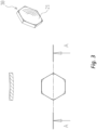
- Two embodiments of rigid elements of this document are shown schematically in Figures 5 and 6 ; in the two figures, an equal number corresponds to an equal element. In Fig.
- a first possible rigid element is shown, respectively in a top view in the upper part of the figure and in a side view in the lower part of the figure;
- this rigid element, A has a hexagonal plan section, and consists of a main part, 1, with a flat front face 3 and on whose rear face there is a raised part 2, which does not occupy the entire area of said rear face (a part 2 with circular plan section is exemplified, identified by the dashed line in the upper part of the figure), and which has a face 4 destined for gluing with the fibers.
- FIG. 6 shows a second possible embodiment of the rigid element of the aforementioned application; the rigid element B is analogous to element A, except for the part 5 which differs from the part 1 due to the presence of a recess 6 on the front face 3, identified by a dashed line in the lower part of the figure; this second embodiment is preferable because it lightens the structure.
- the structures of this document are more flexible than the previous one, because the gluing zones are not adjacent and there is a space between them that allows an easier bending of the structure.
- the ballistic ceramic elements are typically produced by techniques of cold pressing of mixtures of ceramic powders and organic binders and subsequent heat treatment that removes the binder and sinters the powders, but with these techniques it is problematic obtaining parts with sharp angles, for example the angle between the rear face of the parts 1 or 5 and the part 2 of the elements described above, and the lines corresponding to these sharp angles are zones of possible fragility for the resulting ceramic body.
- rigid elements with such sharply angled section profiles have limited mechanical resistance, which forces to further increase their thickness and therefore their weight.
- Patent application EP 1980813 A2 discloses a bulletproof structure comprising a flexible base consisting of ballistic fibers on which rigid metallic or ceramic elements are adhered adjacent to each other, wherein the face of said elements adhering to the fibers is convex and the rigid elements adhere to the flexible base only for a fraction of said convex surface.
- Another problem encountered with the known structures made of rigid ballistic ceramic elements is a decay in the performance on the edge: a bullet impacting the edge of the element, thus also hitting the adjacent element, is more likely to penetrate the structure; currently, to overcome the problem, the thickness of the ceramic elements is sized so as to ensure sufficient mechanical performance at the edges; this results in the thickness used at the center of the element being oversized compared to what is necessary, with a consequent increase in the weight of the final structure.
- Aim of the present invention is to realize a bulletproof structure with a degree of flexibility sufficient to ensure full-body coverage with a protection level higher than level IIIa of the US NIJ standard, but without the problems of the prior art.
- aim of the invention is to provide a bulletproof protective structure with improved performance at the edges of the rigid elements without having to increase their thickness uniformly and therefore the overall weight of the final structure.
- a bulletproof structure comprising a flexible base consisting of intertwined or unidirectional ballistic fibers on which rigid metallic or ceramic elements are adhered adjacent to each other, wherein the face of said elements adhering to the fibers is convex, the opposite face of said elements is concave and the thickness at the edge of the element is between 0.5 and 2 mm greater than the thickness at the center of the element itself, the rigid elements adhere to the flexible base only for a fraction of said convex surface, and in a plan view they have a polygonal or pseudo-polygonal shape, such that there are no voids between the sides of two abutting elements.
- Figures 5 and 6 relate to ceramic elements of the prior art, and have already been described above.
- the dimensions are not necessarily to scale, and some dimensions can be increased to highlight constructional details of the elements and of the structures of the invention; in these Figures, moreover, an equal number corresponds to an equal element.
- the bulletproof structure of the invention comprises a flexible base, made of ballistic fibers on which rigid elements are adhered which have the surface adhering to the flexible base which has a convex shape and therefore is neither flat nor comprises flat portions.
- These rigid elements have two main surfaces, with greater extension, destined the former to stop the bullets and the latter to adhere to the flexible base of polymer fibers, and lateral surfaces with smaller extension that in the overall structure are adjacent to each other.
- the concave surface destined to stop the bullets will also be defined as the front surface, while the convex one, destined to adhere to the flexible base of polymer fibers, in the following will also be defined as the rear surface.
- Fig. 1 shows a schematic sectional view of a generic rigid element for the realization of a bulletproof structure of the prior art: the element, 10, comprises a front surface, 11, which has any geometry and is typically flat, and a convex rear surface, 12; the lateral surfaces are indicated in the figure as surfaces 13; the radius of curvature of the convex surface, 12, is between 40 and 350 mm, preferably between 80 and 250 mm and even more preferably between 100 and 180 mm.
- Fig. 2 shows a schematic sectional view of a rigid element, 20, for the realization of a bulletproof structure of the invention.
- Both main faces of said rigid element are curved surfaces, the front face 21 is concave and the rear face 12 convex, said rigid elements adhere to the flexible base for a fraction of their convex surface, and the thickness at the edge of the element is between 0.5 and 2 mm greater than the thickness at the center of the element itself.
- This geometry allows to lighten the rigid elements given their smaller thickness at the center with respect to the rigid element 10, and consequently to decrease the weight of the bulletproof structure as a whole; at the same time, the greater thickness at the edges with respect to the center of the elements of type 20 guarantees the necessary mechanical resistance to the impact of the bullets in this zone, which is a critical characteristic of the known bulletproof structures.
- the two main faces, 12 and 21, of a rigid element of type 20 are two portions of spherical caps; in this case, the condition that the thickness at the edge of the element is between 0.5 and 2 mm greater than the thickness at the center of the element itself entails that the radius of curvature of the concave surface 21 is less than that of the convex surface 12.
- the radius of curvature of the concave surface can vary between 30 and 300 mm; the radius of curvature of the convex surface will vary accordingly, to ensure the condition of greater thickness at the edge with respect to the center of the element.
- the rigid elements of type 20 are produced with the materials that are typically used for this application, i.e. metals or, preferably, ballistic ceramics such as aluminium oxide (alumina), silicon carbide or boron carbide.
- the production methods for these rigid elements are well known to those skilled in the art, and generally consist in sintering powders of the aforementioned materials, typically at temperatures between 1500 and 2200 °C.
- the advantage of the rigid elements of the invention with respect to those known is that since the two main surfaces are spherical, during their production the pressure is exerted uniformly in all their points, which ensures the maximum homogeneity of structural and mechanical characteristics of the rigid elements obtained.
- the rigid elements of the structures of the invention may have any shape suitable for tessellating a flat surface, i.e. typically triangular, rectangular, preferably square or even more preferably hexagonal shape.
- Fig. 3 shows, in plan, sectional and perspective views, a rigid element 30 with the preferred hexagonal geometry in plan, and with concave front face 21.
- the lateral dimensions of the rigid elements useful for the invention may vary within wide margins; for the preferred hexagonal shape, the lateral dimensions may vary indicatively between 10 and 50 mm, while the thicknesses typically vary between 2 and 10 mm.
- the flexible base is the same as the one of known bulletproof structures.
- This base is made with the aramid (for example Kevlar ® ) or ultra-high molecular weight polyethylene (UHMWPE, for example Dyneema ® ) fibers mentioned above; the fibers can be arranged unidirectionally, variously intertwined or woven, according to methods known to those skilled in the art.
- the number of layers of fibers can be varied, depending on the degree of protection to be obtained; typically the flexible base has a thickness between about 1 to 5 mm.
- the rigid elements are adhered to the base in polymer fibers by gluing, typically with thermoplastic elastomeric resins, for example polyurethane elastomers.
- FIG. 4 in the upper part of the figure there is shown a sectional view of a structure 40 made of a series of rigid elements of the invention, 41, 41', 41", ..., adhering to the flexible base 42 in the zones 43, 43', 43",...; in the lower part of the figure there is instead shown a plan view of the structure 40, in which the rigid elements 41, 41', 41", ... have the preferred hexagonal shape, and the dashed circular central zones represent the areas for gluing 43, 43', 43", ... to the base 42.
- the gluing zones are relatively far apart, and the base 42 is free to bend and curve between two contiguous gluing zones, while in the gluing-free zones the rigid elements 41, 41', 41", ..., which are not constrained to each other, will be able to rise with respect to the base 42 while the latter is being bent.
- the bulletproof structure is then completed with an additional layer of textile material, not necessarily of ballistic type, arranged on the front part of the rigid elements, for aesthetic reasons and to favour the maintenance of the correct positioning of said elements.
Landscapes
- Engineering & Computer Science (AREA)
- General Engineering & Computer Science (AREA)
- Aiming, Guidance, Guns With A Light Source, Armor, Camouflage, And Targets (AREA)
Claims (10)
- Kugelsichere Struktur (40), umfassend eine flexible Basis (42), die aus verschlungenen oder unidirektionalen ballistischen Fasern besteht, auf denen starre metallische oder keramische Elemente (20; 30; 41, 41', 41", ...) benachbart zueinander haften, wobei- die Oberfläche (12) der Elemente, die an den Fasern haften, konvex ist und die Oberfläche (21) der starren Elemente (20; 30; 41, 41', 41", ...) gegenüber der konvexen Oberfläche konkav ist;- die Dicke an der Kante (13) des Elements zwischen 0,5 und 2 mm größer als die Dicke in der Mitte desselben Elements ist;- die starren Elemente für einen Bruchteil der konvexen Oberfläche an der flexiblen Basis haften; und- sie in einer Draufsicht eine polygonale oder pseudopolygonale Form aufweisen, so dass es keine Hohlräume zwischen den Seiten von zwei aneinanderstoßenden Elementen gibt.
- Kugelsichere Struktur nach Anspruch 1, dadurch gekennzeichnet, dass die zwei konvexen und konkaven Flächen (12, 21) zwei Abschnitte von kugelförmigen Kappen sind und der Krümmungsradius der konkaven Oberfläche (21) kleiner als der Krümmungsradius der konvexen Oberfläche ist.
- Kugelsichere Struktur nach Anspruch 2, wobei der Krümmungsradius der konkaven Oberfläche (21) zwischen 30 und 300 mm beträgt.
- Kugelsichere Struktur nach einem der Ansprüche 2 und 3, wobei der Krümmungsradius der konvexen Oberfläche (12) zwischen 40 und 350 mm beträgt.
- Kugelsichere Struktur nach Anspruch 4, wobei der Krümmungsradius der konvexen Oberfläche (12) zwischen 80 und 250 mm beträgt.
- Kugelsichere Struktur nach Anspruch 5, wobei der Krümmungsradius der konvexen Oberfläche (12) zwischen 100 und 180 mm beträgt.
- Kugelsichere Struktur nach einem der vorhergehenden Ansprüche, wobei die starren Elemente in einer Draufsicht eine dreieckige, rechteckige, quadratische oder hexagonale Form aufweisen.
- Kugelsichere Struktur nach einem der vorhergehenden Ansprüche, wobei die starren Elemente seitliche Abmessungen zwischen 10 und 50 mm und eine Dicke zwischen 2 und 10 mm aufweisen.
- Kugelsichere Struktur nach einem der vorhergehenden Ansprüche, wobei die flexible Basis (42) aus Aramid- oder ultrahochmolekularen Polyethylen(UHMWPE)-Fasern hergestellt ist und eine Dicke zwischen 1 und 5 mm aufweist.
- Kugelsichere Struktur nach einem der vorhergehenden Ansprüche, wobei die starren Elemente aus Aluminiumoxid, Siliciumcarbid oder Borcarbid hergestellt sind.
Applications Claiming Priority (2)
| Application Number | Priority Date | Filing Date | Title |
|---|---|---|---|
| IT102022000007115A IT202200007115A1 (it) | 2022-04-11 | 2022-04-11 | Struttura di protezione antiproiettile |
| PCT/EP2023/057465 WO2023198422A1 (en) | 2022-04-11 | 2023-03-23 | Bulletproof protective structure |
Publications (3)
| Publication Number | Publication Date |
|---|---|
| EP4314698A1 EP4314698A1 (de) | 2024-02-07 |
| EP4314698B1 true EP4314698B1 (de) | 2024-05-15 |
| EP4314698C0 EP4314698C0 (de) | 2024-05-15 |
Family
ID=82196503
Family Applications (1)
| Application Number | Title | Priority Date | Filing Date |
|---|---|---|---|
| EP23717027.9A Active EP4314698B1 (de) | 2022-04-11 | 2023-03-23 | Kugelsichere schutzstruktur |
Country Status (5)
| Country | Link |
|---|---|
| US (1) | US12050089B2 (de) |
| EP (1) | EP4314698B1 (de) |
| IT (1) | IT202200007115A1 (de) |
| PL (1) | PL4314698T3 (de) |
| WO (1) | WO2023198422A1 (de) |
Family Cites Families (17)
| Publication number | Priority date | Publication date | Assignee | Title |
|---|---|---|---|---|
| US5996115A (en) * | 1992-08-24 | 1999-12-07 | Ara, Inc. | Flexible body armor |
| GB9309486D0 (en) * | 1993-05-05 | 1993-06-23 | Patchett Kim | Flexible sheet material |
| US6170378B1 (en) * | 1998-11-09 | 2001-01-09 | Murray L. Neal | Method and apparatus for defeating high-velocity projectiles |
| IL138897A0 (en) * | 2000-10-05 | 2004-08-31 | Cohen Michael | Composite armor panel |
| US6826996B2 (en) * | 2002-03-11 | 2004-12-07 | General Dynamics Land Systems, Inc. | Structural composite armor and method of manufacturing it |
| US7383762B2 (en) * | 2005-04-03 | 2008-06-10 | Michael Cohen | Ceramic pellets and composite armor panel containing the same |
| US20100005955A1 (en) * | 2005-04-12 | 2010-01-14 | Mjd Innovations, L.L.C. | Body armor structure, method and performance |
| IL182511A (en) * | 2007-04-12 | 2014-07-31 | Yoav Hirschberg | Semi-finished protective layer, method of manufacture and a protective panel produced from it |
| US20080307553A1 (en) * | 2007-06-12 | 2008-12-18 | Energy Science Llc | Method And Apparatus For Protecting Against Ballistic Projectiles |
| US8434396B1 (en) * | 2007-07-23 | 2013-05-07 | Verco Materials, Llc | Armor arrangement |
| US9187909B2 (en) * | 2007-08-05 | 2015-11-17 | Robert G. Lee | Tile system |
| BRPI1005268A2 (pt) * | 2010-12-23 | 2013-04-16 | Inst Militar De Engenharia Ime | material cerÂmico sinterizado, processo para sua produÇço, e seu uso em blindagem balÍstica |
| ITUB20151170A1 (it) | 2015-05-28 | 2016-11-28 | Elet Ca S R L Con Socio Unico | Struttura di protezione antiproiettile e corrispondente giubbotto antiproiettile |
| US11473877B2 (en) * | 2018-05-24 | 2022-10-18 | Verco Materials, Llc | Ballistic tile |
| EP3805691B1 (de) | 2019-10-07 | 2023-09-06 | ELET.CA S.r.l. con Socio Unico | Schusssichere elementare schutzkomponente und entsprechende ballistische platte und schusssichere schutzstruktur, insbesondere in form einer schusssicheren weste |
| US11884047B1 (en) * | 2020-01-26 | 2024-01-30 | Jeremy Adelson | Impact absorbing composite material and methods of fabricating the same |
| WO2023137429A1 (en) * | 2022-01-14 | 2023-07-20 | Verco Materials, Llc | Ceramic tile design improvement for conformal personal armor |
-
2022
- 2022-04-11 IT IT102022000007115A patent/IT202200007115A1/it unknown
-
2023
- 2023-02-07 US US18/165,497 patent/US12050089B2/en active Active
- 2023-03-23 EP EP23717027.9A patent/EP4314698B1/de active Active
- 2023-03-23 WO PCT/EP2023/057465 patent/WO2023198422A1/en not_active Ceased
- 2023-03-23 PL PL23717027.9T patent/PL4314698T3/pl unknown
Also Published As
| Publication number | Publication date |
|---|---|
| PL4314698T3 (pl) | 2024-08-19 |
| US12050089B2 (en) | 2024-07-30 |
| US20230384061A1 (en) | 2023-11-30 |
| EP4314698C0 (de) | 2024-05-15 |
| WO2023198422A1 (en) | 2023-10-19 |
| EP4314698A1 (de) | 2024-02-07 |
| IT202200007115A1 (it) | 2023-10-11 |
Similar Documents
| Publication | Publication Date | Title |
|---|---|---|
| US7540228B1 (en) | Ceramic armour and method of construction | |
| US20120174754A1 (en) | Ceramic armour and method of construction | |
| EP2742311B1 (de) | Verbesserte mehrlagige struktur für ballistischen schutz | |
| US8434396B1 (en) | Armor arrangement | |
| EP2702348B1 (de) | Panzerungssystem | |
| AU2004245982B2 (en) | Corrugated ballistic armor | |
| US9322621B2 (en) | Armor system | |
| US11473877B2 (en) | Ballistic tile | |
| EP3098560A1 (de) | Kugelsichere schutzstruktur und zugehörige kugelsichere weste | |
| RU2641542C2 (ru) | Баллистическая защита с многослойной структурой, включающая в себя множество жестких элементов | |
| GB2130073A (en) | Protective shield | |
| US20120186434A1 (en) | Ballistic Lightweight ceramic armor with resistant devices based on geometric shapes | |
| KR20100004357A (ko) | 비늘형 세라믹 타일을 적용한 하이브리드 개인용 방탄복 | |
| US12050089B2 (en) | Bulletproof protective structure | |
| US8438963B2 (en) | High density ceramic bodies and composite armor comprising the same | |
| CN212372860U (zh) | 合金复合型缓冲层及防弹插板 | |
| RU2462682C2 (ru) | Высокоплотные керамические блоки и включающая их композитная броня | |
| US11378359B2 (en) | Armor systems with pressure wave redirection technology | |
| EP2898286B1 (de) | Panzerungssystem | |
| JP7859255B2 (ja) | 耐弾プレート用部材および耐弾プレート |
Legal Events
| Date | Code | Title | Description |
|---|---|---|---|
| STAA | Information on the status of an ep patent application or granted ep patent |
Free format text: STATUS: UNKNOWN |
|
| STAA | Information on the status of an ep patent application or granted ep patent |
Free format text: STATUS: THE INTERNATIONAL PUBLICATION HAS BEEN MADE |
|
| PUAI | Public reference made under article 153(3) epc to a published international application that has entered the european phase |
Free format text: ORIGINAL CODE: 0009012 |
|
| STAA | Information on the status of an ep patent application or granted ep patent |
Free format text: STATUS: REQUEST FOR EXAMINATION WAS MADE |
|
| GRAP | Despatch of communication of intention to grant a patent |
Free format text: ORIGINAL CODE: EPIDOSNIGR1 |
|
| STAA | Information on the status of an ep patent application or granted ep patent |
Free format text: STATUS: GRANT OF PATENT IS INTENDED |
|
| 17P | Request for examination filed |
Effective date: 20231025 |
|
| AK | Designated contracting states |
Kind code of ref document: A1 Designated state(s): AL AT BE BG CH CY CZ DE DK EE ES FI FR GB GR HR HU IE IS IT LI LT LU LV MC ME MK MT NL NO PL PT RO RS SE SI SK SM TR |
|
| DAV | Request for validation of the european patent (deleted) | ||
| DAX | Request for extension of the european patent (deleted) | ||
| INTG | Intention to grant announced |
Effective date: 20240131 |
|
| GRAS | Grant fee paid |
Free format text: ORIGINAL CODE: EPIDOSNIGR3 |
|
| GRAA | (expected) grant |
Free format text: ORIGINAL CODE: 0009210 |
|
| STAA | Information on the status of an ep patent application or granted ep patent |
Free format text: STATUS: THE PATENT HAS BEEN GRANTED |
|
| AK | Designated contracting states |
Kind code of ref document: B1 Designated state(s): AL AT BE BG CH CY CZ DE DK EE ES FI FR GB GR HR HU IE IS IT LI LT LU LV MC ME MK MT NL NO PL PT RO RS SE SI SK SM TR |
|
| REG | Reference to a national code |
Ref country code: CH Ref legal event code: EP |
|
| REG | Reference to a national code |
Ref country code: DE Ref legal event code: R096 Ref document number: 602023000098 Country of ref document: DE |
|
| REG | Reference to a national code |
Ref country code: IE Ref legal event code: FG4D |
|
| U01 | Request for unitary effect filed |
Effective date: 20240607 |
|
| U07 | Unitary effect registered |
Designated state(s): AT BE BG DE DK EE FI FR IT LT LU LV MT NL PT SE SI Effective date: 20240620 |
|
| PG25 | Lapsed in a contracting state [announced via postgrant information from national office to epo] |
Ref country code: IS Free format text: LAPSE BECAUSE OF FAILURE TO SUBMIT A TRANSLATION OF THE DESCRIPTION OR TO PAY THE FEE WITHIN THE PRESCRIBED TIME-LIMIT Effective date: 20240915 |
|
| PG25 | Lapsed in a contracting state [announced via postgrant information from national office to epo] |
Ref country code: HR Free format text: LAPSE BECAUSE OF FAILURE TO SUBMIT A TRANSLATION OF THE DESCRIPTION OR TO PAY THE FEE WITHIN THE PRESCRIBED TIME-LIMIT Effective date: 20240515 |
|
| PG25 | Lapsed in a contracting state [announced via postgrant information from national office to epo] |
Ref country code: GR Free format text: LAPSE BECAUSE OF FAILURE TO SUBMIT A TRANSLATION OF THE DESCRIPTION OR TO PAY THE FEE WITHIN THE PRESCRIBED TIME-LIMIT Effective date: 20240816 |
|
| PG25 | Lapsed in a contracting state [announced via postgrant information from national office to epo] |
Ref country code: ES Free format text: LAPSE BECAUSE OF FAILURE TO SUBMIT A TRANSLATION OF THE DESCRIPTION OR TO PAY THE FEE WITHIN THE PRESCRIBED TIME-LIMIT Effective date: 20240515 |
|
| PG25 | Lapsed in a contracting state [announced via postgrant information from national office to epo] |
Ref country code: NO Free format text: LAPSE BECAUSE OF FAILURE TO SUBMIT A TRANSLATION OF THE DESCRIPTION OR TO PAY THE FEE WITHIN THE PRESCRIBED TIME-LIMIT Effective date: 20240815 Ref country code: IS Free format text: LAPSE BECAUSE OF FAILURE TO SUBMIT A TRANSLATION OF THE DESCRIPTION OR TO PAY THE FEE WITHIN THE PRESCRIBED TIME-LIMIT Effective date: 20240915 Ref country code: HR Free format text: LAPSE BECAUSE OF FAILURE TO SUBMIT A TRANSLATION OF THE DESCRIPTION OR TO PAY THE FEE WITHIN THE PRESCRIBED TIME-LIMIT Effective date: 20240515 Ref country code: GR Free format text: LAPSE BECAUSE OF FAILURE TO SUBMIT A TRANSLATION OF THE DESCRIPTION OR TO PAY THE FEE WITHIN THE PRESCRIBED TIME-LIMIT Effective date: 20240816 Ref country code: ES Free format text: LAPSE BECAUSE OF FAILURE TO SUBMIT A TRANSLATION OF THE DESCRIPTION OR TO PAY THE FEE WITHIN THE PRESCRIBED TIME-LIMIT Effective date: 20240515 Ref country code: RS Free format text: LAPSE BECAUSE OF FAILURE TO SUBMIT A TRANSLATION OF THE DESCRIPTION OR TO PAY THE FEE WITHIN THE PRESCRIBED TIME-LIMIT Effective date: 20240815 |
|
| PG25 | Lapsed in a contracting state [announced via postgrant information from national office to epo] |
Ref country code: CZ Free format text: LAPSE BECAUSE OF FAILURE TO SUBMIT A TRANSLATION OF THE DESCRIPTION OR TO PAY THE FEE WITHIN THE PRESCRIBED TIME-LIMIT Effective date: 20240515 |
|
| PG25 | Lapsed in a contracting state [announced via postgrant information from national office to epo] |
Ref country code: RO Free format text: LAPSE BECAUSE OF FAILURE TO SUBMIT A TRANSLATION OF THE DESCRIPTION OR TO PAY THE FEE WITHIN THE PRESCRIBED TIME-LIMIT Effective date: 20240515 Ref country code: SK Free format text: LAPSE BECAUSE OF FAILURE TO SUBMIT A TRANSLATION OF THE DESCRIPTION OR TO PAY THE FEE WITHIN THE PRESCRIBED TIME-LIMIT Effective date: 20240515 |
|
| PG25 | Lapsed in a contracting state [announced via postgrant information from national office to epo] |
Ref country code: SM Free format text: LAPSE BECAUSE OF FAILURE TO SUBMIT A TRANSLATION OF THE DESCRIPTION OR TO PAY THE FEE WITHIN THE PRESCRIBED TIME-LIMIT Effective date: 20240515 |
|
| PG25 | Lapsed in a contracting state [announced via postgrant information from national office to epo] |
Ref country code: SM Free format text: LAPSE BECAUSE OF FAILURE TO SUBMIT A TRANSLATION OF THE DESCRIPTION OR TO PAY THE FEE WITHIN THE PRESCRIBED TIME-LIMIT Effective date: 20240515 Ref country code: SK Free format text: LAPSE BECAUSE OF FAILURE TO SUBMIT A TRANSLATION OF THE DESCRIPTION OR TO PAY THE FEE WITHIN THE PRESCRIBED TIME-LIMIT Effective date: 20240515 Ref country code: RO Free format text: LAPSE BECAUSE OF FAILURE TO SUBMIT A TRANSLATION OF THE DESCRIPTION OR TO PAY THE FEE WITHIN THE PRESCRIBED TIME-LIMIT Effective date: 20240515 Ref country code: CZ Free format text: LAPSE BECAUSE OF FAILURE TO SUBMIT A TRANSLATION OF THE DESCRIPTION OR TO PAY THE FEE WITHIN THE PRESCRIBED TIME-LIMIT Effective date: 20240515 |
|
| REG | Reference to a national code |
Ref country code: DE Ref legal event code: R097 Ref document number: 602023000098 Country of ref document: DE |
|
| PLBE | No opposition filed within time limit |
Free format text: ORIGINAL CODE: 0009261 |
|
| STAA | Information on the status of an ep patent application or granted ep patent |
Free format text: STATUS: NO OPPOSITION FILED WITHIN TIME LIMIT |
|
| 26N | No opposition filed |
Effective date: 20250218 |
|
| PGFP | Annual fee paid to national office [announced via postgrant information from national office to epo] |
Ref country code: PL Payment date: 20250604 Year of fee payment: 3 |
|
| U21 | Renewal fee for the european patent with unitary effect paid with additional fee |
Year of fee payment: 3 Effective date: 20250606 |
|
| PGFP | Annual fee paid to national office [announced via postgrant information from national office to epo] |
Ref country code: TR Payment date: 20250529 Year of fee payment: 3 |
|
| PG25 | Lapsed in a contracting state [announced via postgrant information from national office to epo] |
Ref country code: MC Free format text: LAPSE BECAUSE OF FAILURE TO SUBMIT A TRANSLATION OF THE DESCRIPTION OR TO PAY THE FEE WITHIN THE PRESCRIBED TIME-LIMIT Effective date: 20240515 |
|
| PG25 | Lapsed in a contracting state [announced via postgrant information from national office to epo] |
Ref country code: IE Free format text: LAPSE BECAUSE OF NON-PAYMENT OF DUE FEES Effective date: 20250323 |