EP4313574B1 - Schaufel mit einer struktur aus verbundmaterial und entsprechendes herstellungsverfahren - Google Patents
Schaufel mit einer struktur aus verbundmaterial und entsprechendes herstellungsverfahren Download PDFInfo
- Publication number
- EP4313574B1 EP4313574B1 EP22717228.5A EP22717228A EP4313574B1 EP 4313574 B1 EP4313574 B1 EP 4313574B1 EP 22717228 A EP22717228 A EP 22717228A EP 4313574 B1 EP4313574 B1 EP 4313574B1
- Authority
- EP
- European Patent Office
- Prior art keywords
- blade
- spar
- reinforcement
- airfoil
- blade root
- Prior art date
- Legal status (The legal status is an assumption and is not a legal conclusion. Google has not performed a legal analysis and makes no representation as to the accuracy of the status listed.)
- Active
Links
Images


Classifications
-
- F—MECHANICAL ENGINEERING; LIGHTING; HEATING; WEAPONS; BLASTING
- F01—MACHINES OR ENGINES IN GENERAL; ENGINE PLANTS IN GENERAL; STEAM ENGINES
- F01D—NON-POSITIVE DISPLACEMENT MACHINES OR ENGINES, e.g. STEAM TURBINES
- F01D5/00—Blades; Blade-carrying members; Heating, heat-insulating, cooling or antivibration means on the blades or the members
- F01D5/12—Blades
- F01D5/14—Form or construction
- F01D5/147—Construction, i.e. structural features, e.g. of weight-saving hollow blades
-
- B—PERFORMING OPERATIONS; TRANSPORTING
- B64—AIRCRAFT; AVIATION; COSMONAUTICS
- B64C—AEROPLANES; HELICOPTERS
- B64C11/00—Propellers, e.g. of ducted type; Features common to propellers and rotors for rotorcraft
- B64C11/16—Blades
- B64C11/20—Constructional features
- B64C11/26—Fabricated blades
-
- B—PERFORMING OPERATIONS; TRANSPORTING
- B29—WORKING OF PLASTICS; WORKING OF SUBSTANCES IN A PLASTIC STATE IN GENERAL
- B29C—SHAPING OR JOINING OF PLASTICS; SHAPING OF MATERIAL IN A PLASTIC STATE, NOT OTHERWISE PROVIDED FOR; AFTER-TREATMENT OF THE SHAPED PRODUCTS, e.g. REPAIRING
- B29C70/00—Shaping composites, i.e. plastics material comprising reinforcements, fillers or preformed parts, e.g. inserts
- B29C70/04—Shaping composites, i.e. plastics material comprising reinforcements, fillers or preformed parts, e.g. inserts comprising reinforcements only, e.g. self-reinforcing plastics
- B29C70/28—Shaping operations therefor
- B29C70/40—Shaping or impregnating by compression not applied
- B29C70/42—Shaping or impregnating by compression not applied for producing articles of definite length, i.e. discrete articles
- B29C70/46—Shaping or impregnating by compression not applied for producing articles of definite length, i.e. discrete articles using matched moulds, e.g. for deforming sheet moulding compounds [SMC] or prepregs
- B29C70/48—Shaping or impregnating by compression not applied for producing articles of definite length, i.e. discrete articles using matched moulds, e.g. for deforming sheet moulding compounds [SMC] or prepregs and impregnating the reinforcements in the closed mould, e.g. resin transfer moulding [RTM], e.g. by vacuum
-
- B—PERFORMING OPERATIONS; TRANSPORTING
- B29—WORKING OF PLASTICS; WORKING OF SUBSTANCES IN A PLASTIC STATE IN GENERAL
- B29C—SHAPING OR JOINING OF PLASTICS; SHAPING OF MATERIAL IN A PLASTIC STATE, NOT OTHERWISE PROVIDED FOR; AFTER-TREATMENT OF THE SHAPED PRODUCTS, e.g. REPAIRING
- B29C70/00—Shaping composites, i.e. plastics material comprising reinforcements, fillers or preformed parts, e.g. inserts
- B29C70/68—Shaping composites, i.e. plastics material comprising reinforcements, fillers or preformed parts, e.g. inserts by incorporating or moulding on preformed parts, e.g. inserts or layers, e.g. foam blocks
- B29C70/72—Encapsulating inserts having non-encapsulated projections, e.g. extremities or terminal portions of electrical components
-
- B—PERFORMING OPERATIONS; TRANSPORTING
- B29—WORKING OF PLASTICS; WORKING OF SUBSTANCES IN A PLASTIC STATE IN GENERAL
- B29C—SHAPING OR JOINING OF PLASTICS; SHAPING OF MATERIAL IN A PLASTIC STATE, NOT OTHERWISE PROVIDED FOR; AFTER-TREATMENT OF THE SHAPED PRODUCTS, e.g. REPAIRING
- B29C70/00—Shaping composites, i.e. plastics material comprising reinforcements, fillers or preformed parts, e.g. inserts
- B29C70/68—Shaping composites, i.e. plastics material comprising reinforcements, fillers or preformed parts, e.g. inserts by incorporating or moulding on preformed parts, e.g. inserts or layers, e.g. foam blocks
- B29C70/86—Incorporated in coherent impregnated reinforcing layers, e.g. by winding
-
- B—PERFORMING OPERATIONS; TRANSPORTING
- B29—WORKING OF PLASTICS; WORKING OF SUBSTANCES IN A PLASTIC STATE IN GENERAL
- B29D—PRODUCING PARTICULAR ARTICLES FROM PLASTICS OR FROM SUBSTANCES IN A PLASTIC STATE
- B29D99/00—Subject matter not provided for in other groups of this subclass
- B29D99/0025—Producing blades or the like, e.g. blades for turbines, propellers, or wings
-
- F—MECHANICAL ENGINEERING; LIGHTING; HEATING; WEAPONS; BLASTING
- F01—MACHINES OR ENGINES IN GENERAL; ENGINE PLANTS IN GENERAL; STEAM ENGINES
- F01D—NON-POSITIVE DISPLACEMENT MACHINES OR ENGINES, e.g. STEAM TURBINES
- F01D5/00—Blades; Blade-carrying members; Heating, heat-insulating, cooling or antivibration means on the blades or the members
- F01D5/12—Blades
- F01D5/14—Form or construction
- F01D5/141—Shape, i.e. outer, aerodynamic form
-
- F—MECHANICAL ENGINEERING; LIGHTING; HEATING; WEAPONS; BLASTING
- F01—MACHINES OR ENGINES IN GENERAL; ENGINE PLANTS IN GENERAL; STEAM ENGINES
- F01D—NON-POSITIVE DISPLACEMENT MACHINES OR ENGINES, e.g. STEAM TURBINES
- F01D5/00—Blades; Blade-carrying members; Heating, heat-insulating, cooling or antivibration means on the blades or the members
- F01D5/12—Blades
- F01D5/28—Selecting particular materials; Particular measures relating thereto; Measures against erosion or corrosion
- F01D5/282—Selecting composite materials, e.g. blades with reinforcing filaments
-
- F—MECHANICAL ENGINEERING; LIGHTING; HEATING; WEAPONS; BLASTING
- F01—MACHINES OR ENGINES IN GENERAL; ENGINE PLANTS IN GENERAL; STEAM ENGINES
- F01D—NON-POSITIVE DISPLACEMENT MACHINES OR ENGINES, e.g. STEAM TURBINES
- F01D7/00—Rotors with blades adjustable in operation; Control thereof
-
- F—MECHANICAL ENGINEERING; LIGHTING; HEATING; WEAPONS; BLASTING
- F04—POSITIVE - DISPLACEMENT MACHINES FOR LIQUIDS; PUMPS FOR LIQUIDS OR ELASTIC FLUIDS
- F04D—NON-POSITIVE-DISPLACEMENT PUMPS
- F04D29/00—Details, component parts, or accessories
- F04D29/02—Selection of particular materials
- F04D29/023—Selection of particular materials especially adapted for elastic fluid pumps
-
- F—MECHANICAL ENGINEERING; LIGHTING; HEATING; WEAPONS; BLASTING
- F04—POSITIVE - DISPLACEMENT MACHINES FOR LIQUIDS; PUMPS FOR LIQUIDS OR ELASTIC FLUIDS
- F04D—NON-POSITIVE-DISPLACEMENT PUMPS
- F04D29/00—Details, component parts, or accessories
- F04D29/26—Rotors specially for elastic fluids
- F04D29/32—Rotors specially for elastic fluids for axial flow pumps
- F04D29/321—Rotors specially for elastic fluids for axial flow pumps for axial flow compressors
- F04D29/322—Blade mountings
- F04D29/323—Blade mountings adjustable
-
- F—MECHANICAL ENGINEERING; LIGHTING; HEATING; WEAPONS; BLASTING
- F04—POSITIVE - DISPLACEMENT MACHINES FOR LIQUIDS; PUMPS FOR LIQUIDS OR ELASTIC FLUIDS
- F04D—NON-POSITIVE-DISPLACEMENT PUMPS
- F04D29/00—Details, component parts, or accessories
- F04D29/26—Rotors specially for elastic fluids
- F04D29/32—Rotors specially for elastic fluids for axial flow pumps
- F04D29/321—Rotors specially for elastic fluids for axial flow pumps for axial flow compressors
- F04D29/324—Blades
-
- B—PERFORMING OPERATIONS; TRANSPORTING
- B29—WORKING OF PLASTICS; WORKING OF SUBSTANCES IN A PLASTIC STATE IN GENERAL
- B29C—SHAPING OR JOINING OF PLASTICS; SHAPING OF MATERIAL IN A PLASTIC STATE, NOT OTHERWISE PROVIDED FOR; AFTER-TREATMENT OF THE SHAPED PRODUCTS, e.g. REPAIRING
- B29C70/00—Shaping composites, i.e. plastics material comprising reinforcements, fillers or preformed parts, e.g. inserts
- B29C70/04—Shaping composites, i.e. plastics material comprising reinforcements, fillers or preformed parts, e.g. inserts comprising reinforcements only, e.g. self-reinforcing plastics
- B29C70/06—Fibrous reinforcements only
- B29C70/10—Fibrous reinforcements only characterised by the structure of fibrous reinforcements, e.g. hollow fibres
- B29C70/16—Fibrous reinforcements only characterised by the structure of fibrous reinforcements, e.g. hollow fibres using fibres of substantial or continuous length
- B29C70/22—Fibrous reinforcements only characterised by the structure of fibrous reinforcements, e.g. hollow fibres using fibres of substantial or continuous length oriented in at least two directions forming a two dimensional structure
- B29C70/222—Fibrous reinforcements only characterised by the structure of fibrous reinforcements, e.g. hollow fibres using fibres of substantial or continuous length oriented in at least two directions forming a two dimensional structure the structure being shaped to form a three dimensional configuration
-
- B—PERFORMING OPERATIONS; TRANSPORTING
- B29—WORKING OF PLASTICS; WORKING OF SUBSTANCES IN A PLASTIC STATE IN GENERAL
- B29C—SHAPING OR JOINING OF PLASTICS; SHAPING OF MATERIAL IN A PLASTIC STATE, NOT OTHERWISE PROVIDED FOR; AFTER-TREATMENT OF THE SHAPED PRODUCTS, e.g. REPAIRING
- B29C70/00—Shaping composites, i.e. plastics material comprising reinforcements, fillers or preformed parts, e.g. inserts
- B29C70/04—Shaping composites, i.e. plastics material comprising reinforcements, fillers or preformed parts, e.g. inserts comprising reinforcements only, e.g. self-reinforcing plastics
- B29C70/06—Fibrous reinforcements only
- B29C70/10—Fibrous reinforcements only characterised by the structure of fibrous reinforcements, e.g. hollow fibres
- B29C70/16—Fibrous reinforcements only characterised by the structure of fibrous reinforcements, e.g. hollow fibres using fibres of substantial or continuous length
- B29C70/24—Fibrous reinforcements only characterised by the structure of fibrous reinforcements, e.g. hollow fibres using fibres of substantial or continuous length oriented in at least three directions forming a three dimensional structure
-
- B—PERFORMING OPERATIONS; TRANSPORTING
- B29—WORKING OF PLASTICS; WORKING OF SUBSTANCES IN A PLASTIC STATE IN GENERAL
- B29L—INDEXING SCHEME ASSOCIATED WITH SUBCLASS B29C, RELATING TO PARTICULAR ARTICLES
- B29L2031/00—Other particular articles
- B29L2031/08—Blades for rotors, stators, fans, turbines or the like, e.g. screw propellers
- B29L2031/087—Propellers
-
- B—PERFORMING OPERATIONS; TRANSPORTING
- B64—AIRCRAFT; AVIATION; COSMONAUTICS
- B64C—AEROPLANES; HELICOPTERS
- B64C27/00—Rotorcraft; Rotors peculiar thereto
- B64C27/32—Rotors
- B64C27/46—Blades
- B64C27/473—Constructional features
- B64C2027/4733—Rotor blades substantially made from particular materials
- B64C2027/4736—Rotor blades substantially made from particular materials from composite materials
-
- F—MECHANICAL ENGINEERING; LIGHTING; HEATING; WEAPONS; BLASTING
- F05—INDEXING SCHEMES RELATING TO ENGINES OR PUMPS IN VARIOUS SUBCLASSES OF CLASSES F01-F04
- F05D—INDEXING SCHEME FOR ASPECTS RELATING TO NON-POSITIVE-DISPLACEMENT MACHINES OR ENGINES, GAS-TURBINES OR JET-PROPULSION PLANTS
- F05D2220/00—Application
- F05D2220/30—Application in turbines
- F05D2220/36—Application in turbines specially adapted for the fan of turbofan engines
-
- F—MECHANICAL ENGINEERING; LIGHTING; HEATING; WEAPONS; BLASTING
- F05—INDEXING SCHEMES RELATING TO ENGINES OR PUMPS IN VARIOUS SUBCLASSES OF CLASSES F01-F04
- F05D—INDEXING SCHEME FOR ASPECTS RELATING TO NON-POSITIVE-DISPLACEMENT MACHINES OR ENGINES, GAS-TURBINES OR JET-PROPULSION PLANTS
- F05D2300/00—Materials; Properties thereof
- F05D2300/60—Properties or characteristics given to material by treatment or manufacturing
- F05D2300/603—Composites; e.g. fibre-reinforced
-
- Y—GENERAL TAGGING OF NEW TECHNOLOGICAL DEVELOPMENTS; GENERAL TAGGING OF CROSS-SECTIONAL TECHNOLOGIES SPANNING OVER SEVERAL SECTIONS OF THE IPC; TECHNICAL SUBJECTS COVERED BY FORMER USPC CROSS-REFERENCE ART COLLECTIONS [XRACs] AND DIGESTS
- Y02—TECHNOLOGIES OR APPLICATIONS FOR MITIGATION OR ADAPTATION AGAINST CLIMATE CHANGE
- Y02T—CLIMATE CHANGE MITIGATION TECHNOLOGIES RELATED TO TRANSPORTATION
- Y02T50/00—Aeronautics or air transport
- Y02T50/60—Efficient propulsion technologies, e.g. for aircraft
Definitions
- the invention relates to a blade comprising a composite material structure.
- the invention relates more particularly, but not exclusively, to a blade intended to be used in an unducted fan rotor of an aircraft engine (such as an “Open Rotor” type engine, i.e. one whose fan is not ducted, having two rotating propellers or a USF type engine for “Unducted Single Fan” having a moving blade and a fixed blade or a turboprop having an architecture with a single propeller) or in a wind turbine rotor.
- an aircraft engine such as an “Open Rotor” type engine, i.e. one whose fan is not ducted, having two rotating propellers or a USF type engine for “Unducted Single Fan” having a moving blade and a fixed blade or a turboprop having an architecture with a single propeller
- the sizing of these blades must allow for optimal aerodynamic performance (maximizing efficiency and providing thrust while minimizing losses).
- BPR bypass ratio
- the advantage of unducted fan engines is that the fan diameter is not limited by the presence of a shroud, so it is possible to design an engine with a high bypass ratio, and therefore reduced fuel consumption.
- the fan blades can have a large span.
- these engines generally include a mechanism for modifying the pitch angle of the blades in order to adapt the thrust generated by the fan according to the different phases of flight.
- the document FR2962175 describes a turbomachine blade comprising an aerodynamic profile structure and a spar disposed within the structure.
- the document US4524499 describes a propeller having composite blades, each comprising an elongated core of expanded rigid foam extending from a metal base member.
- An aim of the invention is to propose a blade comprising a composite material suitable for use with a variable pitch mechanism and in an “Open Rotor” type environment while being capable of withstanding intense aerodynamic forces, under the constraint of limited bulk and minimal mass.
- Another object of the invention is to provide a blade comprising a composite material suitable for use with a variable pitch mechanism and in an "Open Rotor" type environment which is capable of retaining the blade in the event of breakage of a part of the blade, in particular in the area of the stilt which is highly stressed.
- Yet another object of the invention is to provide a blade comprising a composite material suitable for use with a variable pitch mechanism and in an “Open Rotor” type environment which can be produced simply and quickly, without requiring a large number of operations.
- the invention provides a fan comprising a hub and blades according to the first aspect extending radially from the hub, each blade being rotatably mounted relative to the hub about a respective pitch axis.
- the invention provides an engine comprising a fan according to the second aspect and an actuating mechanism capable of being controlled to rotate the blades about pitch axes so as to modify a pitch angle of the blades.
- the invention provides an aircraft comprising a gas turbine engine according to the third aspect.
- the method further comprises a step of positioning a filling part made from a material comprising internal cavities between the branches of the blade part of the spar.
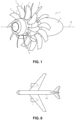
- the engine 1 shown is an “Open Rotor” type engine, in a configuration commonly referred to as “pusher” (i.e. the unducted fan is placed at the rear of the power generator with an air inlet located on the side, to the right on the Figure 1 ).
- the engine 1 comprises a nacelle 2 intended to be fixed to a fuselage of an aircraft 100 and an unducted fan 3 (or propeller).
- the fan 3 comprises two counter-rotating fan rotors 4 and 5.
- the rotors 4 and 5 are rotated relative to the nacelle 2 around the same axis of rotation X (which coincides with a main axis of the engine), in opposite directions.
- the engine 1 is an “Open Rotor” type engine in “pusher” configuration with counter-rotating fan rotors.
- the invention is not limited to this configuration.
- the invention also applies to “Open Rotor” type engines in “puller” configuration (i.e. the fan is placed upstream of the power generator with an air inlet located before, between or just behind the two fan rotors).
- the invention also applies to engines having different architectures, such as an architecture comprising a fan rotor comprising moving blades and a fan stator comprising fixed blades, or a single fan rotor.
- the invention is applicable to turboprop-type architectures (comprising a single fan rotor), as well as to wind turbine rotors.
- the axis of rotation of the rotor of the fan 4, 5 (or of the propeller) is called the X axis.
- the axial direction corresponds to the direction of the X axis and a radial direction is a direction perpendicular to this X axis and passing through it.
- Each blade 7 is rotatably mounted relative to the hub 6 around a respective Y setting axis: this Y setting axis extends in a generally radial direction relative to the X axis.
- internal (respectively, interior) and external (respectively, exterior), respectively, are used with reference to a radial direction so that the internal part or face of an element is closer to the X axis than the external part or face of the same element.
- the blade 7 will thus be defined relative to the X axis of the rotor on which it is intended to be mounted and its Y setting axis.
- chord we will understand here, for a given section of the blade 7 (and therefore for a given point on the Y setting axis), the substantially axial straight line segment which connects the leading edge to the trailing edge of the blade 7.
- each fan rotor 4, 5 comprises a hub 6 (or blade hub) rotatably mounted relative to the nacelle 2 and a plurality of blades 7 fixed to the hub 6.
- the blades 7 extend substantially radially relative to the axis of rotation X of the rotor.
- the fan 3 further comprises an actuating mechanism 8 for collectively modifying the pitch angle of the blades 7 of the rotors, in order to adapt the performance of the engine to the different flight phases.
- each blade 7 comprises an attachment part 9 (or blade hub) arranged at the blade root.
- the attachment part 9 is rotatably mounted relative to the hub 6 around a pitch axis Y. More precisely, the attachment part 9 is rotatably mounted inside a housing 10 formed in the hub 6, by means of balls 11 or other rolling elements.
- the attachment part 9 comprises a wall having an external surface having a revolution shape.
- the external surface has two circular grooves suitable for forming raceways for balls or other rolling elements.
- each blade 7 may comprise a cylindrical blade root configured to be connected directly to the hub 6 via bearings.
- the actuating mechanism 8 comprises for example an actuator 12 comprising a body 13 fixed to the hub 6 and a rod 14 capable of being driven in translation relative to the body 12.
- the actuating mechanism 8 further comprises an annular slide 15 mounted integral with the rod 14 and a pin 16 mounted integral with the attachment part 9.
- the pin 16 is capable of sliding in the slide 15 and of rotating relative to the slide 15, so as to convert a translational movement of the rod 14 into a rotational movement of the attachment part 9, and consequently a rotational movement of the blade 7 relative to the hub 6 around its setting axis Y.
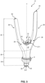
- the blade 7 comprises an aerodynamic profile structure 20 suitable for being placed in an air flow when the engine 1 is operating in order to generate lift, as well as a spar 21.
- the aerodynamic profile structure 20 comprises two skins 22, which are connected to each other and extend generally opposite each other.
- the skins 22 are shaped so as to define together a lower surface, an upper surface, a leading edge and a trailing edge of the blade 7.
- the leading edge is configured to extend opposite the flow of gases entering the engine 1. It corresponds to the front part of an aerodynamic profile which faces the air flow and which divides the air flow into an lower surface flow and an upper surface flow.
- the trailing edge corresponds to the rear part of the aerodynamic profile, where the lower and upper surface flows meet.
- the skins 22 of the aerodynamic profile structure 20 are made from a composite material comprising a fibrous reinforcement 23 (see in particular Figure 2 ) densified by a matrix. They are therefore monolithic and are made from a single piece according to a non-limiting embodiment. In a variant not shown, it is possible to consider a fibrous reinforcement for the intrados and another for the extrados.
- the fibrous reinforcement 23 may be formed from a single-piece fibrous preform with scalable thickness.
- the fibers of the fibrous reinforcement 23 comprise at least one of the following materials: carbon, glass, aramid, polypropylene, and/or ceramic.
- the fibrous reinforcement 23 may comprise woven (two-dimensional or three-dimensional), braided, knitted, or laminated fibrous arrangements.
- the matrix typically comprises an organic material (thermoset, thermoplastic, or elastomer) or a carbon matrix.
- the matrix comprises a plastic material, typically a polymer, for example, epoxy, bismaleimide, or polyimide.
- the spar 21 comprises a blade root portion 24 which extends outside the aerodynamic profile structure 20, a blade portion 25 which is arranged inside the aerodynamic profile structure 20, between the two skins 22 and a stilt portion 26 which extends between the blade root portion 24 and the blade portion 25.
- the blade root portion 24 is configured to be inserted into the hub 6, if necessary by means of an attachment part 9.
- the stilt portion 26 corresponds to the area of the spar 21 which extends between the outlet of the hub 6 (at the bearing surfaces) and the aerodynamic structure 20.
- the blade portion 25 forms, with the aerodynamic profile structure 20, the blade of the blade 7.
- the spar 21 may be made of metal and in a single piece: the blade root portion 24, the blade portion 25 and the stilt portion 26 are therefore monolithic.
- the metallic material of the spar 21 may comprise at least one of the following materials: steel, titanium, a titanium alloy (in particular TA6V, comprising titanium, aluminum, vanadium and traces of carbon, iron, oxygen and nitrogen), a superalloy based on nickel such as Inconel, an aluminum alloy.
- the manufacture of the metal spar 21 can involve several specific processes such as machining, forging, forming, casting or even additive manufacturing (3D printing).
- the spar 21 may comprise a composite material comprising a matrix-densified fiber reinforcement.
- the matrix of the spar 21 typically comprises an organic material (thermosetting, thermoplastic, or elastomer) or a carbon matrix.
- the matrix comprises a plastic material, typically a polymer, for example epoxy, bismaleimide, or polyimide.
- the fibers of the fiber reinforcement of the spar comprise at least one of the following materials: carbon, glass, aramid, polypropylene, and/or ceramic.
- the fiber reinforcement 23 may comprise woven (two-dimensional or three-dimensional), braided, knitted, or laminated fiber arrangements.
- the matrix of the spar 21 and the matrix of the aerofoil structure may, if appropriate, be identical.
- the fibers of the fiber reinforcement of the spar 21 may be made of a material that is the same as or different from the fibers of the fiber reinforcement 23.
- the branches 28 extend radially from a top of the body 27, gradually moving away from the setting axis Y.
- the branches 28 therefore diverge slightly from their radially internal end 29, which is fixed to the body 27, towards their free end 30.
- the distance between the free ends 30 of the branches 28 is therefore greater than the distance between their radially internal ends 29.
- the maximum distance between the free ends 30 of the branches 28 may be between 50% and 80% of the maximum chord of the blade 7, while the maximum distance between the internal radial ends 29 (measured at the counterplate described below) may be between 20% and 50% of the maximum chord.
- the two branches 28 of the spar 21 make it possible to increase the torsional stiffness of the structure of the blade 7 while maintaining a reduced mass.
- Another advantage of this geometry of the spar 21, the branches 28 of which extend radially and in the direction of the chord, is to retain the skins 22 of the aerodynamic profile structure 20 by section restriction. Indeed, under the effect of the centrifugal forces oriented in the radial direction, the skins 22 are pressed against the inclined surfaces of the branches 28. The retention of the skins 22 is therefore not only ensured by the holding of a “weak” interface such as a glue or resin interface which ensures cohesion between two substrates.
- a width (dimension along the chord of the blade 7 for a given height) of each branch 28 is substantially constant, to within 10%, between their radially internal end 29 and their free end 30.
- Their thickness (dimension along an axis normal to the chord for a given height) decreases from their radially internal end 29 towards their free end 30.
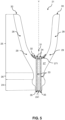
- the geometry of the branches 28 is chosen so as to follow the geometry of the skins 22, and therefore of the blade 7. In other words, when the blade 7 is twisted, the branches 28 can also be twisted so as to follow the geometry of the blade 7 (see for example Figure 4 ).
- the two branches 28 therefore do not necessarily extend in the same plane and preferably follow the camber of the blade 7.
- a height (dimension along the Y-axis) of the blade portion 25 of the spar 21 may be between 20% and 75% of the height of the aerodynamic structure, for example of the order of 35%.
- the spar 21 may comprise a greater number of branches 28.
- the additional branches 28 then extend radially from the body 27.
- the conformation of the spar 21 is adapted to the type of material used.
- the branches 28 can be more extended along the direction of the chord of the blade 7 than in the case of a metal spar 21.
- several fiber reinforcements could be used to produce the spar 21, avoiding machining, and the working section of the spar 21 would be larger than in the case of a metal spar 21.
- the blade root portion 24 may have a bulbous shape, i.e. a generally swollen or domed shape, this swollen or domed shape extending around the setting axis Y. If a median plane passing through the bulb is defined which is normal to the setting axis Y and which passes through its largest cross-section, the bulb of the blade root portion 24 may for example have a generally circular cross-section.
- the spar 21 may be hollow. Alternatively, only a portion of the spar 21 may be hollow (e.g., the branches 28), while the remainder of the spar 21 may be solid. According to yet another alternative, the entire spar 21 is solid.
- the blade 7 further comprises a structural reinforcement 31 extending from the blade root portion 24 to the main body 27 of the blade portion 25.
- This structural reinforcement 31 is in particular secured to the blade root portion 24 in order to form a force path distinct from the spar portion 26 of the spar 21 in the event of rupture of the spar 21 within the spar portion 26. Thanks to this distinct force path, the structural reinforcement 31 thus makes it possible to retain the blade of the vane 7 in the event of breakage of the spar 21 in its stilt portion 26, which is highly stressed.
- the structural reinforcement 31 makes it possible in particular to reduce the risks incurred in the event of the development of one or more fatigue cracks/fissures within the stilt portion 26 or during bird ingestion.
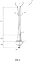
- the structural reinforcement 31 comprises a counterplate 32 fixed to the blade portion 25 so as to come into contact with the body 27, opposite the blade root portion 24.
- the counterplate 32 is generally symmetrical with respect to the setting axis Y and is centered on the setting axis Y.
- the counterplate 32 is pressed against a radially external face 271 of the body 27, between the internal radial ends 29 of the branches 28 of the blade portion 25 of the spar 21.
- the structural reinforcement 31 comprises at least one rod 34 mounted tightly between the blade root portion 24 and the counterplate 32.
- the structural reinforcement 31 comprises two rods 34 mounted in parallel in the spar 21.
- a slot 33 configured to receive a corresponding rod 34 of the structural reinforcement 31 is made in the spar 21.
- Each slot 33 extends generally along the setting axis Y.
- the slots 33 extend symmetrically on either side of the setting axis Y.
- Each slot 33 also extends from the blade root portion 24 to the core of the blade portion 25 and opens both onto a radially internal face 241 of the blade root portion 24 (which corresponds to the face which comes against a bottom of the attachment 9 or the hub 6) and onto the radially external face 271 of the body 27, opposite the counterplate 32.
- the slots 33 are therefore through.
- the rods 34 and the slots 33 are preferably rectilinear in order to facilitate the manufacture and assembly of the blade 7.
- the slots 33 can for example be produced by drilling the spar 21, since the latter is metallic.
- the rods 34 may each comprise a screw 34 which may be fixed to the counterplate 31 using a nut 35.
- the counterplate 32 comprises two through-holes for each receiving a rod 34 and is applied against the radially external face 271 of the body 27 so as to place each through-hole facing the outlet of a corresponding light 33.
- Each screw 34 is then inserted into one of the through-holes and into the corresponding light 33 so that the head of each screw 34 comes to bear against the counterplate 32.
- the free end of each screw 34 then projects from the corresponding light 33.
- a nut 35 is then screwed onto the free end of each screw 34 and is tightened so as to prestress the counterplate 32 by applying pressure to it in the direction of the body 27 (without crushing it for as much).
- the screws 34 and nuts 35 could be mounted in the other direction, the head of the screws 34 then being in contact with the radially internal face 241 of the blade root part 24 while their free end is fixed to the counterplate 32 by the nuts 35.
- the counterplate 32 may comprise a compressible material.
- the counterplate 32 may be made of an elastomer.
- the counterplate 32 may comprise an organic honeycomb, such as a Nomex® type honeycomb (comprising aramid fibers calendered into sheets and covered with phenolic resin), or a honeycomb comprising one of the following materials: poly(p-phenyleneterephthalamide) (Kevlar type), glass fibers, aluminum.
- the counterplate 32 is made of metal, for example of the same material as the spar 21.
- the structural reinforcement 31 is monolithic with the spar 21.
- the structural reinforcement 31 comprises a barrel 36 monolithic with the blade root portion 24 and extending along the setting axis Y through a passage 37 formed in the stilt portion 26 and, optionally, in the body 27 of the blade portion 25.
- the barrel 36 also extends through the body 27.
- the barrel 36 thus forms a portion of the stilt part 26 and of the body part 27. It is monolithic with the blade root part 24. On the other hand, it is separate and distinct from the rest of the stilt part 26 and of the blade part 25 of the spar 21.
- the barrel 36 also projects from the radially external face 271 of the body 27, the counterplate 32 being connected to a free end of the barrel 36.
- the barrel 36 and the counterplate 32 may be monolithic. Alternatively, the counterplate 32 may be attached and fixed to the barrel 36, for example by welding or using fixing members such as screws 34.
- the latter can be made of the same material as the spar 21 (and the barrel 36).
- the monolithic spar 21 with the barrel 36 and, if applicable, the counterplate 32 can be obtained in particular by 3D printing. If applicable, a layer of material compressible can be fixed on the radially internal face of the counterplate 32 and/or the radially external face 271 of the body 27 in order to cushion the impact of the counterplate 32 against the body 27 of the spar 21 at the time of activation of the secondary force path (i.e. in the event of rupture of the stilt part 26).
- the layer of compressible material may, if necessary, also be produced by 3D printing and be monolithic with the counterplate 32 and/or the body 27.
- the layer of compressible material may comprise a foam of organic origin (polyethacrylimide, polyethylene terephthalate (PET), polyvinyl chloride (PVC), polyetherimide (PEI), polyvinyl, carbon, polyisocyanurate, polyurethane, etc.) or metallic (in particular aluminum alloy), or even a honeycomb of the Nomex ® type, Kevlar, fiberglass or even aluminum.
- a foam of organic origin polyethacrylimide, polyethylene terephthalate (PET), polyvinyl chloride (PVC), polyetherimide (PEI), polyvinyl, carbon, polyisocyanurate, polyurethane, etc.
- metallic in particular aluminum alloy
- the passage 37 may be flared in the stilt portion 26 of the spar 21 so as to provide a space 38 around the barrel 36.
- the space 38 may in particular have an annular shape of generally circular section near the blade root portion 24, the section (in a plane normal to the setting axis Y) of the space 38 then decreasing in the direction of the body 27.
- the space 38 may be empty or, as a variant, be completely or partially filled by a filling piece which may comprise internal cavities.
- a section (in a plane normal to the Y-axis) of the barrel 36 is substantially constant in the stilt part 26 and in the body 27, then gradually widens near the counterplate 32.
- the shape of the blade root portion 24 of the spar 21 is unchanged.
- the passage 37 may be formed only in the stilt portion 26 and in the body portion 27 of the spar 21.
- the external shape of the stilt portion 26 and of the blade portion 25 of the spar 21 may be identical whatever the embodiment of the structural reinforcement 31.
- the body 27 of the blade portion 25 is in three parts (see in particular Figure 6 ).
- a first part of the body 27 is formed by the barrel 36 of the structural reinforcement 31.
- the second and third parts correspond to the rest of the body 27 and extend around the barrel 36. These second parts then each extend in the extension of an associated branch 28: they can therefore be separated all along the barrel 36 and only be connected together at the level of the foot part of the spar 21 (see Figure 6 ).
- the blade 7 further comprises a filling piece 39 placed between the two skins 22 of the aerodynamic profile structure 20, between the two branches 28 and the radially external face 271 of the body 27 of the blade part 25 of the spar 21.
- the filling piece 39 serves as a support for the skins 22 of the aerodynamic profile structure 20.
- the filling part 39 can be made of a material comprising internal cavities, such as a foam of organic origin (polyethacrylimide, polyethylene terephthalate (PET), polyvinyl chloride (PVC), polyetherimide (PEl), polyvinyl, carbon, polyisocyanurate, polyurethane, etc.) or metallic (in particular aluminum alloy), or even a honeycomb of the Nomex ® type, Kevlar, fiberglass or even aluminum.
- a foam of organic origin polyethacrylimide, polyethylene terephthalate (PET), polyvinyl chloride (PVC), polyetherimide (PEl), polyvinyl, carbon, polyisocyanurate, polyurethane, etc.
- metallic in particular aluminum alloy
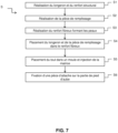
- a blade 7 according to the invention can be obtained in accordance with the following steps.
- the spar 21 and the structural reinforcement 31 are manufactured.
- Any conventional method can be used here, including machining, forging, forming, casting or even additive manufacturing (3D printing) for the production of the spar 21.
- the slot(s) 33 are made in the spar 21, for example by machining.
- the counterplate 32 previously machined, is applied to the radially external face 271 of the body 27, then a rod 34, typically a screw 34, is inserted into each orifice and each associated slot 33.
- a nut 35 is then screwed onto the free end of each rod 34 so as to block the rod(s) 34 and the counterplate 32 relative to the spar 21 and to prestress the counterplate 32.
- the structural reinforcement 31 can be produced simultaneously with the manufacture of the spar 21.
- the structural reinforcement 31 and the spar 21 are then obtained by 3D printing and are monolithic.
- the fiber reinforcement can be produced by three-dimensional weaving on a jacquard-type loom. During weaving, bundles of warp strands (or warp strands) are arranged in several layers. Weft strands T are interlaced with the warp strands C so as to bind the different layers of warp strands C together.
- the three-dimensional weaving can be an “interlock” weave. “Interlock” means a weaving weave in which each layer of weft strands binds several layers of warp strands with all the strands of the same weft column having the same movement in the plane of the weave.
- the branches 28 can for example be obtained by making a delinking at the radially external face 271 of the body 27.
- a filling piece 39 is produced and placed between the two branches 28 of the spar 21 and placed in abutment against the blade part 25 of the spar 21. If necessary, a film of glue can be applied to the interface between the filling piece 39 and the spar 21.
- the filling piece 39 can be produced by injecting a foam between the branches 28 of the spar 21 or by adding and fixing a previously machined filling piece 39.
- the filling part 39 can be obtained simultaneously with step S1 by 3D printing (in particular when it is metallic).
- the filling part 39, the structural reinforcement 31 and the spar 21 can then be monolithic.
- the fiber reinforcement 23 of the aerodynamic profile structure 20 is produced.
- the fiber reinforcement 23 can be produced by three-dimensional weaving on a jacquard loom. During weaving, bundles of warp strands (or warp strands) are arranged in several layers. Weft strands T are interlaced with the warp strands C so as to bind the different layers of warp strands C together.
- the three-dimensional weaving can be an “interlock” weave. “Interlock” means a weaving weave in which each layer of weft strands binds several layers of warp strands with all the strands of the same weft column having the same movement in the plane of the weave.
- a delinking is carried out in the fiber reinforcement 23.
- the delinking can be carried out at the head (opposite the blade root 7), at the leading edge or the trailing edge of the blade 7.
- the delinked zone is obtained by not connecting the warp strands of two successive layers in two distinct locations separated by the weft strands.
- the fibrous reinforcement 23 is then shaped (three-dimensional deformation in order to give it a twisted shape corresponding to its final shape).
- the fiber reinforcement 23 of the aerofoil structure 20 may comprise a two-dimensional woven, braided, knitted, or laminated fiber arrangement.
- the fiber reinforcement 23 of the skins 22 of the aerofoil structure 20 may comprise a pre-impregnated laminated composite material. In this embodiment variant, it is then not necessary to perform a debonding.
- the fiber reinforcement 23 of the aerodynamic profile structure 20 is placed around the spar 21 and the filler part 39 so that the blade root portion 24 and the stilt portion 26 are located outside the fiber reinforcement 23 and the blade portion 25 is located inside the fiber reinforcement 23.
- the spar 21 and the filling piece 39 are advantageously inserted by the separation of the fiber reinforcement, typically from the top when the separation is produced at the blade head 7.
- the prepreg composite material sheets can be laminated onto the spar 21 and the filler piece 39.
- the assembly thus obtained, formed of the spar 21, the fiber reinforcement 23 of the aerodynamic profile structure 20 and the filling part 39 is placed in a mold having a cavity having the shape of the final molded part (namely the blade 7) and the plastic material (the “matrix” of the aerodynamic profile structure) is injected into the mold so as to impregnate the fiber reinforcement 23.
- the injection of plastic material can be carried out by an injection technique of the RTM or VARRTM type.
- the injected plastic material is for example a thermosetting liquid composition containing an organic precursor of the matrix material.
- the organic precursor is usually in the form of a polymer, such as a resin, possibly diluted in a solvent.
- the plastic material is heated so as to cause polymerization of the plastic material, for example by crosslinking.
- the mold is placed in an oven.
- the part obtained is then demolded and then, optionally, machined to remove excess lengths and obtain a part having the desired shape, despite possible shrinkage of the fibers of the fibrous reinforcement 23 during the polymerization of the plastic material.
- an attachment part 9 may, if necessary, be added and fixed to the root of the blade 7, around the blade root portion 24 of the spar 21. It may in particular be obtained by machining in order to form the cavity whose shape and dimensions correspond to those of the blade root portion 24.
- the attachment part 9 may be made in two parts so that it can be added and fixed around the blade root portion 24 using two dedicated rings, for example by shrinking, screwing, welding or even using a clamp. Step S6 of fixing the attachment part 9 may therefore be carried out before or after the injection (step S5).
- the material constituting the attachment part 9 may be different from that of the spar 21.
- the invention thus allows the blade 7 to withstand the mechanical loads encountered during the flight phases which are likely to excite the vibration modes of the blade 7.
- the production of the metal spar 21 also makes it possible to obtain a thin aerodynamic profile at the bottom of the blade, making it possible to correctly supply the low-pressure compressor downstream of the fan with a conventional annular air inlet sleeve and to avoid the use of an offset sector sleeve.
- the retention of the skins 22 of the aerodynamic profile structure is ensured not only by the matrix injected into the fiber reinforcement after insertion of the spar 21, but also by restriction of section around the metal spar 21. From a mechanical point of view, the use of such a metal spar 21 is also advantageous in terms of torsional stiffness compared to its limited mass.
Landscapes
- Engineering & Computer Science (AREA)
- Mechanical Engineering (AREA)
- General Engineering & Computer Science (AREA)
- Chemical & Material Sciences (AREA)
- Composite Materials (AREA)
- Materials Engineering (AREA)
- Architecture (AREA)
- Physics & Mathematics (AREA)
- Fluid Mechanics (AREA)
- Aviation & Aerospace Engineering (AREA)
- Structures Of Non-Positive Displacement Pumps (AREA)
- Turbine Rotor Nozzle Sealing (AREA)
Claims (15)
- Schaufel (7) einer Turbomaschine, umfassend:- eine Struktur mit aerodynamischem Profil (20), die zwei einander gegenüberliegende Häute (22) umfasst, wobei die Häute (22) eine durch eine Matrix verdichtete Faserverstärkung (23) umfassen; und- einen Holm (21) mit einem Schaufelfußteil (24), das so konfiguriert ist, dass es auf eine Nabe eines Rotors der Turbomaschine montiert werden kann, einem Blattteil (25), das im Innern der Struktur mit aerodynamischem Profil (20) zwischen den beiden Häuten (22) angeordnet ist, und einem Stelzenteil (26), das sich außerhalb der Struktur mit aerodynamischem Profil (20) zwischen dem Schaufelfußteil (24) und dem Blattteil (25) erstreckt,wobei das Blattteil (25) einen mit dem Schaufelfußteil (24) verbundenen Körper (27) und zwei sich radial von dem Körper (27) aus erstreckende Schenkel umfasst;wobei die Schaufel (7) dadurch gekennzeichnet ist, dass sie außerdem eine strukturelle Verstärkung (31) umfasst, die sich von dem Schaufelfußteil (24) bis zu dem Körper (27) des Blattteils (25) erstreckt, wobei die strukturelle Verstärkung (31) fest mit dem Schaufelfußteil (24) verbunden ist und so konfiguriert ist, dass sie im Falle eines Bruchs des Holms (21) innerhalb des Stelzenteils (26) einen von dem Stelzenteil (26) getrennten Kraftpfad bildet.
- Schaufel (7) nach Anspruch 1, wobei die strukturelle Verstärkung (31) eine Gegenplatte (32) umfasst, die so an dem Blattteil (25) befestigt ist, dass sie mit dem Körper (27) gegenüber dem Schaufelfußteil (24) in Kontakt kommt.
- Schaufel (7) nach Anspruch 2, wobei die strukturelle Verstärkung (31) mindestens eine zwischen dem Schaufelfußteil (24) und der Gegenplatte (32) eingepresste Stange (34), vorzugsweise zwei parallele Stangen (34), umfasst.
- Schaufel (7) nach Anspruch 3, wobei die mindestens eine Stange (34) in eine durchgehende Öffnung (33) eingesetzt ist, die in eine radial innere Fläche (241) des Schaufelfußteils (24) mündet.
- Schaufel (7) nach einem der Ansprüche 3 und 4, wobei die mindestens eine Stange (34) geradlinig ist.
- Schaufel (7) nach einem der Ansprüche 1 und 2, wobei die strukturelle Verstärkung (31) einen Schaft (36) umfasst, der monolithisch mit dem Schaufelfußteil (24) ist und sich durch einen Durchgang (37) erstreckt, der in dem Stelzenteil (26) und gegebenenfalls dem Körper (27) des Blattteils (25) ausgebildet ist.
- Schaufel (7) nach Anspruch 6 in Kombination mit Anspruch 2, wobei die Gegenplatte (32) mit einem Ende des Schaftes (36) verbunden ist.
- Schaufel (7) nach einem der Ansprüche 6 und 7, wobei der Durchgang (37) in dem Stelzenteil (26) des Holms (21) derart aufgeweitet ist, dass ein ringförmiger Raum (38) um den Schaft (36) in dem Stelzenteil (26) geschaffen wird.
- Schaufel (7) nach einem der Ansprüche 1 bis 8, wobei der Holm (21) aus Metall ist.
- Schaufel (7) nach einem der Ansprüche 1 bis 9, die weiter ein Füllelement (39) mit inneren Hohlräumen umfasst, das in der Struktur mit aerodynamischem Profil (20) zwischen den beiden Schenkeln (28) des Blattteils (25) angeordnet ist.
- Gebläse (3) mit einer Nabe (6) und sich radial von der Nabe (6) aus erstreckenden Schaufeln (7) nach einem der Ansprüche 1 bis 10, wobei jede Schaufel (7) relativ zu der Nabe drehbar um eine jeweilige Stellachse (Y) montiert ist.
- Gasturbinentriebwerk (1) mit einem Gebläse (3) nach Anspruch 11 und einem Betätigungsmechanismus (8), der so gesteuert werden kann, dass sich die Schaufeln (7) so um Stellachsen (Y) drehen, dass ein Stellwinkel der Schaufeln (7) verändert wird.
- Flugzeug (100) mit mindestens einem Gasturbinentriebwerk (1) nach Anspruch 12.
- Verfahren zur Herstellung einer Schaufel (7) nach einem der Ansprüche 1 bis 10, umfassend die folgenden Schritte:S1: Erstellen des Holms (21) und der strukturellen Verstärkung (31);S3: Erstellen der Faserverstärkung der Struktur mit aerodynamischem Profil (20), beispielsweise durch dreidimensionales Weben;S4: Einsetzen des Holms (21) in die Faserverstärkung (23), so dass sich das Schaufelfußteil (24) außerhalb der ersten Faserverstärkung (23) und das Blattteil (25) innerhalb der ersten Faserverstärkung (23) befindet; undS5: Platzieren der aus der ersten Faserverstärkung (23) und der zweiten Faserverstärkung (26) gebildeten Anordnung in einer Form und Einspritzen einer Matrize in die Anordnung, um die Schaufel (7) zu erhalten.
- Verfahren nach Anspruch 14, das ferner vor dem Schritt S4 einen Schritt des Positionierens (S2) eines Füllelements, das aus einem Material erstellt ist, das innere Hohlräume zwischen den Schenkeln (28) des Blattteils (25) des Holms (21) aufweist, umfasst.
Applications Claiming Priority (2)
| Application Number | Priority Date | Filing Date | Title |
|---|---|---|---|
| FR2103278A FR3121474B1 (fr) | 2021-03-30 | 2021-03-30 | Aube comprenant une structure en matériau composite et procédé de fabrication associé |
| PCT/FR2022/050549 WO2022208002A1 (fr) | 2021-03-30 | 2022-03-24 | Aube comprenant une structure en matériau composite et procédé de fabrication associé |
Publications (2)
| Publication Number | Publication Date |
|---|---|
| EP4313574A1 EP4313574A1 (de) | 2024-02-07 |
| EP4313574B1 true EP4313574B1 (de) | 2025-04-23 |
Family
ID=75850361
Family Applications (1)
| Application Number | Title | Priority Date | Filing Date |
|---|---|---|---|
| EP22717228.5A Active EP4313574B1 (de) | 2021-03-30 | 2022-03-24 | Schaufel mit einer struktur aus verbundmaterial und entsprechendes herstellungsverfahren |
Country Status (5)
| Country | Link |
|---|---|
| US (1) | US12091986B2 (de) |
| EP (1) | EP4313574B1 (de) |
| CN (1) | CN117222517A (de) |
| FR (1) | FR3121474B1 (de) |
| WO (1) | WO2022208002A1 (de) |
Families Citing this family (11)
| Publication number | Priority date | Publication date | Assignee | Title |
|---|---|---|---|---|
| EP4368377A1 (de) * | 2022-11-10 | 2024-05-15 | Schaad Balass Menzl & Partner AG | Verfahren zur herstellung eines rotorblattes für eine windkraftanlage |
| US12031453B1 (en) * | 2022-12-22 | 2024-07-09 | General Electric Company | Component with spar assembly for a turbine engine |
| FR3147587B1 (fr) | 2023-04-06 | 2025-09-05 | Safran Aircraft Engines | Aube à longeron paramétrique creux et à double portée conique |
| FR3149861A1 (fr) | 2023-06-15 | 2024-12-20 | Safran Aircraft Engines | Ensemble propulsif pour aéronef pourvu d’une hélice et d’un dispositif de calage cyclique des aubes de l’hélice et procédé de régulation du calage cyclique des aubes de l’hélice |
| FR3152039A1 (fr) | 2023-08-11 | 2025-02-14 | Safran Aircraft Engines | aube de turbomachine monobloc |
| FR3153768A1 (fr) * | 2023-10-10 | 2025-04-11 | Safran | Procédé de fabrication d’une aube ou d’une hélice avec média élastomère |
| FR3154142A1 (fr) * | 2023-10-11 | 2025-04-18 | Safran | Aube de rotor pour une turbomachine |
| FR3154462B1 (fr) * | 2023-10-19 | 2025-09-26 | Safran Aircraft Engines | Aube a calage variable pour une helice de turbomachine d’aeronef |
| FR3158537A1 (fr) * | 2024-01-22 | 2025-07-25 | Safran Aircraft Engines | Aube composite de turbomachine comprenant un pied d’aube monolithique |
| EP4603379A1 (de) * | 2024-02-14 | 2025-08-20 | General Electric Company | Verbundschaufelanordnung mit einer verbundschaufel und holm |
| FR3162474A1 (fr) | 2024-05-27 | 2025-11-28 | Safran Aircraft Engines | Aube en materiau composite comprenant une structure fibreuse |
Family Cites Families (13)
| Publication number | Priority date | Publication date | Assignee | Title |
|---|---|---|---|---|
| US3981616A (en) * | 1974-10-22 | 1976-09-21 | The United States Of America As Represented By The Secretary Of The Air Force | Hollow composite compressor blade |
| US4524499A (en) * | 1981-11-16 | 1985-06-25 | Trw Inc. | Method of fabricating an aircraft propeller assembly with composite blades |
| FR2740378B1 (fr) * | 1995-10-30 | 1998-01-02 | Eurocopter France | Procede de fabrication d'une pale a pas variable en materiau composite pour rotor d'helicoptere, et pale a pas variable pouvant etre obtenue par un tel procede |
| US7758314B2 (en) * | 2003-03-12 | 2010-07-20 | Florida Turbine Technologies, Inc. | Tungsten shell for a spar and shell turbine vane |
| FR2887601B1 (fr) | 2005-06-24 | 2007-10-05 | Snecma Moteurs Sa | Piece mecanique et procede de fabrication d'une telle piece |
| US8142163B1 (en) * | 2008-02-01 | 2012-03-27 | Florida Turbine Technologies, Inc. | Turbine blade with spar and shell |
| FR2954271B1 (fr) * | 2009-12-21 | 2012-02-17 | Snecma | Pale d'helice d'aeronef |
| FR2962175B1 (fr) | 2010-07-02 | 2012-08-10 | Snecma | Aube a longeron composite integre |
| FR2963055B1 (fr) * | 2010-07-21 | 2014-01-31 | Snecma | Aube de rotor d'un turbomoteur a gaz en materiau composite comprenant une chape de liaison, procede de fabrication de l'aube |
| FR2975123B1 (fr) * | 2011-05-13 | 2013-06-14 | Snecma Propulsion Solide | Rotor de turbomachine comprenant des aubes en materiau composite avec talon rapporte |
| FR2982175B1 (fr) | 2011-11-07 | 2015-06-12 | Sita Bioenergies | Installation d'epuration de biogaz, procede de traitement de biogaz et utilisation de machefers pour un tel traitement. |
| US20140377072A1 (en) * | 2013-06-24 | 2014-12-25 | General Electric Company | Root stiffener for a wind turbine rotor blade |
| EP2977549B1 (de) * | 2014-07-22 | 2017-05-31 | Safran Aero Boosters SA | Beschaufelung einer axialen strömungsmaschine und zugehörige turbomachine |
-
2021
- 2021-03-30 FR FR2103278A patent/FR3121474B1/fr active Active
-
2022
- 2022-03-24 CN CN202280031562.5A patent/CN117222517A/zh active Pending
- 2022-03-24 US US18/285,122 patent/US12091986B2/en active Active
- 2022-03-24 EP EP22717228.5A patent/EP4313574B1/de active Active
- 2022-03-24 WO PCT/FR2022/050549 patent/WO2022208002A1/fr not_active Ceased
Also Published As
| Publication number | Publication date |
|---|---|
| US12091986B2 (en) | 2024-09-17 |
| WO2022208002A1 (fr) | 2022-10-06 |
| FR3121474B1 (fr) | 2023-02-17 |
| FR3121474A1 (fr) | 2022-10-07 |
| EP4313574A1 (de) | 2024-02-07 |
| US20240175363A1 (en) | 2024-05-30 |
| CN117222517A (zh) | 2023-12-12 |
Similar Documents
| Publication | Publication Date | Title |
|---|---|---|
| EP4313574B1 (de) | Schaufel mit einer struktur aus verbundmaterial und entsprechendes herstellungsverfahren | |
| EP4301657B1 (de) | Schaufel mit einer struktur aus verbundwerkstoff und zugehöriges herstellungsverfahren | |
| FR3080322A1 (fr) | Aube comprenant une structure en materiau composite et procede de fabrication associe | |
| EP4093670B1 (de) | Schaufel mit verbundwerkstoffstruktur und zugehöriges herstellungsverfahren | |
| EP4117895B1 (de) | Rotorblatt mit verbundstoffstruktur und verfahren zu seiner herstellung | |
| WO2021123652A9 (fr) | Aube de soufflante ou d'helice pour une turbomachine d'aeronef et son procede de fabrication | |
| BE1023290B1 (fr) | Aube composite de compresseur de turbomachine axiale | |
| FR3108144A1 (fr) | Aube comprenant une structure en matériau composite et procédé de fabrication associé | |
| EP3996990B1 (de) | Propellerblatt | |
| FR3115071A1 (fr) | Aube composite et attache de pied d’aube anti-rotation | |
| FR3087831A1 (fr) | Aube comprenant une structure en materiau composite et une piece de raidissement metallique | |
| WO2025027258A1 (fr) | Aube comprenant une structure en matériau composite et un longeron métallique | |
| FR3140915A1 (fr) | Aube à calage variable pour soufflante de turbomachine présentant un gradient de raideur dans le pied | |
| EP4532319B1 (de) | Schaufel mit einer struktur aus verbundstoff und zugehöriges herstellungsverfahren | |
| FR3152536A1 (fr) | Aube à calage variable comportant une zone de centrage et de rétention | |
| FR3158537A1 (fr) | Aube composite de turbomachine comprenant un pied d’aube monolithique | |
| FR3155458A1 (fr) | Bouchons solubles pour création de cavité borgne dans un aubage composite | |
| FR3155560A1 (fr) | Aube creuse avec raidisseurs en résine en curviligne | |
| FR3162474A1 (fr) | Aube en materiau composite comprenant une structure fibreuse | |
| FR3132079A1 (fr) | Longeron pour une aube de turbomoteur d’aéronef à structure composite | |
| FR3151883A1 (fr) | Aubage fixe de turbomachine comprenant des aubes à calage variable | |
| FR3154462A1 (fr) | Aube a calage variable pour une helice de turbomachine d’aeronef | |
| FR3092270A1 (fr) | Aube comprenant une structure en materiau composite et procede de fabrication associe |
Legal Events
| Date | Code | Title | Description |
|---|---|---|---|
| STAA | Information on the status of an ep patent application or granted ep patent |
Free format text: STATUS: UNKNOWN |
|
| STAA | Information on the status of an ep patent application or granted ep patent |
Free format text: STATUS: THE INTERNATIONAL PUBLICATION HAS BEEN MADE |
|
| PUAI | Public reference made under article 153(3) epc to a published international application that has entered the european phase |
Free format text: ORIGINAL CODE: 0009012 |
|
| STAA | Information on the status of an ep patent application or granted ep patent |
Free format text: STATUS: REQUEST FOR EXAMINATION WAS MADE |
|
| 17P | Request for examination filed |
Effective date: 20231023 |
|
| AK | Designated contracting states |
Kind code of ref document: A1 Designated state(s): AL AT BE BG CH CY CZ DE DK EE ES FI FR GB GR HR HU IE IS IT LI LT LU LV MC MK MT NL NO PL PT RO RS SE SI SK SM TR |
|
| DAV | Request for validation of the european patent (deleted) | ||
| DAX | Request for extension of the european patent (deleted) | ||
| GRAP | Despatch of communication of intention to grant a patent |
Free format text: ORIGINAL CODE: EPIDOSNIGR1 |
|
| STAA | Information on the status of an ep patent application or granted ep patent |
Free format text: STATUS: GRANT OF PATENT IS INTENDED |
|
| INTG | Intention to grant announced |
Effective date: 20241106 |
|
| GRAS | Grant fee paid |
Free format text: ORIGINAL CODE: EPIDOSNIGR3 |
|
| GRAA | (expected) grant |
Free format text: ORIGINAL CODE: 0009210 |
|
| STAA | Information on the status of an ep patent application or granted ep patent |
Free format text: STATUS: THE PATENT HAS BEEN GRANTED |
|
| AK | Designated contracting states |
Kind code of ref document: B1 Designated state(s): AL AT BE BG CH CY CZ DE DK EE ES FI FR GB GR HR HU IE IS IT LI LT LU LV MC MK MT NL NO PL PT RO RS SE SI SK SM TR |
|
| REG | Reference to a national code |
Ref country code: GB Ref legal event code: FG4D Free format text: NOT ENGLISH |
|
| REG | Reference to a national code |
Ref country code: CH Ref legal event code: EP |
|
| REG | Reference to a national code |
Ref country code: DE Ref legal event code: R096 Ref document number: 602022013569 Country of ref document: DE |
|
| REG | Reference to a national code |
Ref country code: IE Ref legal event code: FG4D Free format text: LANGUAGE OF EP DOCUMENT: FRENCH |
|
| REG | Reference to a national code |
Ref country code: NL Ref legal event code: MP Effective date: 20250423 |
|
| PG25 | Lapsed in a contracting state [announced via postgrant information from national office to epo] |
Ref country code: NL Free format text: LAPSE BECAUSE OF FAILURE TO SUBMIT A TRANSLATION OF THE DESCRIPTION OR TO PAY THE FEE WITHIN THE PRESCRIBED TIME-LIMIT Effective date: 20250423 |
|
| REG | Reference to a national code |
Ref country code: AT Ref legal event code: MK05 Ref document number: 1787409 Country of ref document: AT Kind code of ref document: T Effective date: 20250423 |
|
| PG25 | Lapsed in a contracting state [announced via postgrant information from national office to epo] |
Ref country code: FI Free format text: LAPSE BECAUSE OF FAILURE TO SUBMIT A TRANSLATION OF THE DESCRIPTION OR TO PAY THE FEE WITHIN THE PRESCRIBED TIME-LIMIT Effective date: 20250423 Ref country code: PT Free format text: LAPSE BECAUSE OF FAILURE TO SUBMIT A TRANSLATION OF THE DESCRIPTION OR TO PAY THE FEE WITHIN THE PRESCRIBED TIME-LIMIT Effective date: 20250825 Ref country code: ES Free format text: LAPSE BECAUSE OF FAILURE TO SUBMIT A TRANSLATION OF THE DESCRIPTION OR TO PAY THE FEE WITHIN THE PRESCRIBED TIME-LIMIT Effective date: 20250423 |
|
| REG | Reference to a national code |
Ref country code: LT Ref legal event code: MG9D |
|
| PG25 | Lapsed in a contracting state [announced via postgrant information from national office to epo] |
Ref country code: GR Free format text: LAPSE BECAUSE OF FAILURE TO SUBMIT A TRANSLATION OF THE DESCRIPTION OR TO PAY THE FEE WITHIN THE PRESCRIBED TIME-LIMIT Effective date: 20250724 Ref country code: NO Free format text: LAPSE BECAUSE OF FAILURE TO SUBMIT A TRANSLATION OF THE DESCRIPTION OR TO PAY THE FEE WITHIN THE PRESCRIBED TIME-LIMIT Effective date: 20250723 |
|
| PG25 | Lapsed in a contracting state [announced via postgrant information from national office to epo] |
Ref country code: PL Free format text: LAPSE BECAUSE OF FAILURE TO SUBMIT A TRANSLATION OF THE DESCRIPTION OR TO PAY THE FEE WITHIN THE PRESCRIBED TIME-LIMIT Effective date: 20250423 |
|
| PG25 | Lapsed in a contracting state [announced via postgrant information from national office to epo] |
Ref country code: BG Free format text: LAPSE BECAUSE OF FAILURE TO SUBMIT A TRANSLATION OF THE DESCRIPTION OR TO PAY THE FEE WITHIN THE PRESCRIBED TIME-LIMIT Effective date: 20250423 |
|
| PG25 | Lapsed in a contracting state [announced via postgrant information from national office to epo] |
Ref country code: HR Free format text: LAPSE BECAUSE OF FAILURE TO SUBMIT A TRANSLATION OF THE DESCRIPTION OR TO PAY THE FEE WITHIN THE PRESCRIBED TIME-LIMIT Effective date: 20250423 |
|
| PG25 | Lapsed in a contracting state [announced via postgrant information from national office to epo] |
Ref country code: AT Free format text: LAPSE BECAUSE OF FAILURE TO SUBMIT A TRANSLATION OF THE DESCRIPTION OR TO PAY THE FEE WITHIN THE PRESCRIBED TIME-LIMIT Effective date: 20250423 |
|
| PG25 | Lapsed in a contracting state [announced via postgrant information from national office to epo] |
Ref country code: RS Free format text: LAPSE BECAUSE OF FAILURE TO SUBMIT A TRANSLATION OF THE DESCRIPTION OR TO PAY THE FEE WITHIN THE PRESCRIBED TIME-LIMIT Effective date: 20250723 |
|
| PG25 | Lapsed in a contracting state [announced via postgrant information from national office to epo] |
Ref country code: IS Free format text: LAPSE BECAUSE OF FAILURE TO SUBMIT A TRANSLATION OF THE DESCRIPTION OR TO PAY THE FEE WITHIN THE PRESCRIBED TIME-LIMIT Effective date: 20250823 |
|
| PG25 | Lapsed in a contracting state [announced via postgrant information from national office to epo] |
Ref country code: LV Free format text: LAPSE BECAUSE OF FAILURE TO SUBMIT A TRANSLATION OF THE DESCRIPTION OR TO PAY THE FEE WITHIN THE PRESCRIBED TIME-LIMIT Effective date: 20250423 |
|
| PG25 | Lapsed in a contracting state [announced via postgrant information from national office to epo] |
Ref country code: SM Free format text: LAPSE BECAUSE OF FAILURE TO SUBMIT A TRANSLATION OF THE DESCRIPTION OR TO PAY THE FEE WITHIN THE PRESCRIBED TIME-LIMIT Effective date: 20250423 Ref country code: DK Free format text: LAPSE BECAUSE OF FAILURE TO SUBMIT A TRANSLATION OF THE DESCRIPTION OR TO PAY THE FEE WITHIN THE PRESCRIBED TIME-LIMIT Effective date: 20250423 |
|
| PG25 | Lapsed in a contracting state [announced via postgrant information from national office to epo] |
Ref country code: CZ Free format text: LAPSE BECAUSE OF FAILURE TO SUBMIT A TRANSLATION OF THE DESCRIPTION OR TO PAY THE FEE WITHIN THE PRESCRIBED TIME-LIMIT Effective date: 20250423 |
|
| PG25 | Lapsed in a contracting state [announced via postgrant information from national office to epo] |
Ref country code: EE Free format text: LAPSE BECAUSE OF FAILURE TO SUBMIT A TRANSLATION OF THE DESCRIPTION OR TO PAY THE FEE WITHIN THE PRESCRIBED TIME-LIMIT Effective date: 20250423 |
|
| PG25 | Lapsed in a contracting state [announced via postgrant information from national office to epo] |
Ref country code: SK Free format text: LAPSE BECAUSE OF FAILURE TO SUBMIT A TRANSLATION OF THE DESCRIPTION OR TO PAY THE FEE WITHIN THE PRESCRIBED TIME-LIMIT Effective date: 20250423 |
|
| PG25 | Lapsed in a contracting state [announced via postgrant information from national office to epo] |
Ref country code: IT Free format text: LAPSE BECAUSE OF FAILURE TO SUBMIT A TRANSLATION OF THE DESCRIPTION OR TO PAY THE FEE WITHIN THE PRESCRIBED TIME-LIMIT Effective date: 20250423 |