EP4312702B1 - Ensemble soupape de sécurité amélioré pour tuyaux d'entrée d'eau de machines à laver et de lave-vaisselle - Google Patents
Ensemble soupape de sécurité amélioré pour tuyaux d'entrée d'eau de machines à laver et de lave-vaisselle Download PDFInfo
- Publication number
- EP4312702B1 EP4312702B1 EP22724503.2A EP22724503A EP4312702B1 EP 4312702 B1 EP4312702 B1 EP 4312702B1 EP 22724503 A EP22724503 A EP 22724503A EP 4312702 B1 EP4312702 B1 EP 4312702B1
- Authority
- EP
- European Patent Office
- Prior art keywords
- valve
- valve assembly
- shank
- filter
- water inlet
- Prior art date
- Legal status (The legal status is an assumption and is not a legal conclusion. Google has not performed a legal analysis and makes no representation as to the accuracy of the status listed.)
- Active
Links
- XLYOFNOQVPJJNP-UHFFFAOYSA-N water Substances O XLYOFNOQVPJJNP-UHFFFAOYSA-N 0.000 title claims description 34
- 238000005406 washing Methods 0.000 title claims description 5
- 238000004891 communication Methods 0.000 claims description 9
- 239000012530 fluid Substances 0.000 claims description 8
- 239000012528 membrane Substances 0.000 claims description 8
- 239000004743 Polypropylene Substances 0.000 claims description 6
- -1 polypropylene Polymers 0.000 claims description 6
- 229920001155 polypropylene Polymers 0.000 claims description 6
- 239000000463 material Substances 0.000 claims description 5
- 238000002347 injection Methods 0.000 claims description 4
- 239000007924 injection Substances 0.000 claims description 4
- 239000004033 plastic Substances 0.000 claims description 4
- 235000001674 Agaricus brunnescens Nutrition 0.000 claims description 3
- 230000008878 coupling Effects 0.000 claims description 2
- 238000010168 coupling process Methods 0.000 claims description 2
- 238000005859 coupling reaction Methods 0.000 claims description 2
- 239000000835 fiber Substances 0.000 claims description 2
- 238000001914 filtration Methods 0.000 claims description 2
- 238000007789 sealing Methods 0.000 claims description 2
- 230000007246 mechanism Effects 0.000 description 13
- 230000008901 benefit Effects 0.000 description 5
- BGPVFRJUHWVFKM-UHFFFAOYSA-N N1=C2C=CC=CC2=[N+]([O-])C1(CC1)CCC21N=C1C=CC=CC1=[N+]2[O-] Chemical compound N1=C2C=CC=CC2=[N+]([O-])C1(CC1)CCC21N=C1C=CC=CC1=[N+]2[O-] BGPVFRJUHWVFKM-UHFFFAOYSA-N 0.000 description 3
- 238000004519 manufacturing process Methods 0.000 description 3
- 238000013037 co-molding Methods 0.000 description 2
- 239000007788 liquid Substances 0.000 description 2
- 230000009471 action Effects 0.000 description 1
- 238000010276 construction Methods 0.000 description 1
- 230000006872 improvement Effects 0.000 description 1
- 238000000034 method Methods 0.000 description 1
- 230000008569 process Effects 0.000 description 1
- 238000003466 welding Methods 0.000 description 1
Images


Classifications
-
- D—TEXTILES; PAPER
- D06—TREATMENT OF TEXTILES OR THE LIKE; LAUNDERING; FLEXIBLE MATERIALS NOT OTHERWISE PROVIDED FOR
- D06F—LAUNDERING, DRYING, IRONING, PRESSING OR FOLDING TEXTILE ARTICLES
- D06F39/00—Details of washing machines not specific to a single type of machines covered by groups D06F9/00 - D06F27/00
- D06F39/08—Liquid supply or discharge arrangements
- D06F39/081—Safety arrangements for preventing water damage
-
- A—HUMAN NECESSITIES
- A47—FURNITURE; DOMESTIC ARTICLES OR APPLIANCES; COFFEE MILLS; SPICE MILLS; SUCTION CLEANERS IN GENERAL
- A47L—DOMESTIC WASHING OR CLEANING; SUCTION CLEANERS IN GENERAL
- A47L15/00—Washing or rinsing machines for crockery or tableware
- A47L15/42—Details
- A47L15/4214—Water supply, recirculation or discharge arrangements; Devices therefor
- A47L15/4217—Fittings for water supply, e.g. valves or plumbing means to connect to cold or warm water lines, aquastops
Definitions
- the present invention relates to an improved safety valve assembly for water inlet hoses of washing machines and dishwashers.
- the inlet hose of a washing machine or dishwasher is generally equipped with a safety device adapted to block the water flow in the event of a leak from the hose.
- a typical known safety device generally comprises a valve assembly applied to the water inlet faucet and a corrugated sheath which covers the inlet hose and which is hermetically closed on the valve assembly and on the fitting which is applied to the household appliance.
- US 2011/036436 A1 describes a water conducting household appliance.
- EP 1 798 326 A1 illustrates an anti-flooding safety device for household appliances.
- WO 2020/012517 A1 describes an anti-flooding duct provided with a safety valve for supplying water.
- EP 3 553 222 A1 relates to an anti-flooding safety device for a washing machine.
- US 2018/273399 A1 concerns a hydraulic control device for utility apparatuses.
- the aim of the present invention is to provide a valve assembly which is improved compared to the systems of the prior art described above and which is more compact and functionally superior.
- Another object of the invention is to provide a valve assembly which can be made with a small number of components, facilitating the production process.
- a further object of the invention is to provide a valve assembly equipped with a new and advantageous filter fixing system.
- Another object of the invention is to provide a valve assembly equipped with a non-return valve.
- a further object of the invention is to provide a valve assembly in which, with the mechanism in rest condition, i.e. in the regular use position, the water flow rate is higher than in the safety devices of the known type.
- Another object of the invention is to provide a valve assembly equipped with a mechanism of a type that, when it intervenes, can block the water flow even while water is still flowing, which is not possible with the known devices.
- a further object of the invention is to provide a valve assembly in which the intervention of the mechanism is repeatable, thereby providing the possibility of testing completely (100%) the valve assembly.
- Another object of the invention is to provide a valve assembly constructed with a smaller number of components than in the known devices and which is therefore also cheaper.
- a further object of the invention is to provide a valve assembly, the assembly of which is simpler than the known devices, thus allowing a less complicated automation and therefore more economical in terms of production.
- a further object of the present invention is to provide a valve assembly that, due to its particular construction characteristics, is extremely reliable and safe in operation.
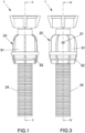
- valve assembly according to the invention, indicated as a whole with the reference number 1, comprises an enclosure or container body formed by a valve body 20 associated with a valve shell composed of an upper half-shell 91 and a lower half-shell 92.
- the axial chamber 21 is put in communication with the delivery mouth of a faucet to which the valve body 20 is fixed by means of a ring nut 14 with the interposition of a filter 12 and a gasket 13.
- the filter 12 is coupled to a respective support 18, acting as an upper valve guide.
- a corrugated sheath 24 is associated with the lower shell 92 of the valve body 20 and with a water inlet hose 27.
- the corrugated sheath 24 is hermetically fixed to the lower half-shell 92, through a process of injection of plastic material 50 ( Figures 4 and 6 ), advantageously polypropylene, with a suitable co-molding mold, by welding the two components so that they become a single piece.
- plastic material 50 advantageously polypropylene
- plastic material 50 fills the interstices 51 illustrated in Figure 2 , formed between the outer surface of the sheath 24 and the inner wall of the lower half-shell 92 of the valve body 20.
- the corrugated sheath 24 is made of 100% polypropylene, whereas the lower shell 92 is made of 70% polypropylene and 30% fiber.
- the water inlet hose 27 is put in communication with the axial chamber 21 of the valve body 20. Furthermore, between the outer surface of the hose 27 and the inner surface of the corrugated sheath 24 a gap or cavity 26 is formed, which is put in communication with the lower portion 22a of the annular chamber 22 through holes 28 for the passage of fluid, formed in the lower half-shell 92 of the valve body 20.
- annular magnet 2 housed in an annular support 10 and axially movable in opposition to a spring 6, due to the thrust of a membrane 3, which is arranged in the side of the annular chamber 22 in communication with the holes 28.
- the spring 6 is mounted coaxially with an inner shank 29 of the valve body 20.
- the inner shank 29 of the valve body 20 defines, internally, the axial chamber 21 and, externally, the annular chamber 22.
- the membrane 3 divides the annular chamber 22 into two separate compartments: the lower one 22a which is in communication with the gap 26 through holes 28 for the passage of fluid, and an upper one 22b equipped with a transparent window 31 through which the raised position of the support 10 of the magnet 2 can be seen.
- the plug 7 which slides axially and has a mushroom head 71 capable of closing the passage of fluid in the axial chamber 21, at a narrowing defined by an inclined surface 30 of the axial chamber 21 itself ( Figure 2 ).
- the mushroom head 71 defines an annular slot in which an O-ring 8 is housed.
- a cylindrical magnet 5 is housed in the body of the plug 7, the latter being slidingly arranged inside the chamber 52 of the valve guide 4.
- valve assembly 1 of the invention is equipped, at the upper portion 29a of the water inlet shank 29, with a filter 12 which is bayonet-coupled to an upper valve guide 18 ( Figure 7 ).
- the filter 12 has a filtering wall 53 from which feet 54a, 54b, 54c protrude in the axial direction, each of which has a respective seat 55a, 55b, 55c intended to form the slot 58 for housing the flat gasket 13.
- the upper valve guide 18, at its attachment to the filter 12 has feet 56a, 56b, 56c also having seats 57a, 57b, 57c.
- the feet 54a, 54b, 54c of the filter 12 are arranged between the corresponding feet 56a, 56b, 56c of the valve guide 18, forming together with these a continuous annular slot 58 which receives the flat gasket 13, which in turn assembles the filter 12 and the valve guide 18 together in the condition shown in Figure 9 .
- the filter 12, the valve guide 18 and the gasket 13 form a single body which can be inserted by interlocking in the upper part 29a of the shank 29 for the inlet of water into the valve assembly.
- the valve assembly of the invention further comprises, on the same part 29a of the shank 29, a non-return valve having a plug 41 which closes on the mouth 59 of the water inlet valve guide 18.
- a spring 43 is provided to push the plug 41 into the closing position of the mouth 59, also by means of an O-ring 42. This prevents water and air from leaking from the hose 27.
- the operation of the safety valve assembly 1 according to the present invention is as follows.
- This movement causes the plug 7 to slide through the valve guide 4 so that the O-ring 8, mounted on the plug 7, abuts on the inclined surface 30 and interrupts the water flow.
- the annular support 10 which is advantageously colored in an evident way, for example red, is located in front of the windows 31, formed on the valve body 20, so that it is obvious that the inner mechanism is activated and that the water flow is blocked.
- the mechanism when the mechanism intervenes, it blocks the water flow even while the water is still flowing, which was not possible in conventional devices.
- Intervention of the mechanism according to the present invention is repeatable and this allows the possibility of testing completely (100%) the valve assembly.
- the assembly system is also simpler than in conventional devices, as a result of which the automation is less complicated, entirely to the advantage of the production economy.
- the improved safety valve assembly according to the present invention offers a considerable improvement in terms of assembly of the components, thus reducing the overall dimensions.
- An important advantage is the system of fixing the corrugated polypropylene sheath to the valve shell, by injection of plastic material through co-molding.
- a further important advantage is the fixing system of the filter 12 which intersects with the upper valve guide 18 and engages by interlocking, forming a slot which becomes the seat housing the flat gasket 13, forming a single piece which is then inserted in the valve body under mechanical force.
- non-return valve consisting of the check valve 41 with O-ring 42 and spring 43, which allows the incoming fluid to pass freely while it blocks, by sealing on the inclined surface of the upper valve guide 18, the fluid inside the valve and consequently in the inlet hose.
Claims (7)
- Ensemble de soupape de sécurité pour tuyaux d'arrivée d'eau de machines à laver et de lave-vaisselle, du type comprenant un corps de soupape (20) formé d'une demi-coquille supérieure (91) et d'une demi-coquille inférieure (92), une tige intérieure (29) équipée d'une partie supérieure (29a) prévue au niveau d'un écrou à anneau (14) pour la fixation au robinet d'arrivée d'eau et d'un guide de soupape inférieur (4), dans lequel une chambre axiale (21) est formée entre le guide de soupape inférieur (4) et ladite tige (29) et dans lequel une chambre annulaire (22) est formée entre la tige (29) et lesdites demi-coquilles (91,92), une membrane (3) étant prévue pour diviser ladite chambre annulaire (22) en un compartiment supérieur (22b) et un compartiment inférieur (22a), un filtre (12) étant en outre disposé au niveau de ladite partie supérieure (29a) de la tige (29), couplé par verrouillage à un guide de soupape supérieur respectif (18), ledit filtre (12) étant pourvu d'une partie filtrante (53) et de pieds axiaux (54a, 54b, 54c), chacun pourvu d'un siège respectif (55a, 55b, 55c), caractérisé en ce que ledit guide de soupape supérieur (18), au niveau de sa fixation au filtre (12), a des pieds (56a, 56b, 56c) ayant également des sièges (57a, 57b, 57c), qui, à l'état couplé du guide de soupape supérieur (18) avec le filtre (12), forment, avec les sièges correspondants (55a, 55b, 55c) du filtre (12), une fente (58) pouvant recevoir un joint (13) dans la position de couplage du filtre (12) et du guide de soupape supérieur (18).
- Ensemble de soupape selon la revendication 1, caractérisé en ce qu'il comprend en outre un tuyau d'arrivée d'eau (27), à l'extérieur duquel est disposée une gaine (24), dans lequel une injection de matière plastique (50) est prévue à l'intérieur des interstices (51) formés entre la surface extérieure de ladite gaine (24) et la paroi intérieure de ladite demi-coquille inférieure (92), de manière à réaliser la fermeture hermétique entre cette dernière et la gaine (24) elle-même.
- Ensemble de soupape selon la revendication 1, caractérisé en ce qu'il prévoit un clapet anti-retour disposé sur ladite partie supérieure (29a) de la tige (29), dans lequel ledit clapet anti-retour comprend un bouchon (41) qui se ferme sur l'embouchure (59) du guide de soupape d'arrivée d'eau (18).
- Ensemble de soupape selon la revendication 3, caractérisé en ce que ledit clapet anti-retour comprend en outre un ressort (43) qui pousse le bouchon (41) à la position de fermeture de ladite embouchure (59).
- Ensemble de soupape selon la revendication 4, caractérisé en ce que ledit clapet anti-retour comprend en outre un joint torique (42) sur ledit bouchon (41).
- Ensemble de soupape selon les revendications 1, 2 ou 3, caractérisé en ce que ledit tuyau d'arrivée d'eau (27) définit un espace (26) avec ladite gaine (24) et est en communication avec ladite chambre axiale (21) dudit corps de soupape (20), ledit espace (26) étant en communication avec ladite chambre annulaire (22) au moyen d'orifices de passage de fluide (28) formés dans ladite coque inférieure (92), dans ladite chambre annulaire (22) se trouvant également un aimant annulaire (2) logé dans un support annulaire (10) et se déplaçant axialement en opposition à un ressort (6), sous l'effet de la poussée d'une membrane (3) disposée sur le côté de la chambre annulaire (22) en communication avec lesdits orifices (28), ledit ressort (6) étant monté coaxialement à une tige intérieure (29) dudit corps de soupape (20), ladite tige intérieure (29) dudit corps de soupape (20) définissant, intérieurement, ladite chambre axiale (21) et, extérieurement, ladite chambre annulaire (22), ladite membrane (3) divisant ladite chambre annulaire (22) en deux compartiments distincts, un compartiment inférieur (22a) en communication avec ledit espace (26) à travers lesdits orifices de passage de fluide (28), et un compartiment supérieur (22b) pourvu de fenêtres transparentes (31), dans ladite chambre axiale (21), à l'intérieur de ladite tige (29), se trouvant également un bouchon (7) qui coulisse axialement et possède une tête de champignon (71) pouvant fermer le passage du fluide dans ladite chambre axiale (21), au niveau d'un rétrécissement défini par une surface inclinée (30) de ladite chambre axiale (21), un aimant cylindrique (5) étant logé dans un siège cylindrique dudit bouchon qui coulisse dans un guide de soupape (4).
- Ensemble de soupape de sécurité, selon la revendication 6, caractérisé en ce que ladite gaine ondulée (24) est en polypropylène, ladite coque inférieure (92) étant en polypropylène et fibre.
Applications Claiming Priority (3)
| Application Number | Priority Date | Filing Date | Title |
|---|---|---|---|
| IT102021000012146A IT202100012146A1 (it) | 2021-05-12 | 2021-05-12 | Gruppo valvola di sicurezza perfezionato, per il tubo di carico dell’acqua di lavatrici e lavastoviglie |
| IT202200008966 | 2022-05-03 | ||
| PCT/IB2022/054375 WO2022238920A1 (fr) | 2021-05-12 | 2022-05-11 | Ensemble soupape de sécurité amélioré pour tuyaux d'entrée d'eau de machines à laver et de lave-vaisselle |
Publications (2)
| Publication Number | Publication Date |
|---|---|
| EP4312702A1 EP4312702A1 (fr) | 2024-02-07 |
| EP4312702B1 true EP4312702B1 (fr) | 2024-05-01 |
Family
ID=84028911
Family Applications (1)
| Application Number | Title | Priority Date | Filing Date |
|---|---|---|---|
| EP22724503.2A Active EP4312702B1 (fr) | 2021-05-12 | 2022-05-11 | Ensemble soupape de sécurité amélioré pour tuyaux d'entrée d'eau de machines à laver et de lave-vaisselle |
Country Status (2)
| Country | Link |
|---|---|
| EP (1) | EP4312702B1 (fr) |
| WO (1) | WO2022238920A1 (fr) |
Family Cites Families (6)
| Publication number | Priority date | Publication date | Assignee | Title |
|---|---|---|---|---|
| ITTO20050876A1 (it) * | 2005-12-15 | 2007-06-16 | Eltek Spa | Dispositivo di sicurezza antiallagamento per elettrodomestici, in particolare macchine di lavaggio |
| DE102009028587A1 (de) * | 2009-08-17 | 2011-02-24 | BSH Bosch und Siemens Hausgeräte GmbH | Wasserführendes Hausgerät |
| ITUB20153522A1 (it) * | 2015-09-10 | 2017-03-10 | Eltek Spa | Dispositivo idraulico di controllo e trattamento, particolarmente per apparati o impianti idraulici |
| IT201700026951A1 (it) * | 2017-03-10 | 2018-09-10 | Pavanello S A S Di Pavanello Giuseppe & C | Gruppo valvola di sicurezza, particolarmente per il tubo di carico dell'acqua di lavatrici e lavastoviglie. |
| IT201800004433A1 (it) * | 2018-04-12 | 2019-10-12 | Dispositivo antiallagamento di sicurezza per una macchina di lavaggio, del tipo che comprende magneti girevoli | |
| EP3821071B1 (fr) * | 2018-07-12 | 2022-09-07 | Seprio Plast ZN S.r.l. | Conduit anti-inondation muni d'une soupape de sécurité pour l'alimentation en eau |
-
2022
- 2022-05-11 EP EP22724503.2A patent/EP4312702B1/fr active Active
- 2022-05-11 WO PCT/IB2022/054375 patent/WO2022238920A1/fr active Application Filing
Also Published As
| Publication number | Publication date |
|---|---|
| WO2022238920A1 (fr) | 2022-11-17 |
| EP4312702A1 (fr) | 2024-02-07 |
Similar Documents
| Publication | Publication Date | Title |
|---|---|---|
| US3387816A (en) | Diverter spout | |
| EP4312702B1 (fr) | Ensemble soupape de sécurité amélioré pour tuyaux d'entrée d'eau de machines à laver et de lave-vaisselle | |
| US7673651B2 (en) | Flow regulating device | |
| CN210014049U (zh) | 一种分水阀芯 | |
| EP2812477B1 (fr) | Dispositif à électrovalve destiné à commander un écoulement de fluide, en particulier pour un appareil ménager tel qu'un lave-linge | |
| CA2291909C (fr) | Appareil pour ameliorer le siege d'une garniture de robinet | |
| EP2290152B1 (fr) | Dispositif de prévention de fuites pour conduites d'alimentation en eau d'appareils électriques domestiques | |
| WO2004094294A2 (fr) | Valve pour distributeur d'eau de refrigerateur | |
| EP0317021B1 (fr) | Clapet antiretour | |
| KR101869042B1 (ko) | 파우더 토출 용기 | |
| JP5252996B2 (ja) | 電磁式給水弁 | |
| CN110894883A (zh) | 一种水路切换阀 | |
| EP2809218B1 (fr) | Composant pour l'alimentation d'un liquide en pression dans une cuve d'une machine à laver au d'un lave-vaisselle | |
| EP2101123B1 (fr) | Unité de sectionneur d'eau, en particulier pour contrôler l'alimentation en eau dans un circuit d'eau d'une chaudière | |
| EP2466176B1 (fr) | Dispositif de commutation pour vanne d'eau | |
| US20190249795A1 (en) | Automatically resettable press-type switching valve and bathtub faucet | |
| KR20170003493U (ko) | 이중 밀폐구조 가스용기용 밸브 | |
| CN112081974B (zh) | 一种进水装置 | |
| CN213176983U (zh) | 用于净水机的电磁阀和净水机 | |
| KR200191668Y1 (ko) | 정전시 복귀방지 기능과 수동 개폐조작기능을 갖춘 전자밸브 | |
| AU2007200497A1 (en) | Faucet Valve | |
| US20180298888A1 (en) | Hydraulic machine and reversible metering pump equipped with such a machine | |
| RU2023128753A (ru) | Улучшенный предохранительный клапанный узел для впускных шлангов для воды стиральных машин и посудомоечных машин | |
| CN210397838U (zh) | 安全阀和热水器 | |
| IT202100012146A1 (it) | Gruppo valvola di sicurezza perfezionato, per il tubo di carico dell’acqua di lavatrici e lavastoviglie |
Legal Events
| Date | Code | Title | Description |
|---|---|---|---|
| STAA | Information on the status of an ep patent application or granted ep patent |
Free format text: STATUS: UNKNOWN |
|
| STAA | Information on the status of an ep patent application or granted ep patent |
Free format text: STATUS: THE INTERNATIONAL PUBLICATION HAS BEEN MADE |
|
| PUAI | Public reference made under article 153(3) epc to a published international application that has entered the european phase |
Free format text: ORIGINAL CODE: 0009012 |
|
| STAA | Information on the status of an ep patent application or granted ep patent |
Free format text: STATUS: REQUEST FOR EXAMINATION WAS MADE |
|
| 17P | Request for examination filed |
Effective date: 20231027 |
|
| AK | Designated contracting states |
Kind code of ref document: A1 Designated state(s): AL AT BE BG CH CY CZ DE DK EE ES FI FR GB GR HR HU IE IS IT LI LT LU LV MC MK MT NL NO PL PT RO RS SE SI SK SM TR |
|
| GRAP | Despatch of communication of intention to grant a patent |
Free format text: ORIGINAL CODE: EPIDOSNIGR1 |
|
| STAA | Information on the status of an ep patent application or granted ep patent |
Free format text: STATUS: GRANT OF PATENT IS INTENDED |
|
| GRAS | Grant fee paid |
Free format text: ORIGINAL CODE: EPIDOSNIGR3 |
|
| DAX | Request for extension of the european patent (deleted) | ||
| INTG | Intention to grant announced |
Effective date: 20240222 |
|
| RAP3 | Party data changed (applicant data changed or rights of an application transferred) |
Owner name: PAVANELLO S.R.L. |
|
| RAV | Requested validation state of the european patent: fee paid |
Extension state: MA Effective date: 20231027 |
|
| GRAA | (expected) grant |
Free format text: ORIGINAL CODE: 0009210 |
|
| STAA | Information on the status of an ep patent application or granted ep patent |
Free format text: STATUS: THE PATENT HAS BEEN GRANTED |
|
| AK | Designated contracting states |
Kind code of ref document: B1 Designated state(s): AL AT BE BG CH CY CZ DE DK EE ES FI FR GB GR HR HU IE IS IT LI LT LU LV MC MK MT NL NO PL PT RO RS SE SI SK SM TR |
|
| REG | Reference to a national code |
Ref country code: GB Ref legal event code: FG4D |