EP4312349A1 - Machine électrique - Google Patents
Machine électrique Download PDFInfo
- Publication number
- EP4312349A1 EP4312349A1 EP23185921.6A EP23185921A EP4312349A1 EP 4312349 A1 EP4312349 A1 EP 4312349A1 EP 23185921 A EP23185921 A EP 23185921A EP 4312349 A1 EP4312349 A1 EP 4312349A1
- Authority
- EP
- European Patent Office
- Prior art keywords
- openings
- laminated core
- coolant
- electric machine
- cover
- Prior art date
- Legal status (The legal status is an assumption and is not a legal conclusion. Google has not performed a legal analysis and makes no representation as to the accuracy of the status listed.)
- Pending
Links
Images

Classifications
-
- H—ELECTRICITY
- H02—GENERATION; CONVERSION OR DISTRIBUTION OF ELECTRIC POWER
- H02K—DYNAMO-ELECTRIC MACHINES
- H02K5/00—Casings; Enclosures; Supports
- H02K5/04—Casings or enclosures characterised by the shape, form or construction thereof
- H02K5/20—Casings or enclosures characterised by the shape, form or construction thereof with channels or ducts for flow of cooling medium
-
- H—ELECTRICITY
- H02—GENERATION; CONVERSION OR DISTRIBUTION OF ELECTRIC POWER
- H02K—DYNAMO-ELECTRIC MACHINES
- H02K1/00—Details of the magnetic circuit
- H02K1/06—Details of the magnetic circuit characterised by the shape, form or construction
- H02K1/22—Rotating parts of the magnetic circuit
- H02K1/32—Rotating parts of the magnetic circuit with channels or ducts for flow of cooling medium
-
- H—ELECTRICITY
- H02—GENERATION; CONVERSION OR DISTRIBUTION OF ELECTRIC POWER
- H02K—DYNAMO-ELECTRIC MACHINES
- H02K17/00—Asynchronous induction motors; Asynchronous induction generators
- H02K17/02—Asynchronous induction motors
- H02K17/16—Asynchronous induction motors having rotors with internally short-circuited windings, e.g. cage rotors
- H02K17/20—Asynchronous induction motors having rotors with internally short-circuited windings, e.g. cage rotors having deep-bar rotors
-
- H—ELECTRICITY
- H02—GENERATION; CONVERSION OR DISTRIBUTION OF ELECTRIC POWER
- H02K—DYNAMO-ELECTRIC MACHINES
- H02K5/00—Casings; Enclosures; Supports
- H02K5/04—Casings or enclosures characterised by the shape, form or construction thereof
- H02K5/20—Casings or enclosures characterised by the shape, form or construction thereof with channels or ducts for flow of cooling medium
- H02K5/203—Casings or enclosures characterised by the shape, form or construction thereof with channels or ducts for flow of cooling medium specially adapted for liquids, e.g. cooling jackets
-
- H—ELECTRICITY
- H02—GENERATION; CONVERSION OR DISTRIBUTION OF ELECTRIC POWER
- H02K—DYNAMO-ELECTRIC MACHINES
- H02K9/00—Arrangements for cooling or ventilating
-
- H—ELECTRICITY
- H02—GENERATION; CONVERSION OR DISTRIBUTION OF ELECTRIC POWER
- H02K—DYNAMO-ELECTRIC MACHINES
- H02K9/00—Arrangements for cooling or ventilating
- H02K9/19—Arrangements for cooling or ventilating for machines with closed casing and closed-circuit cooling using a liquid cooling medium, e.g. oil
-
- H—ELECTRICITY
- H02—GENERATION; CONVERSION OR DISTRIBUTION OF ELECTRIC POWER
- H02K—DYNAMO-ELECTRIC MACHINES
- H02K2213/00—Specific aspects, not otherwise provided for and not covered by codes H02K2201/00 - H02K2211/00
- H02K2213/03—Machines characterised by numerical values, ranges, mathematical expressions or similar information
Definitions
- the present invention relates to an electrical machine according to claim 1.
- the DE 10 2011 117 517 A1 In order to create a rotor of an electrical machine that is as robust and uniformly cooled as possible, proposes a device for flowing a coolant through the rotor, in which it is provided that cooling element lines are arranged in both press plates, which run from the rotor shaft in the direction of the conductor bars, and in which the aforementioned coolant lines in both press plates are either connected to a common coolant line which is arranged in the rotor shaft, or the aforementioned coolant lines in one press plate are connected to a first coolant line which is arranged in the rotor shaft, the coolant lines being in the other press plate are connected to a second coolant line which is arranged in the rotor shaft, wherein a coolant is supplied to the rotor via the coolant lines and is removed from the rotor via further coolant lines.
- the DE 10 2019 217 510 A1 relates to a rotor for an electric machine, having a rotor longitudinal axis, a rotor base body extending along the rotor longitudinal axis, at least one first balancing disk arranged in the axial direction next to a first base body side of the rotor base body, a coolant cavity being formed in the rotor base body for guiding coolant along the rotor longitudinal axis, wherein the coolant cavity has a coolant inlet for introducing the coolant into the coolant cavity and a coolant outlet for discharging the coolant from the coolant cavity.
- the first balancing disk has a coolant receptacle for receiving the coolant on a side facing away from the rotor base body, the first balancing disk having a first balancing disk cavity for passing the coolant through from the coolant receptacle to the Rotor base body, wherein a first inlet end of the first balancing disk cavity is fluidly coupled to the coolant receptacle, and wherein a first outlet end of the first balancing disk cavity is fluidly coupled to the coolant inlet of the coolant cavity.
- the coolant inlet is preferably at a smaller distance from the rotor's longitudinal axis than the coolant outlet, and the coolant inlet and/or the coolant outlet are opened or aligned in a direction parallel to the rotor's longitudinal axis. Coolant can be introduced into the coolant activity via the coolant inlet and can be led out of the coolant cavity via the coolant outlet.
- a rotor of an electric machine having a rotation axis, a disk pack extending around the rotation axis with a plurality of cooling channels, which extend axially through the disk pack with respect to the rotation axis and are spaced apart from one another in the circumferential direction of the rotor.
- the rotor has an attachment attached to each of the end faces of the disk pack, with an inlet region and an outlet region for each cooling channel being formed on the attachments, the outlet region of one of the attachments facing the cross section of the respective cooling channel in the axial direction facing away from the disk pack expanded radially outwards, the inlet area is either designed as a straight continuation of the cooling channel or expands radially inwards relative to the cooling channel of the respective cooling channel in the axial direction facing away from the disk pack and the attachments are each covered by a cover element.
- the cover element has an inlet opening for inflow into the inlet region and an outlet opening for outflow from the outlet region, the outlet opening assigned to one of the cooling channels being arranged radially further out than the inlet opening assigned to the same cooling channel.
- the WO 2020/023 363 A1 relates to an electrical machine with a rotor, which has a shaft extending in the axial direction and a rotor body surrounding the shaft, and a stator surrounding the rotor, wherein a coolant channel system is provided with a first channel structure, by means of which coolant from a through the shaft
- the shaft bore extending in the axial direction can be converted into a plurality of rotor recesses.
- an electrical machine comprising a laminated core with cooling channels and at least one cover lamella, the cover lamella having first openings for guiding coolant into cooling channels of the laminated core of the electrical machine and second openings for guiding coolant from cooling channels of the laminated core.
- the openings differ in terms of their radial position.
- the cover lamella is shaped in particular as a disk. Above all, it is a cover plate. Due to the different arrangement of first openings and second openings, these have different functions.
- the first openings are in particular feed openings, i.e. coolant flows through a first opening into a cooling channel of the laminated core, while the second openings are discharge openings, i.e. coolant flows through a second opening from a cooling channel of the laminated core.
- the coolant is in particular oil.
- the second openings are arranged radially further outwards than the first openings.
- the first and/or the second openings can have a shape, for example a circular shape or a shape of a semicircle.
- the first openings and the second openings can have the same shape.
- the openings are through openings, especially bores.
- the material used for the at least one cover lamella is not copper, but preferably a soft magnetic material, for example electrical sheet material.
- the cover lamella can have further, especially slot-shaped, openings, which, however, are arranged radially further out and do not serve to guide the coolant into or out of the laminated core or out of the laminated core.
- a center point and/or a center of gravity can be assigned to the openings.
- the respective center points and/or centroids of the second openings are located radially further out than the respective center points and/or centroids of the first openings. In a circular shape, the center and center of area coincide.
- the center points and/or centers of gravity of all first openings and all second openings lie in the radial direction between an inner and an outer radial distance of the cooling channels of the laminated core.
- the cooling channels in the laminated core extend in the axial direction, namely in the radial direction, starting from an internal distance to an external distance.
- the difference between the inner and outer distance corresponds to the diameter of the cooling channels.
- all cooling channels are arranged at the same radial height, in other words they have the same internal distance and external distance.
- the radial distance refers to a center line of the laminated core and/or a shaft of the electrical machine.
- the center points and/or centers of gravity of the second openings can be arranged in the radially outer half, preferably in the radially outer third, of the cooling channels.
- the center points and/or centers of gravity of the first openings can be arranged in the radial direction in the radially inner half, preferably in the radially inner third, of the cooling channels.
- the distance between the radially inner distance and the radially outer distance of the cooling channels can be divided into two halves or three thirds, with the radial position, as described above, being in the corresponding half or third.
- first openings and second openings alternate in the circumferential direction.
- the cover lamella does not have a first and a second opening at any point.
- the first openings and/or the second openings can be designed as semicircles. They therefore each have the shape of a semicircle. Each semicircle is characterized by an arc and a straight line, with the centers lying on the straight line.
- the semicircles of the first and second openings have a center point, wherein the center points of the first openings and the center points of the second openings can have the same radial distance from a center line of the cover lamella.
- the center of everyone Openings can therefore be located on an imaginary circle in the circumferential direction at the same radial height.
- the circular arcs of the first openings extend radially inwards, while the circular arcs of the second openings extend in particular radially outwards.
- the arrangement is different and serves to effect the different function of the openings.
- each cooling channel is assigned a first opening or a second opening.
- each cooling channel is assigned a first opening on one end face of the laminated core and a second opening on the other end face.
- the laminated core has at least one cover lamella on both end faces.
- the laminated core can have a plurality of cover lamellas on one end face, which are arranged in a stacked manner.
- a cover lamella rests on the front side of the laminated core, while further cover lamellas follow axially outwards in a stacked form.
- the cover slats can be designed identically.
- the cover slats can be arranged in such a way that the first openings and/or the second openings each at least partially overlap. In particular, the first openings completely overlap and/or the second openings completely overlap.
- straight, axial channels running in the stacked cover lamellas are created for introducing coolant into the laminated core and/or for discharging coolant from the laminated core.
- first openings of different stacked cover slats can only partially overlap.
- a channel for discharging and/or introducing coolant into the laminated core or out of the laminated core can thus be created, which does not run in a straight line in the axial direction, but rather branches off, for example.
- at least one channel, in particular all channels formed in the stacked cover slats can be at an angle to the straight axial direction.
- a meandering channel structure can be formed. The leadership of the The cooling medium can therefore be specifically influenced by stacking several cover fins.
- the cover lamellae of the laminated core can each have an outer diameter that deviates from the laminated core, whereby the outer diameter of the cover lamella can be a maximum of 75% of the outer diameter of the laminated core. Furthermore, the outside diameter of the cover lamella is preferably at most 50%, most preferably at most 30%, of the outside diameter of the laminated core.
- a cover lamella can in particular have a thickness between 0.1 mm and 4 mm, preferably between 0.2 mm and 0.5 mm, most preferably between 0.3 mm and 0.4 mm.
- the advantage of designing the cover lamella with a radially reduced diameter is that the at least one cover lamella can be subsequently arranged on the end face of the laminated core.
- the cover lamella can thus be subsequently arranged on an inner region of the laminated core after it has been inserted into the short-circuit ring that encases it.
- the electrical machine can further comprise at least one deflection element for redirecting coolant from the shaft towards the laminated core and/or for redirecting coolant from the laminated core towards the short-circuit ring and/or winding head of the electrical machine.
- the at least one deflection element for redirection is shaped, in particular, rotationally symmetrically.
- the deflection element can in particular be shaped as a stepped ring.
- the shaft may be hollow such that it includes an axial channel for conducting coolant. It also has radial shaft bores from which coolant emerges and must be diverted into at least one cooling channel in the laminated core.
- the deflection element can have webs. This creates several deflection areas.
- a shaft bore can be assigned to exactly one cooling channel by means of the deflection area, so that coolant in a shaft bore cannot be divided into several cooling channels.
- the inner radius of the deflection element can decrease continuously or in steps from an axial end which is arranged on the end face of the laminated core.
- the outer radius can be constant over the entire width.
- the inner radius of the deflection element can be selected such that the deflection element rests on the shaft in a first outer axial region, while the inner radius is larger in a second radial inner region facing the cover lamella, so that a deflection area for diverting coolant from the shaft bores in the shaft into cooling channels in the laminated core is formed.
- the deflection element is arranged such that the shaft bores open into the deflection area.
- the center points and/or center of gravity of the first openings are preferably located radially further inward than the outer radius of the deflection element, with the center points and/or center of gravity of the second openings lying radially further out than the outer radius of the deflection element.
- the inner deflection area is therefore not used to redirect coolant from the laminated core towards the short-circuit ring and/or winding head, but rather the end face and/or an outer surface of the deflection element.
- the cover slat blocks one path while opening the other path through the corresponding opening.
- the inner radius of the deflection element at the axially inner end is larger than the radially inner distance of the cooling channels in the laminated core, but smaller than the radially outer distance of the cooling channels.
- the electrical machine has two deflection elements which are arranged on the two cover lamellas on the end faces of the laminated core.
- the at least one deflection element is formed in particular as an additional component to the shaft and/or to the laminated core.
- the deflection element can be designed in one piece with the shaft, preferably as a shaft stop.
- the deflection element can thus be designed as a radially outwardly extending web of the shaft.
- a deflection element can be formed on one side as part of the shaft, so that the laminated core is formed during assembly of the electrical machine and the short-circuit ring can be applied to the shaft, with a deflection element being able to be used as a separate component on the other side.
- the deflection element is formed rotationally symmetrical, particularly simple production is possible and the assembly effort is significantly reduced.
- the deflection area is formed continuously in the circumferential direction.
- the geometry of the deflection element does not differentiate between first openings and second openings that it faces.
- the assembly effort is significantly reduced, since the assembly of a cover lamella is sufficient to enable the optimal supply of coolant to the cooling channels in the laminated core and the decoupling, for example in the direction of the short-circuit ring and/or winding head.
- inlet i.e. supply of coolant from the shaft into the laminated core
- outlet i.e. removal from the laminated core, for example to the short-circuit ring or the winding head
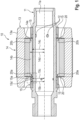
- an electrical machine 10 can be seen, which includes a shaft 11.
- a cooling channel 11a is arranged centrally in the shaft 11. Coolant 30 can emerge from the cooling channel 11a through radial shaft bores 12.
- the electrical machine 10 includes a Short-circuit ring 13, where in Figure 1 two cage bars 13a are shown.
- the electrical machine 10 includes a laminated core 14, which is applied to the shaft 11 and is radially encased by the short-circuit ring 13.
- a cover lamella 20 is arranged on both end faces of the laminated core 14.
- the laminated core 14 has cooling channels 14b, of which in Figure 2 two are shown, one above the shaft 11 and one below the shaft 11.
- the cooling channels 14b each have an inner radial distance 14c and an outer radial distance 14d, between which the cooling channels 14b extend in the axial direction.
- each cover lamella 20 is adjoined by a deflection element 15. This serves to release coolant 30 from the cooling channels 14b of the laminated core 14 radially and axially outwards or to direct coolant 30 from radial shaft bores 12 into the cooling channels 14b in the laminated core 14.
- the two in Figure 1 The cooling channels shown are each assigned a first opening 20a with respect to the left cover lamella, while at the other axial end (right) the channels are each assigned a second opening 20b of the cover lamella 20 arranged there.
- FIG 2 is the boxed area of Figure 1 presented in more detail.
- the area is shown in which the cover lamella 20 is arranged on the end face 14a of the laminated core 14 and the deflection element 15 is arranged on the cover lamella 20.
- the deflection element 15 has an outer radius 15b and an inner radius 15c.
- Two steps 15a are formed on the inside of the deflection elements 15.
- the inner radius 15c thus changes from the axially inner end of the deflection element 15 towards the axial outer end, with the inner radius in an axial end region being designed such that the inner wall of the deflection element 15 ends with the outer wall of the shaft 11.
- a circumferential deflection area 15d is thus formed into which the shaft bores 12 open.
- the outer radius 15b of the deflection element is constant, in particular over its entire axial width.
- the outer radius 15b is larger than the inner radial distance 14c and smaller than the outer radial distance 14d of the cooling channels 14b.
- the cover lamella 20 has first openings 20a and second openings 20b.
- Each cooling channel 14b in Figure 1 is a first opening 20a on one end and on the other Front side assigned a second opening 20b. It is the cooling channel that is in Figure 2 is shown, a first opening 20a is assigned, so that the discharge is blocked radially outwards.
- Coolant 30 is passed from at least one radial shaft bore 12 through the deflection area 15d into the cooling channel 14b.
- Figure 3 shows a section of a cover slat 20 Figure 1 in plan view, with the cover lamella 20 being designed accordingly along its entire circumference. It can be seen how first openings 20a and second openings 20b are formed, which alternate in the circumferential direction. All openings are designed as semicircles 21. The centers of gravity 20d of the second openings 20b are arranged radially further outward than the centers of gravity 20d of the first openings 20a. The center points 20c of the first openings 20a and those of the second openings 20b lie on the same imaginary circle with a constant radial radius. In other words, only the circular arcs of the semicircles extend either radially outward or radially inward.
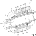
- FIG 4 shows a perspective view, whereby it can be clearly seen how the openings are assigned to the two cooling channels shown.
- the upper cooling channel 14b is in Figure 4 a first opening on the left and a second opening on the right.
- the lower cooling channel 14b is in Figure 4 There is also a first opening on the left and a second opening on the right.
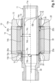
- FIG 5 shows the same view as Figure 1 , although the guidance of the coolant 30 is shown.
- the cooling channel 14b shown is assigned a first opening 20a of the corresponding cover lamella 20, while at the other axial end a second opening 20b is assigned to the cover lamella 20 arranged there.
Landscapes
- Engineering & Computer Science (AREA)
- Power Engineering (AREA)
- Iron Core Of Rotating Electric Machines (AREA)
- Motor Or Generator Cooling System (AREA)
Applications Claiming Priority (1)
| Application Number | Priority Date | Filing Date | Title |
|---|---|---|---|
| DE102022207625.7A DE102022207625A1 (de) | 2022-07-26 | 2022-07-26 | Elektrische Maschine |
Publications (1)
| Publication Number | Publication Date |
|---|---|
| EP4312349A1 true EP4312349A1 (fr) | 2024-01-31 |
Family
ID=87377933
Family Applications (1)
| Application Number | Title | Priority Date | Filing Date |
|---|---|---|---|
| EP23185921.6A Pending EP4312349A1 (fr) | 2022-07-26 | 2023-07-17 | Machine électrique |
Country Status (3)
| Country | Link |
|---|---|
| EP (1) | EP4312349A1 (fr) |
| CN (1) | CN117458773A (fr) |
| DE (1) | DE102022207625A1 (fr) |
Cited By (1)
| Publication number | Priority date | Publication date | Assignee | Title |
|---|---|---|---|---|
| WO2025235310A1 (fr) * | 2024-05-06 | 2025-11-13 | Atieva, Inc. | Moteur électrique à refroidissement liquide de bague d'extrémité |
Citations (10)
| Publication number | Priority date | Publication date | Assignee | Title |
|---|---|---|---|---|
| JPH04109844A (ja) * | 1990-08-29 | 1992-04-10 | Toshiba Corp | 誘導電動機 |
| JP2012161134A (ja) * | 2011-01-31 | 2012-08-23 | Toyota Motor Corp | 回転電機 |
| EP2062343B1 (fr) * | 2006-09-14 | 2012-08-29 | Siemens Aktiengesellschaft | Machine electrique avec rotor a refroidissement |
| DE102011117517A1 (de) | 2011-11-03 | 2013-05-08 | Iav Gmbh Ingenieurgesellschaft Auto Und Verkehr | Vorrichtung zur Kühlung einer elektrischen Maschine |
| US20190229571A1 (en) * | 2018-01-23 | 2019-07-25 | Honda Motor Co., Ltd. | Rotary electric machine and rotor thereof |
| WO2020023363A1 (fr) | 2018-07-27 | 2020-01-30 | Voconomy Inc. | Procédé et système d'interaction à distance sécurisée |
| DE102019206008A1 (de) | 2019-04-26 | 2020-10-29 | Robert Bosch Gmbh | Rotor einer elektrischen Maschine mit verbesserter Kühlleistung |
| DE102019217510A1 (de) | 2019-11-13 | 2021-05-20 | Volkswagen Aktiengesellschaft | Rotor, Elektromaschine und Kraftfahrzeug |
| DE102021108083A1 (de) * | 2020-03-31 | 2021-09-30 | Dana Belgium N.V. | Elektromotorkühlsystem und verfahren zum betreiben des systems |
| WO2022064627A1 (fr) * | 2020-09-25 | 2022-03-31 | 三菱電機株式会社 | Moteur électrique |
Family Cites Families (1)
| Publication number | Priority date | Publication date | Assignee | Title |
|---|---|---|---|---|
| JP2011254577A (ja) * | 2010-05-31 | 2011-12-15 | Aisin Seiki Co Ltd | 回転電機 |
-
2022
- 2022-07-26 DE DE102022207625.7A patent/DE102022207625A1/de active Pending
-
2023
- 2023-07-17 EP EP23185921.6A patent/EP4312349A1/fr active Pending
- 2023-07-20 CN CN202310896402.3A patent/CN117458773A/zh active Pending
Patent Citations (10)
| Publication number | Priority date | Publication date | Assignee | Title |
|---|---|---|---|---|
| JPH04109844A (ja) * | 1990-08-29 | 1992-04-10 | Toshiba Corp | 誘導電動機 |
| EP2062343B1 (fr) * | 2006-09-14 | 2012-08-29 | Siemens Aktiengesellschaft | Machine electrique avec rotor a refroidissement |
| JP2012161134A (ja) * | 2011-01-31 | 2012-08-23 | Toyota Motor Corp | 回転電機 |
| DE102011117517A1 (de) | 2011-11-03 | 2013-05-08 | Iav Gmbh Ingenieurgesellschaft Auto Und Verkehr | Vorrichtung zur Kühlung einer elektrischen Maschine |
| US20190229571A1 (en) * | 2018-01-23 | 2019-07-25 | Honda Motor Co., Ltd. | Rotary electric machine and rotor thereof |
| WO2020023363A1 (fr) | 2018-07-27 | 2020-01-30 | Voconomy Inc. | Procédé et système d'interaction à distance sécurisée |
| DE102019206008A1 (de) | 2019-04-26 | 2020-10-29 | Robert Bosch Gmbh | Rotor einer elektrischen Maschine mit verbesserter Kühlleistung |
| DE102019217510A1 (de) | 2019-11-13 | 2021-05-20 | Volkswagen Aktiengesellschaft | Rotor, Elektromaschine und Kraftfahrzeug |
| DE102021108083A1 (de) * | 2020-03-31 | 2021-09-30 | Dana Belgium N.V. | Elektromotorkühlsystem und verfahren zum betreiben des systems |
| WO2022064627A1 (fr) * | 2020-09-25 | 2022-03-31 | 三菱電機株式会社 | Moteur électrique |
Cited By (1)
| Publication number | Priority date | Publication date | Assignee | Title |
|---|---|---|---|---|
| WO2025235310A1 (fr) * | 2024-05-06 | 2025-11-13 | Atieva, Inc. | Moteur électrique à refroidissement liquide de bague d'extrémité |
Also Published As
| Publication number | Publication date |
|---|---|
| DE102022207625A1 (de) | 2024-02-01 |
| CN117458773A (zh) | 2024-01-26 |
Similar Documents
| Publication | Publication Date | Title |
|---|---|---|
| EP2744075B1 (fr) | Machine à rotation électrique | |
| EP2819799B1 (fr) | Mandrin de frettage avec refroidissement de l'outil | |
| EP3884565B1 (fr) | Machine électrique pourvue de plusieurs éléments d'enroulement rigides sous la forme de conducteurs creux | |
| EP2834906B1 (fr) | Moteur électrique | |
| EP0894358B1 (fr) | Enroulement de rotor pour machine electrique | |
| WO2021032240A1 (fr) | Stator et machine électrique tournante | |
| WO2005013459A1 (fr) | Machine electrique a refroidissement de rotor et procede de refroidissement correspondant | |
| DE102013020332A1 (de) | Elektrische Maschine, insbesondere Asynchronmaschine | |
| DE102014018223A1 (de) | Elektrische Maschine, insbesondere Asynchronmaschine | |
| EP3459157A1 (fr) | Machine électrique | |
| DE102021111700A1 (de) | Wickelkopfkühlung | |
| EP3739731A1 (fr) | Dispositif de guidage pour une tête d'enroulement d'une machine électrique fluide de refroidissement à flux et machine électrique | |
| WO1996005645A1 (fr) | Systeme comportant plusieurs barres conductrices s'etendant le long d'un axe longitudinal et empilees le long d'un axe vertical | |
| EP3544156B1 (fr) | Boîtier avec canaux de refroidissement pour une machine électrique | |
| EP4312349A1 (fr) | Machine électrique | |
| DE102015225589A1 (de) | Kühleinrichtung | |
| DE102019124256A1 (de) | Elektrische Maschine mit einer bestimmten Positionierung verschiedener Vertiefungen an einem nass laufenden Stator | |
| EP1283582B1 (fr) | Dispositif de refroidissement interne de conducteurs, particulièrement pour rotor de générateur | |
| DE102023125370A1 (de) | Elektrische Maschine mit Stator aufweisend eine direkte Mäanderkühlung und eine integrierte Düsenöffnung | |
| WO2024184096A1 (fr) | Machine électrique pour véhicule à moteur | |
| EP2693608A1 (fr) | Bobine pour une machine électrique | |
| DE102021212894A1 (de) | Elektrische Maschine, insbesondere elektrische Maschine für ein Kraftfahrzeug | |
| DE102023128372B4 (de) | Stator mit Kühlung der Wickelköpfe mittels einer Drallströmung und eine elektrische Maschine | |
| DE102022208566A1 (de) | Rotor einer Asynchronmaschine | |
| WO2025149111A1 (fr) | Stator à structure de canal de refroidissement s'étendant obliquement par rapport à une direction axiale; et machine électrique |
Legal Events
| Date | Code | Title | Description |
|---|---|---|---|
| PUAI | Public reference made under article 153(3) epc to a published international application that has entered the european phase |
Free format text: ORIGINAL CODE: 0009012 |
|
| STAA | Information on the status of an ep patent application or granted ep patent |
Free format text: STATUS: THE APPLICATION HAS BEEN PUBLISHED |
|
| AK | Designated contracting states |
Kind code of ref document: A1 Designated state(s): AL AT BE BG CH CY CZ DE DK EE ES FI FR GB GR HR HU IE IS IT LI LT LU LV MC ME MK MT NL NO PL PT RO RS SE SI SK SM TR |
|
| STAA | Information on the status of an ep patent application or granted ep patent |
Free format text: STATUS: REQUEST FOR EXAMINATION WAS MADE |
|
| 17P | Request for examination filed |
Effective date: 20240731 |
|
| RBV | Designated contracting states (corrected) |
Designated state(s): AL AT BE BG CH CY CZ DE DK EE ES FI FR GB GR HR HU IE IS IT LI LT LU LV MC ME MK MT NL NO PL PT RO RS SE SI SK SM TR |
|
| STAA | Information on the status of an ep patent application or granted ep patent |
Free format text: STATUS: EXAMINATION IS IN PROGRESS |
|
| 17Q | First examination report despatched |
Effective date: 20260323 |