EP4312186A1 - In-vehicle camera shield state determination device - Google Patents
In-vehicle camera shield state determination device Download PDFInfo
- Publication number
- EP4312186A1 EP4312186A1 EP23182839.3A EP23182839A EP4312186A1 EP 4312186 A1 EP4312186 A1 EP 4312186A1 EP 23182839 A EP23182839 A EP 23182839A EP 4312186 A1 EP4312186 A1 EP 4312186A1
- Authority
- EP
- European Patent Office
- Prior art keywords
- vehicle
- shield
- camera
- external camera
- determination unit
- Prior art date
- Legal status (The legal status is an assumption and is not a legal conclusion. Google has not performed a legal analysis and makes no representation as to the accuracy of the status listed.)
- Pending
Links
Images

Classifications
-
- H—ELECTRICITY
- H04—ELECTRIC COMMUNICATION TECHNIQUE
- H04N—PICTORIAL COMMUNICATION, e.g. TELEVISION
- H04N17/00—Diagnosis, testing or measuring for television systems or their details
- H04N17/002—Diagnosis, testing or measuring for television systems or their details for television cameras
-
- H—ELECTRICITY
- H04—ELECTRIC COMMUNICATION TECHNIQUE
- H04N—PICTORIAL COMMUNICATION, e.g. TELEVISION
- H04N23/00—Cameras or camera modules comprising electronic image sensors; Control thereof
- H04N23/50—Constructional details
- H04N23/55—Optical parts specially adapted for electronic image sensors; Mounting thereof
-
- G—PHYSICS
- G06—COMPUTING OR CALCULATING; COUNTING
- G06T—IMAGE DATA PROCESSING OR GENERATION, IN GENERAL
- G06T7/00—Image analysis
- G06T7/0002—Inspection of images, e.g. flaw detection
- G06T7/0004—Industrial image inspection
-
- G—PHYSICS
- G06—COMPUTING OR CALCULATING; COUNTING
- G06V—IMAGE OR VIDEO RECOGNITION OR UNDERSTANDING
- G06V10/00—Arrangements for image or video recognition or understanding
- G06V10/70—Arrangements for image or video recognition or understanding using pattern recognition or machine learning
- G06V10/74—Image or video pattern matching; Proximity measures in feature spaces
- G06V10/761—Proximity, similarity or dissimilarity measures
-
- G—PHYSICS
- G06—COMPUTING OR CALCULATING; COUNTING
- G06V—IMAGE OR VIDEO RECOGNITION OR UNDERSTANDING
- G06V20/00—Scenes; Scene-specific elements
- G06V20/50—Context or environment of the image
- G06V20/56—Context or environment of the image exterior to a vehicle by using sensors mounted on the vehicle
-
- G—PHYSICS
- G06—COMPUTING OR CALCULATING; COUNTING
- G06T—IMAGE DATA PROCESSING OR GENERATION, IN GENERAL
- G06T2207/00—Indexing scheme for image analysis or image enhancement
- G06T2207/10—Image acquisition modality
- G06T2207/10016—Video; Image sequence
-
- G—PHYSICS
- G06—COMPUTING OR CALCULATING; COUNTING
- G06T—IMAGE DATA PROCESSING OR GENERATION, IN GENERAL
- G06T2207/00—Indexing scheme for image analysis or image enhancement
- G06T2207/10—Image acquisition modality
- G06T2207/10028—Range image; Depth image; 3D point clouds
-
- G—PHYSICS
- G06—COMPUTING OR CALCULATING; COUNTING
- G06T—IMAGE DATA PROCESSING OR GENERATION, IN GENERAL
- G06T2207/00—Indexing scheme for image analysis or image enhancement
- G06T2207/30—Subject of image; Context of image processing
- G06T2207/30248—Vehicle exterior or interior
- G06T2207/30252—Vehicle exterior; Vicinity of vehicle
- G06T2207/30261—Obstacle
-
- G—PHYSICS
- G06—COMPUTING OR CALCULATING; COUNTING
- G06V—IMAGE OR VIDEO RECOGNITION OR UNDERSTANDING
- G06V2201/00—Indexing scheme relating to image or video recognition or understanding
- G06V2201/07—Target detection
Definitions
- the present disclosure relates to an in-vehicle camera shield state determination device.
- Japanese Unexamined Patent Publication No. 2015-232824 is known as a technical document relating to an in-vehicle camera shield state determination device.
- This publication discloses a device that detects a shielded area in which imaging by a camera is shielded due to a foreign matter adhering to a camera lens or the like, based on an image captured by the camera.
- the image of the camera becomes an image of the snow wall being uniform when the vehicle is near the snow wall.
- the image of the camera becomes an image of the snow wall being uniform when the vehicle is near the snow wall.
- an in-vehicle camera shield state determination device which determines a shield state of an external camera mounted on a vehicle, including: a shield detection unit configured to determine whether or not shield is detected by image processing of a captured image of the external camera, based on the captured image; a proximity determination unit configured to determine whether or not an object is close to the vehicle in an imaging direction of the external camera, based on a detection result of an external sensor of the vehicle; and a shield state determination unit configured to determine whether or not the external camera is in the shield state, based on a detection result of the shield detection unit and a determination result of the proximity determination unit, in which even if the shield detection unit detects shield by image processing of the captured image, when the proximity determination unit determines that the object is close to the vehicle in the imaging direction of the external camera, the shield state determination unit is configured not to determine that the external camera is in the shield state.
- the in-vehicle camera shield state determination device even if the shield detection unit detects the shield by the image processing of the captured image, when the proximity determination unit determines that the object is close to the vehicle in the imaging direction of the external camera, it is not determined that the external camera is in the shield state, so that it is possible to avoid erroneously determining that the external camera is in the shield state due to the object being close to the vehicle.
- the shield detection unit when the proximity determination unit determines that the object is close to the vehicle in the imaging direction of the external camera, the shield detection unit may be configured not to detect the shield by image processing on the captured image.
- a vehicle speed determination unit configured to determine whether or not a vehicle speed of the vehicle is less than a low speed determination threshold value, in which when the vehicle speed determination unit does not determine that the vehicle speed of the vehicle is less than the low speed determination threshold value, the shield state determination unit may be configured to determine whether or not the external camera is in the shield state, based on the detection result of the shield detection unit, regardless of determination by the proximity determination unit.
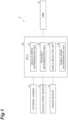
- An in-vehicle camera shield state determination device 1 illustrated in FIG. 1 is a device that determines whether or not an external camera 2 mounted on a vehicle such as a passenger car or a freight vehicle is in a shield state.
- the in-vehicle camera shield state determination device 1 includes an ECU 10, an external camera 2, a vehicle speed sensor 3, a radar sensor 4, and a human machine interface (HMI) 5.
- the in-vehicle camera shield state determination device 1 according to the present embodiment can also be applied to an autonomous driving vehicle.
- the shield state is a state in which the external camera 2 cannot appropriately image the area around the vehicle due to a foreign matter adhering to the lens of the external camera 2 or the like.
- the external camera 2 is installed inside a window glass of the vehicle, the external camera 2 is also in the shield state due to the adhesion of a foreign matter to the window glass.
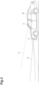
- FIG. 2 is a diagram illustrating an example of a situation in which the external camera 2 of a vehicle is not in a shield state.
- FIG. 2 illustrates a vehicle M, the external camera 2, an imaging range D (two-dot chain line) of the external camera 2, the radar sensor 4, and a detection range R of the radar sensor 4.
- the external camera 2 is not in the shield state.
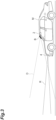
- FIG. 3 is a diagram illustrating an example of a situation in which the external camera of the vehicle is in a shield state.
- FIG. 3 shows a foreign matter B.
- the foreign matter B is not particularly limited.
- the foreign matter B can include various obstructions such as dirt, freezing snow, and even tree.
- the foreign matter B adheres to the windshield in front of the lens of the external camera 2, thereby blocking the imaging range D.
- the imaging range D shielded by the foreign matter B is indicated by a broken line.
- the external camera 2 is determined to be in the shield state.
- an in-vehicle camera shield state determination device 1 includes an electronic control unit (ECU) 10 for collectively managing the device.
- the ECU 10 is an electronic control unit having a Central Processing Unit (CPU) and a storage unit such as a Read Only Memory (ROM) or a Random Access Memory (RAM).
- CPU Central Processing Unit
- ROM Read Only Memory
- RAM Random Access Memory
- various functions are implemented by the CPU executing a program stored in the storage unit.
- the ECU 10 may be configured with a plurality of electronic units.
- the ECU 10 may be configured as a unit integrated with the external camera 2 or may be configured as a unit separate from the external camera 2.
- the ECU 10 is connected to the external camera 2, the vehicle speed sensor 3, the radar sensor 4, and the HMI 5.
- the external camera 2 is a camera for imaging the surroundings of the vehicle.
- the external camera 2 includes a front camera that images the front of the vehicle.
- the external cameras 2 used in the following description can all be read as the front camera.
- the front camera may be installed inside the windshield of the vehicle M, or may be a panoramic view camera.
- the panoramic view camera may be installed on the grill or bumper of the vehicle M.
- the external camera 2 may include a rear camera that images the rear of the vehicle or may include a side cameras (a left side camera and a right side camera) that images the side of the vehicle.
- the external camera 2 may be a camera having a distance measuring function such as a stereo camera.
- the external camera 2 may be a monocular camera capable of measuring a distance of an object in the captured image by performing a predetermined image process on the captured image.
- the vehicle speed sensor 3 is a detector that detects the vehicle speed of the vehicle M.
- a vehicle wheel speed sensor is used, which is provided on vehicle wheels of the vehicle M or on a drive shaft rotating integrally with vehicle wheels, and detects a rotational speed of the vehicle wheels.
- the vehicle speed sensor 3 transmits the detected vehicle speed information (vehicle wheel speed information) to the ECU 10.
- the radar sensor 4 is an external sensor for detecting an object outside the vehicle M.
- the radar sensor 4 includes, for example, a millimeter wave radar or a light detection and ranging (LIDAR).
- the radar sensor 4 detects an object around the vehicle M by using radio waves (for example, millimeter waves) or light, and also detects a distance between the vehicle M and the object. That is, the radar sensor 4 also functions as a distance measurement sensor that measures a distance between the vehicle M and an external object.
- the radar sensor 4 transmits information on the detected object (including position information and distance information of the object with respect to the vehicle M) to the ECU 10.
- the external sensor is not limited to the radar sensor 4.
- the external sensor may be a sonar sensor, and the external camera 2 capable of measuring a distance may be adopted.
- the HMI 5 is an interface that performs inputting and outputting of information between the in-vehicle camera shield state determination device 1 and the driver.
- the HMI 5 includes, for example, a display and a speaker.
- the HMI 5 outputs an image on the display and/or outputs a sound from the speaker according to a control signal from the ECU 10.
- the display may be a multi information display (MID) or a head up display (HUD).
- the HMI 5 may have an indicator lamp that lights or flicker during the shield state determination the external camera 2.
- the ECU 10 includes a vehicle speed determination unit 11, a proximity determination unit 12, a shield detection unit 13, and a shield state determination unit 14.
- the vehicle speed determination unit 11 determines whether or not the vehicle speed of the vehicle M is less than a low speed determination threshold value, based on the detection result of the vehicle speed sensor 3.
- the low speed determination threshold value is a threshold value of a preset value.
- the low speed determination threshold value is set to an appropriate value to prevent an erroneous determination of the shield state of the external camera 2 from being performed.
- the low speed determination threshold value may be set as a value at which it can be determined whether the vehicle M is stopped or traveling.
- the low speed determination threshold value may be set as 0.5 km/h, may be set as 1 km/h, may be set as 5 km/h, or may be set as 10 km/h.
- the value of the low speed determination threshold value is not particularly limited.
- the low speed determination threshold value may be used as the stop determination threshold value.
- the proximity determination unit 12 determines whether or not the object is close to the vehicle M in the imaging direction of the external camera 2, based on the detection result of the external sensor (for example, the radar sensor 4).
- the imaging direction of the external camera 2 is the front of the vehicle for a front camera, the rear of the vehicle for a rear camera, and the side of the vehicle for a side camera (the direction in which the camera is facing, among the vehicle left direction and the vehicle right direction).
- the imaging direction of the external camera 2 may be the optical axis direction of the camera lens.
- An object is assumed to be a snow wall, a wall of a structure, another vehicle approaching due to traffic congestion, or the like.
- the other vehicle is, for example, could be a large van body truck having a flat cargo bed rear surface.
- the proximity determination unit 12 may not perform the proximity determination in the case of an object smaller than a certain size.
- the proximity determination unit 12 may not perform proximity determination when the object is moving at a certain speed or more, or may not perform proximity determination when the relative speed between the object and the vehicle M is equal to or higher than a certain value.
- the proximity determination unit 12 may not perform the proximity determination.
- the proximity determination unit 12 measures a distance of the object in the imaging direction of the external camera 2, based on the detection result of the external sensor. For example, the proximity determination unit 12 determines whether or not the object is positioned in the imaging direction of the external camera 2 based on the position information on the object with respect to the vehicle M detected by the radar sensor 4, and recognizes (distance measurement) the distance between the object and the vehicle M, based on the distance information on the object detected by the radar sensor 4.
- an external camera 2 capable of measuring a distance may be used.
- the proximity determination unit 12 determines that the object is close to the vehicle M.
- the distance threshold value is a threshold value of a preset value.
- the distance threshold value is not particularly limited, but it could be any distance between 0 m and 2 m.
- the distance threshold value may be 0.5 m or 1 m.
- the proximity determination unit 12 performs the proximity determination for each imaging direction of each camera.
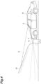
- FIG. 4 is a diagram illustrating an example of a situation in which the snow wall is close to the vehicle M.
- FIG. 4 shows a snow wall W.
- the proximity determination unit 12 recognizes the distance L between the snow wall W and the vehicle M, based on the detection result of the radar sensor 4. Since the distance L between the snow wall W and the vehicle M is less than the distance threshold value, the proximity determination unit 12 determines that the snow wall W is close to the vehicle M.
- the shield detection unit 13 determines whether or not shield is detected by image processing on the captured image of the external camera 2, based on the captured image of the external camera 2. For example, when a uniform image pattern without a feature amount spreads throughout the captured image, the shield detection unit 13 determines that the shield in the captured image of the external camera 2 is detected.
- the shield detection unit 13 may determine that the shield is detected when it is determined that the entire image is uniform, based on the brightness of the captured image, for example. Specifically, when the entire image has pixels of a predetermined percentage or more of the entire image in which the brightness of color component of each of R, G, and B is a certain threshold value or less, the shield detection unit 13 can determine that the shield is detected. The shield detection unit 13 may determine that shield is detected, when the entire image has pixels of a predetermined percentage or more of the entire image in which the fluctuation width of the brightness of color component of each of R, G, and B in a predetermined time is a certain threshold value or less.
- the image processing for shield detection is not particularly limited, and a well-known technique can be adopted. When there are a plurality of cameras as the external cameras 2, the shield detection unit 13 determines the detection of the shield for each captured image of each camera.
- the shield state determination unit 14 determines whether or not the external camera 2 is in the shield state, based on the determination result of the vehicle speed determination unit 11, the determination result of the proximity determination unit 12, and the detection result of the shield detection unit 13. When there are a plurality of cameras as the external cameras 2, the shield state determination unit 14 determines whether or not each of the cameras is in a shield state. In a case where the shield detection unit 13 does not determine that shield is detected by image processing on the captured image of the external camera 2, the shield state determination unit 14 does not determine that the external camera 2 is in the shield state.
- the vehicle speed determination unit 11 determines that the vehicle speed of the vehicle M is less than a low speed determination threshold value
- the proximity determination unit 12 determines that an object is close to the vehicle M in the imaging direction of the external camera 2
- the shield state determination unit 14 does not determine that the external camera 2 is in the shield state.
- the determination target of the proximity determination unit 12 and the detection target of the shield detection unit 13 are the same external camera 2.
- the vehicle speed determination unit 11 determines that the vehicle speed of the vehicle M is less than a low speed determination threshold value
- the proximity determination unit 12 does not determine that an object is close to the vehicle M in the imaging direction of the external camera 2
- the shield detection unit 13 detects shield by image processing on the captured image of the external camera 2
- the shield state determination unit 14 determines that the external camera 2 is in the shield state.
- the shield state determination unit 14 determines whether or not the external camera 2 is in the shield state, based on the detection result of the shield detection unit 13.
- the shield detection unit 13 determines that the shield is detected by image processing on the captured image of the external camera 2
- the shield state determination unit 14 determines that the external camera 2 is in the shield state.
- the shield detection unit 13 does not determine that shield is detected by image processing on the captured image of the external camera 2
- the shield state determination unit 14 does not determine that the external camera 2 is in the shield state.
- the shield state determination unit 14 When it is determined that the external camera 2 is in the shield state, the shield state determination unit 14 notifies the driver by HMI 5 that the external camera 2 is in the shield state.
- the shield state determination unit 14 notifies the driver that the external camera 2 is in the shield state by the image output of the display, the sound output of the speaker, or the lighting of the indicator lamp.
- FIG. 5 is a flowchart illustrating an example of a camera shield state determination process.
- the camera shield state determination process is executed, for example, when the engine of the vehicle M is in an ON state.
- the ECU 10 of the in-vehicle camera shield state determination device 1 determines whether or not the vehicle speed of the vehicle M is less than a low speed determination threshold value by the vehicle speed determination unit 11.
- the vehicle speed determination unit 11 makes a determination based on the detection result of the vehicle speed sensor 3.
- the ECU 10 proceeds to S11.
- the ECU 10 proceeds to S14.
- the ECU 10 measures the distance of the object in the imaging direction of the external camera 2 by the proximity determination unit 12. For example, the proximity determination unit 12 determines whether or not the object is positioned in the imaging direction of the external camera 2 based on the position information on the object with respect to the vehicle M detected by the radar sensor 4, and recognizes (distance measurement) the distance between the object and the vehicle M, based on the distance information on the object detected by the radar sensor 4.
- the ECU 10 determines whether or not the object is close to the vehicle M in the imaging direction of the external camera 2 by the proximity determination unit 12. For example, when the distance between the object and the vehicle M is less than the distance threshold value, the proximity determination unit 12 determines that the object is close to the vehicle M. When it is determined that the object is close to the vehicle M in the imaging direction of the external camera 2 (S12: YES), the ECU 10 proceeds to S13. When it is not determined that the object is close to the vehicle M in the imaging direction of the external camera 2 (S12: NO), the process proceeds to S14.
- the ECU 10 determines that the external camera 2 is not in the shield state by the shield state determination unit 14. After that, the ECU 10 ends the camera shield state determination process this time.
- the ECU 10 determines whether or not the shield detection unit 13 detects shield by image processing on the captured image of the external camera 2.
- the shield detection unit 13 determines that shield is detected, based on the captured image of the external camera 2, for example, when the entire image has pixels of a predetermined percentage or more of the entire image in which the brightness of color component of each of R, G, and B is a certain threshold value or less.
- the ECU 10 proceeds to S15.
- the ECU 10 proceeds to S13.
- the ECU 10 determines that the external camera 2 is in the shield state by the shield state determination unit 14.
- the shield state determination unit 14 notifies the driver by the HMI 5 that the external camera 2 is in the shield state. After that, the ECU 10 ends the camera shield state determination process this time.
- the shield detection unit 13 detects the shield by the image processing of the captured image, when the proximity determination unit 12 determines that the object is close to the vehicle M in the imaging direction of the external camera 2, it is not determined that the external camera 2 is in the shield state, so that it is possible to avoid erroneously determining that the external camera 2 is in the shield state due to the object being close to the vehicle M.
- the shield detection by image processing on the captured image of the external camera 2 is not performed, it is possible to avoid performing unnecessary image processing for shield detection, as compared with the case where the shield detection by image processing is always performed.
- the in-vehicle camera shield state determination device 1 when the vehicle speed determination unit 11 does not determine that the vehicle speed of the vehicle M is less than the low speed determination threshold value, regardless of the determination by the proximity determination unit 12, it is determined that the external camera 2 is in the shield state, based on the detection result of the shield detection unit 13, so that it is possible to avoid forcibly reducing the determination of the shield state, based on the determination of the proximity determination unit 12 until the vehicle M is traveling at a sufficient speed and the possibility of erroneous determination of the shield state due to the closeness of the object is low.
- the ECU 10 of the in-vehicle camera shield state determination device 1 does not necessarily need to include the vehicle speed determination unit 11.
- the ECU 10 may always make the determination by the proximity determination unit 12 without considering the vehicle speed of the vehicle M.
- the shield state determination unit 14 does not need to change the influence of the determination result of the proximity determination unit 12 on the final result of determination of the shield state according to the vehicle speed.
- the ECU 10 When the proximity determination unit 12 determines that an object is close to the vehicle M, the ECU 10 does not need to necessarily prohibit the detection of the shield by the shield detection unit 13. When the proximity determination unit 12 determines that an object is close to the vehicle M, the ECU 10 may detect the shield of the shield detection unit 13.
- the order of the proximity determination process in S12 in FIG. 5 and the shield detection process in S14 may be reversed.
- the ECU 10 may not perform the proximity determination processing.
Landscapes
- Engineering & Computer Science (AREA)
- Multimedia (AREA)
- Theoretical Computer Science (AREA)
- Computer Vision & Pattern Recognition (AREA)
- Physics & Mathematics (AREA)
- General Physics & Mathematics (AREA)
- Health & Medical Sciences (AREA)
- Signal Processing (AREA)
- General Health & Medical Sciences (AREA)
- Artificial Intelligence (AREA)
- Computing Systems (AREA)
- Databases & Information Systems (AREA)
- Evolutionary Computation (AREA)
- Medical Informatics (AREA)
- Software Systems (AREA)
- Quality & Reliability (AREA)
- Biomedical Technology (AREA)
- Studio Devices (AREA)
- Traffic Control Systems (AREA)
Abstract
Description
- This application is based upon and claims the benefit of priority from
Japanese Patent Application No. 2022-118665, filed on July 26, 2022 - The present disclosure relates to an in-vehicle camera shield state determination device.
- In the related art,
Japanese Unexamined Patent Publication No. 2015-232824 - However, in the above-described shield detection in the related art, the image of the camera becomes an image of the snow wall being uniform when the vehicle is near the snow wall. As a result, there is a risk of erroneously determining that the camera is in a shielded state due to the presence of adhering foreign matter.
- According to an aspect of the present disclosure, there is provided an in-vehicle camera shield state determination device which determines a shield state of an external camera mounted on a vehicle, including: a shield detection unit configured to determine whether or not shield is detected by image processing of a captured image of the external camera, based on the captured image; a proximity determination unit configured to determine whether or not an object is close to the vehicle in an imaging direction of the external camera, based on a detection result of an external sensor of the vehicle; and a shield state determination unit configured to determine whether or not the external camera is in the shield state, based on a detection result of the shield detection unit and a determination result of the proximity determination unit, in which even if the shield detection unit detects shield by image processing of the captured image, when the proximity determination unit determines that the object is close to the vehicle in the imaging direction of the external camera, the shield state determination unit is configured not to determine that the external camera is in the shield state.
- According to the in-vehicle camera shield state determination device according to an aspect of the present disclosure, even if the shield detection unit detects the shield by the image processing of the captured image, when the proximity determination unit determines that the object is close to the vehicle in the imaging direction of the external camera, it is not determined that the external camera is in the shield state, so that it is possible to avoid erroneously determining that the external camera is in the shield state due to the object being close to the vehicle.
- In the in-vehicle camera shield state determination device according to an aspect of the present disclosure, when the proximity determination unit determines that the object is close to the vehicle in the imaging direction of the external camera, the shield detection unit may be configured not to detect the shield by image processing on the captured image.
- In the in-vehicle camera shield state determination device according to an aspect of the present disclosure, a vehicle speed determination unit configured to determine whether or not a vehicle speed of the vehicle is less than a low speed determination threshold value, in which when the vehicle speed determination unit does not determine that the vehicle speed of the vehicle is less than the low speed determination threshold value, the shield state determination unit may be configured to determine whether or not the external camera is in the shield state, based on the detection result of the shield detection unit, regardless of determination by the proximity determination unit.
- According to the aspect of the present disclosure, it is possible to prevent an external camera from being erroneously determined to be in a shield state due to an object being close to a vehicle.
-
-
FIG. 1 is a block diagram illustrating an in-vehicle camera shield state determination device according to an embodiment. -
FIG. 2 is a diagram illustrating an example of a situation in which an external camera of a vehicle is not in a shield state. -
FIG. 3 is a diagram illustrating an example of a situation in which the external camera of the vehicle is in a shield state. -
FIG. 4 is a diagram illustrating an example of a situation in which the snow wall is close to the vehicle. -
FIG. 5 is a flowchart illustrating an example of a camera shield state determination process. - Hereinafter, the embodiment of the present disclosure will be described with reference to the drawings.
- An in-vehicle camera shield
state determination device 1 illustrated inFIG. 1 is a device that determines whether or not anexternal camera 2 mounted on a vehicle such as a passenger car or a freight vehicle is in a shield state. The in-vehicle camera shieldstate determination device 1 includes anECU 10, anexternal camera 2, a vehicle speed sensor 3, aradar sensor 4, and a human machine interface (HMI) 5. The in-vehicle camera shieldstate determination device 1 according to the present embodiment can also be applied to an autonomous driving vehicle. - The shield state is a state in which the
external camera 2 cannot appropriately image the area around the vehicle due to a foreign matter adhering to the lens of theexternal camera 2 or the like. When theexternal camera 2 is installed inside a window glass of the vehicle, theexternal camera 2 is also in the shield state due to the adhesion of a foreign matter to the window glass. -
FIG. 2 is a diagram illustrating an example of a situation in which theexternal camera 2 of a vehicle is not in a shield state.FIG. 2 illustrates a vehicle M, theexternal camera 2, an imaging range D (two-dot chain line) of theexternal camera 2, theradar sensor 4, and a detection range R of theradar sensor 4. In the situation illustrated inFIG. 2 , no foreign matter adheres to theexternal camera 2, and theexternal camera 2 is not in the shield state. -
FIG. 3 is a diagram illustrating an example of a situation in which the external camera of the vehicle is in a shield state.FIG. 3 shows a foreign matter B. The foreign matter B is not particularly limited. The foreign matter B can include various obstructions such as dirt, freezing snow, and even tree. The foreign matter B adheres to the windshield in front of the lens of theexternal camera 2, thereby blocking the imaging range D. InFIG. 3 , the imaging range D shielded by the foreign matter B is indicated by a broken line. In the situation shown inFIG. 3 , theexternal camera 2 is determined to be in the shield state. - As shown in
FIG. 1 , an in-vehicle camera shieldstate determination device 1 includes an electronic control unit (ECU) 10 for collectively managing the device. TheECU 10 is an electronic control unit having a Central Processing Unit (CPU) and a storage unit such as a Read Only Memory (ROM) or a Random Access Memory (RAM). In theECU 10, for example, various functions are implemented by the CPU executing a program stored in the storage unit. The ECU 10 may be configured with a plurality of electronic units. The ECU 10 may be configured as a unit integrated with theexternal camera 2 or may be configured as a unit separate from theexternal camera 2. - The ECU 10 is connected to the
external camera 2, the vehicle speed sensor 3, theradar sensor 4, and the HMI 5. Theexternal camera 2 is a camera for imaging the surroundings of the vehicle. Theexternal camera 2 includes a front camera that images the front of the vehicle. Theexternal cameras 2 used in the following description can all be read as the front camera. The front camera may be installed inside the windshield of the vehicle M, or may be a panoramic view camera. The panoramic view camera may be installed on the grill or bumper of the vehicle M. Theexternal camera 2 may include a rear camera that images the rear of the vehicle or may include a side cameras (a left side camera and a right side camera) that images the side of the vehicle. Theexternal camera 2 may be a camera having a distance measuring function such as a stereo camera. Theexternal camera 2 may be a monocular camera capable of measuring a distance of an object in the captured image by performing a predetermined image process on the captured image. - The vehicle speed sensor 3 is a detector that detects the vehicle speed of the vehicle M. As the vehicle speed sensor 3, for example, a vehicle wheel speed sensor is used, which is provided on vehicle wheels of the vehicle M or on a drive shaft rotating integrally with vehicle wheels, and detects a rotational speed of the vehicle wheels. The vehicle speed sensor 3 transmits the detected vehicle speed information (vehicle wheel speed information) to the
ECU 10. - The
radar sensor 4 is an external sensor for detecting an object outside the vehicle M. Theradar sensor 4 includes, for example, a millimeter wave radar or a light detection and ranging (LIDAR). Theradar sensor 4 detects an object around the vehicle M by using radio waves (for example, millimeter waves) or light, and also detects a distance between the vehicle M and the object. That is, theradar sensor 4 also functions as a distance measurement sensor that measures a distance between the vehicle M and an external object. Theradar sensor 4 transmits information on the detected object (including position information and distance information of the object with respect to the vehicle M) to theECU 10. - The external sensor (distance measurement sensor) is not limited to the
radar sensor 4. The external sensor (distance measurement sensor) may be a sonar sensor, and theexternal camera 2 capable of measuring a distance may be adopted. - The HMI 5 is an interface that performs inputting and outputting of information between the in-vehicle camera shield
state determination device 1 and the driver. The HMI 5 includes, for example, a display and a speaker. The HMI 5 outputs an image on the display and/or outputs a sound from the speaker according to a control signal from theECU 10. The display may be a multi information display (MID) or a head up display (HUD). The HMI 5 may have an indicator lamp that lights or flicker during the shield state determination theexternal camera 2. - Next, the functional configuration of the
ECU 10 will be described. TheECU 10 includes a vehiclespeed determination unit 11, aproximity determination unit 12, ashield detection unit 13, and a shieldstate determination unit 14. - The vehicle
speed determination unit 11 determines whether or not the vehicle speed of the vehicle M is less than a low speed determination threshold value, based on the detection result of the vehicle speed sensor 3. The low speed determination threshold value is a threshold value of a preset value. The low speed determination threshold value is set to an appropriate value to prevent an erroneous determination of the shield state of theexternal camera 2 from being performed. The low speed determination threshold value may be set as a value at which it can be determined whether the vehicle M is stopped or traveling. The low speed determination threshold value may be set as 0.5 km/h, may be set as 1 km/h, may be set as 5 km/h, or may be set as 10 km/h. The value of the low speed determination threshold value is not particularly limited. The low speed determination threshold value may be used as the stop determination threshold value. - The
proximity determination unit 12 determines whether or not the object is close to the vehicle M in the imaging direction of theexternal camera 2, based on the detection result of the external sensor (for example, the radar sensor 4). The imaging direction of theexternal camera 2 is the front of the vehicle for a front camera, the rear of the vehicle for a rear camera, and the side of the vehicle for a side camera (the direction in which the camera is facing, among the vehicle left direction and the vehicle right direction). The imaging direction of theexternal camera 2 may be the optical axis direction of the camera lens. - An object is assumed to be a snow wall, a wall of a structure, another vehicle approaching due to traffic congestion, or the like. The other vehicle is, for example, could be a large van body truck having a flat cargo bed rear surface. The
proximity determination unit 12 may not perform the proximity determination in the case of an object smaller than a certain size. Theproximity determination unit 12 may not perform proximity determination when the object is moving at a certain speed or more, or may not perform proximity determination when the relative speed between the object and the vehicle M is equal to or higher than a certain value. When the height of the object does not reach the attachment height of theexternal camera 2, theproximity determination unit 12 may not perform the proximity determination. - The
proximity determination unit 12 measures a distance of the object in the imaging direction of theexternal camera 2, based on the detection result of the external sensor. For example, theproximity determination unit 12 determines whether or not the object is positioned in the imaging direction of theexternal camera 2 based on the position information on the object with respect to the vehicle M detected by theradar sensor 4, and recognizes (distance measurement) the distance between the object and the vehicle M, based on the distance information on the object detected by theradar sensor 4. Instead of theradar sensor 4, anexternal camera 2 capable of measuring a distance may be used. - For example, when the distance between the object and the vehicle M is less than the distance threshold value, the
proximity determination unit 12 determines that the object is close to the vehicle M. The distance threshold value is a threshold value of a preset value. The distance threshold value is not particularly limited, but it could be any distance between 0 m and 2 m. The distance threshold value may be 0.5 m or 1 m. When a plurality of cameras are present as theexternal cameras 2, theproximity determination unit 12 performs the proximity determination for each imaging direction of each camera. -
FIG. 4 is a diagram illustrating an example of a situation in which the snow wall is close to the vehicle M.FIG. 4 shows a snow wall W. In the situation illustrated inFIG. 4 , theproximity determination unit 12 recognizes the distance L between the snow wall W and the vehicle M, based on the detection result of theradar sensor 4. Since the distance L between the snow wall W and the vehicle M is less than the distance threshold value, theproximity determination unit 12 determines that the snow wall W is close to the vehicle M. - The
shield detection unit 13 determines whether or not shield is detected by image processing on the captured image of theexternal camera 2, based on the captured image of theexternal camera 2. For example, when a uniform image pattern without a feature amount spreads throughout the captured image, theshield detection unit 13 determines that the shield in the captured image of theexternal camera 2 is detected. - The
shield detection unit 13 may determine that the shield is detected when it is determined that the entire image is uniform, based on the brightness of the captured image, for example. Specifically, when the entire image has pixels of a predetermined percentage or more of the entire image in which the brightness of color component of each of R, G, and B is a certain threshold value or less, theshield detection unit 13 can determine that the shield is detected. Theshield detection unit 13 may determine that shield is detected, when the entire image has pixels of a predetermined percentage or more of the entire image in which the fluctuation width of the brightness of color component of each of R, G, and B in a predetermined time is a certain threshold value or less. The image processing for shield detection is not particularly limited, and a well-known technique can be adopted. When there are a plurality of cameras as theexternal cameras 2, theshield detection unit 13 determines the detection of the shield for each captured image of each camera. - The shield
state determination unit 14 determines whether or not theexternal camera 2 is in the shield state, based on the determination result of the vehiclespeed determination unit 11, the determination result of theproximity determination unit 12, and the detection result of theshield detection unit 13. When there are a plurality of cameras as theexternal cameras 2, the shieldstate determination unit 14 determines whether or not each of the cameras is in a shield state. In a case where theshield detection unit 13 does not determine that shield is detected by image processing on the captured image of theexternal camera 2, the shieldstate determination unit 14 does not determine that theexternal camera 2 is in the shield state. - In a case where the vehicle
speed determination unit 11 determines that the vehicle speed of the vehicle M is less than a low speed determination threshold value, when theproximity determination unit 12 determines that an object is close to the vehicle M in the imaging direction of theexternal camera 2, even if theshield detection unit 13 detects shield by image processing on the captured image of theexternal camera 2, the shieldstate determination unit 14 does not determine that theexternal camera 2 is in the shield state. In this case, the determination target of theproximity determination unit 12 and the detection target of theshield detection unit 13 are the sameexternal camera 2. - On the other hand, in a case where the vehicle
speed determination unit 11 determines that the vehicle speed of the vehicle M is less than a low speed determination threshold value, when theproximity determination unit 12 does not determine that an object is close to the vehicle M in the imaging direction of theexternal camera 2, if theshield detection unit 13 detects shield by image processing on the captured image of theexternal camera 2, the shieldstate determination unit 14 determines that theexternal camera 2 is in the shield state. - When the vehicle
speed determination unit 11 determines that the vehicle speed of the vehicle M is less than the low speed determination threshold value, the shieldstate determination unit 14 does not perform the determination by theproximity determination unit 12. In this case, the shieldstate determination unit 14 determines whether or not theexternal camera 2 is in the shield state, based on the detection result of theshield detection unit 13. When theshield detection unit 13 determines that the shield is detected by image processing on the captured image of theexternal camera 2, the shieldstate determination unit 14 determines that theexternal camera 2 is in the shield state. When theshield detection unit 13 does not determine that shield is detected by image processing on the captured image of theexternal camera 2, the shieldstate determination unit 14 does not determine that theexternal camera 2 is in the shield state. - When it is determined that the
external camera 2 is in the shield state, the shieldstate determination unit 14 notifies the driver by HMI 5 that theexternal camera 2 is in the shield state. The shieldstate determination unit 14 notifies the driver that theexternal camera 2 is in the shield state by the image output of the display, the sound output of the speaker, or the lighting of the indicator lamp. - Subsequently, the processing by the in-vehicle camera shield
state determination device 1 according to the present embodiment will be described with reference toFIG. 5. FIG. 5 is a flowchart illustrating an example of a camera shield state determination process. The camera shield state determination process is executed, for example, when the engine of the vehicle M is in an ON state. - As illustrated in
FIG. 5 , in S10, theECU 10 of the in-vehicle camera shieldstate determination device 1 determines whether or not the vehicle speed of the vehicle M is less than a low speed determination threshold value by the vehiclespeed determination unit 11. The vehiclespeed determination unit 11 makes a determination based on the detection result of the vehicle speed sensor 3. When it is determined that the vehicle speed of the vehicle M is less than the low speed determination threshold value (S10: YES), theECU 10 proceeds to S11. When it is not determined that the vehicle speed of the vehicle M is less than the low speed determination threshold value (S10: NO), theECU 10 proceeds to S14. - In S11, the
ECU 10 measures the distance of the object in the imaging direction of theexternal camera 2 by theproximity determination unit 12. For example, theproximity determination unit 12 determines whether or not the object is positioned in the imaging direction of theexternal camera 2 based on the position information on the object with respect to the vehicle M detected by theradar sensor 4, and recognizes (distance measurement) the distance between the object and the vehicle M, based on the distance information on the object detected by theradar sensor 4. - In S12, the
ECU 10 determines whether or not the object is close to the vehicle M in the imaging direction of theexternal camera 2 by theproximity determination unit 12. For example, when the distance between the object and the vehicle M is less than the distance threshold value, theproximity determination unit 12 determines that the object is close to the vehicle M. When it is determined that the object is close to the vehicle M in the imaging direction of the external camera 2 (S12: YES), theECU 10 proceeds to S13. When it is not determined that the object is close to the vehicle M in the imaging direction of the external camera 2 (S12: NO), the process proceeds to S14. - In S13, the
ECU 10 determines that theexternal camera 2 is not in the shield state by the shieldstate determination unit 14. After that, theECU 10 ends the camera shield state determination process this time. - In S14, the
ECU 10 determines whether or not theshield detection unit 13 detects shield by image processing on the captured image of theexternal camera 2. Theshield detection unit 13 determines that shield is detected, based on the captured image of theexternal camera 2, for example, when the entire image has pixels of a predetermined percentage or more of the entire image in which the brightness of color component of each of R, G, and B is a certain threshold value or less. When it is determined that the shield is detected by image processing on the captured image (S14: YES), theECU 10 proceeds to S15. When it is not determined that the shield is detected by image processing on the captured image (S14: NO), theECU 10 proceeds to S13. - In S15, the
ECU 10 determines that theexternal camera 2 is in the shield state by the shieldstate determination unit 14. The shieldstate determination unit 14 notifies the driver by the HMI 5 that theexternal camera 2 is in the shield state. After that, theECU 10 ends the camera shield state determination process this time. - According to the in-vehicle camera shield
state determination device 1 according to the present embodiment described above, even if theshield detection unit 13 detects the shield by the image processing of the captured image, when theproximity determination unit 12 determines that the object is close to the vehicle M in the imaging direction of theexternal camera 2, it is not determined that theexternal camera 2 is in the shield state, so that it is possible to avoid erroneously determining that theexternal camera 2 is in the shield state due to the object being close to the vehicle M. - In addition, according to the in-vehicle camera shield
state determination device 1, when theproximity determination unit 12 determines that an object is close to the vehicle M in the imaging direction of theexternal camera 2, the shield detection by image processing on the captured image of theexternal camera 2 is not performed, it is possible to avoid performing unnecessary image processing for shield detection, as compared with the case where the shield detection by image processing is always performed. - Further, according to the in-vehicle camera shield
state determination device 1, when the vehiclespeed determination unit 11 does not determine that the vehicle speed of the vehicle M is less than the low speed determination threshold value, regardless of the determination by theproximity determination unit 12, it is determined that theexternal camera 2 is in the shield state, based on the detection result of theshield detection unit 13, so that it is possible to avoid forcibly reducing the determination of the shield state, based on the determination of theproximity determination unit 12 until the vehicle M is traveling at a sufficient speed and the possibility of erroneous determination of the shield state due to the closeness of the object is low. - Although the embodiment of the present disclosure has been described above, the present disclosure is not limited to the above-described embodiment. The present disclosure can be implemented in various forms including various modifications and improvements based on the knowledge of those skilled in the art, including the above-described embodiment.
- The
ECU 10 of the in-vehicle camera shieldstate determination device 1 does not necessarily need to include the vehiclespeed determination unit 11. TheECU 10 may always make the determination by theproximity determination unit 12 without considering the vehicle speed of the vehicle M. In this case, the shieldstate determination unit 14 does not need to change the influence of the determination result of theproximity determination unit 12 on the final result of determination of the shield state according to the vehicle speed. - When the
proximity determination unit 12 determines that an object is close to the vehicle M, theECU 10 does not need to necessarily prohibit the detection of the shield by theshield detection unit 13. When theproximity determination unit 12 determines that an object is close to the vehicle M, theECU 10 may detect the shield of theshield detection unit 13. - The order of the proximity determination process in S12 in
FIG. 5 and the shield detection process in S14 may be reversed. In this case, when the shield is not detected by image processing on the captured image of theexternal camera 2, in the shield detection processing performed earlier, theECU 10 may not perform the proximity determination processing.
Claims (3)
- An in-vehicle camera shield state determination device (1) which determines a shield state of an external camera (2) mounted on a vehicle, comprising:a shield detection unit (13) configured to determine whether or not shield is detected by image processing of a captured image of the external camera (2), based on the captured image;a proximity determination unit (12) configured to determine whether or not an object is close to the vehicle in an imaging direction of the external camera (2), based on a detection result of an external sensor of the vehicle; anda shield state determination unit (14) configured to determine whether or not the external camera (2) is in the shield state, based on a detection result of the shield detection unit (13) and a determination result of the proximity determination unit (12), whereineven if the shield detection unit (13) detects shield by image processing of the captured image, when the proximity determination unit (12) determines that the object is close to the vehicle in the imaging direction of the external camera (2), the shield state determination unit (14) is configured not to determine that the external camera (2) is in the shield state.
- The in-vehicle camera shield state determination device (1) according to claim 1, wherein
when the proximity determination unit (12) determines that the object is close to the vehicle in the imaging direction of the external camera (2), the shield detection unit (13) is configured not to detect the shield by image processing on the captured image. - The in-vehicle camera shield state determination device (1) according to claim 1 or 2, further comprising:a vehicle speed determination unit (11) configured to determine whether or not a vehicle speed of the vehicle is less than a low speed determination threshold value, whereinwhen the vehicle speed determination unit does not determine that the vehicle speed of the vehicle is less than the low speed determination threshold value, the shield state determination unit (14) is configured to determine whether or not the external camera (2) is in the shield state, based on the detection result of the shield detection unit (13), regardless of determination by the proximity determination unit (12).
Applications Claiming Priority (1)
| Application Number | Priority Date | Filing Date | Title |
|---|---|---|---|
| JP2022118665A JP2024016501A (en) | 2022-07-26 | 2022-07-26 | Vehicle-mounted camera shielding state determination device |
Publications (1)
| Publication Number | Publication Date |
|---|---|
| EP4312186A1 true EP4312186A1 (en) | 2024-01-31 |
Family
ID=87060495
Family Applications (1)
| Application Number | Title | Priority Date | Filing Date |
|---|---|---|---|
| EP23182839.3A Pending EP4312186A1 (en) | 2022-07-26 | 2023-06-30 | In-vehicle camera shield state determination device |
Country Status (4)
| Country | Link |
|---|---|
| US (1) | US12432435B2 (en) |
| EP (1) | EP4312186A1 (en) |
| JP (1) | JP2024016501A (en) |
| CN (1) | CN117459704A (en) |
Citations (3)
| Publication number | Priority date | Publication date | Assignee | Title |
|---|---|---|---|---|
| US20150177512A1 (en) * | 2012-07-27 | 2015-06-25 | Nissan Motor Co., Ltd. | Camera device, three-dimensional object detection device, and lens cleaning method |
| JP2015232824A (en) | 2014-06-10 | 2015-12-24 | 株式会社デンソー | Detection device |
| US10814873B2 (en) * | 2018-04-16 | 2020-10-27 | Toyota Jidosha Kabushiki Kaisha | Driving support apparatus |
Family Cites Families (19)
| Publication number | Priority date | Publication date | Assignee | Title |
|---|---|---|---|---|
| JP2001211449A (en) | 2000-01-27 | 2001-08-03 | Honda Motor Co Ltd | Vehicle image recognition device |
| JP2007038773A (en) | 2005-08-02 | 2007-02-15 | Auto Network Gijutsu Kenkyusho:Kk | In-vehicle camera inspection device |
| JP4654208B2 (en) * | 2007-02-13 | 2011-03-16 | 日立オートモティブシステムズ株式会社 | Vehicle environment recognition device |
| JP5680436B2 (en) | 2011-02-15 | 2015-03-04 | アルパイン株式会社 | Foreign matter adhesion determination device for in-vehicle camera lens |
| JP5633503B2 (en) * | 2011-11-29 | 2014-12-03 | 株式会社リコー | Image processing system, vehicle equipped with image processing system, image processing method and program |
| US9467687B2 (en) * | 2012-07-03 | 2016-10-11 | Clarion Co., Ltd. | Vehicle-mounted environment recognition device |
| CN104395156B (en) * | 2012-07-03 | 2017-02-22 | 歌乐株式会社 | Vehicle surrounding monitoring device |
| JP6380843B2 (en) * | 2013-12-19 | 2018-08-29 | 株式会社リコー | Object detection apparatus, mobile device control system including the same, and object detection program |
| JP6313198B2 (en) | 2014-11-28 | 2018-04-18 | 株式会社デンソー | Vehicle control device |
| JP6363517B2 (en) | 2015-01-21 | 2018-07-25 | 株式会社デンソー | Vehicle travel control device |
| JP6669059B2 (en) | 2016-12-27 | 2020-03-18 | トヨタ自動車株式会社 | Position calculation device |
| JP7111454B2 (en) | 2017-09-28 | 2022-08-02 | 株式会社デンソー | CONTROLLED VEHICLE SETTING DEVICE, CONTROLLED VEHICLE SETTING SYSTEM AND CONTROLLED VEHICLE SETTING METHOD |
| JP6805105B2 (en) | 2017-09-28 | 2020-12-23 | 株式会社デンソー | Control target vehicle setting device, control target vehicle setting system, and control target vehicle setting method |
| JP6996353B2 (en) | 2018-03-06 | 2022-01-17 | トヨタ自動車株式会社 | Object recognition device and vehicle travel control system |
| JP7063184B2 (en) | 2018-08-10 | 2022-05-09 | トヨタ自動車株式会社 | Object recognition device |
| JP2020092365A (en) | 2018-12-07 | 2020-06-11 | 三菱電機株式会社 | In-vehicle camera device and in-vehicle camera dirt detection method |
| JP7268497B2 (en) | 2019-06-24 | 2023-05-08 | トヨタ自動車株式会社 | signal recognition system |
| JP2021056882A (en) * | 2019-09-30 | 2021-04-08 | アイシン精機株式会社 | Periphery monitoring device and periphery monitoring program |
| JP2021181285A (en) | 2020-05-20 | 2021-11-25 | トヨタ自動車株式会社 | Vehicle sensor mounting structure and vehicle sensor bracket set |
-
2022
- 2022-07-26 JP JP2022118665A patent/JP2024016501A/en active Pending
-
2023
- 2023-06-30 EP EP23182839.3A patent/EP4312186A1/en active Pending
- 2023-07-17 CN CN202310877638.2A patent/CN117459704A/en active Pending
- 2023-07-19 US US18/354,852 patent/US12432435B2/en active Active
Patent Citations (3)
| Publication number | Priority date | Publication date | Assignee | Title |
|---|---|---|---|---|
| US20150177512A1 (en) * | 2012-07-27 | 2015-06-25 | Nissan Motor Co., Ltd. | Camera device, three-dimensional object detection device, and lens cleaning method |
| JP2015232824A (en) | 2014-06-10 | 2015-12-24 | 株式会社デンソー | Detection device |
| US10814873B2 (en) * | 2018-04-16 | 2020-10-27 | Toyota Jidosha Kabushiki Kaisha | Driving support apparatus |
Also Published As
| Publication number | Publication date |
|---|---|
| US20240040222A1 (en) | 2024-02-01 |
| US12432435B2 (en) | 2025-09-30 |
| CN117459704A (en) | 2024-01-26 |
| JP2024016501A (en) | 2024-02-07 |
Similar Documents
| Publication | Publication Date | Title |
|---|---|---|
| US20080007429A1 (en) | Visibility condition determining device for vehicle | |
| US10372131B2 (en) | Vehicles changing lanes based on trailing vehicles | |
| US9827956B2 (en) | Method and device for detecting a braking situation | |
| US9020747B2 (en) | Method for recognizing a turn-off maneuver | |
| CN109466555B (en) | Judging device and vehicle | |
| WO2017068701A1 (en) | Parking space detection method and device | |
| US11042996B2 (en) | Recognition apparatus | |
| JP5482670B2 (en) | Object detection device | |
| US20210099622A1 (en) | Imaging system and vehicle window used for the same | |
| CN112905139A (en) | Vehicle-mounted display screen control method and device, vehicle and storage medium | |
| EP4312186A1 (en) | In-vehicle camera shield state determination device | |
| US20250242827A1 (en) | In-vehicle display system and control method of in-vehicle display system | |
| US11100353B2 (en) | Apparatus of controlling region of interest of image and method for controlling the same | |
| JP2007293672A (en) | VEHICLE PHOTOGRAPHING APPARATUS AND METHOD FOR DETECTING DIRTY OF VEHICLE PHOTOGRAPHING APPARATUS | |
| JP2018136713A (en) | Driver visibility estimation device and vehicle control device | |
| CN118082692A (en) | Holographic image starting method, device, vehicle and storage medium | |
| US12159463B2 (en) | Target vehicle recognition apparatus and processing method of target vehicle recognition apparatus | |
| US11195029B2 (en) | Driver assistance system | |
| CN111845347B (en) | Tips for vehicle driving safety, vehicles and storage media | |
| JP2006107000A (en) | Method and device for deciding image abnormality | |
| US20250391178A1 (en) | Object recognition apparatus, object recognition method, and object recognition program | |
| JP7781039B2 (en) | Vehicle control device | |
| US20250136119A1 (en) | Vehicle and computer program | |
| US20240208523A1 (en) | Driving assistance device and driving assistance method | |
| JP7781038B2 (en) | Vehicle control device |
Legal Events
| Date | Code | Title | Description |
|---|---|---|---|
| PUAI | Public reference made under article 153(3) epc to a published international application that has entered the european phase |
Free format text: ORIGINAL CODE: 0009012 |
|
| STAA | Information on the status of an ep patent application or granted ep patent |
Free format text: STATUS: REQUEST FOR EXAMINATION WAS MADE |
|
| 17P | Request for examination filed |
Effective date: 20230630 |
|
| AK | Designated contracting states |
Kind code of ref document: A1 Designated state(s): AL AT BE BG CH CY CZ DE DK EE ES FI FR GB GR HR HU IE IS IT LI LT LU LV MC ME MK MT NL NO PL PT RO RS SE SI SK SM TR |
|
| GRAP | Despatch of communication of intention to grant a patent |
Free format text: ORIGINAL CODE: EPIDOSNIGR1 |
|
| STAA | Information on the status of an ep patent application or granted ep patent |
Free format text: STATUS: GRANT OF PATENT IS INTENDED |
|
| INTG | Intention to grant announced |
Effective date: 20260116 |
|
| GRAS | Grant fee paid |
Free format text: ORIGINAL CODE: EPIDOSNIGR3 |
|
| GRAA | (expected) grant |
Free format text: ORIGINAL CODE: 0009210 |
|
| STAA | Information on the status of an ep patent application or granted ep patent |
Free format text: STATUS: THE PATENT HAS BEEN GRANTED |