EP4312024A1 - Liquid chromatography column - Google Patents
Liquid chromatography column Download PDFInfo
- Publication number
- EP4312024A1 EP4312024A1 EP23188125.1A EP23188125A EP4312024A1 EP 4312024 A1 EP4312024 A1 EP 4312024A1 EP 23188125 A EP23188125 A EP 23188125A EP 4312024 A1 EP4312024 A1 EP 4312024A1
- Authority
- EP
- European Patent Office
- Prior art keywords
- column
- cap
- column tube
- liquid chromatography
- filter unit
- Prior art date
- Legal status (The legal status is an assumption and is not a legal conclusion. Google has not performed a legal analysis and makes no representation as to the accuracy of the status listed.)
- Granted
Links
Images





Classifications
-
- G—PHYSICS
- G01—MEASURING; TESTING
- G01N—INVESTIGATING OR ANALYSING MATERIALS BY DETERMINING THEIR CHEMICAL OR PHYSICAL PROPERTIES
- G01N30/00—Investigating or analysing materials by separation into components using adsorption, absorption or similar phenomena or using ion-exchange, e.g. chromatography or field flow fractionation
- G01N30/02—Column chromatography
- G01N30/60—Construction of the column
-
- B—PERFORMING OPERATIONS; TRANSPORTING
- B01—PHYSICAL OR CHEMICAL PROCESSES OR APPARATUS IN GENERAL
- B01D—SEPARATION
- B01D15/00—Separating processes involving the treatment of liquids with solid sorbents; Apparatus therefor
- B01D15/08—Selective adsorption, e.g. chromatography
- B01D15/10—Selective adsorption, e.g. chromatography characterised by constructional or operational features
- B01D15/22—Selective adsorption, e.g. chromatography characterised by constructional or operational features relating to the construction of the column
-
- G—PHYSICS
- G01—MEASURING; TESTING
- G01N—INVESTIGATING OR ANALYSING MATERIALS BY DETERMINING THEIR CHEMICAL OR PHYSICAL PROPERTIES
- G01N30/00—Investigating or analysing materials by separation into components using adsorption, absorption or similar phenomena or using ion-exchange, e.g. chromatography or field flow fractionation
- G01N30/02—Column chromatography
- G01N30/60—Construction of the column
- G01N30/6004—Construction of the column end pieces
- G01N30/603—Construction of the column end pieces retaining the stationary phase, e.g. Frits
-
- G—PHYSICS
- G01—MEASURING; TESTING
- G01N—INVESTIGATING OR ANALYSING MATERIALS BY DETERMINING THEIR CHEMICAL OR PHYSICAL PROPERTIES
- G01N30/00—Investigating or analysing materials by separation into components using adsorption, absorption or similar phenomena or using ion-exchange, e.g. chromatography or field flow fractionation
- G01N30/02—Column chromatography
- G01N30/60—Construction of the column
- G01N30/6004—Construction of the column end pieces
-
- G—PHYSICS
- G01—MEASURING; TESTING
- G01N—INVESTIGATING OR ANALYSING MATERIALS BY DETERMINING THEIR CHEMICAL OR PHYSICAL PROPERTIES
- G01N30/00—Investigating or analysing materials by separation into components using adsorption, absorption or similar phenomena or using ion-exchange, e.g. chromatography or field flow fractionation
- G01N30/02—Column chromatography
- G01N30/60—Construction of the column
- G01N30/6052—Construction of the column body
-
- G—PHYSICS
- G01—MEASURING; TESTING
- G01N—INVESTIGATING OR ANALYSING MATERIALS BY DETERMINING THEIR CHEMICAL OR PHYSICAL PROPERTIES
- G01N30/00—Investigating or analysing materials by separation into components using adsorption, absorption or similar phenomena or using ion-exchange, e.g. chromatography or field flow fractionation
- G01N30/02—Column chromatography
- G01N30/62—Detectors specially adapted therefor
- G01N30/74—Optical detectors
-
- G—PHYSICS
- G01—MEASURING; TESTING
- G01N—INVESTIGATING OR ANALYSING MATERIALS BY DETERMINING THEIR CHEMICAL OR PHYSICAL PROPERTIES
- G01N30/00—Investigating or analysing materials by separation into components using adsorption, absorption or similar phenomena or using ion-exchange, e.g. chromatography or field flow fractionation
- G01N30/02—Column chromatography
- G01N2030/022—Column chromatography characterised by the kind of separation mechanism
- G01N2030/027—Liquid chromatography
Definitions
- the present disclosure relates to a liquid chromatography column.
- a column disclosed in Japanese Patent Application Laid-Open ( JP-A) No. 2021-96137 has caps mounted by fastening to respective ends of a column tube.
- An exemplary embodiment of the present disclosure provides a liquid chromatography column capable of achieving close connection performance and capable of securing sufficient pressure endurance by simply tightening caps onto a column tube, without filler becoming entrapped between the caps and the end portions of the column tube.
- a liquid chromatography column of an embodiment of the present disclosure includes a column tube including a flow path that runs therethrough in an axial direction of the column tube and that is filled with a filler; a filter unit that is mounted at an axial direction end of the column tube to trap the filler inside the flow path; and a cap that includes a through hole communicated with the flow path through the filter unit and that is mounted at the column tube, wherein a gap, which is a space into which the filler overflowing from the flow path can escape when the cap is being attached to the column tube, is formed at an outer side of a contact surface at which the column tube and the filter unit contact each other.
- the liquid chromatography column of the present disclosure enables close connection performance to be realized and enables pressure endurance of a column to be secured by simply tightening a cap onto a column tube, without filler becoming entrapped between the cap and an end portion of the column tube.
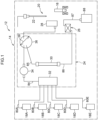
- the liquid chromatography device 12 is able to measure the concentration of glycohemoglobin (HbA1c) in whole blood automatically by a blood collection tube 16 is setting in a device body 14 of the liquid chromatography device 12.
- HbA1c glycohemoglobin
- the device body 14 of the liquid chromatography device 12 includes plural (five in the example illustrated in Fig. 1 ) eluent bottles 18A, 18B, 18C, 18D, 18E.
- Each of the eluent bottles 18A to 18E holds an eluent to be supplied to the liquid chromatography column 30, which is described later.
- These eluents may have, for example, different constituents, component ratios, pH, osmotic pressures, and the like according to application.
- the device body 14 further includes a sample preparation unit 20, an analysis unit 24, and a photometry unit 26.
- the blood collection tube 16 is held in the device body 14 so as to be able to move to a position enabling collection sample using a nozzle 22 of the sample preparation unit 20.
- the sample preparation unit 20 includes the nozzle 22 and a dilution chamber 28.
- the sample preparation unit 20 collects the blood sample from the blood collection tube 16 using the nozzle 22 and introduces the blood sample to the dilution chamber 28.
- the blood sample diluted in the dilution chamber 28 is introduced to the liquid chromatography column 30.
- the nozzle 22 is able to aspirate and eject liquids.
- the nozzle 22 is able to collect various liquids including blood samples in the blood collection tube 16 by aspiration, and is able to eject the various liquids.
- the analysis unit 24 includes the liquid chromatography column 30, a manifold 32, a liquid pump 34, and an injection valve 36.
- the analysis unit 24 controls adsorption and desorption of biogenic substance to and from a filler G (see Fig. 4B ) of the liquid chromatography column 30.
- the analysis unit 24 supplies various biogenic substances that have been separated in the liquid chromatography column 30 to the photometry unit 26.
- the setting temperature of the analysis unit 24 is, for example, 40°C.
- the manifold 32 is connected to each of the eluent bottles 18A to 18E through respective tubes 80A to 80E and is connected to the injection valve 36 through the liquid pump 34 via a tube 84.
- the manifold 32 selectively supplies an eluent from a designated eluent bottle from out of the plural eluent bottles 18A to 18E to the liquid chromatography column 30 by switching inbuilt valves of the manifold 32.
- the liquid pump 34 is provided partway along the tube 84 and imparts motive force to move the eluent to the injection valve 36.
- the injection valve 36 includes plural introduction ports and exhaust ports (omitted in the drawings) and is able to collect a given quantity of blood sample and introduce this blood sample to the liquid chromatography column 30.
- An injection loop 38 is connected to the injection valve 36.
- the injection loop 38 is able to hold a given quantity (for example several ⁇ L) of liquid.
- Appropriately switching the injection valve 36 enables selection of a state in which the injection loop 38 is in communication with the dilution chamber 28 and a blood sample is supplied from the dilution chamber 28 to the injection loop 38, or a state in which the injection loop 38 is in communication with the liquid chromatography column 30 via a tube 85, and a blood sample is introduced to the liquid chromatography column 30 from the injection loop 38.
- a six-way valve may, for example, be employed as such an injection valve 36.
- the photometry unit 26 is connected to a waste liquid chamber 88 via a tube 87, and liquid exhausted from the liquid chromatography column 30 is discharged therein.
- the photometry unit 26 performs optical detection of hemoglobin contained in liquid passing through the liquid chromatography column 30.
- sample fluid is a fluid that includes a blood sample or eluent, or both.
- the liquid chromatography column 30 includes a column tube 40, two filter units 50, and two caps 60.
- the two filter units 50 are a first filter unit 50A and a second filter unit 50B respectively provided at an upstream side and a downstream side of the column tube.
- the two caps 60 are a first cap 60A and a second cap 60B respectively provided at an upstream side and a downstream side of the column tube. Note that in the following description reference will be made to a filter unit 50 when not particularly discriminating between the first filter unit 50A and the second filter unit 50B, and reference will be made to a cap 60 when not particularly discriminating between the first cap 60A and the second cap 60B.
- the column tube 40 is formed in a substantially cylindrical tube shape extending in an axial direction (length direction) of a center axis L.
- a flow path 44 having a prescribed internal diameter is formed inside the column tube 40 along the center axis L of the column tube 40.
- the filler G which is described later, may be filled inside the flow path 44.
- the column tube 40 has a thickness in a radial direction (namely, in a direction orthogonal to the center axis L axial direction) of an amount that gives close contact with a retaining member 52 of the filter unit 50, as described later.
- the two axial direction ends of the center axis L of the column tube 40 namely the two end portions where the flow path 44 is open, are referred to as end faces 42. At least part of each of the end faces 42 is in close contact with the retaining member 52 of the filter unit 50.
- the portion of the end face 42 that is in close contact with the retaining member 52 is referred to as a contact surface C.
- the end face 42 and the contact surface C are both formed in ring shapes. In Fig. 2 , the contact surface C is a portion at a radial direction inside (flow path 44 side) of the end face 42.
- a column taper portion 42T that is a tapered face is formed to the end face 42 further to the radial direction outside (namely, on an outer peripheral face 42P side of the column tube) than the contact surface C that contacts the retaining member 52, which is described later.
- a boundary between the column taper portion 42T and the contact surface C is at the radial direction inside of the outer peripheral face of the filter unit 50 and is at the radial direction outside of an inner wall face of the flow path 44.
- the column taper portion 42T is inclined from this boundary toward the outside so as to separate from a bottom surface of the cap 60 as it nears the outer peripheral face 42P of the column tube 40. Namely, the column taper portion 42T faces the retaining member 52 of the filter unit 50, described later, but does not contact the retaining member 52.
- the shape and material of the column tube 40 may be set as appropriate.
- the column tube 40 is formed from a hard resin material.
- the first cap 60A and the second cap 60B are each formed in a bottomed circular cylinder shape including a side portion 64 and a bottom portion 62. As illustrated in Fig. 2 , the center axis L of the first cap 60A and the second cap 60B are coaxial with the center axis L of the column tube.
- the first cap 60A is a member that is mounted at a center axis L axial direction end of the column tube 40 so as to sandwich the first filter unit 50A, which is described later, between the bottom portion 62 of the first cap 60A and the center axis L axial direction end of the column tube 40.
- the second cap 60B is a member that is mounted at a center axis L axial direction other end portion of the column tube 40 so as to sandwich the second filter unit 50B, which is described later, between the bottom surface 62B of the second cap 60B and the center axis L axial direction other end portion of the column tube 40.
- the first cap 60A and the second cap 60B have equivalent structures and shapes to each other in the present exemplary embodiment as illustrated in Fig. 2
- the first cap 60A and the second cap 60B may have different structures from each other so as to be able to discriminate between upstream and downstream.
- the side portion 64 of the cap 60 has an internal diameter of an inside surface 64S that is substantially the same as the outer diameter of the outer peripheral face 42P of the column tube 40 (radial direction outside peripheral face) so as to be attachable to the column tube 40.
- a male thread is formed to the outer peripheral face 42P of the column tube 40
- a female thread is formed to the inside surface 64S of the cap 60, with the cap 60 attached by screwing onto the column tube 40.
- join portion 76 a portion where the column tube 40 and the cap 60 are joined in a state in which the cap 60 has been attached to the column tube 40.
- the side portion 64 of the cap 60 is mounted at the outer peripheral face 42P of the column tube 40 such that the filter unit 50, which is described later, is in close contact with the end portion of the circular cylinder-shaped column tube.
- the degree of close connection between the cap 60 and column tube 40, when the cap 60 is being mounted, can be adjusted by adjusting the degree of screwing by the join portion 76.
- a through hole 62C and a recess 62D are formed to the bottom portion 62 of the cap 60.
- the through hole 62C is a hole that pierces through the bottom portion 62 along the center axis L of the cap 60.
- the through hole 62C lets sample fluid, which is described later, pass through, is a path for the sample fluid to pass through to the flow path 44 via the filter unit 50, which is described later, and has a function to link to an external flow path where the sample fluid flows. Note that sometimes connection is made to the external flow path by a conventional screw fitting.
- the sample fluid is supplied through the through hole 62C of the first cap 60A and is exhausted from the through hole 62C of the second cap 60B.
- the through holes 62C extend along the direction of the center axis L of the column tube 40, and each have the same center axis L as that of the column tube 40.
- the liquid chromatography column 30 is accordingly formed in a substantially circular cylinder shape overall having a single center axis L.
- the recess 62D is a portion at the inner side of the bottom portion 62 indented in the center axis L axial direction so as to be separated from the column tube 40, and is a portion where the filter unit 50, which is described later, is fitted.
- the filter unit 50 can be retained more certainly by the cap due to the filter unit 50 being fitted to the indented recess 62D.
- the filter unit 50 includes, as an example illustrated in Fig. 2 , a porous body filter 54 and a retaining member 52 that retains the filter 54.
- the filter unit 50 is mounted at an end portion of the column tube 40.
- the filter 54 is held at a central portion of the retaining member 52.
- the first filter unit 50A and the second filter unit 50B in the present exemplary embodiment are formed with substantially the same shape as each other.
- the filter 54 is, for example, a membrane filter or a sintered filter that traps particles contained in the sample fluid.
- the filter 54 is formed in a short circular cylinder shape having a thickness along the center axis L axial direction.
- the diameter of the pores formed in the filter 54 is a size that allows the sample fluid to pass through but does not allow the filler G, which is described later, to pass through.
- the filter 54 is in communication with the through hole 62C, traps the filler G in the flow path 44 inside the flow path 44, and allows the sample fluid to pass through.
- the retaining member 52 is formed in a substantially circular ring shape having an outer diameter substantially the same as the internal diameter of the recess 62D, and is a member mounted in the recess 62D while holding the filter 54 at a central portion (inside a circular ring). Moreover, as illustrated in Fig. 3 , the retaining member 52 has a thickness in the radial direction of an amount that enables close contact with the end face 42 of the column tube 40 and has a height that is substantially the same as that of the filter 54 in the center axis L axial direction.
- the filter unit 50 is sandwiched between the end portion of the column tube 40 and the cap in a state in which the filter 54 is being retained by the retaining member 52.
- the center axis L axial direction thickness of the filter unit 50 is longer than a depth of the recess 62D (center axis L axial direction length), and in a state in which the filter unit 50 is mounted in the recess 62D as illustrated in Fig. 2 and Fig. 3 , the filter unit 50 protrudes out from the bottom surface 62B toward the column tube 40 side. The bottom surface 62B does not contact the column tube 40 in the example of Fig. 2 .
- the filter unit 50 and the column tube 40 are in close contact at the contact surface C in a state in which the cap 60 is attached to the column tube 40.
- sample fluid passing through the through hole 62C of the first cap 60A and supplied to the first filter unit 50A passes through a first filter 54A and is introduced to the flow path 44 of the column tube 40.
- the sample fluid passes from the flow path of the column tube 40 through a second filter 54B of the second filter unit 50B and is exhausted through the through hole 62C of the second cap 60B.
- the filter unit 50 and the column tube 40 are in close contact at the contact surface C by the cap 60 being tightened onto the column tube 40, and so neither filler nor sample fluid leaks from the contact surface C.
- the filler is trapped in the flow path 44 by the filter unit 50, but the sample fluid from the external flow path flows in sequence through the through hole 62C of the first cap 60A, the first filter 54A, the flow path 44 of the column, the second filter 54B, and the through hole 62C of the second cap 60B, and then outside.
- a gap 70 is positioned outside the contact surface C as a space surrounded by the column tube 40 and the retaining member 52, and the inside surface 64S of the cap 60.
- the gap 70 in the present exemplary embodiment is a ring-shaped space surrounded by the column taper portion 42T, the retaining member 52 of the filter unit 50, the bottom surface 62B of the cap 60, and the inside surface 64S of the cap 60. Operation of the gap 70 is described later.
- the retaining member 52 and the cap 60 may be formed by any material, and are, for example, formed from a hard resin material that is not readily deformed.
- the column tube 40, the retaining member 52 of the filter unit 50, and the cap 60 may all be formed from the same hard resin material.
- the filters 54 respectively retained by the first filter unit 50A and the second filter unit 50B described above may be formed as the same type of component or may be formed as separate types of components having different pore sizes, thicknesses, and the like. Namely, the filters 54 respectively retained by the first filter unit 50A and the second filter unit 50B may be appropriately decided according to application conditions of the sample and eluent in the liquid chromatography device 12.
- the first filter unit 50A and the second filter unit 50B may be formed as respective single bodies together with the first cap 60A or the second cap 60B or may be each be formed as separate bodies and then respectively joined thereto.
- the first filter unit 50A and the second filter unit 50B are able to be mounted at the column tube 40 at the same time as the first cap 60A and the second cap 60B, respectively.
- Fig. 4A and Fig. 4B the second cap 60B has already been attached to the column tube 40 at the opposite center axis L axial direction side to the illustrated end face 42 of the column tube 40, namely at the non-illustrated end face of the column tube 40.
- the filter unit 50 is fitted to the recess 62D of the cap 60.
- the filter unit 50 is sandwiched between the column tube 40 and the cap 60 by attaching the cap 60 to the column tube 40, with the filter unit 50 in close contact with the center axis L axial direction end face of the column tube 40.
- the filler G is introduced to the flow path 44 of the column tube 40, at an amount such that the filler G protrudes from the end face 42, before then attaching the other of the two caps 60 to the column tube 40.
- the filler G is a gel form substance for selective adsorption of hemoglobin variants in the sample and, for example, a methacrylic acid-methacrylic acid ester copolymer may be employed therefor.
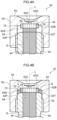
- Fig. 4A illustrates a state in which the cap 60 is being attached to the column tube 40.
- the filler G protrudes out further than the end face 42 under surface tension when the filler G overflows from the flow path 44 as illustrated in Fig. 4A .
- the filler G that overflows as the cap 60 is being attached is pressed by the filter unit 50, is fed toward the radial direction outside of the flow path 44 under pressure and enters the gap 70.
- Fig. 4B illustrates a state in which the filler G overflowed from the flow path 44 has entered the gap 70 due to the cap 60 being attached to the column tube 40.
- the filling of the filler G is completed when attachment of the cap 60 is complete.
- the filler G overflowing from the flow path 44 escapes into the gap 70 when the cap 60 is being attached to the column tube 40.
- the liquid chromatography column 30 having the flow path 44 completely filled with the filler G is assembled in such a procedure by the cap 60 being attached to the column tube 40 in the state in which the filler G has overflowed from the flow path 44 of the column tube 40.
- volume of the gap 70 may be set as appropriate.
- the blood sample is collected from the blood collection tube 16 and supplied to the dilution chamber 28 using the nozzle 22.
- a diluent is furthermore supplied to the dilution chamber 28 from a preparation fluid tank (omitted in the drawings), to prepare the sample fluid in the dilution chamber 28.
- the sample fluid prepared in the dilution chamber 28 is supplied to the injection loop 38 and held therein.
- the injection valve 36 is then switched, and the sample fluid held in the injection loop 38 is introduced to the liquid chromatography column 30.
- sA1c, HbA0, modified Hb, and the like are adsorbed to the filler G.
- the injection valve 36 is then appropriately switched again and eluents are supplied to the liquid chromatography column 30 in a predetermined control sequence.
- the sample fluid containing various separated hemoglobin is exhausted from the liquid chromatography column 30.
- the sample fluid is supplied to a photometry cell of the photometry unit 26 through a tube 86, and then guided to the waste liquid chamber 88 through the tube 87.
- the photometry unit 26 light is continuously irradiated onto the sample fluid from a light source, and after transmitted light has been split by a beam splitter, is received by a light receiving element.
- a chromatogram is computed and acquired by a control section of the photometry unit 26 based on photoreception results of the light receiving element.
- the column tube 40 and the retaining member 52 are in close contact at the contact surface C in the liquid chromatography column 30 according to the present exemplary embodiment. Screwing the cap 60 on when attaching to the column tube 40 enables close connection performance to be secured at the contact surface C, and enables the sample fluid or the like that is in the flow path 44 inside the liquid chromatography column 30 to be prevented from leaking out from the contact surface C.
- the gap 70 is formed by the cap 60, the column tube 40, and the retaining member 52 at the radial direction outside with respect to the contact surface C in a state in which the cap 60 is attached to the column tube 40.
- the filler G that has overflowed from the flow path 44 of the column tube 40 accordingly does not become entrapped at the contact surface C between the retaining member 52 and the end face 42 when the cap 60 is being attached, and instead escapes into the gap 70. This thereby enables close connection performance and pressure endurance of the column to be secured at the contact surface C simply by tightening the cap 60.
- the filter unit 50 of the liquid chromatography column 30 protrudes out toward the column tube 40 from the bottom surface 62B at the inner side of the cap 60, and so the filler G is readily pressed out and escapes easily from the contact surface C when the cap 60 is being attached.
- the end face of the filter 54 and the end face of the retaining member 52 are flush with each other in the radial direction.
- contact between the filler G and the filter 54 that is further toward the center than the retaining member 52 occurs before contact between the retaining member 52 and the end face of the flow path 44.
- the filler G is even more readily pressed from the center side to the gap 70 present at the outside.
- the cap 60 is attached to the outer peripheral face of the column tube 40 by screwing on the cap 60, other than screwing on, another mounting method such as fitting may be applied as appropriate.
- the column taper portion 42T which is an outwardly inclined tapered face, is formed to the column tube 40 of the liquid chromatography column 30 according to the present exemplary embodiment.
- the column taper portion 42T is inclined so as to separate from the end face of the retaining member 52 in the center axis L axial direction on approach to the inside surface 64S of the cap 60. Namely, the filler G that has overflowed from the flow path 44 of the column tube 40 is readily guided to the gap 70 by the column taper portion 42T. This accordingly enables the filler G that has overflowed from the flow path 44 of the column tube 40 to be guided toward the gap 70 when the cap 60 is being attached to the column tube 40.
- the column taper portion 42T of the column tube 40 of the liquid chromatography column 30 may be inclined at an angle exceeding 0° and less than or equal to 30° with respect to the contact surface C. Examples thereof include, for example, 5°, 10°, 15°, 20°, 25°, 30°.
- the contact surface C and the column taper portion 42T are formed to the end face 42 at the end portion of the column tube 40.
- Fig. 5 is a diagram illustrating a first modified example of the liquid chromatography column 30 according to the first exemplary embodiment.
- a column step portion 42S is formed to the end portion of the column tube 40 instead of the column taper portion 42T, with the column step portion 42S being formed in a shape stepped toward the opposite side in the center axis L axial direction to the filter unit 50.
- the column step portion 42S may be thought of as being a portion of smaller outer diameter at the center axis L axial direction end of the column tube 40. Note that other configuration and shapes are similar to those of the first exemplary embodiment.
- the gap 70 of the first modified example is provided at the outer side of the contact surface C as a space surrounded by the column tube 40 and the filter unit 50, and the inside surface 64S of the cap 60.
- the gap 70 of the present modified example is a space surrounded by the column step portion 42S, the filter unit 50, the bottom surface 62B of the cap 60, and the inside surface 64S of the cap 60.
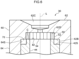
- Fig. 6 is a diagram illustrating a second modified example of the liquid chromatography column 30 according to the first exemplary embodiment.
- a bottom portion 62B of the cap 60 is at the same position in the center axis L axial direction as the contact surface C of the filter unit 50.
- a column step portion 42S is formed to an end portion of the column tube 40 similarly to in the first modified example.
- An outer diameter of the retaining member 52 in the filter unit 50 is formed larger than the outer diameter of the end face of the column tube 40. Namely, at the contacting faces of the retaining member 52 and the end face of the column tube 40, the face of the retaining member 52 where the column step portion 42S is not formed is formed larger than the face at the end face of the column tube 40.
- the larger formed face of the retaining member 52 is formed on the side where the column step portion 42S is not formed, and so this is thought to facilitate the filler being guided to the gap 70 by the column step portion 42S. Note that other configuration and shapes are similar to those of the first exemplary embodiment.
- the gap 70 of the second modified example is positioned at the outer side of the contact surface C, and is space surrounded by the column tube 40 and the inside surface 64S of the cap 60.
- the gap 70 in the present modified example is a space surrounded by the column step portion 42S, the bottom portion 62B of the cap 60, and the inside surface 64S of the cap 60.
- Fig. 7 is a diagram illustrating a third modified example of the liquid chromatography column 30 according to the first exemplary embodiment.
- the third modified example as illustrated in Fig. 7 is not formed with a column taper portion 42T at the end portion of the column tube 40. Note that the other configuration and shapes are similar to those of the first exemplary embodiment.
- the gap 70 of the third modified example is positioned outside the contact surface C as a space surrounded by the filter unit 50 and the inside surface 64S of the cap 60.
- the gap 70 of the present modified example is a space surrounded by the column tube 40, the filter unit 50, the bottom portion 62B of the cap 60, and the inside surface 64S of the cap 60.
- Fig. 8 is a diagram illustrating a fourth modified example of the liquid chromatography column 30 according to the first exemplary embodiment.
- a filter tapered portion 52T that is inclined toward the outside similarly to the column taper portion 42T is formed at a face of the filter unit 50 contacting the column tube 40.
- the column taper portion 42T is formed at the end portion of the column tube 40 at the end portion of the column tube 40 at the radial direction inside thereof, and the column step portion 42S is formed at the radial direction outside thereof. Note that other configuration and shapes are similar to those of the first exemplary embodiment.
- An angle formed between the filter tapered portion 52T and the contact surface C in the fourth modified example may, similarly to the column taper portion 42T, be an angle exceeding 0° and less than or equal to 30°.
- the gap 70 of the fourth modified example is positioned at the outer side of the contact surface C as a space surrounded by the column tube 40 and the filter unit 50, and the inside surface 64S of the cap 60.
- the gap 70 of the present modified example is a space surrounded by the column taper portion 42T, the column step portion 42S, the filter tapered portion 52T, the bottom portion 62B of the cap 60, and the inside surface 64S of the cap 60.
- the filler G overflowing from the flow path 44 can be moved even more readily into the gap 70 compared to in the liquid chromatography column 30 according to the first exemplary embodiment.
- the surface area of the contact surface C between the column tube 40 and the filter unit 50 can be enlarged compared to cases in which the filter tapered portion 52T is inclined at an angle greater than 30° with respect to the contact surface C. This enables a possibility of the filler G filled in the flow path 44 leaking from the flow path 44 to be reduced when the liquid chromatography column 30 is in use.
- Fig. 9 is a diagram illustrating a fifth modified example of the liquid chromatography column 30 according to the first exemplary embodiment.
- the column taper portion 42T is formed at the radial direction inside the end portion of the column tube 40 similarly to in the fourth modified example, and the column step portion 42S is formed at the radial direction outside thereof.
- the bottom portion 62B of the cap 60 is at the same position in the center axis L axial direction as the contact surface C of the filter unit 50 similarly to the second modified example. Note that other configuration and shapes are similar to those of the first exemplary embodiment.
- the gap 70 in the fifth modified example is positioned at the outer side of the contact surface C as a space surrounded by the column tube 40 and the inside surface 64S of the cap 60.
- the gap 70 of the present modified example is a space surrounded by the column taper portion 42T, the column step portion 42S, the bottom portion 62B of the cap 60, and the inside surface 64S of the cap 60.
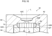
- Fig. 10 is a diagram illustrating a sixth modified example of the liquid chromatography column 30 according to the first exemplary embodiment.
- a filter tapered portion 52T similar to that of the fourth modified example is formed to the filter unit 50.
- the column tube 40 is not formed with a column taper portion 42T at the end portion of the column tube 40 similarly to in the third modified example. Note that other configuration and shapes are similar to those of the first exemplary embodiment.
- the gap 70 of the sixth modified example is positioned at the outer side of the contact surface C as a space surrounded by the filter unit 50 and the inside surface 64S of the cap 60.
- the gap 70 of the present modified example is a space surrounded by the column tube 40, the filter tapered portion 52T, the bottom portion 62B of the cap 60, and the inside surface 64S of the cap 60.
- liquid chromatography columns each include two caps, i.e., the first cap and the second cap, shaped so as to be symmetrical in the center axis L axial direction, there is no limitation thereto.
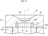
- Fig. 11 is a diagram illustrating a second exemplary embodiment of the liquid chromatography column 30 according to the present disclosure.
- the bottom portion 62B of the cap 60 and the end face 42 of the column tube 40 contact each other.
- the gap 70 that is in communication with the outer side of the cap 60 is formed at the same center axis L axial direction position as the contact surface C.
- the gap 70 is, as an example, a hole in the radial direction of the contact surface C opening toward the outside from the inside surface 64S of the cap 60. Note that the gap 70 is, as an example, formed at plural locations (two in Fig. 11 ) around the circumferential direction.
- the gaps 70 are spaces that enables the filler G to be exhausted from the contact surface C when the cap 60 is being attached.
- the gaps 70 of liquid chromatography column 30 may be closed off by seal members or the like after the cap 60 has been attached to prevent the filler G inside the gaps 70 from leaking out further.
- the through holes 62C that are present in the two ends of the liquid chromatography column 30 may be sealed with a separate sealing member when shipping.
- the filler G that has overflowed from the flow path 44 moves toward the gaps 70 when the cap 60 is being attached to the column tube 40.
- the gaps 70 pass through to the outside of the cap 60, and so the filler G that has overflowed from the flow path 44 is exhausted outside through the gaps 70.
- Embodiments of the present disclosure may be utilized in liquid chromatography devices that secure pressure endurance of a column simply by tightening a cap onto a column tube without filler become entrapped between retaining member and the end face of the column tube.
Landscapes
- Chemical & Material Sciences (AREA)
- Analytical Chemistry (AREA)
- Physics & Mathematics (AREA)
- General Health & Medical Sciences (AREA)
- Life Sciences & Earth Sciences (AREA)
- Biochemistry (AREA)
- Health & Medical Sciences (AREA)
- General Physics & Mathematics (AREA)
- Immunology (AREA)
- Pathology (AREA)
- Chemical Kinetics & Catalysis (AREA)
- Spectroscopy & Molecular Physics (AREA)
- Treatment Of Liquids With Adsorbents In General (AREA)
Abstract
Description
- The present disclosure relates to a liquid chromatography column.
- A column disclosed in Japanese Patent Application Laid-Open (
JP-A) No. 2021-96137 - In the column described in
JP-A No. 2021-96137 - When the filler becomes entrapped between the caps and the end portions of the column tube, gaps can easily form due to the entrapped filler at the end portions of the column tube, with the possibility that this leads to deterioration of the close connection performance and pressure endurance of the column as a whole. Moreover, to eliminate gaps at the end portions of the column tube and to ensure that the column as a whole has sufficient pressure endurance, caps are often tightened onto the column tube with a high tightening force. In such cases, there is a possibility that this might lead to damage to constituent components.
- An exemplary embodiment of the present disclosure provides a liquid chromatography column capable of achieving close connection performance and capable of securing sufficient pressure endurance by simply tightening caps onto a column tube, without filler becoming entrapped between the caps and the end portions of the column tube.
- A liquid chromatography column of an embodiment of the present disclosure includes a column tube including a flow path that runs therethrough in an axial direction of the column tube and that is filled with a filler; a filter unit that is mounted at an axial direction end of the column tube to trap the filler inside the flow path; and a cap that includes a through hole communicated with the flow path through the filter unit and that is mounted at the column tube, wherein a gap, which is a space into which the filler overflowing from the flow path can escape when the cap is being attached to the column tube, is formed at an outer side of a contact surface at which the column tube and the filter unit contact each other.
- The liquid chromatography column of the present disclosure enables close connection performance to be realized and enables pressure endurance of a column to be secured by simply tightening a cap onto a column tube, without filler becoming entrapped between the cap and an end portion of the column tube.
- Exemplary embodiments will be described in detail based on the following figures, wherein:
-
Fig. 1 is a configuration diagram to explain a liquid chromatography device equipped with a liquid chromatography column according to a first exemplary embodiment; -
Fig. 2 is a cross-section to explain a liquid chromatography column according to the first exemplary embodiment; -
Fig. 3 is an enlarged cross-section to explain a liquid chromatography column according to the first exemplary embodiment; -
Fig. 4A is a cross-section illustrating how a liquid chromatography column according to the first exemplary embodiment is being assembled, and illustrating how a cap is being attached to a column tube; -
Fig. 4B is a cross-section illustrating how a liquid chromatography column according to the first exemplary embodiment is being assembled, and illustrating how a cap is being attached to a column tube and filler enters a gap; -
Fig. 5 is a cross-section illustrating a first modified example of a liquid chromatography column according to the first exemplary embodiment; -
Fig. 6 is a cross-section illustrating a second modified example of a liquid chromatography column according to the first exemplary embodiment; -
Fig. 7 is a cross-section illustrating a third modified example of a liquid chromatography column according to the first exemplary embodiment; -
Fig. 8 is a cross-section illustrating a fourth modified example of a liquid chromatography column according to the first exemplary embodiment; -
Fig. 9 is a cross-section illustrating a fifth modified example of a liquid chromatography column according to the first exemplary embodiment; -
Fig. 10 is a cross-section illustrating a sixth modified example of a liquid chromatography column according to the first exemplary embodiment; and -
Fig. 11 is a cross-section illustrating a liquid chromatography column according to a second exemplary embodiment. - Explanation follows about an example of an exemplary embodiment of the present disclosure, with reference to the drawings. Note that the same reference numerals will be appended in the drawings to configuration elements and components that are either the same or equivalent. The dimensional ratios in the drawings are also exaggerated for ease of explanation, and may differ from actual ratios.
- Explanation follows about a
liquid chromatography column 30 of a first exemplary embodiment, with reference to the drawings. Although the following description is of an example of an embodiment in which a concentration of glycohemoglobin (HbA1c) in whole blood is measured using aliquid chromatography device 12 equipped with theliquid chromatography column 30, the measurement target is not limited thereto. - As illustrated in
Fig. 1 , theliquid chromatography device 12 is able to measure the concentration of glycohemoglobin (HbA1c) in whole blood automatically by ablood collection tube 16 is setting in adevice body 14 of theliquid chromatography device 12. - The
device body 14 of theliquid chromatography device 12 includes plural (five in the example illustrated inFig. 1 )eluent bottles eluent bottles 18A to 18E holds an eluent to be supplied to theliquid chromatography column 30, which is described later. These eluents may have, for example, different constituents, component ratios, pH, osmotic pressures, and the like according to application. - The
device body 14 further includes asample preparation unit 20, ananalysis unit 24, and aphotometry unit 26. - The
blood collection tube 16 is held in thedevice body 14 so as to be able to move to a position enabling collection sample using anozzle 22 of thesample preparation unit 20. - The
sample preparation unit 20 includes thenozzle 22 and adilution chamber 28. Thesample preparation unit 20 collects the blood sample from theblood collection tube 16 using thenozzle 22 and introduces the blood sample to thedilution chamber 28. The blood sample diluted in thedilution chamber 28 is introduced to theliquid chromatography column 30. - The
nozzle 22 is able to aspirate and eject liquids. Thenozzle 22 is able to collect various liquids including blood samples in theblood collection tube 16 by aspiration, and is able to eject the various liquids. - The
analysis unit 24 includes theliquid chromatography column 30, amanifold 32, aliquid pump 34, and aninjection valve 36. - The analysis unit 24 controls adsorption and desorption of biogenic substance to and from a filler G (see
Fig. 4B ) of theliquid chromatography column 30. Theanalysis unit 24 supplies various biogenic substances that have been separated in theliquid chromatography column 30 to thephotometry unit 26. The setting temperature of theanalysis unit 24 is, for example, 40°C. - The
manifold 32 is connected to each of theeluent bottles 18A to 18E throughrespective tubes 80A to 80E and is connected to theinjection valve 36 through theliquid pump 34 via atube 84. Themanifold 32 selectively supplies an eluent from a designated eluent bottle from out of the pluraleluent bottles 18A to 18E to theliquid chromatography column 30 by switching inbuilt valves of themanifold 32. - The
liquid pump 34 is provided partway along thetube 84 and imparts motive force to move the eluent to theinjection valve 36. - The
injection valve 36 includes plural introduction ports and exhaust ports (omitted in the drawings) and is able to collect a given quantity of blood sample and introduce this blood sample to theliquid chromatography column 30. - An
injection loop 38 is connected to theinjection valve 36. Theinjection loop 38 is able to hold a given quantity (for example several µL) of liquid. Appropriately switching theinjection valve 36 enables selection of a state in which theinjection loop 38 is in communication with thedilution chamber 28 and a blood sample is supplied from thedilution chamber 28 to theinjection loop 38, or a state in which theinjection loop 38 is in communication with theliquid chromatography column 30 via atube 85, and a blood sample is introduced to theliquid chromatography column 30 from theinjection loop 38. A six-way valve may, for example, be employed as such aninjection valve 36. - The
photometry unit 26 is connected to awaste liquid chamber 88 via atube 87, and liquid exhausted from theliquid chromatography column 30 is discharged therein. Thephotometry unit 26 performs optical detection of hemoglobin contained in liquid passing through theliquid chromatography column 30. - Note that in the following description liquid introduced to the
liquid chromatography column 30, as well as liquid exhausted therefrom, will both be referred to as "sample fluid". Namely, sample fluid is a fluid that includes a blood sample or eluent, or both. - As illustrated in
Fig. 2 andFig. 3 , theliquid chromatography column 30 according to the present exemplary embodiment includes acolumn tube 40, twofilter units 50, and twocaps 60. The twofilter units 50 are afirst filter unit 50A and asecond filter unit 50B respectively provided at an upstream side and a downstream side of the column tube. The twocaps 60 are afirst cap 60A and asecond cap 60B respectively provided at an upstream side and a downstream side of the column tube. Note that in the following description reference will be made to afilter unit 50 when not particularly discriminating between thefirst filter unit 50A and thesecond filter unit 50B, and reference will be made to acap 60 when not particularly discriminating between thefirst cap 60A and thesecond cap 60B. - As illustrated in
Fig. 2 andFig. 3 , thecolumn tube 40 is formed in a substantially cylindrical tube shape extending in an axial direction (length direction) of a center axis L. Aflow path 44 having a prescribed internal diameter is formed inside thecolumn tube 40 along the center axis L of thecolumn tube 40. The filler G, which is described later, may be filled inside theflow path 44. Thecolumn tube 40 has a thickness in a radial direction (namely, in a direction orthogonal to the center axis L axial direction) of an amount that gives close contact with a retainingmember 52 of thefilter unit 50, as described later. The two axial direction ends of the center axis L of thecolumn tube 40, namely the two end portions where theflow path 44 is open, are referred to as end faces 42. At least part of each of the end faces 42 is in close contact with the retainingmember 52 of thefilter unit 50. The portion of theend face 42 that is in close contact with the retainingmember 52 is referred to as a contact surface C. Theend face 42 and the contact surface C are both formed in ring shapes. InFig. 2 , the contact surface C is a portion at a radial direction inside (flowpath 44 side) of theend face 42. - A
column taper portion 42T that is a tapered face is formed to theend face 42 further to the radial direction outside (namely, on an outerperipheral face 42P side of the column tube) than the contact surface C that contacts the retainingmember 52, which is described later. As illustrated inFig. 3 , a boundary between thecolumn taper portion 42T and the contact surface C is at the radial direction inside of the outer peripheral face of thefilter unit 50 and is at the radial direction outside of an inner wall face of theflow path 44. Thecolumn taper portion 42T is inclined from this boundary toward the outside so as to separate from a bottom surface of thecap 60 as it nears the outerperipheral face 42P of thecolumn tube 40. Namely, thecolumn taper portion 42T faces the retainingmember 52 of thefilter unit 50, described later, but does not contact the retainingmember 52. - Note that the shape and material of the
column tube 40 may be set as appropriate. For example, thecolumn tube 40 is formed from a hard resin material. - The
first cap 60A and thesecond cap 60B are each formed in a bottomed circular cylinder shape including aside portion 64 and abottom portion 62. As illustrated inFig. 2 , the center axis L of thefirst cap 60A and thesecond cap 60B are coaxial with the center axis L of the column tube. Thefirst cap 60A is a member that is mounted at a center axis L axial direction end of thecolumn tube 40 so as to sandwich thefirst filter unit 50A, which is described later, between thebottom portion 62 of thefirst cap 60A and the center axis L axial direction end of thecolumn tube 40. Thesecond cap 60B is a member that is mounted at a center axis L axial direction other end portion of thecolumn tube 40 so as to sandwich thesecond filter unit 50B, which is described later, between thebottom surface 62B of thesecond cap 60B and the center axis L axial direction other end portion of thecolumn tube 40. Although thefirst cap 60A and thesecond cap 60B have equivalent structures and shapes to each other in the present exemplary embodiment as illustrated inFig. 2 , thefirst cap 60A and thesecond cap 60B may have different structures from each other so as to be able to discriminate between upstream and downstream. - As illustrated in
Fig. 2 andFig. 3 , theside portion 64 of thecap 60 has an internal diameter of aninside surface 64S that is substantially the same as the outer diameter of the outerperipheral face 42P of the column tube 40 (radial direction outside peripheral face) so as to be attachable to thecolumn tube 40. In the present exemplary embodiment, as an example a male thread is formed to the outerperipheral face 42P of thecolumn tube 40, and a female thread is formed to theinside surface 64S of thecap 60, with thecap 60 attached by screwing onto thecolumn tube 40. Hereafter a portion where thecolumn tube 40 and thecap 60 are joined in a state in which thecap 60 has been attached to thecolumn tube 40 is referred to as joinportion 76. Theside portion 64 of thecap 60 is mounted at the outerperipheral face 42P of thecolumn tube 40 such that thefilter unit 50, which is described later, is in close contact with the end portion of the circular cylinder-shaped column tube. The degree of close connection between thecap 60 andcolumn tube 40, when thecap 60 is being mounted, can be adjusted by adjusting the degree of screwing by thejoin portion 76. - As illustrated in
Fig. 2 andFig. 3 , a throughhole 62C and arecess 62D are formed to thebottom portion 62 of thecap 60. - The through
hole 62C is a hole that pierces through thebottom portion 62 along the center axis L of thecap 60. The throughhole 62C lets sample fluid, which is described later, pass through, is a path for the sample fluid to pass through to theflow path 44 via thefilter unit 50, which is described later, and has a function to link to an external flow path where the sample fluid flows. Note that sometimes connection is made to the external flow path by a conventional screw fitting. Moreover, as an example in the present exemplary embodiment, the sample fluid is supplied through the throughhole 62C of thefirst cap 60A and is exhausted from the throughhole 62C of thesecond cap 60B. In order for the sample fluid to pass through freely, the throughholes 62C extend along the direction of the center axis L of thecolumn tube 40, and each have the same center axis L as that of thecolumn tube 40. Theliquid chromatography column 30 is accordingly formed in a substantially circular cylinder shape overall having a single center axis L. - As illustrated in
Fig. 3 , therecess 62D is a portion at the inner side of thebottom portion 62 indented in the center axis L axial direction so as to be separated from thecolumn tube 40, and is a portion where thefilter unit 50, which is described later, is fitted. Thefilter unit 50 can be retained more certainly by the cap due to thefilter unit 50 being fitted to theindented recess 62D. - The
filter unit 50 includes, as an example illustrated inFig. 2 , aporous body filter 54 and a retainingmember 52 that retains thefilter 54. Thefilter unit 50 is mounted at an end portion of thecolumn tube 40. Thefilter 54 is held at a central portion of the retainingmember 52. As illustrated inFig. 2 , thefirst filter unit 50A and thesecond filter unit 50B in the present exemplary embodiment are formed with substantially the same shape as each other. - Multiple pores having a prescribed pore size are formed in the
filter 54, and thefilter 54 is, for example, a membrane filter or a sintered filter that traps particles contained in the sample fluid. Thefilter 54 is formed in a short circular cylinder shape having a thickness along the center axis L axial direction. - Note that the diameter of the pores formed in the
filter 54 is a size that allows the sample fluid to pass through but does not allow the filler G, which is described later, to pass through. In other words, thefilter 54 is in communication with the throughhole 62C, traps the filler G in theflow path 44 inside theflow path 44, and allows the sample fluid to pass through. - The retaining
member 52 is formed in a substantially circular ring shape having an outer diameter substantially the same as the internal diameter of therecess 62D, and is a member mounted in therecess 62D while holding thefilter 54 at a central portion (inside a circular ring). Moreover, as illustrated inFig. 3 , the retainingmember 52 has a thickness in the radial direction of an amount that enables close contact with theend face 42 of thecolumn tube 40 and has a height that is substantially the same as that of thefilter 54 in the center axis L axial direction. Thefilter unit 50 is sandwiched between the end portion of thecolumn tube 40 and the cap in a state in which thefilter 54 is being retained by the retainingmember 52. - Note that the center axis L axial direction thickness of the
filter unit 50 is longer than a depth of therecess 62D (center axis L axial direction length), and in a state in which thefilter unit 50 is mounted in therecess 62D as illustrated inFig. 2 andFig. 3 , thefilter unit 50 protrudes out from thebottom surface 62B toward thecolumn tube 40 side. Thebottom surface 62B does not contact thecolumn tube 40 in the example ofFig. 2 . - As illustrated in
Fig. 2 andFig. 3 , thefilter unit 50 and thecolumn tube 40 are in close contact at the contact surface C in a state in which thecap 60 is attached to thecolumn tube 40. In this state, sample fluid passing through the throughhole 62C of thefirst cap 60A and supplied to thefirst filter unit 50A, passes through a first filter 54A and is introduced to theflow path 44 of thecolumn tube 40. Moreover, at the center axis L axial direction opposite side of thecolumn tube 40, the sample fluid passes from the flow path of thecolumn tube 40 through a second filter 54B of thesecond filter unit 50B and is exhausted through the throughhole 62C of thesecond cap 60B. Thefilter unit 50 and thecolumn tube 40 are in close contact at the contact surface C by thecap 60 being tightened onto thecolumn tube 40, and so neither filler nor sample fluid leaks from the contact surface C. The filler is trapped in theflow path 44 by thefilter unit 50, but the sample fluid from the external flow path flows in sequence through the throughhole 62C of thefirst cap 60A, the first filter 54A, theflow path 44 of the column, the second filter 54B, and the throughhole 62C of thesecond cap 60B, and then outside. - In a state in which the
cap 60 is attached to thecolumn tube 40, agap 70 is positioned outside the contact surface C as a space surrounded by thecolumn tube 40 and the retainingmember 52, and theinside surface 64S of thecap 60. In other words, thegap 70 in the present exemplary embodiment is a ring-shaped space surrounded by thecolumn taper portion 42T, the retainingmember 52 of thefilter unit 50, thebottom surface 62B of thecap 60, and theinside surface 64S of thecap 60. Operation of thegap 70 is described later. - The retaining
member 52 and thecap 60 may be formed by any material, and are, for example, formed from a hard resin material that is not readily deformed. Thecolumn tube 40, the retainingmember 52 of thefilter unit 50, and thecap 60 may all be formed from the same hard resin material. - Note that the
filters 54 respectively retained by thefirst filter unit 50A and thesecond filter unit 50B described above may be formed as the same type of component or may be formed as separate types of components having different pore sizes, thicknesses, and the like. Namely, thefilters 54 respectively retained by thefirst filter unit 50A and thesecond filter unit 50B may be appropriately decided according to application conditions of the sample and eluent in theliquid chromatography device 12. - The
first filter unit 50A and thesecond filter unit 50B may be formed as respective single bodies together with thefirst cap 60A or thesecond cap 60B or may be each be formed as separate bodies and then respectively joined thereto. Thefirst filter unit 50A and thesecond filter unit 50B are able to be mounted at thecolumn tube 40 at the same time as thefirst cap 60A and thesecond cap 60B, respectively. - Next, description follows regarding assembly of the
liquid chromatography column 30 in the present exemplary embodiment, with reference toFig. 4A and Fig. 4B . Note that inFig. 4A and Fig. 4B thesecond cap 60B has already been attached to thecolumn tube 40 at the opposite center axis L axial direction side to theillustrated end face 42 of thecolumn tube 40, namely at the non-illustrated end face of thecolumn tube 40. Thefilter unit 50 is fitted to therecess 62D of thecap 60. Thefilter unit 50 is sandwiched between thecolumn tube 40 and thecap 60 by attaching thecap 60 to thecolumn tube 40, with thefilter unit 50 in close contact with the center axis L axial direction end face of thecolumn tube 40. - After one of the
caps 60 has been attached to thecolumn tube 40, the filler G is introduced to theflow path 44 of thecolumn tube 40, at an amount such that the filler G protrudes from theend face 42, before then attaching the other of the twocaps 60 to thecolumn tube 40. The filler G is a gel form substance for selective adsorption of hemoglobin variants in the sample and, for example, a methacrylic acid-methacrylic acid ester copolymer may be employed therefor. -
Fig. 4A illustrates a state in which thecap 60 is being attached to thecolumn tube 40. The filler G protrudes out further than theend face 42 under surface tension when the filler G overflows from theflow path 44 as illustrated inFig. 4A . The filler G that overflows as thecap 60 is being attached is pressed by thefilter unit 50, is fed toward the radial direction outside of theflow path 44 under pressure and enters thegap 70. -
Fig. 4B illustrates a state in which the filler G overflowed from theflow path 44 has entered thegap 70 due to thecap 60 being attached to thecolumn tube 40. The filling of the filler G is completed when attachment of thecap 60 is complete. In other words, the filler G overflowing from theflow path 44 escapes into thegap 70 when thecap 60 is being attached to thecolumn tube 40. - The
liquid chromatography column 30 having theflow path 44 completely filled with the filler G is assembled in such a procedure by thecap 60 being attached to thecolumn tube 40 in the state in which the filler G has overflowed from theflow path 44 of thecolumn tube 40. - Note that the volume of the
gap 70 may be set as appropriate. - Next explanation follows regarding the operation and advantageous effects of the present exemplary embodiment.
- In the
liquid chromatography device 12 illustrated inFig. 1 , the blood sample is collected from theblood collection tube 16 and supplied to thedilution chamber 28 using thenozzle 22. A diluent is furthermore supplied to thedilution chamber 28 from a preparation fluid tank (omitted in the drawings), to prepare the sample fluid in thedilution chamber 28. - The sample fluid prepared in the
dilution chamber 28 is supplied to theinjection loop 38 and held therein. Theinjection valve 36 is then switched, and the sample fluid held in theinjection loop 38 is introduced to theliquid chromatography column 30. When the sample fluid is introduced to theliquid chromatography column 30, sA1c, HbA0, modified Hb, and the like are adsorbed to the filler G. Theinjection valve 36 is then appropriately switched again and eluents are supplied to theliquid chromatography column 30 in a predetermined control sequence. - The sample fluid containing various separated hemoglobin is exhausted from the
liquid chromatography column 30. The sample fluid is supplied to a photometry cell of thephotometry unit 26 through atube 86, and then guided to thewaste liquid chamber 88 through thetube 87. - In the
photometry unit 26, light is continuously irradiated onto the sample fluid from a light source, and after transmitted light has been split by a beam splitter, is received by a light receiving element. A chromatogram is computed and acquired by a control section of thephotometry unit 26 based on photoreception results of the light receiving element. - There is a demand for pressure endurance of the column to secure the performance of the column. The
column tube 40 and the retainingmember 52 are in close contact at the contact surface C in theliquid chromatography column 30 according to the present exemplary embodiment. Screwing thecap 60 on when attaching to thecolumn tube 40 enables close connection performance to be secured at the contact surface C, and enables the sample fluid or the like that is in theflow path 44 inside theliquid chromatography column 30 to be prevented from leaking out from the contact surface C. Thegap 70 is formed by thecap 60, thecolumn tube 40, and the retainingmember 52 at the radial direction outside with respect to the contact surface C in a state in which thecap 60 is attached to thecolumn tube 40. - The filler G that has overflowed from the
flow path 44 of thecolumn tube 40 accordingly does not become entrapped at the contact surface C between the retainingmember 52 and theend face 42 when thecap 60 is being attached, and instead escapes into thegap 70. This thereby enables close connection performance and pressure endurance of the column to be secured at the contact surface C simply by tightening thecap 60. - Moreover, the
filter unit 50 of theliquid chromatography column 30 according to the present exemplary embodiment protrudes out toward thecolumn tube 40 from thebottom surface 62B at the inner side of thecap 60, and so the filler G is readily pressed out and escapes easily from the contact surface C when thecap 60 is being attached. The end face of thefilter 54 and the end face of the retainingmember 52 are flush with each other in the radial direction. When the filler G that has overflowed from theflow path 44 is present, contact between the filler G and thefilter 54 that is further toward the center than the retainingmember 52 occurs before contact between the retainingmember 52 and the end face of theflow path 44. This means that the filler G is even more readily pressed from the center side to thegap 70 present at the outside. Note that although in the present exemplary embodiment thecap 60 is attached to the outer peripheral face of thecolumn tube 40 by screwing on thecap 60, other than screwing on, another mounting method such as fitting may be applied as appropriate. - Moreover, the
column taper portion 42T, which is an outwardly inclined tapered face, is formed to thecolumn tube 40 of theliquid chromatography column 30 according to the present exemplary embodiment. Thecolumn taper portion 42T is inclined so as to separate from the end face of the retainingmember 52 in the center axis L axial direction on approach to theinside surface 64S of thecap 60. Namely, the filler G that has overflowed from theflow path 44 of thecolumn tube 40 is readily guided to thegap 70 by thecolumn taper portion 42T. This accordingly enables the filler G that has overflowed from theflow path 44 of thecolumn tube 40 to be guided toward thegap 70 when thecap 60 is being attached to thecolumn tube 40. - Moreover, the
column taper portion 42T of thecolumn tube 40 of theliquid chromatography column 30 according to the present exemplary embodiment may be inclined at an angle exceeding 0° and less than or equal to 30° with respect to the contact surface C. Examples thereof include, for example, 5°, 10°, 15°, 20°, 25°, 30°. In the present exemplary embodiment the contact surface C and thecolumn taper portion 42T are formed to theend face 42 at the end portion of thecolumn tube 40. - Next, description follows regarding modified examples of the
liquid chromatography column 30 according to the present exemplary embodiment. Note that in the following modified examples the same reference numerals to those of the first exemplary embodiment are appended to similar configuration to that of the first exemplary embodiment, and explanation thereof will be omitted. -
Fig. 5 is a diagram illustrating a first modified example of theliquid chromatography column 30 according to the first exemplary embodiment. - In the first modified example as illustrated in
Fig. 5 , acolumn step portion 42S is formed to the end portion of thecolumn tube 40 instead of thecolumn taper portion 42T, with thecolumn step portion 42S being formed in a shape stepped toward the opposite side in the center axis L axial direction to thefilter unit 50. In other words, thecolumn step portion 42S may be thought of as being a portion of smaller outer diameter at the center axis L axial direction end of thecolumn tube 40. Note that other configuration and shapes are similar to those of the first exemplary embodiment. - The
gap 70 of the first modified example is provided at the outer side of the contact surface C as a space surrounded by thecolumn tube 40 and thefilter unit 50, and theinside surface 64S of thecap 60. In other words, thegap 70 of the present modified example is a space surrounded by thecolumn step portion 42S, thefilter unit 50, thebottom surface 62B of thecap 60, and theinside surface 64S of thecap 60. -
Fig. 6 is a diagram illustrating a second modified example of theliquid chromatography column 30 according to the first exemplary embodiment. - In the second modified example as illustrated in
Fig. 6 , abottom portion 62B of thecap 60 is at the same position in the center axis L axial direction as the contact surface C of thefilter unit 50. Moreover, acolumn step portion 42S is formed to an end portion of thecolumn tube 40 similarly to in the first modified example. An outer diameter of the retainingmember 52 in thefilter unit 50 is formed larger than the outer diameter of the end face of thecolumn tube 40. Namely, at the contacting faces of the retainingmember 52 and the end face of thecolumn tube 40, the face of the retainingmember 52 where thecolumn step portion 42S is not formed is formed larger than the face at the end face of thecolumn tube 40. The larger formed face of the retainingmember 52 is formed on the side where thecolumn step portion 42S is not formed, and so this is thought to facilitate the filler being guided to thegap 70 by thecolumn step portion 42S. Note that other configuration and shapes are similar to those of the first exemplary embodiment. - The
gap 70 of the second modified example is positioned at the outer side of the contact surface C, and is space surrounded by thecolumn tube 40 and theinside surface 64S of thecap 60. In other words, thegap 70 in the present modified example is a space surrounded by thecolumn step portion 42S, thebottom portion 62B of thecap 60, and theinside surface 64S of thecap 60. -
Fig. 7 is a diagram illustrating a third modified example of theliquid chromatography column 30 according to the first exemplary embodiment. - The third modified example as illustrated in
Fig. 7 is not formed with acolumn taper portion 42T at the end portion of thecolumn tube 40. Note that the other configuration and shapes are similar to those of the first exemplary embodiment. - The
gap 70 of the third modified example is positioned outside the contact surface C as a space surrounded by thefilter unit 50 and theinside surface 64S of thecap 60. In other words, thegap 70 of the present modified example is a space surrounded by thecolumn tube 40, thefilter unit 50, thebottom portion 62B of thecap 60, and theinside surface 64S of thecap 60. -
Fig. 8 is a diagram illustrating a fourth modified example of theliquid chromatography column 30 according to the first exemplary embodiment. - In the fourth modified example as illustrated in
Fig. 8 , a filter taperedportion 52T that is inclined toward the outside similarly to thecolumn taper portion 42T is formed at a face of thefilter unit 50 contacting thecolumn tube 40. In the fourth modified example, thecolumn taper portion 42T is formed at the end portion of thecolumn tube 40 at the end portion of thecolumn tube 40 at the radial direction inside thereof, and thecolumn step portion 42S is formed at the radial direction outside thereof. Note that other configuration and shapes are similar to those of the first exemplary embodiment. - An angle formed between the filter tapered
portion 52T and the contact surface C in the fourth modified example may, similarly to thecolumn taper portion 42T, be an angle exceeding 0° and less than or equal to 30°. - The
gap 70 of the fourth modified example is positioned at the outer side of the contact surface C as a space surrounded by thecolumn tube 40 and thefilter unit 50, and theinside surface 64S of thecap 60. In other words, thegap 70 of the present modified example is a space surrounded by thecolumn taper portion 42T, thecolumn step portion 42S, the filter taperedportion 52T, thebottom portion 62B of thecap 60, and theinside surface 64S of thecap 60. - In the present modified example, due to the filter tapered
portion 52T being formed, the filler G overflowing from theflow path 44 can be moved even more readily into thegap 70 compared to in theliquid chromatography column 30 according to the first exemplary embodiment. - Moreover, in the present modified example, the surface area of the contact surface C between the
column tube 40 and thefilter unit 50 can be enlarged compared to cases in which the filter taperedportion 52T is inclined at an angle greater than 30° with respect to the contact surface C. This enables a possibility of the filler G filled in theflow path 44 leaking from theflow path 44 to be reduced when theliquid chromatography column 30 is in use. -
Fig. 9 is a diagram illustrating a fifth modified example of theliquid chromatography column 30 according to the first exemplary embodiment. - In the fifth modified example as illustrated in
Fig. 9 , thecolumn taper portion 42T is formed at the radial direction inside the end portion of thecolumn tube 40 similarly to in the fourth modified example, and thecolumn step portion 42S is formed at the radial direction outside thereof. Moreover, in the fifth modified example, thebottom portion 62B of thecap 60 is at the same position in the center axis L axial direction as the contact surface C of thefilter unit 50 similarly to the second modified example. Note that other configuration and shapes are similar to those of the first exemplary embodiment. - The
gap 70 in the fifth modified example is positioned at the outer side of the contact surface C as a space surrounded by thecolumn tube 40 and theinside surface 64S of thecap 60. In other words, thegap 70 of the present modified example is a space surrounded by thecolumn taper portion 42T, thecolumn step portion 42S, thebottom portion 62B of thecap 60, and theinside surface 64S of thecap 60. -
Fig. 10 is a diagram illustrating a sixth modified example of theliquid chromatography column 30 according to the first exemplary embodiment. - In the sixth modified example as illustrated in
Fig. 10 , a filter taperedportion 52T similar to that of the fourth modified example is formed to thefilter unit 50. Moreover, thecolumn tube 40 is not formed with acolumn taper portion 42T at the end portion of thecolumn tube 40 similarly to in the third modified example. Note that other configuration and shapes are similar to those of the first exemplary embodiment. - The
gap 70 of the sixth modified example is positioned at the outer side of the contact surface C as a space surrounded by thefilter unit 50 and theinside surface 64S of thecap 60. In other words, thegap 70 of the present modified example is a space surrounded by thecolumn tube 40, the filter taperedportion 52T, thebottom portion 62B of thecap 60, and theinside surface 64S of thecap 60. - Note that although in the above description the liquid chromatography columns each include two caps, i.e., the first cap and the second cap, shaped so as to be symmetrical in the center axis L axial direction, there is no limitation thereto.
- Explanation follows regarding a second exemplary embodiment according to the present disclosure. Note that configuration in the second exemplary embodiment similar to that of the first exemplary embodiment is appended with the same reference numerals as those of the first exemplary embodiment, and explanation thereof will be omitted.
-
Fig. 11 is a diagram illustrating a second exemplary embodiment of theliquid chromatography column 30 according to the present disclosure. - As illustrated in
Fig. 11 , in theliquid chromatography column 30 according to the second exemplary embodiment, thebottom portion 62B of thecap 60 and theend face 42 of thecolumn tube 40 contact each other. Moreover, in theliquid chromatography column 30 according to the second exemplary embodiment, thegap 70 that is in communication with the outer side of thecap 60 is formed at the same center axis L axial direction position as the contact surface C. - The
gap 70 is, as an example, a hole in the radial direction of the contact surface C opening toward the outside from theinside surface 64S of thecap 60. Note that thegap 70 is, as an example, formed at plural locations (two inFig. 11 ) around the circumferential direction. - The
gaps 70 are spaces that enables the filler G to be exhausted from the contact surface C when thecap 60 is being attached. - Other configuration is similar to the
liquid chromatography column 30 according to the first exemplary embodiment. - Note that for the
gaps 70 ofliquid chromatography column 30 according to the present exemplary embodiment, thegaps 70 may be closed off by seal members or the like after thecap 60 has been attached to prevent the filler G inside thegaps 70 from leaking out further. Moreover, the throughholes 62C that are present in the two ends of theliquid chromatography column 30 may be sealed with a separate sealing member when shipping. - In the
liquid chromatography column 30 according to the present exemplary embodiment, similarly to in theliquid chromatography column 30 according to the first exemplary embodiment, the filler G that has overflowed from theflow path 44 moves toward thegaps 70 when thecap 60 is being attached to thecolumn tube 40. - Moreover, in the
liquid chromatography column 30 according to the present exemplary embodiment, thegaps 70 pass through to the outside of thecap 60, and so the filler G that has overflowed from theflow path 44 is exhausted outside through thegaps 70. - This thereby means that in the
liquid chromatography column 30 according to the present exemplary embodiment too, the filler G that has overflowed from theflow path 44 of thecolumn tube 40 does not become entrapped between the retaining member and the end face of thecolumn tube 40 when thecap 60 is being attached, enabling the pressure endurance of the column to be secured by simple tightening thecap 60. - Note that the configuration of the
liquid chromatography column 30 according to the first exemplary embodiment and the configuration of the modified examples according to the first exemplary embodiment, as well as appropriate combinations of such configuration, may also be adopted in theliquid chromatography column 30 according to the second exemplary embodiment too. - Although exemplary embodiments of the present disclosure have been described with reference to the appended drawings, it will be obvious to a person of ordinary skill in the art of the present disclosure that various modifications and application examples may be obtained therefrom within a range of the technology as recited in the scope of the patent claims, and these should also obviously be understood as belonging to the technology scope of the present disclosure.
- Embodiments of the present disclosure may be utilized in liquid chromatography devices that secure pressure endurance of a column simply by tightening a cap onto a column tube without filler become entrapped between retaining member and the end face of the column tube.
Claims (5)
- A liquid chromatography column (30) comprising:a column tube (40) including a flow path (44) that runs therethrough in an axial direction of the column tube and that is filled with a filler (G);a filter unit (50) that is mounted at an axial direction end of the column tube (40) to trap the filler (G) inside the flow path (44); anda cap (60) that includes a through hole (62C) communicated with the flow path (44) through the filter unit (50) and that is mounted at the column tube (40),wherein a gap (70), which is a space into which the filler (G) overflowing from the flow path (44) can escape when the cap (60) is being attached to the column tube (40), is formed at an outer side of a contact surface (C) at which the column tube (40) and the filter unit (50) contact each other.
- The liquid chromatography column (30) of claim 1, wherein, in a state in which the cap (60) has been attached to the column tube (40), the gap (70) is formed between an inside surface of the cap (60) and at least one of the column tube (40) or the filter unit (50).
- The liquid chromatography column (30) of claim 1 or claim 2, wherein the filter unit (50) is provided on a bottom surface (62B) in an inner side of the cap (60) so as to protrude from the bottom surface (62B) inside the cap (60) toward the column tube (40).
- The liquid chromatography column (30) of any one of claim 1 to claim 3, wherein a tapered portion (52T) is formed in at least one of the column tube (40) or the filter unit (50) so as to be inclined from the contact surface (C) toward an inside surface of the cap (60).
- The liquid chromatography column (30) of claim 4, wherein an angle formed between the tapered portion (52T) and the contact surface (C) is more than 0° and 30° or less.
Applications Claiming Priority (1)
| Application Number | Priority Date | Filing Date | Title |
|---|---|---|---|
| JP2022120884A JP2024017921A (en) | 2022-07-28 | 2022-07-28 | liquid chromatography column |
Publications (3)
| Publication Number | Publication Date |
|---|---|
| EP4312024A1 true EP4312024A1 (en) | 2024-01-31 |
| EP4312024B1 EP4312024B1 (en) | 2025-10-01 |
| EP4312024C0 EP4312024C0 (en) | 2025-10-01 |
Family
ID=87519802
Family Applications (1)
| Application Number | Title | Priority Date | Filing Date |
|---|---|---|---|
| EP23188125.1A Active EP4312024B1 (en) | 2022-07-28 | 2023-07-27 | Liquid chromatography column |
Country Status (4)
| Country | Link |
|---|---|
| US (1) | US12533606B2 (en) |
| EP (1) | EP4312024B1 (en) |
| JP (1) | JP2024017921A (en) |
| CN (1) | CN117463001A (en) |
Citations (5)
| Publication number | Priority date | Publication date | Assignee | Title |
|---|---|---|---|---|
| JPH02268270A (en) * | 1989-04-10 | 1990-11-01 | Mitsui Toatsu Chem Inc | Column for liquid chromatography |
| US5667676A (en) * | 1996-05-01 | 1997-09-16 | Alaska; Andrew B. | Side-packed chromatographic column |
| US5714074A (en) * | 1993-04-26 | 1998-02-03 | Pharmacia Biotech Ab | Method and apparatus for liquid chromatography |
| US8685241B1 (en) * | 2011-12-21 | 2014-04-01 | Sepragen Corporation | Axial and radial flow columns with inflatable seals to facilitate packing and unpacking |
| JP2021096137A (en) | 2019-12-17 | 2021-06-24 | アークレイ株式会社 | Filter device, column, and liquid chromatograph device |
Family Cites Families (10)
| Publication number | Priority date | Publication date | Assignee | Title |
|---|---|---|---|---|
| US4591838A (en) * | 1983-03-23 | 1986-05-27 | The United States Of America As Represented By The Administrator Of The National Aeronautics And Space Administration | Spillage detector for liquid chromatography systems |
| US5037544A (en) * | 1988-06-17 | 1991-08-06 | Snyder Thomas A | Keyed column chromatography apparatus |
| US6139732A (en) * | 1998-03-16 | 2000-10-31 | Hodge Bioseparation, Ltd. | Chromatography column |
| DE102005019703A1 (en) * | 2005-04-21 | 2006-11-30 | Atoll Gmbh | chromatography column |
| JP6329128B2 (en) * | 2013-03-11 | 2018-05-23 | 積水メディカル株式会社 | Column apparatus for liquid chromatography and liquid chromatography apparatus |
| JP6221422B2 (en) * | 2013-07-03 | 2017-11-01 | 東ソー株式会社 | Liquid chromatography column |
| JP2015114293A (en) * | 2013-12-16 | 2015-06-22 | 株式会社日立ハイテクノロジーズ | Liquid chromatograph column and liquid chromatograph apparatus |
| JP2016090336A (en) * | 2014-10-31 | 2016-05-23 | アークレイ株式会社 | Column for chromatography, chromatography apparatus, and method for producing column for chromatography |
| GB201522177D0 (en) * | 2015-12-16 | 2016-01-27 | Ge Healthcare Bio Sciences Ab | Stackable chromatography column modules |
| KR101759123B1 (en) * | 2016-04-20 | 2017-07-19 | 주식회사빔스바이오 | Chromatography column |
-
2022
- 2022-07-28 JP JP2022120884A patent/JP2024017921A/en active Pending
-
2023
- 2023-07-26 CN CN202310924205.8A patent/CN117463001A/en active Pending
- 2023-07-26 US US18/359,048 patent/US12533606B2/en active Active
- 2023-07-27 EP EP23188125.1A patent/EP4312024B1/en active Active
Patent Citations (5)
| Publication number | Priority date | Publication date | Assignee | Title |
|---|---|---|---|---|
| JPH02268270A (en) * | 1989-04-10 | 1990-11-01 | Mitsui Toatsu Chem Inc | Column for liquid chromatography |
| US5714074A (en) * | 1993-04-26 | 1998-02-03 | Pharmacia Biotech Ab | Method and apparatus for liquid chromatography |
| US5667676A (en) * | 1996-05-01 | 1997-09-16 | Alaska; Andrew B. | Side-packed chromatographic column |
| US8685241B1 (en) * | 2011-12-21 | 2014-04-01 | Sepragen Corporation | Axial and radial flow columns with inflatable seals to facilitate packing and unpacking |
| JP2021096137A (en) | 2019-12-17 | 2021-06-24 | アークレイ株式会社 | Filter device, column, and liquid chromatograph device |
Also Published As
| Publication number | Publication date |
|---|---|
| CN117463001A (en) | 2024-01-30 |
| EP4312024B1 (en) | 2025-10-01 |
| US12533606B2 (en) | 2026-01-27 |
| JP2024017921A (en) | 2024-02-08 |
| US20240033657A1 (en) | 2024-02-01 |
| EP4312024C0 (en) | 2025-10-01 |
Similar Documents
| Publication | Publication Date | Title |
|---|---|---|
| US6361687B1 (en) | Quarter turn quick connect fitting | |
| US4457846A (en) | Liquid chromatography methods and devices | |
| JP3529781B2 (en) | Filter with integral mounting | |
| US6527951B1 (en) | Chromatographic column | |
| US7574901B2 (en) | Flow path switching valve, high performance liquid chromatography using the same and analytical method thereof | |
| JP2013536417A (en) | Biocompatible tubes for liquid chromatography systems | |
| WO2014160462A2 (en) | Connector with structural reinforcement and biocompatible fluid passageway | |
| JP2015516563A (en) | Connection assembly | |
| US8845892B2 (en) | Device, method and apparatus for performing separations | |
| EP4312024B1 (en) | Liquid chromatography column | |
| US20070000828A1 (en) | Fluid coupling | |
| US4346610A (en) | Device for introducing micro amount of sample into an analyzing apparatus | |
| US8449658B2 (en) | High-pressure capillary degas assembly | |
| US11819786B2 (en) | Filter device, column, and liquid chromatography device | |
| GB2376277A (en) | A quarter turn quick connect fitting for connecting miniature fluid conduits | |
| CN114025878B (en) | Closure cap for closing a sample vial for containing a liquid | |
| JP3729738B2 (en) | Column for concentration of components in sample | |
| US11085904B2 (en) | Column having a compression-limited assembly | |
| US7695617B2 (en) | Interphase injector device for the direct coupling of liquid chromatography and gas chromatography | |
| JPWO2000017633A1 (en) | Column for concentrating components in samples | |
| JPH04166762A (en) | Method for measuring adsorbable gas | |
| AU2003201392A1 (en) | Sealed integral liquid chromatography sytem |
Legal Events
| Date | Code | Title | Description |
|---|---|---|---|
| PUAI | Public reference made under article 153(3) epc to a published international application that has entered the european phase |
Free format text: ORIGINAL CODE: 0009012 |
|
| STAA | Information on the status of an ep patent application or granted ep patent |
Free format text: STATUS: THE APPLICATION HAS BEEN PUBLISHED |
|
| AK | Designated contracting states |
Kind code of ref document: A1 Designated state(s): AL AT BE BG CH CY CZ DE DK EE ES FI FR GB GR HR HU IE IS IT LI LT LU LV MC ME MK MT NL NO PL PT RO RS SE SI SK SM TR |
|
| STAA | Information on the status of an ep patent application or granted ep patent |
Free format text: STATUS: REQUEST FOR EXAMINATION WAS MADE |
|
| 17P | Request for examination filed |
Effective date: 20240725 |
|
| RBV | Designated contracting states (corrected) |
Designated state(s): AL AT BE BG CH CY CZ DE DK EE ES FI FR GB GR HR HU IE IS IT LI LT LU LV MC ME MK MT NL NO PL PT RO RS SE SI SK SM TR |
|
| GRAP | Despatch of communication of intention to grant a patent |
Free format text: ORIGINAL CODE: EPIDOSNIGR1 |
|
| STAA | Information on the status of an ep patent application or granted ep patent |
Free format text: STATUS: GRANT OF PATENT IS INTENDED |
|
| INTG | Intention to grant announced |
Effective date: 20250707 |
|
| GRAS | Grant fee paid |
Free format text: ORIGINAL CODE: EPIDOSNIGR3 |
|
| GRAA | (expected) grant |
Free format text: ORIGINAL CODE: 0009210 |
|
| STAA | Information on the status of an ep patent application or granted ep patent |
Free format text: STATUS: THE PATENT HAS BEEN GRANTED |
|
| AK | Designated contracting states |
Kind code of ref document: B1 Designated state(s): AL AT BE BG CH CY CZ DE DK EE ES FI FR GB GR HR HU IE IS IT LI LT LU LV MC ME MK MT NL NO PL PT RO RS SE SI SK SM TR |
|
| REG | Reference to a national code |
Ref country code: GB Ref legal event code: FG4D Ref country code: CH Ref legal event code: F10 Free format text: ST27 STATUS EVENT CODE: U-0-0-F10-F00 (AS PROVIDED BY THE NATIONAL OFFICE) Effective date: 20251001 |
|
| REG | Reference to a national code |
Ref country code: IE Ref legal event code: FG4D |
|
| REG | Reference to a national code |
Ref country code: DE Ref legal event code: R096 Ref document number: 602023007080 Country of ref document: DE |
|
| U01 | Request for unitary effect filed |
Effective date: 20251001 |
|
| U07 | Unitary effect registered |
Designated state(s): AT BE BG DE DK EE FI FR IT LT LU LV MT NL PT RO SE SI Effective date: 20251010 |
|
| PG25 | Lapsed in a contracting state [announced via postgrant information from national office to epo] |
Ref country code: ES Free format text: LAPSE BECAUSE OF FAILURE TO SUBMIT A TRANSLATION OF THE DESCRIPTION OR TO PAY THE FEE WITHIN THE PRESCRIBED TIME-LIMIT Effective date: 20251001 |
|
| PG25 | Lapsed in a contracting state [announced via postgrant information from national office to epo] |
Ref country code: NO Free format text: LAPSE BECAUSE OF FAILURE TO SUBMIT A TRANSLATION OF THE DESCRIPTION OR TO PAY THE FEE WITHIN THE PRESCRIBED TIME-LIMIT Effective date: 20260101 |
|
| PG25 | Lapsed in a contracting state [announced via postgrant information from national office to epo] |
Ref country code: HR Free format text: LAPSE BECAUSE OF FAILURE TO SUBMIT A TRANSLATION OF THE DESCRIPTION OR TO PAY THE FEE WITHIN THE PRESCRIBED TIME-LIMIT Effective date: 20251001 |
|
| PG25 | Lapsed in a contracting state [announced via postgrant information from national office to epo] |
Ref country code: RS Free format text: LAPSE BECAUSE OF FAILURE TO SUBMIT A TRANSLATION OF THE DESCRIPTION OR TO PAY THE FEE WITHIN THE PRESCRIBED TIME-LIMIT Effective date: 20260101 |
|
| PG25 | Lapsed in a contracting state [announced via postgrant information from national office to epo] |
Ref country code: IS Free format text: LAPSE BECAUSE OF FAILURE TO SUBMIT A TRANSLATION OF THE DESCRIPTION OR TO PAY THE FEE WITHIN THE PRESCRIBED TIME-LIMIT Effective date: 20260201 |
|
| PG25 | Lapsed in a contracting state [announced via postgrant information from national office to epo] |
Ref country code: CZ Free format text: LAPSE BECAUSE OF FAILURE TO SUBMIT A TRANSLATION OF THE DESCRIPTION OR TO PAY THE FEE WITHIN THE PRESCRIBED TIME-LIMIT Effective date: 20251001 |
|
| PG25 | Lapsed in a contracting state [announced via postgrant information from national office to epo] |
Ref country code: PL Free format text: LAPSE BECAUSE OF FAILURE TO SUBMIT A TRANSLATION OF THE DESCRIPTION OR TO PAY THE FEE WITHIN THE PRESCRIBED TIME-LIMIT Effective date: 20251001 |