EP4311526A1 - Femorales probekondylenimplantat - Google Patents
Femorales probekondylenimplantat Download PDFInfo
- Publication number
- EP4311526A1 EP4311526A1 EP23184113.1A EP23184113A EP4311526A1 EP 4311526 A1 EP4311526 A1 EP 4311526A1 EP 23184113 A EP23184113 A EP 23184113A EP 4311526 A1 EP4311526 A1 EP 4311526A1
- Authority
- EP
- European Patent Office
- Prior art keywords
- implant
- condylar
- trial
- femoral trial
- distal
- Prior art date
- Legal status (The legal status is an assumption and is not a legal conclusion. Google has not performed a legal analysis and makes no representation as to the accuracy of the status listed.)
- Withdrawn
Links
- 239000007943 implant Substances 0.000 title claims abstract description 113
- 210000000689 upper leg Anatomy 0.000 claims abstract description 44
- 210000002303 tibia Anatomy 0.000 claims abstract description 19
- 210000000988 bone and bone Anatomy 0.000 claims abstract description 16
- 210000000629 knee joint Anatomy 0.000 claims abstract description 10
- 230000008878 coupling Effects 0.000 claims description 50
- 238000010168 coupling process Methods 0.000 claims description 50
- 238000005859 coupling reaction Methods 0.000 claims description 50
- 230000007547 defect Effects 0.000 claims description 11
- 238000002271 resection Methods 0.000 description 17
- 230000000295 complement effect Effects 0.000 description 6
- 239000000463 material Substances 0.000 description 4
- 210000000845 cartilage Anatomy 0.000 description 3
- 210000003041 ligament Anatomy 0.000 description 3
- 210000003484 anatomy Anatomy 0.000 description 2
- 230000002917 arthritic effect Effects 0.000 description 2
- 238000011883 total knee arthroplasty Methods 0.000 description 2
- 241000469816 Varus Species 0.000 description 1
- 239000000853 adhesive Substances 0.000 description 1
- 230000001070 adhesive effect Effects 0.000 description 1
- 238000013459 approach Methods 0.000 description 1
- 230000001771 impaired effect Effects 0.000 description 1
- 210000003127 knee Anatomy 0.000 description 1
- 210000002414 leg Anatomy 0.000 description 1
- 229910052751 metal Inorganic materials 0.000 description 1
- 239000002184 metal Substances 0.000 description 1
- 150000002739 metals Chemical class 0.000 description 1
- 229920003023 plastic Polymers 0.000 description 1
- 239000004033 plastic Substances 0.000 description 1
- 238000001356 surgical procedure Methods 0.000 description 1
Images


Classifications
-
- A—HUMAN NECESSITIES
- A61—MEDICAL OR VETERINARY SCIENCE; HYGIENE
- A61F—FILTERS IMPLANTABLE INTO BLOOD VESSELS; PROSTHESES; DEVICES PROVIDING PATENCY TO, OR PREVENTING COLLAPSING OF, TUBULAR STRUCTURES OF THE BODY, e.g. STENTS; ORTHOPAEDIC, NURSING OR CONTRACEPTIVE DEVICES; FOMENTATION; TREATMENT OR PROTECTION OF EYES OR EARS; BANDAGES, DRESSINGS OR ABSORBENT PADS; FIRST-AID KITS
- A61F2/00—Filters implantable into blood vessels; Prostheses, i.e. artificial substitutes or replacements for parts of the body; Appliances for connecting them with the body; Devices providing patency to, or preventing collapsing of, tubular structures of the body, e.g. stents
- A61F2/02—Prostheses implantable into the body
- A61F2/30—Joints
- A61F2/46—Special tools for implanting artificial joints
- A61F2/4684—Trial or dummy prostheses
-
- A—HUMAN NECESSITIES
- A61—MEDICAL OR VETERINARY SCIENCE; HYGIENE
- A61F—FILTERS IMPLANTABLE INTO BLOOD VESSELS; PROSTHESES; DEVICES PROVIDING PATENCY TO, OR PREVENTING COLLAPSING OF, TUBULAR STRUCTURES OF THE BODY, e.g. STENTS; ORTHOPAEDIC, NURSING OR CONTRACEPTIVE DEVICES; FOMENTATION; TREATMENT OR PROTECTION OF EYES OR EARS; BANDAGES, DRESSINGS OR ABSORBENT PADS; FIRST-AID KITS
- A61F2/00—Filters implantable into blood vessels; Prostheses, i.e. artificial substitutes or replacements for parts of the body; Appliances for connecting them with the body; Devices providing patency to, or preventing collapsing of, tubular structures of the body, e.g. stents
- A61F2/02—Prostheses implantable into the body
- A61F2/30—Joints
- A61F2/46—Special tools for implanting artificial joints
- A61F2/4603—Special tools for implanting artificial joints for insertion or extraction of endoprosthetic joints or of accessories thereof
- A61F2/461—Special tools for implanting artificial joints for insertion or extraction of endoprosthetic joints or of accessories thereof of knees
-
- A—HUMAN NECESSITIES
- A61—MEDICAL OR VETERINARY SCIENCE; HYGIENE
- A61F—FILTERS IMPLANTABLE INTO BLOOD VESSELS; PROSTHESES; DEVICES PROVIDING PATENCY TO, OR PREVENTING COLLAPSING OF, TUBULAR STRUCTURES OF THE BODY, e.g. STENTS; ORTHOPAEDIC, NURSING OR CONTRACEPTIVE DEVICES; FOMENTATION; TREATMENT OR PROTECTION OF EYES OR EARS; BANDAGES, DRESSINGS OR ABSORBENT PADS; FIRST-AID KITS
- A61F2/00—Filters implantable into blood vessels; Prostheses, i.e. artificial substitutes or replacements for parts of the body; Appliances for connecting them with the body; Devices providing patency to, or preventing collapsing of, tubular structures of the body, e.g. stents
- A61F2/02—Prostheses implantable into the body
- A61F2/30—Joints
- A61F2/38—Joints for elbows or knees
- A61F2/3859—Femoral components
-
- A—HUMAN NECESSITIES
- A61—MEDICAL OR VETERINARY SCIENCE; HYGIENE
- A61F—FILTERS IMPLANTABLE INTO BLOOD VESSELS; PROSTHESES; DEVICES PROVIDING PATENCY TO, OR PREVENTING COLLAPSING OF, TUBULAR STRUCTURES OF THE BODY, e.g. STENTS; ORTHOPAEDIC, NURSING OR CONTRACEPTIVE DEVICES; FOMENTATION; TREATMENT OR PROTECTION OF EYES OR EARS; BANDAGES, DRESSINGS OR ABSORBENT PADS; FIRST-AID KITS
- A61F2/00—Filters implantable into blood vessels; Prostheses, i.e. artificial substitutes or replacements for parts of the body; Appliances for connecting them with the body; Devices providing patency to, or preventing collapsing of, tubular structures of the body, e.g. stents
- A61F2/02—Prostheses implantable into the body
- A61F2/30—Joints
- A61F2002/30001—Additional features of subject-matter classified in A61F2/28, A61F2/30 and subgroups thereof
- A61F2002/30316—The prosthesis having different structural features at different locations within the same prosthesis; Connections between prosthetic parts; Special structural features of bone or joint prostheses not otherwise provided for
- A61F2002/30329—Connections or couplings between prosthetic parts, e.g. between modular parts; Connecting elements
- A61F2002/30331—Connections or couplings between prosthetic parts, e.g. between modular parts; Connecting elements made by longitudinally pushing a protrusion into a complementarily-shaped recess, e.g. held by friction fit
- A61F2002/30354—Cylindrically-shaped protrusion and recess, e.g. cylinder of circular basis
-
- A—HUMAN NECESSITIES
- A61—MEDICAL OR VETERINARY SCIENCE; HYGIENE
- A61F—FILTERS IMPLANTABLE INTO BLOOD VESSELS; PROSTHESES; DEVICES PROVIDING PATENCY TO, OR PREVENTING COLLAPSING OF, TUBULAR STRUCTURES OF THE BODY, e.g. STENTS; ORTHOPAEDIC, NURSING OR CONTRACEPTIVE DEVICES; FOMENTATION; TREATMENT OR PROTECTION OF EYES OR EARS; BANDAGES, DRESSINGS OR ABSORBENT PADS; FIRST-AID KITS
- A61F2/00—Filters implantable into blood vessels; Prostheses, i.e. artificial substitutes or replacements for parts of the body; Appliances for connecting them with the body; Devices providing patency to, or preventing collapsing of, tubular structures of the body, e.g. stents
- A61F2/02—Prostheses implantable into the body
- A61F2/30—Joints
- A61F2002/30001—Additional features of subject-matter classified in A61F2/28, A61F2/30 and subgroups thereof
- A61F2002/30316—The prosthesis having different structural features at different locations within the same prosthesis; Connections between prosthetic parts; Special structural features of bone or joint prostheses not otherwise provided for
- A61F2002/30535—Special structural features of bone or joint prostheses not otherwise provided for
- A61F2002/30604—Special structural features of bone or joint prostheses not otherwise provided for modular
- A61F2002/30616—Sets comprising a plurality of prosthetic parts of different sizes or orientations
-
- A—HUMAN NECESSITIES
- A61—MEDICAL OR VETERINARY SCIENCE; HYGIENE
- A61F—FILTERS IMPLANTABLE INTO BLOOD VESSELS; PROSTHESES; DEVICES PROVIDING PATENCY TO, OR PREVENTING COLLAPSING OF, TUBULAR STRUCTURES OF THE BODY, e.g. STENTS; ORTHOPAEDIC, NURSING OR CONTRACEPTIVE DEVICES; FOMENTATION; TREATMENT OR PROTECTION OF EYES OR EARS; BANDAGES, DRESSINGS OR ABSORBENT PADS; FIRST-AID KITS
- A61F2/00—Filters implantable into blood vessels; Prostheses, i.e. artificial substitutes or replacements for parts of the body; Appliances for connecting them with the body; Devices providing patency to, or preventing collapsing of, tubular structures of the body, e.g. stents
- A61F2/02—Prostheses implantable into the body
- A61F2/30—Joints
- A61F2/30767—Special external or bone-contacting surface, e.g. coating for improving bone ingrowth
- A61F2/30771—Special external or bone-contacting surface, e.g. coating for improving bone ingrowth applied in original prostheses, e.g. holes or grooves
- A61F2002/30772—Apertures or holes, e.g. of circular cross section
-
- A—HUMAN NECESSITIES
- A61—MEDICAL OR VETERINARY SCIENCE; HYGIENE
- A61F—FILTERS IMPLANTABLE INTO BLOOD VESSELS; PROSTHESES; DEVICES PROVIDING PATENCY TO, OR PREVENTING COLLAPSING OF, TUBULAR STRUCTURES OF THE BODY, e.g. STENTS; ORTHOPAEDIC, NURSING OR CONTRACEPTIVE DEVICES; FOMENTATION; TREATMENT OR PROTECTION OF EYES OR EARS; BANDAGES, DRESSINGS OR ABSORBENT PADS; FIRST-AID KITS
- A61F2/00—Filters implantable into blood vessels; Prostheses, i.e. artificial substitutes or replacements for parts of the body; Appliances for connecting them with the body; Devices providing patency to, or preventing collapsing of, tubular structures of the body, e.g. stents
- A61F2/02—Prostheses implantable into the body
- A61F2/30—Joints
- A61F2/30767—Special external or bone-contacting surface, e.g. coating for improving bone ingrowth
- A61F2/30771—Special external or bone-contacting surface, e.g. coating for improving bone ingrowth applied in original prostheses, e.g. holes or grooves
- A61F2002/30841—Sharp anchoring protrusions for impaction into the bone, e.g. sharp pins, spikes
Definitions
- the invention relates to a femoral trial condyle implant for trial attachment to a resected femur during a knee joint replacement operation.
- knee joint prostheses typically include a femoral component and a tibial component.
- the femoral component is implanted at the distal end of the femur.
- the tibial component is implanted at the proximal end of the tibia.
- the distal femur and proximal tibia are resected. To do this, the surgeon makes different resection incisions and separates bone and/or cartilage material from the respective bone. Through the resection, the shape of the respective bone is adapted to the prosthetic component to be accommodated.
- Resection can be carried out based on different concepts.
- One concept aims to keep the tension in the knee ligaments balanced during joint movement. This is intended to ensure better function of the knee joint prosthesis. This concept is commonly referred to as “gap balancing”.
- the surgeon removes a certain amount of bone and/or cartilage material through resection. Such concepts are commonly referred to as “measured resection”.
- the orientation of the resection incisions in relation to the patient's anatomy determines the subsequent orientation of the implanted components and consequently also the orientation of the prosthetic joint axes. The orientation of the resection incisions is therefore of particular importance.
- KA kinematic alignment
- a KA the resection incisions are often aligned starting from the distal femur.
- the resection of the proximal tibia is carried out accordingly.
- Special surgical instruments are known for this purpose, which are also referred to as tibial alignment and/or transfer tools (tibial cut alignment guide).
- tibial alignment and/or transfer tools tibial cut alignment guide.
- Such instruments allow the alignment of the femoral resection incisions to be transferred to the tibia.
- the transfer usually takes place after at least a distal resection of the femur, in which the distal condyles are separated.
- the transfer can occur in extension or flexion.
- a femoral trial implant is known and is intended for use in aligning the tibial resection incisions.
- the known trial implant has a specially designed back that is designed to be attached to a completely resected femur. Complete means that the distal, anterior, and posterior condyles are removed and additional bevel incisions are made.
- a front side opposite the back of the trial implant has interfaces for releasable connection to a tibial transfer tool.
- the object of the invention is to enable an improved transfer of the alignment of the resection cuts within the framework of kinematic alignment.
- This task is achieved by providing a femoral trial condylar implant with the features of claim 1.
- the femoral trial condylar implant according to the invention is intended for trial attachment to a resected femur during a knee joint replacement operation and has: a distal front with a medial condylar surface which is adapted to articulate with a medial tibial plateau of a proximal tibia, and with a lateral condylar surface which is adapted to articulate with a lateral tibial plateau of the proximal tibia.
- the femoral trial condyle implant according to the invention has a proximal back, the back being flat and forming a flat bone contact surface which is set up to contact a distal cut surface of the distally resected femur.
- the solution according to the invention allows the proximal tibia cut to be aligned before making the anterior and posterior femur cuts.
- the back of the trial condyle implant is flat and forms the said flat bone contact surface.
- the flat bone contact surface is designed to contact the distal cut surface of the femur.
- the distal cut surface results from a distal femur cut.
- the invention allows improved alignment of the anterior and posterior femur cuts. If necessary, their alignment can also be determined and/or corrected after the alignment of the tibial cut.
- the anterior and posterior femur cuts must already be made before the trial implant is attached and the tibia cut is aligned based on this.
- the two condylar surfaces of the trial condylar implant replace the severed natural distal condyles of the femur.
- the natural anterior and posterior femoral condyles are not replaced.
- the trial condylar implant does not have any surfaces that replace the natural anterior and posterior femoral condyles.
- the natural anterior and posterior femoral condyles are usually not or not yet separated.
- the trial attachment is carried out in different ways in different configurations, for example materially, force-fitting and/or positively locking.
- proximodistal means along, preferably parallel to, a proximal-distal oriented axis
- anterior-posterior oriented axis preferably parallel to, an anterior-posterior oriented axis
- intermediate preferably parallel to, a medial-lateral oriented axis.
- the axes in question are aligned orthogonally to one another and can of course be set in relation to X, Y and Z axes that are not related to the patient's anatomy.
- the proximal distal Axis can alternatively be referred to as the X axis.
- the medial-lateral axis can be referred to as the Y axis.
- the anterior-posterior axis can be called the Z axis.
- the above-mentioned anatomical position and direction designations are primarily used below.
- terms such as “front” are used in relation to a proximal viewing direction.
- terms such as “back” are used in reference to a distal viewing direction.
- At least one fastening section is present and is designed for releasable fastening to the distal femur.
- the at least one fastening section serves to accommodate a separate fastening element, for example a nail, a screw or the like.
- the at least one fastening section itself forms such a fastening element.
- the at least one fastening section makes it possible in particular to dispense with the need for a cohesive attachment of the trial condylar implant. This can simplify the use of the trial condylar implant.
- the at least one fastening section is a through hole extending proximodistally between the front and the back, which is designed to receive a cylindrical fastening pin.
- the cylindrical fastening pin can be inserted into the distal femur starting from the front through the through hole.
- the cylindrical fastening pin can be, for example, a screw, a nail or the like.
- the at least one fastening section is a cylindrical fastening pin projecting proximally from the rear.
- the trial condylar implant can be pressed onto the distal cut surface with the cylindrical fastening pin first for attachment to the resected femur.
- the cylindrical fastening pin penetrates the distally resected femur and causes a non-positive, releasable fastening.
- the cylindrical fastening pin is sharpened at its proximal end.
- a first cylindrical fastening pin is arranged behind the medial condylar surface and a second cylindrical fastening pin is arranged behind the lateral condylar surface.
- the fastening means more precisely the cylindrical fastening pin, is an integral part and/or an integrally formed section of the trial condyle implant.
- the front side has at least one first coupling section, which is set up for non-positive and/or positive, releasable coupling with a tibial alignment instrument for aligning a tibial cutting block.
- the tibial alignment instrument When coupled, the tibial alignment instrument is preferably positioned fixedly and/or immovably relative to the trial condyle implant.
- the trial condyle implant or more precisely: its alignment, serves as a reference for the alignment of the tibial cut block and thus also for the alignment of the tibia cut. The alignment is transferred from the trial condylar implant to the tibial cutting block using the coupled tibial alignment instrument.
- the at least one first coupling section is designed differently, for example as a receiving hole, receiving recess, receiving groove or the like.
- the releasable coupling can be a plug-in, snap-in, clamp and/or snap connection.
- at least two first coupling sections are present and arranged mediolaterally spaced apart from one another on the front.
- the at least one first coupling section is a receiving hole introduced into the front and extending anteroposteriorly.
- the anteroposterior longitudinal extension allows particularly easy coupling of the tibial alignment instrument.
- the receiving hole is designed as a through hole.
- the receiving hole is a blind hole that is open at one end.
- the opening can be located anteriorly or posteriorly at the front.
- the opening is preferably arranged anteriorly.
- at least two receiving holes are present and arranged mediolaterally spaced apart from one another on the front.
- the front side has at least one second coupling section, which is set up for non-positive and/or positive, releasable coupling with a compensation element for dimensional compensation of a defect in the tibial plateau.
- a compensation element for dimensional compensation of a defect in the tibial plateau.
- the at least one second coupling section is present on the front and serves for a releasable coupling with said section Compensation element.
- the compensation element covers the medial condylar surface and/or the lateral condylar surface.
- the compensation element comes into contact with the relevant section of the tibial plateau.
- the releasable coupling is designed differently and/or the at least one second coupling section is designed differently.
- the releasable coupling can be, for example, a plug-in, clamping, latching and/or snap connection.
- the front side has at least two second coupling sections, which are arranged mediolaterally spaced apart from one another.
- one of the two second coupling sections is preferably arranged on the medial condylar surface and another of the two second coupling sections is arranged on the lateral condylar surface.
- the invention also relates to an implant system for use in a knee joint replacement operation with at least one femoral trial condylar implant according to the previous embodiment and with at least one compensation element, which is used for non-positive and / or positive releasable coupling with the at least one second coupling section of the trial condylar implant and for dimensional compensation of a defect of the tibial plateau.
- the different compensation elements are present, with the different compensation elements having different proximodistal thicknesses for dimensional compensation of defects of different severity.
- the different compensation elements can be attached to the front of the trial condylar implant optionally and depending on the extent of the existing defect.
- the invention also relates to an implant system for use in a knee joint replacement operation with a plurality of femoral trial condyle implants according to one of the preceding embodiments, wherein the plurality of trial condyle implants are of different sizes and are set up for trial attachment to femur bones of different sizes.
- the multiple trial condyle implants have different sizes.
- the several trial condylar implants differ in one embodiment with regard to a mediolateral dimension of the front and/or the back.
- the plurality of trial condylar implants alternatively or additionally differ in terms of an anteroposterior dimension of the front and/or back.
- the multiple trial condyle implants differ alternatively or additionally with regard to a proximodistal thickness extending between the front and the back.
- a femoral trial condylar implant 1 is intended for use in knee joint replacement surgery.
- the femoral trial condylar implant 1 will be referred to below as the condylar implant.
- the condylar implant 1 is set up for trial attachment to a distal femur F and has a distal front side V and a back side R which is proximally opposite the front side.
- the back side R is oriented proximally and faces the distal femur F.
- the front V is oriented distally and faces a proximal tibia, more precisely: its tibial plateau TP.
- the front V has a medial condylar surface 2 and a lateral condylar surface 3.
- the medial condylar surface 2 is set up for articulation with a medial section of the tibial plateau TP. This section can also be referred to as the medial tibial plateau TPL.
- the lateral condylar surface 3 is set up for articulation with a lateral section of the tibial plateau TP. This section of the tibial plateau TP can also be referred to as the lateral tibial plateau TPL.
- the back side R is flat and forms a flat bone contact surface 4.
- the flat bone contact surface 4 is set up to contact a distal cut surface SF of the distally resected femur F.
- the two condylar surfaces 2, 3 of the condylar implant 1 replace the natural distal condylar surfaces of the femur F. These were separated before attaching the condylar implant 1 in a manner known to those skilled in the art by means of a distal femur incision.
- the femur F still has its anterior condylar surfaces AK and its posterior condylar surfaces PK.
- the anterior condylar surfaces AK and the posterior condylar surfaces PK are - in contrast to the natural distal condylar surfaces - not replaced by the condylar implant 1.
- the two condylar surfaces 2, 3 simulate a distal condylar line KL of the femur (see Fig. 2 ).
- the medial condylar surface 2 and the lateral condylar surface 3 are convexly curved and their shape is based on a shape of the natural distal condyles of the femur F. It is understood that the shape of the condylar surfaces 2, 3 shown in the figures is to be viewed as purely exemplary.
- the condylar implant 1 is only attached to the femur F as a test.
- the attachment takes place in different ways in different designs.
- a cohesive connection is provided.
- the back side R can be cohesively joined to the distal cut surface SF. Medical adhesives or the like suitable for this are known to those skilled in the art.
- the condylar implant 1 has at least one fastening section 5.
- the fastening section 5 is designed differently in different configurations.
- the condylar implant 1 has two fastening sections 5, 5 '(see Fig. 1 ).
- the two fastening sections 5, 5' are arranged mediolaterally spaced apart from one another and can also be referred to as lateral fastening section 5 and medial fastening section 5'.
- the two fastening sections 5, 5 ' are designed identically apart from their different arrangement. Further details of the fastening sections 5, 5' are therefore explained in more detail below in order to avoid repetitions only in relation to one of the two fastening sections 5, 5'. What has been said in this regard applies to both fastening sections 5, 5 ⁇ .
- the condylar implant 1 has a one-piece structure.
- Suitable materials for medical applications include metals or plastics. Such materials are known to those skilled in the art.
- the Fig. 4 to 7 show further embodiments of femoral trial condyle implants 1a, 1b, 1c, 1d according to the invention.
- the structure and functionality of the condylar implants 1a, 1b, 1c, 1d are in principle identical to the structure and functionality of the condylar implant 1 according to Fig. 1 to 3 . To avoid repetition, only essential differences between the condylar implants 1a, 1b, 1c, 1d will be explained below. Functionally identical sections are not described in every embodiment. Instead, we will refer to this in connection with the condylar implant 1 according to the Fig. 1 to 3 Said referenced and expressly referred to.
- the fastening section 5 is a through hole 5a.
- the through hole 5a extends continuously between the front V and the back R.
- the through hole 5a has a distal opening 51a arranged on the front V and a proximal opening 52a arranged on the back R.
- the through hole 5a extends along a proximodistal axis through the condylar implant 1a.
- the through hole 5a is designed to receive a cylindrical fastening pin, not shown in the figures.
- Such fastening pins are known to those skilled in the art and can be designed, for example, as a screw, nail, pin or the like.
- the back side R is contacted with the distal cut surface SF.
- the said cylindrical fastening pin is then inserted from the front V through the distal opening 51a into the through hole 5a and introduced into the distal cut surface SF via the proximal opening 52a.
- the fastening section 5 is a cylindrical fastening pin 5b.
- the fastening pin 5b projects in the proximal direction from the back R.
- the fixing pin 5b has a distal end 51b and a proximal end 52b.
- the fastening pin 5b is elongated between the distal end 51b and the proximal end 52b.
- the distal end 51b is firmly connected to the back R.
- the proximal end 52b is sharpened in this case.
- the fastening pin 5b is integral with the remaining sections of the condylar implant 1b.
- the fastening pin is a separately manufactured component that is then firmly joined to the back.
- the back side R is positioned opposite the distal cut surface F and the fastening pin 5b is manually pressed into the bone structure of the femur F.
- the first coupling section 6c serves for a non-positive and/or positive, releasable coupling with a tibial alignment instrument for aligning a tibial cutting block.
- a tibial alignment instrument for aligning a tibial cutting block.
- Such tibial alignment instruments are known to those skilled in the art and serve to transfer the orientation of the distal cut surface SF to the proximal tibia T.
- the first coupling section 6c is arranged on the front side V.
- the first coupling section 6c is a receiving bore 7c.
- the receiving hole 7c is elongated anteroposteriorly and in the present case has an anterior opening 71c and a posterior stop 72c.
- the receiving hole 7c extends longitudinally between the opening 71c and the stop 72c and is therefore designed as a blind hole.
- the location hole 7c is set up to accommodate a complementary coupling pin of said tibial alignment instrument.
- the condylar implant 1c has another, in Fig. 6 not visible, first coupling section. This further coupling section is medial to the in Fig. 6 shown first coupling section 6c spaced and arranged in the area of the medial condylar surface 2.
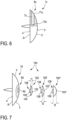
- the condylar implant 1d after Fig. 7 has at least one second coupling section 8d.
- the second coupling section 8d is set up for non-positive and/or positive, releasable coupling with a compensation element 100.
- the compensation element 100 serves to dimensionally compensate for a defect D of the tibial plateau TP (see Fig. 2 ). Together with the at least one compensation element 100, the condylar implant 1d forms an implant system 10d.
- the second coupling section 8d is arranged in the area of the lateral condylar surface 3.
- the condylar implant 1d has a further second coupling section, which in Fig. 7 is not apparent. This further second coupling section is arranged in the area of the medial condylar surface 2.
- the compensation element 100 has a complementary coupling section 108.
- the complementary coupling section 108 is arranged on a rear side of the compensation element 100.
- the second coupling section 8d is a locking receptacle 9d.
- the complementary coupling section 108 of the compensation element 100 is a complementary locking section 109.
- the locking receptacle 9d is sunk into the front side V in the proximal direction.
- the complementary locking section 109 protrudes proximally from the back of the compensation element 100.
- the compensation element 100 has a distal contact surface 103 and a proximal rear surface 104.
- the contact surface 103 is arranged on a front side of the compensation element.
- the contact surface 103 is set up for articulation with the tibial plateau TP.
- the contact surface 103 is convex.
- the contact surface 103 is smaller than the condylar surfaces 2, 3.
- the contact surface 103 contacts the medial tibial plateau TPM or the lateral tibial plateau TPL.
- the rear surface 104 rests on the front V of the condylar implant 1d.
- the implant system 10d has several different compensation elements 100, 100', 100". These are also referred to as first compensation element 100, second compensation element 100' and third compensation element 100".
- the multiple compensation elements 100, 100', 100" can be connected to the condylar implant 1d in an interchangeable manner. Accordingly, the second and third compensation elements 100', 100" each have a coupling section/locking section 108, 109, which is identical to the coupling section 108/locking section 109 of the first compensation element 100.
- the compensation elements 100, 100', 100" differ in terms of a proximodistal thickness t1, t2, t3 and are used to compensate for defects of varying severity. Depending on the severity of the defect, a comparatively thin or a comparatively thick compensation element is used.
- the first compensation element 100 has a first thickness t1.
- the second compensation element 100' has a second thickness t2.
- the third compensation element 100 has a third thickness t3.
- the first thickness t1 is smaller than the second thickness t2 and the third thickness t3.
- the second thickness t2 is larger than the first thickness t1 and smaller than the third thickness t3.
- the third thickness t3 is larger than the first thickness t1 and than the second thickness t2.
- an unspecified outer diameter of the compensation elements 100, 100', 100" is identical. Due to the different thicknesses t1, t2, t3, the respective contact surfaces 103, 103', 103" are curved to different degrees. Alternatively, compensation elements with different outside diameters are conceivable.
- the implant system 10d can have more or less than the three compensation elements 100, 100', 100" shown.
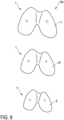
- Fig. 8 shows a further embodiment of an implant system 10e according to the invention.
- the implant system 10e includes several different trial condylar implants 1, 1', 1", which are also referred to below as first condylar implant 1, second condylar implant 1' and third condylar implant 1".
- the different condylar implants 1, 1', 1" have different sizes L, M, S.
- the differently sized condylar implants 1, 1', 1" are intended for trial attachment to femur bones of different sizes.
- the condylar implants 1, 1', 1" differ in terms of their mediolateral and/or anteroposterior dimensions.
- the proximodistal dimensions of the condylar implants 1, 1', 1" are different, which, however, is in Fig. 8 is not apparent.
- the sizes L, M, S can also be interpreted as large, medium and small.
- condylar implants 1, 1a, 1b, 1c and 1d can be combined with one another as desired to create further feature combinations.
- a condylar implant according to the invention has at least a first coupling section and a second coupling section.
- the fastening sections of the condylar implants 1c, 1d can each be designed as a through hole.
- an implant system according to the invention has, on the one hand, condylar implants of different sizes and, on the other hand, several different compensation elements, which can be optionally attached to each of the different condylar implants.
Landscapes
- Health & Medical Sciences (AREA)
- Orthopedic Medicine & Surgery (AREA)
- Transplantation (AREA)
- Heart & Thoracic Surgery (AREA)
- Cardiology (AREA)
- Oral & Maxillofacial Surgery (AREA)
- Engineering & Computer Science (AREA)
- Biomedical Technology (AREA)
- Physical Education & Sports Medicine (AREA)
- Vascular Medicine (AREA)
- Life Sciences & Earth Sciences (AREA)
- Animal Behavior & Ethology (AREA)
- General Health & Medical Sciences (AREA)
- Public Health (AREA)
- Veterinary Medicine (AREA)
- Prostheses (AREA)
Abstract
Die Erfindung betrifft ein femorales Probekondylenimplantat (1, 1a, 1b, 1c, 1d) zur probeweisen Anbringung an einem resezierten Femur (F) bei einer Kniegelenkersatzoperation, aufweisend eine distale Vorderseite (V) mit einer medialen Kondylenfläche (2), welche zur Artikulation mit einem medialen Tibiaplateau (TPM) einer proximalen Tibia (T) eingerichtet ist, und mit einer lateralen Kondylenfläche (3), welche zur Artikulation mit einem lateralen Tibiaplateau (TPL) der proximalen Tibia eingerichtet ist, und aufweisend eine proximale Rückseite (R), wobei die Rückseite eben ist und eine flache Knochenkontaktfläche (4) bildet, welche zur Kontaktierung einer distalen Schnittfläche (SF) des distal resezierten Femurs eingerichtet ist.
Description
- Die Erfindung betrifft ein femorales Probekondylenimplantat zur probeweisen Anbringung an einem resezierten Femur bei einer Kniegelenkersatzoperation.
- Bei einer Kniegelenkersatzoperation (englisch: Total Knee Arthroplasty (TKA)) werden abgenutzte oder anderweitig durch Krankheit oder einen Unfall beeinträchtigte Gelenkflächen des Femurs und/oder der Tibia durch künstliche Gelenkflächen einer Kniegelenkprothese ersetzt. Solche Kniegelenkprothesen umfassen üblicherweise eine Femurkomponente und eine Tibiakomponente. Die Femurkomponente wird am distalen Ende des Femurs implantiert. Die Tibiakomponente wird am proximalen Ende der Tibia implantiert.
- Vor der Implantation der prothetischen Komponenten werden der distale Femur und die proximale Tibia reseziert. Hierfür bringt der Chirurg unterschiedliche Resektionsschnitte an und trennt Knochen- und/oder Knorpelmaterial von dem jeweiligen Knochen ab. Durch die Resektion wird der jeweilige Knochen in seiner Form an die aufzunehmende prothetische Komponente angepasst.
- Die Resektion kann auf der Grundlage unterschiedlicher Konzepte ausgeführt werden. Ein Konzept zielt darauf ab, die Spannungen der Bänder des Knies bei der Gelenkbewegung ausgeglichen zu halten. Hierdurch soll eine bessere Funktion der Kniegelenkprothese gewährleistet werden. Dieses Konzept wird allgemein als "gap balancing" bezeichnet. Bei anderen Konzepten entfernt der Chirurg mittels der Resektion eine bestimmte Menge an Knochen- und/oder Knorpelmaterial. Solche Konzepte werden allgemein als "measured resection" bezeichnet. Die Ausrichtung der Resektionsschnitte in Bezug auf die Anatomie des Patienten bestimmt die spätere Ausrichtung der implantierten Komponenten und folglich auch die Orientierung der prothetischen Gelenkachsen. Die Ausrichtung der Resektionsschnitte ist daher von besonderer Bedeutung.
- Bei der Ausrichtung der Resektionsschnitte werden in erster Linie drei Ansätze unterschieden: mechanisch, anatomisch und kinematisch. Bei der mechanischen Ausrichtung wird die proximale Tibia senkrecht zur Längsachse des Tibiaschafts reseziert. Die Resektion des distalen Femurs erfolgt entsprechend hieran angepasst. Erforderlichenfalls werden Bandentlastungen (englisch: ligament releases) durchgeführt. Bei der anatomischen Ausrichtung wird versucht, die Tibia in einem Varus-Winkel von 3° zu resezieren. Die Femurresektion und Bandentlastungen werden mit dem Ziel einer geraden Hüft-Knie-Knöchel-Achse des Beins durchgeführt. Ziel der kinematischen Ausrichtung (englisch: kinematic alignment, nachfolgend abgekürzt als KA) ist es, die künstlichen Gelenkflächen der prothetischen Komponenten auf dem Niveau der präarthritischen, defektfreien natürlichen Gelenkflächen zu implantieren.
- Bei einer KA erfolgt die Ausrichtung der Resektionsschnitte oftmals ausgehend von dem distalen Femur. Die Resektion der proximalen Tibia erfolgt hieran angepasst. In diesem Zusammenhang wird auch von einer Übertragung der Ausrichtungen und/oder Schnitte gesprochen. Zu diesem Zweck sind spezielle chirurgische Instrumente bekannt, die auch als tibiales Ausricht- und/oder Übertragungswerkzeug (tibial cut alignment guide) bezeichnet werden. Solche Instrumente erlauben eine Übertragung der Ausrichtung der femoralen Resektionsschnitte auf die Tibia. Die Übertragung erfolgt üblicherweise nach einer wenigstens distalen Resektion des Femurs, bei welcher die distalen Kondylen abgetrennt werden. Die Übertragung kann in Extension oder Flexion erfolgen.
- Vor diesem Hintergrund besteht ein grundsätzlicher Bedarf nach chirurgischen Instrumenten, Probeimplantaten und Implantaten zur Umsetzung des Kinematic Alignment. Im Speziellen besteht ein Bedarf nach Instrumenten und Probeimplantaten, die eine Übertragung der Ausrichtung der Resektionsschnitte von dem distalen Femur auf die proximale Tibia ermöglichen.
- Aus der
US 10,912,658 B2 - Aufgabe der Erfindung ist es, eine verbesserte Übertragung der Ausrichtung der Resektionsschnitte im Rahmen des Kinematic Alignment zu ermöglichen.
- Diese Aufgabe wird durch das Bereitstellen eines femoralen Probekondylenimplantats mit den Merkmalen des Anspruchs 1 gelöst.
- Das erfindungsgemäße femorale Probekondylenimplantat ist zur probeweisen Anbringung an einem resezierten Femur bei einer Kniegelenkersatzoperation vorgesehen und weist auf: eine distale Vorderseite mit einer medialen Kondylenfläche, welche zur Artikulation mit einem medialen Tibiaplateau einer proximalen Tibia eingerichtet ist, und mit einer lateralen Kondylenfläche, welche zur Artikulation mit einem lateralen Tibiaplateau der proximalen Tibia eingerichtet ist. Zudem weist das erfindungsgemäßen femorale Probekondylenimplantat eine proximale Rückseite auf, wobei die Rückseite eben ist und eine flache Knochenkontaktfläche bildet, welche zur Kontaktierung einer distalen Schnittfläche des distal resezierten Femurs eingerichtet ist. Durch die erfindungsgemäße Lösung kann der proximale Tibiaschnitt vor dem Anbringen der anterioren und posterioren Femurschnitte ausgerichtet werden. Zu diesem Zweck ist die Rückseite des Probekondylenimplantats eben und bildet die besagte flache Knochenkontaktfläche. Die flache Knochenkontaktfläche ist zur Kontaktierung der distalen Schnittfläche des Femurs eingerichtet. Die distale Schnittfläche resultiert aus einem distalen Femurschnitt. Im Unterschied zu aus dem Stand der Technik bekannten Lösungen erlaubt die Erfindung eine verbesserte Ausrichtung der anterioren und posterioren Femurschnitte. Deren Ausrichtung kann erforderlichenfalls auch nach der Ausrichtung des Tibiaschnitts festgelegt und/oder korrigiert werden. Bei aus dem Stand der Technik bekannten Lösungen ist dies nicht ohne weiteres möglich, da die anterioren und posterioren Femurschnitte bereits vor dem Anbringen des Probeimplantats und der hierauf basierenden Ausrichtung des Tibiaschnitts angebracht sein müssen. Die beiden Kondylenflächen des Probekondylenimplantats ersetzen die abgetrennten natürlichen distalen Kondylen des Femurs. Die natürlichen anterioren und posterioren Femurkondylen werden dementgegen nicht ersetzt. Das Probekondylenimplantat weist keine Flächen auf, welche anstelle der natürlichen anterioren und posterioren Femurkondylen treten. In der Verwendung des Probekondylenimplantats sind die natürlichen anterioren und posterioren Femurkondylen üblicherweise nicht oder noch nicht abgetrennt. Die probeweise Anbringung erfolgt bei unterschiedlichen Ausgestaltungen auf unterschiedliche Weise, beispielsweise stoff-, kraft- und/oder formschlüssig.
- Die in dieser Beschreibung verwendeten Lage- und Richtungsbezeichnungen beziehen sich auf den Körper eines Patienten, insbesondere dessen Femur, und sind insoweit gemäß ihrer üblichen anatomischen Bedeutung zu verstehen. Folglich bedeutet "anterior" vordere(r) oder vorne liegend, "posterior" hintere(r) oder hinten liegend, "medial" innere(r) oder innen liegend, "lateral" äußere(r) oder außen liegend, "proximal" zum Körperzentrum hin und "distal" vom Körperzentrum entfernt. Weiter bedeuten "proximodistal" entlang, vorzugsweise parallel zu, einer proximal-distal ausgerichteten Achse, "anteroposterior" entlang, vorzugsweise parallel zu, einer anterior-posterior ausgerichteten Achse und "mediolateral" entlang, vorzugsweise parallel zu, einer medial-lateral ausgerichteten Achse. Die besagten Achsen sind orthogonal zueinander ausgerichtet und können selbstverständlich in Bezug zu nicht mit der Anatomie des Patienten in Verbindung stehenden X-, Y- und Z-Achsen gesetzt werden. Beispielsweise kann die proximaldistale Achse alternativ als X-Achse bezeichnet werden. Die medial-laterale Achse kann als Y-Achse bezeichnet werden. Die anterior-posteriore Achse kann als Z-Achse bezeichnet werden. Zur verbesserten Veranschaulichung und der Einfachheit der Bezeichnungen wegen werden nachfolgend in erster Linie die besagten anatomischen Lage- und Richtungsbezeichnungen verwendet. Weiter werden Bezeichnungen wie "Vorderseite" in Bezug auf eine proximal gerichtete Blickrichtung verwendet. Dementgegen werden Bezeichnungen wie "Rückseite" in Bezug auf eine distal gerichtete Blickrichtung verwendet.
- In Ausgestaltung der Erfindung ist wenigstens ein Befestigungsabschnitt vorhanden und zur lösbaren Befestigung an dem distalen Femur eingerichtet. Bei einer Ausgestaltung dient der wenigstens eine Befestigungsabschnitt einer Aufnahme eines gesonderten Befestigungselements, beispielsweise eines Nagels, einer Schraube oder dergleichen. Bei einer weiteren Ausgestaltung bildet der wenigstens eine Befestigungsabschnitt selbst ein solches Befestigungselement. Durch den wenigstens einen Befestigungsabschnitt kann insbesondere auf eine stoffschlüssige Anbringung des Probekondylenimplantats verzichtet werden. Dies kann die Verwendung des Probekondylenimplantats vereinfachen.
- Bei einer Ausgestaltung der Erfindung ist der wenigstens eine Befestigungsabschnitt eine proximodistal zwischen der Vorderseite und der Rückseite längserstreckte Durchgangsbohrung, welche zur Aufnahme eines zylindrischen Befestigungsstifts eingerichtet ist. Der zylindrische Befestigungsstift kann ausgehend von der Vorderseite durch die Durchgangsbohrung in den distalen Femur eingebracht werden. Der zylindrische Befestigungsstift kann beispielsweise eine Schraube, ein Nagel oder dergleichen sein. Vorzugsweise sind wenigstens zwei Durchgangsbohrungen vorhanden. In diesem Fall ist vorzugsweise eine erste Durchgangsbohrung auf der medialen Kondylenfläche angeordnet und eine zweite Durchgangsbohrung ist auf der lateralen Kondylenfläche angeordnet.
- In weiterer Ausgestaltung der Erfindung ist der wenigstens eine Befestigungsabschnitt ein proximal von der Rückseite aufragender zylindrischer Befestigungsstift. Bei dieser Ausgestaltung kann das Probekondylenimplantat zur Anbringung an dem resezierten Femur mit dem zylindrischen Befestigungsstift voran auf die distale Schnittfläche gedrückt werden. Hierbei dringt der zylindrische Befestigungsstift in den distal resezierten Femur ein und bewirkt eine kraftschlüssige lösbare Befestigung. Vorzugsweise ist der zylindrische Befestigungsstift an seinem proximalen Ende angespitzt. Vorzugsweise sind wenigstens zwei zylindrische Befestigungsstifte vorhanden. In diesem Fall ist ein erster zylindrischer Befestigungsstift rückseits der medialen Kondylenfläche angeordnet und ein zweiter zylindrischer Befestigungsstift ist rückseits der lateralen Kondylenfläche angeordnet. Bei dieser Ausgestaltung kann auf ein gesondertes Befestigungsmittel verzichtet werden. Das Befestigungsmittel, genauer der zylindrische Befestigungsstift, ist ein integraler Bestandteil und/oder einstückig angeformter Abschnitt des Probekondylenimplantats.
- In weiterer Ausgestaltung der Erfindung weist die Vorderseite wenigstens einen ersten Kopplungsabschnitt auf, welcher eingerichtet ist zur kraft- und/oder formschlüssigen lösbaren Kopplung mit einem tibialen Ausrichtinstrument zur Ausrichtung eines Tibiaschnittblocks. In gekoppeltem Zustand ist das tibiale Ausrichtinstrument relativ zu dem Probekondylenimplantat vorzugsweise fest und/oder unbeweglich positioniert. Das Probekondylenimplantat, genauer: dessen Ausrichtung, dient als Referenz für die Ausrichtung des Tibiaschnittblocks und damit auch für die Ausrichtung des Tibiaschnitts. Die Ausrichtung wird mittels des angekoppelten tibialen Ausrichtinstruments von dem Probekondylenimplantat auf den Tibiaschnittblock übertragen. Bei unterschiedlichen Ausgestaltungen ist der wenigstens eine erste Kopplungsabschnitt unterschiedlich gestaltet, beispielsweise als Aufnahmebohrung, Aufnahmeaussparung, Aufnahmenut oder dergleichen. Die lösbare Kopplung kann eine Steck-, Rast-, Klemm- und/oder Schnappverbindung sein. Vorzugsweise sind wenigstens zwei erste Kopplungsabschnitte vorhanden und mediolateral voneinander beabstandet an der Vorderseite angeordnet.
- In weiterer Ausgestaltung der Erfindung ist der wenigstens eine erste Kopplungsabschnitt eine in die Vorderseite eingebrachte und anteroposterior längserstreckte Aufnahmebohrung. Die anteroposteriore Längserstreckung erlaubt ein besonders einfaches Ankoppeln des tibialen Ausrichtinstruments. Bei einer Ausgestaltung ist die Aufnahmebohrung als Durchgangsbohrung ausgeführt. Bei einer weiteren Ausgestaltung ist die Aufnahmebohrung ein einends offenes Sackloch. In diesem Fall kann die Öffnung anterior oder posterior an der Vorderseite angeordnet sein. Vorzugsweise ist die Öffnung anterior angeordnet. Vorzugsweise sind wenigstens zwei Aufnahmebohrungen vorhanden und mediolateral voneinander beabstandet an der Vorderseite angeordnet.
- In weiterer Ausgestaltung der Erfindung weist die Vorderseite wenigstens einen zweiten Kopplungsabschnitt auf, welcher eingerichtet ist zur kraft- und/oder formschlüssigen lösbaren Kopplung mit einem Kompensationselement zur maßlichen Kompensation eines Defekts des Tibiaplateaus. Dies ist eine besonders vorteilhafte Ausgestaltung der Erfindung. Defekte des Tibiaplateaus, d.h. arthritische oder anderweitig bedingte Knochen- und/oder Knorpelabnutzungen, können bei der Ausrichtung des Tibiaschnitts auf einfache Weise maßlich ausgeglichen werden. Zu diesem Zweck ist der wenigstens eine zweite Kopplungsabschnitt an der Vorderseite vorhanden und dient einer lösbaren Kopplung mit dem besagten Kompensationselement. In angekoppeltem Zustand überdeckt das Kompensationselement die mediale Kondylenfläche und/oder die laterale Kondylenfläche. Anstelle der jeweiligen Kondylenfläche gelangt das Kompensationselement zur Anlage an dem betreffenden Abschnitt des Tibiaplateaus. Bei unterschiedlichen Ausgestaltungen ist die lösbare Kopplung unterschiedlich ausgeführt und/oder der wenigstens eine zweite Kopplungsabschnitt unterschiedlich gestaltet. Die lösbare Kopplung kann beispielsweise eine Steck-, Klemm-, Rast-und/oder Schnappverbindung sein. Vorzugsweise weist die Vorderseite wenigstens zwei zweite Kopplungsabschnitte auf, welche mediolateral voneinander beabstandet angeordnet sind. In diesem Fall ist vorzugsweise einer der beiden zweiten Kopplungsabschnitte auf der medialen Kondylenfläche angeordnet und ein weiterer der beiden zweiten Kopplungsabschnitte ist auf der lateralen Kondylenfläche angeordnet.
- Die Erfindung betrifft zudem ein Implantatsystem zur Verwendung bei einer Kniegelenkersatzoperation mit wenigstens einem femoralen Probekondylenimplantat gemäß der vorhergehenden Ausgestaltung und mit wenigstens einem Kompensationselement, welches zur kraft- und/oder formschlüssigen lösbaren Kopplung mit dem wenigstens einen zweiten Kopplungsabschnitt des Probekondylenimplantats und zur maßlichen Kompensation eines Defekts des Tibiaplateaus eingerichtet ist.
- In weiterer Ausgestaltung der Erfindung sind mehrere unterschiedliche Kompensationselemente vorhanden, wobei die unterschiedlichen Kompensationselemente unterschiedliche proximodistale Dicken zur maßlichen Kompensation unterschiedlich stark ausgeprägter Defekte aufweisen. Die unterschiedlichen Kompensationselemente können wahlweise und je nach Ausprägung eines vorliegenden Defekts an der Vorderseite des Probekondylenimplantats angebracht werden.
- Die Erfindung betrifft zudem ein Implantatsystem zur Verwendung bei einer Kniegelenkersatzoperation mit mehreren femoralen Probekondylenimplantaten nach einer der vorhergehenden Ausgestaltungen, wobei die mehreren Probekondylenimplantate unterschiedlich groß und zur probeweisen Anbringung an unterschiedlich großen Femurknochen eingerichtet sind. Mit anderen Worten weisen die mehreren Probekondylenimplantate unterschiedliche Größen auf. Die mehreren Probekondylenimplantate unterscheiden sich bei einer Ausgestaltung im Hinblick auf eine mediolaterale Abmessung der Vorderseite und/oder der Rückseite. Bei einer weiteren Ausgestaltung unterscheiden sich die mehreren Probekondylenimplantate alternativ oder zusätzlich hinsichtlich einer anteroposterioren Abmessung der Vorderseite und/oder Rückseite. Bei einer weiteren Ausgestaltung unterscheiden sich die mehreren Probekondylenimplantate alternativ oder zusätzlich im Hinblick auf eine zwischen der Vorderseite und der Rückseite erstreckte proximodistale Dicke.
- Weitere Vorteile und Merkmale der Erfindung ergeben sich aus den Ansprüchen sowie aus der nachfolgenden Beschreibung bevorzugter Ausführungsbeispiele der Erfindung, die anhand der Zeichnungen dargestellt sind.
- Fig. 1
- zeigt in schematischer Darstellung und in proximaler Blickrichtung eine Ausführungsform eines erfindungsgemäßen femoralen Probekondylenimplantats in einem an einem distalen Femur angebrachten Zustand,
- Fig. 2, 3
- unterschiedliche Ansichten einer exemplarischen intraoperativen Situation unter Verwendung des femoralen Probekondylenimplantats in einer posterioren Blickrichtung (
Fig. 2 ) und einer medialen Blickrichtung (Fig. 3 ), - Fig. 4
- eine weitere Ausführungsform eines erfindungsgemäßen femoralen Probekondylenimplantats in einer schematischen, teilweise freigeschnittenen Seitenansicht in medialer Blickrichtung,
- Fig. 5
- eine weitere Ausführungsform eines erfindungsgemäßen femoralen Probekondylenimplantats in einer schematischen Seitenansicht in medialer Blickrichtung,
- Fig. 6
- eine weitere Ausführungsform eines erfindungsgemäßen femoralen Probekondylenimplantats in schematischer, teilweise freigeschnittener Seitenansicht in medialer Blickrichtung,
- Fig. 7
- eine Ausführungsform eines erfindungsgemäßen Implantatsystems mit einer weiteren Ausführungsform eines erfindungsgemäßen femoralen Probekondylenimplantats und mit mehreren unterschiedlichen Kompensationselementen, wobei das Implantatsystem in einer schematischen, teilweise freigeschnittenen Seitenansicht in medialer Blickrichtung dargestellt ist, und
- Fig. 8
- eine weitere Ausführungsform eines erfindungsgemäßen Implantatsystems mit mehreren unterschiedlichen femoralen Probekondylenimplantaten, wobei das Implantatsystem schematisch in einer proximalen Blickrichtung dargestellt ist.
- Gemäß den
Fig. 1 bis 3 ist ein femorales Probekondylenimplantat 1 zur Verwendung bei einer Kniegelenkersatzoperation vorgesehen. Das femorale Probekondylenimplantat 1 wird nachfolgend der Kürze wegen als Kondylenimplantat bezeichnet. - Das Kondylenimplantat 1 ist zur probeweisen Anbringung an einem distalen Femur F eingerichtet und weist eine distale Vorderseite V und eine der Vorderseite V proximal gegenüberliegende Rückseite R auf.
- In der Verwendung des Kondylenimplantats 1 ist die Rückseite R proximal orientiert und dem distalen Femur F zugewandt. Die Vorderseite V ist distal orientiert und einer proximalen Tibia, genauer: deren Tibiaplateau TP, zugewandt.
- Die Vorderseite V weist eine mediale Kondylenfläche 2 und eine laterale Kondylenfläche 3 auf. Die mediale Kondylenfläche 2 ist zur Artikulation mit einem medialen Abschnitt des Tibiaplateaus TP eingerichtet. Dieser Abschnitt kann auch als mediales Tibiaplateau TPL bezeichnet werden. Die laterale Kondylenfläche 3 ist zur Artikulation mit einem lateralen Abschnitt des Tibiaplateaus TP eingerichtet. Dieser Abschnitt des Tibiaplateaus TP kann auch als laterales Tibiaplateau TPL bezeichnet werden.
- Die Rückseite R ist eben und bildet eine flache Knochenkontaktfläche 4. Die flache Knochenkontaktfläche 4 ist zur Kontaktierung einer distalen Schnittfläche SF des distal resezierten Femurs F eingerichtet. In der anhand der
Fig. 1 bis 3 gezeigten intraoperativen Situation ersetzen die beiden Kondylenflächen 2, 3 des Kondylenimplantats 1 die natürlichen distalen Kondylenflächen des Femurs F. Diese wurden vor Anbringung des Kondylenimplantats 1 auf eine dem Fachmann bekannte Weise mittels eines distalen Femurschnitts abgetrennt. Der Femur F verfügt nach wie vor über seine anterioren Kondylenflächen AK und seine posterioren Kondylenflächen PK. Die anterioren Kondylenflächen AK und die posterioren Kondylenflächen PK werden - im Gegensatz zu den natürlichen distalen Kondylenflächen - mittels des Kondylenimplantats 1 nicht ersetzt. Die beiden Kondylenflächen 2, 3 simulieren eine distale Kondylenlinie KL des Femurs (sieheFig. 2 ). - Die mediale Kondylenfläche 2 und die laterale Kondylenfläche 3 sind konvex gewölbt und in ihrer Form einer Form der natürlichen distalen Kondylen des Femurs F nachempfunden. Es versteht sich, dass die in den Figuren gezeigte Formgebung der Kondylenflächen 2, 3 als rein exemplarisch anzusehen ist.
- Das Kondylenimplantat 1 wird lediglich probeweise an dem Femur F angebracht. Die Anbringung erfolgt bei unterschiedlichen Ausgestaltungen auf unterschiedliche Weise. Bei einer in den Figuren nicht gezeigten Ausführungsform ist eine stoffschlüssige Verbindung vorgesehen. Zu diesem Zweck kann die Rückseite R mit der distalen Schnittfläche SF stoffschlüssig zusammengefügt werden. Hierfür geeignete medizinische Klebstoffe oder dergleichen sind dem Fachmann bekannt.
- Bei den in den Figuren gezeigten Ausführungsformen ist eine kraftschlüssige lösbare Befestigung vorgesehen. Zu diesem Zweck weist das Kondylenimplantat 1 wenigstens einen Befestigungsabschnitt 5 auf. Der Befestigungsabschnitt 5 ist bei unterschiedlichen Ausgestaltungen unterschiedlich ausgeführt.
- Bei der gezeigten Ausführungsform weist das Kondylenimplantat 1 zwei Befestigungsabschnitte 5, 5' auf (siehe
Fig. 1 ). Die beiden Befestigungsabschnitte 5, 5' sind mediolateral voneinander beabstandet angeordnet und können auch als lateraler Befestigungsabschnitt 5 und medialer Befestigungsabschnitt 5' bezeichnet werden. Die beiden Befestigungsabschnitte 5, 5' sind abgesehen von ihrer unterschiedlichen Anordnung identisch gestaltet. Weitere Details der Befestigungsabschnitte 5, 5' werden deshalb nachfolgend zur Vermeidung von Wiederholungen lediglich in Bezug auf einen der beiden Befestigungsabschnitte 5, 5' näher erläutert. Das diesbezüglich Gesagte gilt für beide Befestigungsabschnitte 5, 5`. - Das Kondylenimplantat 1 weist bei der gezeigten Ausführungsform einen einstückigen Aufbau auf. Alternativ denkbar ist eine mehrteilige Gestaltung. Als Werkstoff kommen für medizinische Anwendungen geeignete Metalle oder Kunststoffe infrage. Solche Werkstoffe sind dem Fachmann bekannt.
- Die
Fig. 4 bis 7 zeigen weitere Ausführungsformen erfindungsgemäßer femoraler Probekondylenimplantate 1a, 1b, 1c, 1d. Der Aufbau und die Funktionsweise der Kondylenimplantate 1a, 1b, 1c, 1d sind prinzipiell identisch mit dem Aufbau und der Funktionsweise des Kondylenimplantats 1 nach denFig. 1 bis 3 . Zur Vermeidung von Wiederholungen werden daher nachfolgend lediglich wesentliche Unterschiede der Kondylenimplantate 1a, 1b, 1c, 1d erläutert. Funktionsgleiche Abschnitte werden nicht bei jeder Ausführungsform beschrieben. Stattdessen wird auf das diesbezüglich im Zusammenhang mit dem Kondylenimplantat 1 nach denFig. 1 bis 3 Gesagte verwiesen und ausdrücklich Bezug genommen. - Bei dem Kondylenimplantat 1a nach
Fig. 4 ist der Befestigungsabschnitt 5 eine Durchgangsbohrung 5a. Die Durchgangsbohrung 5a ist zwischen der Vorderseite V und der Rückseite R durchgängig längserstreckt. Die Durchgangsbohrung 5a weist eine auf der Vorderseite V angeordnete distale Öffnung 51a und eine auf der Rückseite R angeordnete proximale Öffnung 52a auf. Die Durchgangsbohrung 5a ist entlang einer proximodistalen Achse durch das Kondylenimplantat 1a erstreckt. Die Durchgangsbohrung 5a ist zur Aufnahme eines in den Figuren nicht gezeigten zylindrischen Befestigungsstifts eingerichtet. Solche Befestigungsstifte sind dem Fachmann bekannt und können beispielsweise als Schraube, Nagel, Pin oder dergleichen gestaltet sein. Zur probeweisen Anbringung des Kondylenimplantats 1a an dem distalen Femur F wird die Rückseite R mit der distalen Schnittfläche SF kontaktiert. Hiernach wird der besagte zylindrische Befestigungsstift ausgehend von der Vorderseite V durch die distale Öffnung 51a in die Durchgangsbohrung 5a eingeführt und über die proximale Öffnung 52a in die distale Schnittfläche SF eingebracht. - Bei dem Kondylenimplantat 1b nach
Fig. 5 ist der Befestigungsabschnitt 5 ein zylindrischer Befestigungsstift 5b. Der Befestigungsstift 5b ragt in proximaler Richtung von der Rückseite R ab. Der Befestigungsstift 5b weist ein distales Ende 51b und ein proximales Ende 52b auf. Der Befestigungsstift 5b ist zwischen dem distalen Ende 51b und dem proximalen Ende 52b längserstreckt. Das distale Ende 51b ist fest mit der Rückseite R verbunden. Das proximale Ende 52b ist vorliegend angespitzt. Bei der gezeigten Ausführungsform ist der Befestigungsstift 5b einstückig zusammenhängend mit den übrigen Abschnitten des Kondylenimplantats 1b. Bei einer in den Figuren nicht gezeigten Ausführungsform ist der Befestigungsstift ein gesondert gefertigtes und hiernach fest mit der Rückseite zusammengefügtes Bauteil. Zur probeweisen Anbringung des Kondylenimplantats 1 wird die Rückseite R gegenüber der distalen Schnittfläche F positioniert und der Befestigungsstift 5b wird manuell in die Knochenstruktur des Femurs F eingedrückt. - Bei dem Kondylenimplantat 1c nach
Fig. 6 ist ein erster Kopplungsabschnitt 6c vorhanden. Der erste Kopplungsabschnitt 6c dient einer kraft- und/oder formschlüssigen lösbaren Kopplung mit einem tibialen Ausrichtinstrument zur Ausrichtung eines Tibiaschnittblocks. Solche tibialen Ausrichtinstrumente sind dem Fachmann bekannt und dienen einer Übertragung der Orientierung der distalen Schnittfläche SF auf die proximale Tibia T. Der erste Kopplungsabschnitt 6c ist an der Vorderseite V angeordnet. Bei der gezeigten Ausführungsform ist der erste Kopplungsabschnitt 6c eine Aufnahmebohrung 7c. Die Aufnahmebohrung 7c ist anteroposterior längserstreckt und weist vorliegend eine anteriore Öffnung 71c und einen posterioren Anschlag 72c auf. Die Aufnahmebohrung 7c ist zwischen der Öffnung 71c und dem Anschlag 72c längserstreckt und insoweit als Sackbohrung ausgeführt. Die Aufnahmebohrung 7c ist zur Aufnahme eines komplementären Kopplungszapfens des besagten tibialen Ausrichtinstruments eingerichtet. Das Kondylenimplantat 1c weist vorliegend einen weiteren, inFig. 6 nicht ersichtlichen, ersten Kopplungsabschnitt auf. Dieser weitere Kopplungsabschnitt ist medial von dem inFig. 6 gezeigten ersten Kopplungsabschnitt 6c beabstandet und im Bereich der medialen Kondylenfläche 2 angeordnet. - Das Kondylenimplantat 1d nach
Fig. 7 weist wenigstens einen zweiten Kopplungsabschnitt 8d auf. Der zweite Kopplungsabschnitt 8d ist zur kraft- und/oder formschlüssigen lösbaren Kopplung mit einem Kompensationselement 100 eingerichtet. Das Kompensationselement 100 dient zur maßlichen Kompensation eines Defekts D des Tibiaplateaus TP (sieheFig. 2 ). Zusammen mit dem wenigstens einen Kompensationselement 100 bildet das Kondylenimplantat 1d ein Implantatsystem 10d. - Der zweite Kopplungsabschnitt 8d ist bei der gezeigten Ausführungsform im Bereich der lateralen Kondylenfläche 3 angeordnet. Das Kondylenimplantat 1d weist vorliegend einen weiteren zweiten Kopplungsabschnitt auf, welcher in
Fig. 7 nicht ersichtlich ist. Dieser weitere zweite Kopplungsabschnitt ist im Bereich der medialen Kondylenfläche 2 angeordnet. - Zur lösbaren Kopplung mit dem Kondylenimplantat 1d weist das Kompensationselement 100 einen komplementären Kopplungsabschnitt 108 auf. Der komplementäre Kopplungsabschnitt 108 ist an einer Rückseite des Kompensationselements 100 angeordnet.
- Bei der gezeigten Ausführungsform ist der zweite Kopplungsabschnitt 8d eine Rastaufnahme 9d. Dementsprechend ist der komplementäre Kopplungsabschnitt 108 des Kompensationselements 100 ein komplementärer Rastabschnitt 109. Die Rastaufnahme 9d ist in proximaler Richtung in die Vorderseite V eingesenkt. Der komplementäre Rastabschnitt 109 ragt proximal von der Rückseite des Kompensationselements 100 ab.
- Das Kompensationselement 100 weist eine distale Kontaktfläche 103 und eine proximale Rückfläche 104 auf. Die Kontaktfläche 103 ist an einer Vorderseite des Kompensationselements angeordnet. Die Kontaktfläche 103 ist zur Artikulation mit dem Tibiaplateau TP eingerichtet. Die Kontaktfläche 103 ist konvex. Die Kontaktfläche 103 ist kleiner als die Kondylenflächen 2, 3. Je nachdem, ob das Kompensationselement 100 lateral oder medial an der Vorderseite V des Kondylenimplantats 1 angebracht ist, kontaktiert die Kontaktfläche 103 das mediale Tibiaplateau TPM oder das laterale Tibiaplateau TPL. In angebrachtem Zustand liegt die Rückfläche 104 an der Vorderseite V des Kondylenimplantats 1d an.
- Bei der gezeigten Ausführungsform weist das Implantatsystem 10d mehrere unterschiedliche Kompensationselemente 100, 100', 100" auf. Diese werden auch als erstes Kompensationselement 100, zweites Kompensationselement 100' und drittes Kompensationselement 100" bezeichnet.
- Die mehreren Kompensationselemente 100, 100', 100" sind gegeneinander austauschbar mit dem Kondylenimplantat 1d verbindbar. Dementsprechend weisen das zweite und dritte Kompensationselement 100', 100" jeweils einen Kopplungsabschnitt/Rastabschnitt 108, 109 auf, welcher identisch zu dem Kopplungsabschnitt 108/Rastabschnitt 109 des ersten Kompensationselements 100 ist.
- Die Kompensationselemente 100, 100`, 100" unterscheiden sich hinsichtlich einer proximodistalen Dicke t1, t2, t3 und dienen zur maßlichen Kompensation unterschiedlich stark ausgeprägter Defekte. Je nach Ausprägung des Defekts kommt ein vergleichsweise dünnes oder ein vergleichsweise dickes Kompensationselement zum Einsatz.
- Im Speziellen weist das erste Kompensationselement 100 eine erste Dicke t1 auf. Das zweite Kompensationselement 100' weist eine zweite Dicke t2 auf. Das dritte Kompensationselement 100 weist eine dritte Dicke t3 auf. Vorliegend ist die erste Dicke t1 kleiner als die zweite Dicke t2 und die dritte Dicke t3. Die zweite Dicke t2 ist größer als die erste Dicke t1 und kleiner als die dritte Dicke t3. Die dritte Dicke t3 ist größer als die erste Dicke t1 und als die zweite Dicke t2.
- Bei der gezeigten Ausführungsform ist ein nicht näher bezeichneter Außendurchmesser der Kompensationselemente 100, 100', 100" identisch. Aufgrund der unterschiedlichen Dicken t1, t2, t3 sind die jeweiligen Kontaktflächen 103, 103', 103" unterschiedlich stark gewölbt. Alternativ sind Kompensationselemente mit unterschiedlichen Außendurchmessern denkbar.
- Es versteht sich, dass die gezeigte Anzahl an Kompensationselementen rein exemplarisch ist. Selbstverständlich kann das Implantatsystem 10d mehr oder weniger als die gezeigten drei Kompensationselemente 100, 100', 100" aufweisen.
-
Fig. 8 zeigt eine weitere Ausführungsform eines erfindungsgemäßen Implantatsystems 10e. Das Implantatsystem 10e umfasst mehrere unterschiedliche Probekondylenimplantate 1, 1', 1", die nachfolgend auch als erstes Kondylenimplantat 1, zweites Kondylenimplantat 1' und drittes Kondylenimplantat 1" bezeichnet werden. Die unterschiedlichen Kondylenimplantate 1, 1', 1" weisen unterschiedliche Größen L, M, S auf. Die unterschiedlich großen Kondylenimplantate 1, 1', 1" sind zur probeweisen Anbringung an unterschiedlich großen Femurknochen vorgesehen. - Bei der gezeigten Ausführungsform unterscheiden die Kondylenimplantate 1, 1', 1" sich hinsichtlich ihrer mediolateralen und/oder anteroposterioren Abmessungen. Zudem sind die proximodistalen Abmessungen der Kondylenimplantate 1, 1', 1" unterschiedlich, was jedoch in
Fig. 8 nicht ersichtlich ist. Die Größen L, M, S können auch als large, medium und small interpretiert werden. - Die Merkmale der Kondylenimplantate 1, 1a, 1b, 1c sowie 1d sind beliebig zu weiteren Merkmalskombinationen miteinander kombinierbar. Entsprechendes gilt sinngemäß für die Merkmale der Implantatsysteme 10d, 10e. Beispielsweise weist ein in den Figuren nicht gezeigtes erfindungsgemäßes Kondylenimplantat wenigstens einen ersten Kopplungsabschnitt und einen zweiten Kopplungsabschnitt auf. Zudem versteht sich, dass die Befestigungsabschnitte der Kondylenimplantate 1c, 1d, anders als in den Figuren gezeigt, jeweils als Durchgangsbohrung gestaltet sein können. Zudem weist ein in den Figuren nicht gezeigtes erfindungsgemäßes Implantatsystem zum einen unterschiedlich große Kondylenimplantate und zum anderen mehrere unterschiedliche Kompensationselemente auf, die wahlweise an jedem der unterschiedlichen Kondylenimplantate anbringbar sind.
Claims (10)
- Femorales Probekondylenimplantat (1, 1a, 1b, 1c, 1d) zur probeweisen Anbringung an einem resezierten Femur (F) bei einer Kniegelenkersatzoperation, aufweisendeine distale Vorderseite (V) mit einer medialen Kondylenfläche (2), welche zur Artikulation mit einem medialen Tibiaplateau (TPM) einer proximalen Tibia (T) eingerichtet ist, und mit einer lateralen Kondylenfläche (3), welche zur Artikulation mit einem lateralen Tibiaplateau (TPL) der proximalen Tibia (T) eingerichtet ist,und aufweisend eine proximale Rückseite (R),wobei die Rückseite (R) eben ist und eine flache Knochenkontaktfläche (4) bildet, welche zur Kontaktierung einer distalen Schnittfläche (SF) des distal resezierten Femurs (F) eingerichtet ist.
- Femorales Probekondylenimplantat (1, 1a, 1b, 1c, 1d) nach Anspruch 1, dadurch gekennzeichnet, dass wenigstens ein Befestigungsabschnitt (5, 5') vorhanden und zur lösbaren Befestigung an dem distalen Femur (F) eingerichtet ist.
- Femorales Probekondylenimplantat (1a) nach Anspruch 2, dadurch gekennzeichnet, dass der wenigstens eine Befestigungsabschnitt (5, 5') eine proximodistal zwischen der Vorderseite (V) und der Rückseite (R) längserstreckte Durchgangsbohrung (5a) ist, welche zur Aufnahme eines zylindrischen Befestigungsstifts eingerichtet ist.
- Femorales Probekondylenimplantat (1b) nach Anspruch 2, dadurch gekennzeichnet, dass der wenigstens eine Befestigungsabschnitt (5, 5') ein proximal von der Rückseite (R) aufragender zylindrischer Befestigungsstift (5b) ist.
- Femorales Probekondylenimplantat (1, 1a, 1b, 1c, 1d) nach einem der vorhergehenden Ansprüche, dadurch gekennzeichnet, dass die Vorderseite (V) wenigstens einen ersten Kopplungsabschnitt (6c) aufweist, welcher eingerichtet ist zur kraft- und/oder formschlüssigen lösbaren Kopplung mit einem tibialen Ausrichtinstrument zur Ausrichtung eines Tibiaschnittblocks.
- Femorales Probekondylenimplantat (1, 1a, 1b, 1c, 1d) nach Anspruch 5, dadurch gekennzeichnet, dass der wenigstens eine erste Kopplungsabschnitt (6c) eine in die Vorderseite (V) eingebrachte und anteroposterior längserstreckte Aufnahmebohrung (7c) ist.
- Femorales Probekondylenimplantat (1, 1a, 1b, 1c, 1d) nach einem der vorhergehenden Ansprüche, dadurch gekennzeichnet, dass die Vorderseite (V) wenigstens einen zweiten Kopplungsabschnitt (8d) aufweist, welcher eingerichtet ist zur kraft- und/oder formschlüssigen lösbaren Kopplung mit einem Kompensationselement (100) zur maßlichen Kompensation eines Defekts (D) des Tibiaplateaus (TP).
- Implantatsystem (10d) mit wenigstens einem femoralen Probekondylenimplantat (1, 1a, 1b, 1c, 1d) nach Anspruch 7 und mit wenigstens einem Kompensationselement (100), welches zur kraft- und/oder formschlüssigen lösbaren Kopplung mit dem wenigstens einen zweiten Kopplungsabschnitt (8d) des Probekondylenimplantats (1, 1a, 1b, 1c, 1d) und zur maßlichen Kompensation eines Defekts (D) des Tibiaplateaus (TP) eingerichtet ist.
- Implantatsystem (10d) nach Anspruch 8, dadurch gekennzeichnet, dass mehrere unterschiedliche Kompensationselemente (100, 100', 100") vorhanden sind, wobei die unterschiedlichen Kompensationselemente (100, 100`, 100") unterschiedliche proximodistale Dicken (t1, t2, t3) zur maßlichen Kompensation unterschiedlich stark ausgeprägter Defekte aufweisen.
- Implantatsystem (10e) mit mehreren femoralen Probekondylenimplantaten (1, 1a, 1b, 1c, 1d) nach einem der Ansprüche 1 bis 8, wobei die mehreren Probekondylenimplantate (1, 1a, 1b, 1c, 1d) unterschiedlich groß und zur probeweisen Anbringung an unterschiedlich großen Femurknochen eingerichtet sind.
Applications Claiming Priority (1)
| Application Number | Priority Date | Filing Date | Title |
|---|---|---|---|
| DE102022207580.3A DE102022207580A1 (de) | 2022-07-25 | 2022-07-25 | Femorales Probekondylenimplantat |
Publications (1)
| Publication Number | Publication Date |
|---|---|
| EP4311526A1 true EP4311526A1 (de) | 2024-01-31 |
Family
ID=87196409
Family Applications (1)
| Application Number | Title | Priority Date | Filing Date |
|---|---|---|---|
| EP23184113.1A Withdrawn EP4311526A1 (de) | 2022-07-25 | 2023-07-07 | Femorales probekondylenimplantat |
Country Status (4)
| Country | Link |
|---|---|
| US (1) | US20240024132A1 (de) |
| EP (1) | EP4311526A1 (de) |
| JP (1) | JP2024015979A (de) |
| DE (1) | DE102022207580A1 (de) |
Citations (7)
| Publication number | Priority date | Publication date | Assignee | Title |
|---|---|---|---|---|
| WO2014063084A1 (en) * | 2012-10-18 | 2014-04-24 | Smith & Nephew, Inc. | Alignment devices and methods |
| US20150045801A1 (en) * | 2010-05-21 | 2015-02-12 | Howmedica Osteonics Corp. | Natural alignment knee instruments |
| WO2017201256A2 (en) * | 2016-05-18 | 2017-11-23 | Depuy Ireland Unlimited Company | System and method for preparing a patient's femur in an orthopaedic joint replacement procedure |
| EP3395269A2 (de) * | 2009-05-29 | 2018-10-31 | Smith & Nephew, Inc | Vorrichtung zur durchführung von knie-arthroplastien |
| EP3760167A1 (de) * | 2019-06-30 | 2021-01-06 | DePuy Ireland Unlimited Company | Femurversuchskomponenten und zugehöriges orthopädisches operationsanwendungsverfahren |
| US10912658B2 (en) | 2015-04-20 | 2021-02-09 | Oxford University Innovation Limited | Arthroplasty apparatus and method |
| WO2022125303A1 (en) * | 2020-12-07 | 2022-06-16 | Microport Orthopedics Holdings Inc. | Tibial guide transfer instruments and methods |
Family Cites Families (2)
| Publication number | Priority date | Publication date | Assignee | Title |
|---|---|---|---|---|
| FR2810227B1 (fr) | 2000-06-19 | 2002-09-06 | Buttet Michel De | Dispositif de preparation et de coupe femorale et tibiale adapte a une prothese de genou unicompartimentale et destine a sa mise en place |
| US7780671B2 (en) * | 2006-01-23 | 2010-08-24 | Zimmer Technology, Inc. | Bone resection apparatus and method for knee surgery |
-
2022
- 2022-07-25 DE DE102022207580.3A patent/DE102022207580A1/de active Pending
-
2023
- 2023-07-04 JP JP2023109971A patent/JP2024015979A/ja active Pending
- 2023-07-07 EP EP23184113.1A patent/EP4311526A1/de not_active Withdrawn
- 2023-07-07 US US18/348,620 patent/US20240024132A1/en active Pending
Patent Citations (7)
| Publication number | Priority date | Publication date | Assignee | Title |
|---|---|---|---|---|
| EP3395269A2 (de) * | 2009-05-29 | 2018-10-31 | Smith & Nephew, Inc | Vorrichtung zur durchführung von knie-arthroplastien |
| US20150045801A1 (en) * | 2010-05-21 | 2015-02-12 | Howmedica Osteonics Corp. | Natural alignment knee instruments |
| WO2014063084A1 (en) * | 2012-10-18 | 2014-04-24 | Smith & Nephew, Inc. | Alignment devices and methods |
| US10912658B2 (en) | 2015-04-20 | 2021-02-09 | Oxford University Innovation Limited | Arthroplasty apparatus and method |
| WO2017201256A2 (en) * | 2016-05-18 | 2017-11-23 | Depuy Ireland Unlimited Company | System and method for preparing a patient's femur in an orthopaedic joint replacement procedure |
| EP3760167A1 (de) * | 2019-06-30 | 2021-01-06 | DePuy Ireland Unlimited Company | Femurversuchskomponenten und zugehöriges orthopädisches operationsanwendungsverfahren |
| WO2022125303A1 (en) * | 2020-12-07 | 2022-06-16 | Microport Orthopedics Holdings Inc. | Tibial guide transfer instruments and methods |
Also Published As
| Publication number | Publication date |
|---|---|
| DE102022207580A1 (de) | 2024-01-25 |
| JP2024015979A (ja) | 2024-02-06 |
| US20240024132A1 (en) | 2024-01-25 |
Similar Documents
| Publication | Publication Date | Title |
|---|---|---|
| DE69834363T2 (de) | Modulare Ausrüstung zur Vorbereitung eines Knochens und zur Prüfreduzierung orthopädischer Implantate | |
| DE10215358B4 (de) | Bänderspannvorrichtung mit Schnittlehre | |
| DE69130391T2 (de) | Fraese zur resektion von knochen | |
| DE60126527T2 (de) | Modulare Gelenkprothese | |
| EP0928172B1 (de) | Stiellose kniegelenkendoprothese | |
| DE602005001057T2 (de) | Satz von Knochenschutzausrüstungen | |
| DE69924193T2 (de) | Instrument zur auswertung des gleichgewichts eines kniegelenks | |
| DE3688207T2 (de) | Chirurgische Instrumente. | |
| US10022130B2 (en) | Polymer 4-in-1 femoral cutting block | |
| WO2002009596A1 (de) | Vorrichtung zur ausrichtung einer führungsschablone | |
| EP4245229B1 (de) | Chirurgisches instrument | |
| EP2747673B1 (de) | Schneidführung zum erzeugen einer aussenkontur für eine gelenkendoprothese | |
| DE102012201970B4 (de) | Verfahren und Vorrichtung zur Durchführung einer Arthroplastik | |
| EP4282346B1 (de) | Chirurgisches instrument | |
| EP1645229A1 (de) | Bänderkraft-Erfassungssystem | |
| DE60206772T2 (de) | Führung zur lokalisierung der resektionsflächen des femur | |
| DE102022207576A1 (de) | Chirurgisches Instrument und chirurgisches Instrumentensystem | |
| EP4311525B1 (de) | Chirurgisches instrument, femorales probeimplantat und chirurgisches instrumentensystem | |
| EP2774553A1 (de) | Femurschneidinstrument | |
| EP4285844A1 (de) | Chirurgisches instrument | |
| EP4344681A1 (de) | Modulares instrumentensystem zur verwendung bei einer kniegelenkersatzoperation | |
| DE102022207580A1 (de) | Femorales Probekondylenimplantat | |
| EP4311507A1 (de) | Chirurgisches instrument | |
| EP4282348B1 (de) | Chirurgisches instrument | |
| EP4295787B1 (de) | Chirurgische vorrichtung |
Legal Events
| Date | Code | Title | Description |
|---|---|---|---|
| PUAI | Public reference made under article 153(3) epc to a published international application that has entered the european phase |
Free format text: ORIGINAL CODE: 0009012 |
|
| STAA | Information on the status of an ep patent application or granted ep patent |
Free format text: STATUS: THE APPLICATION HAS BEEN PUBLISHED |
|
| AK | Designated contracting states |
Kind code of ref document: A1 Designated state(s): AL AT BE BG CH CY CZ DE DK EE ES FI FR GB GR HR HU IE IS IT LI LT LU LV MC ME MK MT NL NO PL PT RO RS SE SI SK SM TR |
|
| STAA | Information on the status of an ep patent application or granted ep patent |
Free format text: STATUS: THE APPLICATION IS DEEMED TO BE WITHDRAWN |
|
| 18D | Application deemed to be withdrawn |
Effective date: 20240801 |