EP4311525A1 - Chirurgisches instrument, femorales probeimplantat und chirurgisches instrumentensystem - Google Patents
Chirurgisches instrument, femorales probeimplantat und chirurgisches instrumentensystem Download PDFInfo
- Publication number
- EP4311525A1 EP4311525A1 EP23184058.8A EP23184058A EP4311525A1 EP 4311525 A1 EP4311525 A1 EP 4311525A1 EP 23184058 A EP23184058 A EP 23184058A EP 4311525 A1 EP4311525 A1 EP 4311525A1
- Authority
- EP
- European Patent Office
- Prior art keywords
- surgical instrument
- trial implant
- fixing
- fastening device
- positioning pins
- Prior art date
- Legal status (The legal status is an assumption and is not a legal conclusion. Google has not performed a legal analysis and makes no representation as to the accuracy of the status listed.)
- Granted
Links
Images


Classifications
-
- A—HUMAN NECESSITIES
- A61—MEDICAL OR VETERINARY SCIENCE; HYGIENE
- A61F—FILTERS IMPLANTABLE INTO BLOOD VESSELS; PROSTHESES; DEVICES PROVIDING PATENCY TO, OR PREVENTING COLLAPSING OF, TUBULAR STRUCTURES OF THE BODY, e.g. STENTS; ORTHOPAEDIC, NURSING OR CONTRACEPTIVE DEVICES; FOMENTATION; TREATMENT OR PROTECTION OF EYES OR EARS; BANDAGES, DRESSINGS OR ABSORBENT PADS; FIRST-AID KITS
- A61F2/00—Filters implantable into blood vessels; Prostheses, i.e. artificial substitutes or replacements for parts of the body; Appliances for connecting them with the body; Devices providing patency to, or preventing collapsing of, tubular structures of the body, e.g. stents
- A61F2/02—Prostheses implantable into the body
- A61F2/30—Joints
- A61F2/46—Special tools for implanting artificial joints
- A61F2/4684—Trial or dummy prostheses
-
- A—HUMAN NECESSITIES
- A61—MEDICAL OR VETERINARY SCIENCE; HYGIENE
- A61F—FILTERS IMPLANTABLE INTO BLOOD VESSELS; PROSTHESES; DEVICES PROVIDING PATENCY TO, OR PREVENTING COLLAPSING OF, TUBULAR STRUCTURES OF THE BODY, e.g. STENTS; ORTHOPAEDIC, NURSING OR CONTRACEPTIVE DEVICES; FOMENTATION; TREATMENT OR PROTECTION OF EYES OR EARS; BANDAGES, DRESSINGS OR ABSORBENT PADS; FIRST-AID KITS
- A61F2/00—Filters implantable into blood vessels; Prostheses, i.e. artificial substitutes or replacements for parts of the body; Appliances for connecting them with the body; Devices providing patency to, or preventing collapsing of, tubular structures of the body, e.g. stents
- A61F2/02—Prostheses implantable into the body
- A61F2/30—Joints
- A61F2/30721—Accessories
- A61F2/30749—Fixation appliances for connecting prostheses to the body
-
- A—HUMAN NECESSITIES
- A61—MEDICAL OR VETERINARY SCIENCE; HYGIENE
- A61F—FILTERS IMPLANTABLE INTO BLOOD VESSELS; PROSTHESES; DEVICES PROVIDING PATENCY TO, OR PREVENTING COLLAPSING OF, TUBULAR STRUCTURES OF THE BODY, e.g. STENTS; ORTHOPAEDIC, NURSING OR CONTRACEPTIVE DEVICES; FOMENTATION; TREATMENT OR PROTECTION OF EYES OR EARS; BANDAGES, DRESSINGS OR ABSORBENT PADS; FIRST-AID KITS
- A61F2/00—Filters implantable into blood vessels; Prostheses, i.e. artificial substitutes or replacements for parts of the body; Appliances for connecting them with the body; Devices providing patency to, or preventing collapsing of, tubular structures of the body, e.g. stents
- A61F2/02—Prostheses implantable into the body
- A61F2/30—Joints
- A61F2/46—Special tools for implanting artificial joints
- A61F2/4603—Special tools for implanting artificial joints for insertion or extraction of endoprosthetic joints or of accessories thereof
- A61F2/461—Special tools for implanting artificial joints for insertion or extraction of endoprosthetic joints or of accessories thereof of knees
-
- A—HUMAN NECESSITIES
- A61—MEDICAL OR VETERINARY SCIENCE; HYGIENE
- A61F—FILTERS IMPLANTABLE INTO BLOOD VESSELS; PROSTHESES; DEVICES PROVIDING PATENCY TO, OR PREVENTING COLLAPSING OF, TUBULAR STRUCTURES OF THE BODY, e.g. STENTS; ORTHOPAEDIC, NURSING OR CONTRACEPTIVE DEVICES; FOMENTATION; TREATMENT OR PROTECTION OF EYES OR EARS; BANDAGES, DRESSINGS OR ABSORBENT PADS; FIRST-AID KITS
- A61F2/00—Filters implantable into blood vessels; Prostheses, i.e. artificial substitutes or replacements for parts of the body; Appliances for connecting them with the body; Devices providing patency to, or preventing collapsing of, tubular structures of the body, e.g. stents
- A61F2/02—Prostheses implantable into the body
- A61F2/30—Joints
- A61F2/38—Joints for elbows or knees
- A61F2/3859—Femoral components
-
- A—HUMAN NECESSITIES
- A61—MEDICAL OR VETERINARY SCIENCE; HYGIENE
- A61F—FILTERS IMPLANTABLE INTO BLOOD VESSELS; PROSTHESES; DEVICES PROVIDING PATENCY TO, OR PREVENTING COLLAPSING OF, TUBULAR STRUCTURES OF THE BODY, e.g. STENTS; ORTHOPAEDIC, NURSING OR CONTRACEPTIVE DEVICES; FOMENTATION; TREATMENT OR PROTECTION OF EYES OR EARS; BANDAGES, DRESSINGS OR ABSORBENT PADS; FIRST-AID KITS
- A61F2/00—Filters implantable into blood vessels; Prostheses, i.e. artificial substitutes or replacements for parts of the body; Appliances for connecting them with the body; Devices providing patency to, or preventing collapsing of, tubular structures of the body, e.g. stents
- A61F2/02—Prostheses implantable into the body
- A61F2/30—Joints
- A61F2002/30001—Additional features of subject-matter classified in A61F2/28, A61F2/30 and subgroups thereof
- A61F2002/30316—The prosthesis having different structural features at different locations within the same prosthesis; Connections between prosthetic parts; Special structural features of bone or joint prostheses not otherwise provided for
- A61F2002/30535—Special structural features of bone or joint prostheses not otherwise provided for
- A61F2002/30604—Special structural features of bone or joint prostheses not otherwise provided for modular
- A61F2002/30616—Sets comprising a plurality of prosthetic parts of different sizes or orientations
-
- A—HUMAN NECESSITIES
- A61—MEDICAL OR VETERINARY SCIENCE; HYGIENE
- A61F—FILTERS IMPLANTABLE INTO BLOOD VESSELS; PROSTHESES; DEVICES PROVIDING PATENCY TO, OR PREVENTING COLLAPSING OF, TUBULAR STRUCTURES OF THE BODY, e.g. STENTS; ORTHOPAEDIC, NURSING OR CONTRACEPTIVE DEVICES; FOMENTATION; TREATMENT OR PROTECTION OF EYES OR EARS; BANDAGES, DRESSINGS OR ABSORBENT PADS; FIRST-AID KITS
- A61F2/00—Filters implantable into blood vessels; Prostheses, i.e. artificial substitutes or replacements for parts of the body; Appliances for connecting them with the body; Devices providing patency to, or preventing collapsing of, tubular structures of the body, e.g. stents
- A61F2/02—Prostheses implantable into the body
- A61F2/30—Joints
- A61F2/46—Special tools for implanting artificial joints
- A61F2/4603—Special tools for implanting artificial joints for insertion or extraction of endoprosthetic joints or of accessories thereof
- A61F2002/4625—Special tools for implanting artificial joints for insertion or extraction of endoprosthetic joints or of accessories thereof with relative movement between parts of the instrument during use
- A61F2002/4627—Special tools for implanting artificial joints for insertion or extraction of endoprosthetic joints or of accessories thereof with relative movement between parts of the instrument during use with linear motion along or rotating motion about the instrument axis or the implantation direction, e.g. telescopic, along a guiding rod, screwing inside the instrument
Definitions
- the invention relates to a surgical instrument for use in knee joint replacement surgery.
- the invention also relates to a femoral trial implant for use in knee replacement surgery.
- the invention further relates to a surgical instrument system for use in knee joint replacement surgery.
- knee joint replacement operation Total Knee Arthroplasty (TKA)
- TKA Total Knee Arthroplasty
- Such knee joint prostheses typically include a femoral component and a tibial component.
- the femoral component is implanted at the distal end of the femur.
- the tibial component is implanted at the proximal end of the tibia.
- the distal femur and proximal tibia are resected.
- the surgeon makes different resection incisions and separates bone and/or cartilage material from the respective bone. Through the resection, the shape of the respective bone is adapted to the prosthetic component to be accommodated.
- Resection can be carried out based on different concepts.
- One concept aims to keep the tension in the knee ligaments balanced during joint movement. This is intended to ensure better function of the knee joint prosthesis. This concept is commonly referred to as “gap balancing.”
- the surgeon removes a certain amount of bone and/or cartilage material through resection. Such concepts are commonly referred to as “measured resection”.
- the orientation of the resection incisions in relation to the patient's anatomy determines the subsequent orientation of the implanted components and consequently also the orientation of the prosthetic joint axes. The orientation of the resection incisions is therefore of particular importance.
- KA kinematic alignment
- the resection incisions are often aligned starting from the distal femur.
- the resection of the proximal tibia is carried out accordingly.
- special surgical instruments are known, which are also referred to as tibial alignment and/or transfer tools (tibial cut alignment guide).
- tibial alignment and/or transfer tools tibial cut alignment guide.
- Such instruments allow the alignment of the femoral resection incisions to be transferred to the tibia.
- the transfer usually takes place after at least a distal resection of the femur, in which the distal condyles are separated.
- the transfer can occur in extension or flexion.
- the distal femur is first completely prepared (all femur first).
- the resection incisions to be made on the distal femur are aligned with the patient's anatomy and attached to the distal femur.
- a femoral trial implant is then attached to the distal femur.
- the femoral trial implant which has already been aligned according to the patient's anatomy, is then used as a reference component, the alignment of which is transferred to the proximal tibia using the transfer tool in order to align and attach the resection incisions to be made thereon.
- a procedure in the reverse order is conceivable, i.e. starting from the proximal tibia.
- Said transfer tools usually have a fastening device that is designed for releasable fastening to a femoral trial implant.
- the fastening device can be attached to the trial implant in a form-fitting, detachable manner.
- Such trial implants are often thin-walled. Therefore, only a relatively small material thickness is available for the formation of the positive connection. The formation of the positive fit and its reliable maintenance are therefore particularly challenging. Due to the often low material thickness of the trial implant, elastic and/or plastic deformations can occur. These can lead to a loosening and/or loosening of the form fit. In addition, tilting movements of the fastening device can occur relative to the trial implant. This can distort the alignment of the transfer tool.
- the object of the invention is to provide a surgical instrument as well as a femoral trial implant and a surgical instrument system, which offer advantages over conventional surgical instruments as well as femoral trial implants and surgical instrument systems.
- a particularly tilt-proof attachment of the surgical instrument to the trial implant should be made possible.
- the surgical instrument according to the invention is used in a knee joint replacement operation and has: a fastening device which is set up for releasable fastening to a femoral trial implant attached to a distal femur, the fastening device having two positioning pins arranged mediolaterally spaced apart from one another, which are used to position the fastening device in two receiving holes of the trial implant that are complementary to the positioning pins are designed to be insertable in a posterior direction, the fastening device having at least one fixing element for positively fixing the fastening device to the trial implant in an anterior direction.
- the trial implant is not part of the surgical instrument.
- the surgical instrument can be positioned mediolaterally, anteroposteriorly and proximodistally in the correct alignment relative to the trial implant.
- the positioning of the surgical instrument can be fixed in a form-fitting manner by means of the fixing element.
- the fixing element counteracts unwanted loosening of the plug connection. In particular, anterior sliding out of the positioning pins from the receiving holes is counteracted.
- the fixing element advantageously ensures that the positioning pins remain accommodated in the receiving holes over a sufficient depth. A surface pressure that occurs between the positioning pins and the receiving bores can therefore be kept low.
- Deformation of the positioning pins and/or the receiving bores can also be correspondingly small if a tilting torque acts between the fastening device and the trial implant.
- An undesirable tilting of the surgical instrument relative to the trial implant is thus counteracted particularly effectively. Accordingly, the surgical instrument proves to be particularly reliable and robust in use. It also enables particularly precise transfer of the alignment of the trial implant to a proximal tibia.
- proximodistal means along, preferably parallel to, a proximal-distal oriented axis
- anterior-posterior oriented axis preferably parallel to, an anterior-posterior oriented axis
- intermediate preferably parallel to, a medial-lateral oriented axis.
- the axes in question are aligned orthogonally to one another and can of course be set in relation to X, Y and Z axes that are not related to the patient's anatomy.
- the proximal-distal axis may alternatively be referred to as the X-axis.
- the medial-lateral axis can be referred to as the Y axis.
- the anterior-posterior axis can be called the Z axis.
- the above-mentioned anatomical position and direction designations are primarily used below.
- the fixing element has at least one form-fitting section to form a form-fitting connection between the fastening device and the trial implant.
- the form-fitting section can include a nose, a hook, a pin, a screw or the like. This allows a particularly reliable fixation of the surgical instrument on the femoral trial implant.
- the fixing element comprises at least one snap hook.
- a snap hook can automatically snap into place on the trial implant when the positioning pins are inserted into the complementary receiving holes. This means that a separate locking measure for forming the positive connection when mounting the surgical instrument on the femoral trial implant can advantageously be dispensed with. Accordingly, the surgical instrument proves to be particularly easy to use. It also helps to keep the duration of the operation short.
- the fixing element is adjustable relative to the positioning pins between a fixing and a release position.
- the positive connection can be formed in the fixing position.
- the form fit can be released in the release position.
- the fixing element can be moved manually between its release position and its fixing position.
- the form fit can be released if necessary by adjusting the fixing element to its release position in order to ensure the surgical Separate the instrument from the trial implant. Loosening the form fit is preferably possible purely manually and/or without using a separate tool.
- the fastening device comprises at least one spring element, in particular a torsion or beam spring element, for generating a spring force which forces the fixing element in the direction of its fixing position.
- An adjustment of the fixing element into its release position can therefore take place against and while overcoming the spring force. This makes it particularly effective to prevent the form fit from being accidentally released.
- the fixing element can be automatically adjusted into its fixing position and held there by the spring force. The positive connection can therefore be formed automatically when the positioning pins are inserted into the receiving holes. In this case, a separate actuation of the fixation element by the surgeon is obsolete.
- the positioning pins are each extended anteroposteriorly between a first and a second end, with a first end section present at the first end being receivable in an associated one of the receiving holes of the trial implant to form a plug connection in the posterior direction.
- Such positioning pins can be produced particularly cost-effectively, especially with sufficient precision.
- the form-fitting section forms an undercut with respect to the anterior direction.
- the undercut prevents the fastening device from being accidentally separated from the trial implant in the anterior direction. This allows the fastening device to be fixed particularly reliably.
- the first ends are exposed posteriorly and the undercut is exposed anteriorly, so that the trial implant can be positioned anteroposteriorly, in particular clamped, between the first ends on the one hand and the undercut on the other hand.
- the first ends and the undercut are oriented anteroposteriorly in opposite directions to each other. The position of the fastening device can thus advantageously be fixed both anteriorly and posteriorly.
- the invention further relates to a femoral trial implant for use in knee joint replacement surgery. It has: a bone contact surface, which is set up to contact a distal femur, two receiving bores, each of which is set up to receive a positioning pin of a surgical instrument, in particular according to the invention and corresponding to the above description, and one Fixing section, which is set up for a positive connection with a fixing element of the surgical instrument.
- the bone contact surface is arranged on a proximal back of a base body of the trial implant and lies opposite a distal front side of the base body, the base body having two mediolaterally spaced and each anteroposteriorly extending condyle sections which merge into a connecting section of the base body at their anterior ends , wherein the fixing section is arranged mediolaterally between the two condylar sections at a posterior end of the connecting section.
- the fixing section can be arranged in an area in which the cruciate ligament cavity (intercondylar notch) was present before the resection of the femur.
- the fixing section arranged in this way allows a central introduction of a holding force from the fixing element into the trial implant. This ensures a particularly stable and tilt-proof, detachable connection between the fastening device and the trial implant.
- the fixing section is arranged mediolaterally between the two receiving holes and - alternatively or additionally - proximodistally at a distance from the two receiving holes.
- the mediolateral arrangement ensures a particularly uniform introduction of fastening forces into the trial implant via the form-fitting element and the positioning pins.
- the proximodistal distance between the fixing element and the receiving holes can advantageously function as a lever for supporting torques between the fastening device and the trial implant.
- At least one, preferably each, of the receiving bores is designed as a blind hole.
- a bottom of the blind hole-shaped receiving bores advantageously forms a, in particular posterior, stop for the positioning pins. Accordingly, a posterior position of the surgical instrument relative to the trial implant can be determined in a particularly simple and permanent manner.
- the invention further relates to a surgical instrument system for use in a knee joint replacement operation, which comprises: a surgical instrument according to the invention according to the preceding description, a femoral trial implant according to the invention according to the preceding description, wherein the surgical instrument is releasably attached to the trial implant, the positioning pins and the Location holes designed to be complementary to one another and the positioning pins are at least partially inserted into the receiving hole along the posterior direction, the fixing element and the fixing section being coordinated with one another to form a positive fit and the surgical instrument being fixed to the trial implant by means of the positive fit, in particular in the anterior direction.
- a surgical instrument system for use in a knee joint replacement operation, which comprises: a surgical instrument according to the invention according to the preceding description, a femoral trial implant according to the invention according to the preceding description, wherein the surgical instrument is releasably attached to the trial implant, the positioning pins and the Location holes designed to be complementary to one another and the positioning pins are at least partially inserted into the receiving
- the surgical instrument system comprises several trial implants of different sizes, with both of the receiving holes in all trial implants, in particular with respect to their central longitudinal axes, being arranged at an identical proximodistal distance from a proximally outermost point of the respective trial implant, the receiving holes of each of the trial implants being in are arranged at an identical mediolateral distance from one another, in particular with respect to the central longitudinal axes.
- All trial implants of the surgical instrument system have a uniform proximal distance and a uniform mediolateral distance. It is therefore advantageous to use one and the same surgical instrument with trial implants of different sizes.
- the sizes of the trial implants can be tailored to femur bones of different sizes or sizes. Accordingly, a trial implant of a certain size can be selected from the several trial implants that best fits a given anatomy of the patient. Regardless of the size of the trial implant, the alignment of the trial implant with the patient's anatomy can be transferred to the tibia using the surgical instrument. In particular, regardless of the selected size of the trial implant, a correct so-called tibial cutting height results.
- the most proximal point can also be referred to as the “dwell point”.
- a surgical instrument 1 intended for use in knee joint replacement surgery.
- the surgical instrument 1 can also be referred to as a transfer tool or tibia transfer tool and is used for referenced positioning of a tibia cutting block on a proximal tibia. Tibial cutting block and tibia are not shown in the figures.
- a femoral trial implant 200 already positioned on a distal femur F serves as a reference for the position of the tibia cutting block.
- the femoral trial implant 200 and the tibia cutting block are not part of the surgical instrument 1.
- the trial implant 200 and the surgical instrument 1 are part of a surgical instrument system 10.
- the surgical instrument 1 and that Surgical instrument system 10 are particularly suitable for knee joint replacement operations that follow the so-called all femur first approach. According to this approach, all necessary femoral resection incisions are first made. After resection of the distal femur F, the femoral trial implant 200 is attached, which can then function as a femoral reference component for the surgical instrument 1. In the Fig. 1 and 2 the femoral trial implant 200 is attached to the previously resected distal femur F. Using the surgical instrument 1, an alignment of the trial implant 200 that has already been made to the patient's anatomy can be transferred to a proximal tibia in order to make at least one resection incision there in the correct alignment.
- the surgical instrument 1 has a fastening device 100.
- the fastening device 100 is set up for releasable fastening to the femoral trial implant 200.
- the fastening device 100 comprises two positioning pins 101.
- the two positioning pins 101 are arranged mediolaterally spaced apart from one another.
- the positioning pins 101 are designed to be insertable into two receiving bores 201 of the trial implant 200 for positioning the fastening device 100.
- the receiving holes 201 are complementary to the positioning pins 101.
- the positioning pins 101 are designed to be insertable into the receiving holes 201 in a posterior direction P. In other words: The positioning pins 101 can be inserted or pushed into the complementary receiving holes 201 along the posterior direction P.
- the fastening device 100 further comprises at least one fixing element 102.
- the fixing element 102 is used for positively holding and/or fixing the fastening device 100 on the trial implant 200.
- the fixing element 102 is for positively holding and/or fixing the fastening device 100 on the trial implant 200 in an anterior Direction A set up.
- the fixing element 102 has at least one form-fitting section 103.
- the form-fitting section 103 serves to form a form-fitting connection S between the fastening device 100 and the trial implant 200.
- the form-fitting section 103 can be designed in the form of a nose, a hook, a pin, a screw or the like.
- the fixing element 102 comprises a snap hook 105.
- the snap hook 105 automatically snaps into place on the trial implant 200 when the two positioning pins 101 are inserted into the receiving bores 201.
- the fixing element 102 is adjustable relative to the positioning pins 101 between a fixing and a release position.
- the positive fit S can be formed in the fixing position.
- the positive connection S can be canceled or released.
- the fixing element 102 In the in the Fig. 1 and 2 In the intraoperative situation shown, the fixing element 102 is in its fixing position.
- the surgical instrument 1 is fixed to the trial implant 200 by means of the fixing element 102. By adjusting the fixing element 102 into its release position, the surgical instrument 1 can be separated from the trial implant 200 in the anterior direction A.
- the fastening device 100 also has at least one spring element 106.
- the spring element 106 is a torsion spring element 104.
- the spring element 106 serves to generate a spring force that forces the fixing element 102 in the direction of its fixing position.
- the fixing element 102 is therefore held in its fixing position by means of the spring force.
- the fixing element 102 is adjusted into its release position by overcoming the spring force.
- the spring force causes the fixing element 102 to automatically snap into place on the trial implant 200 when the positioning pins 101 are inserted.
- the positioning pins 101 each extend longitudinally anteroposteriorly between a first and a second end 107, 108.
- a first end section 109 is present at the first end 107.
- the first end section 109 can be received in a corresponding one of the receiving holes 201 of the trial implant 200 to form a plug connection V in the posterior direction P.
- At least one of the positioning pins 101 and its associated receiving hole 201 can be matched to one another in the manner of a close clearance fit or a transition fit. If one of the positioning pins 101 and its associated receiving hole 201 are precisely matched to one another, the other positioning pin 101 and its associated receiving hole 201 can have mediolateral play.
- the relevant receiving hole 201 can be designed like an elongated hole to generate the mediolateral play.
- the positioning pins 201 have a circular cross section at least in the area of their first end section 109. It goes without saying that other cross-sectional shapes are alternatively conceivable, for example in the form of an oval or a rectangle or another polygon.
- the form-fitting section 103 forms an undercut 110 with respect to the anterior direction A.
- the first ends 107 are exposed posteriorly.
- the undercut 110 is exposed anteriorly.
- the first ends 107 and the undercut 110 are oriented in opposite directions to each other anteroposteriorly. Consequently, the trial implant 200 can be positioned anteroposteriorly between the first ends 107 on the one hand and the undercut 110 on the other hand.
- the trial implant 200 is clamped between the first ends 107 and the undercut 110. When clamped, the undercut 110 can form an abutment for the positioning pins 101.
- the Fig. 1 to 8 also show an embodiment of a femoral trial implant 200 according to the invention.
- the femoral trial implant 200 is intended for use in a knee joint replacement operation. It has a bone contact surface 202. The bone contact surface 202 is set up to contact the distal femur F. Furthermore, the femoral trial implant 200 includes the two receiving bores 201. These are each set up to receive one of the positioning pins 101 of the surgical instrument 1.
- the femoral trial implant 200 also includes a fixing section 203. The fixing section 203 is set up for a positive connection to the fixing element 102 of the surgical instrument 1.
- the femoral trial implant 200 has a base body 205, in particular a claw-shaped one.
- the bone contact surface 202 is arranged on a proximal back 204 of the base body 205.
- the proximal back 204 lies opposite a distal front side 206 of the base body 205.
- the base body 205 comprises two condyle sections 207 spaced mediolaterally from one another.
- the two condyle sections 207 each extend anteroposteriorly.
- the condylar sections 207 merge into a connecting section 209 of the base body 205 at their anterior ends 202.
- the condylar sections 207 are therefore connected to one another by means of the connecting section 209.
- the fixing section 203 is arranged at a posterior end 210 of the connecting section 209.
- the fixing section 203 is located mediolaterally between the two condylar sections 207. In the present case, the fixing section 203 is located mediolaterally between the two receiving holes 201. One of the receiving holes 201 can be present in the area of one of the condylar sections 207. Alternatively or additionally, the fixing section 203 is arranged proximodistally at a distance from the two receiving bores 201. In the present case, the fixing section 203 is arranged both mediolaterally between the two receiving holes 201 and proximodistally at a distance from the two receiving holes 201.
- the fixing section 203 forms an undercut 211 with respect to a posterior direction P. The undercut 110 of the fixing element 102 is therefore designed to be complementary to the undercut 211 of the fixing section 203.
- At least one of the receiving bores 201 is in the present case designed as a blind hole 212.
- both of the receiving bores 201 are each designed as a blind hole 212.
- a bottom 213 of the blind hole 212 functions as a posterior stop for the positioning pins 101. Accordingly, the bottom 213, together with the first ends 107 of the positioning pins 101, determines an anteroposterior position of the surgical instrument 1 relative to the trial implant 200.
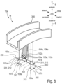
- the further embodiment of the surgical instrument 1a according to Fig. 8 differs from the embodiment according to Fig. 1 to 7 in the design of the fixing element 102a.
- This includes a bar spring 104a instead of the torsion spring 104.
- the bar spring 104a is tongue-shaped.
- several - more precisely three - positive locking sections 103a are present.
- the form-fitting sections 103a are designed as snap hooks 105a.
- Each of the form-fitting sections 103a forms an undercut 110a with respect to the anterior direction A.
- the surgical instrument system 10, 10a includes the surgical instrument 1, 1a and the femoral trial implant 200.
- the surgical instrument 1, 1a is detachably attached to the trial implant 200.
- the positioning pins 101, 101a and the receiving holes 201 are designed to complement each other.
- the positioning pins 101, 101a are at least partially inserted into the receiving holes 201 in the posterior direction P.
- the fixing element 102, 102a and the fixing section 203 are coordinated with one another to form the positive connection S.
- the surgical instrument 1, 1a is held on the trial implant 200 by means of the positive fit S.
- the positive fit S holds the surgical instrument 1, 1a in the anterior direction A on the trial implant 200.
- a positive fit can be formed between the bottoms 213 of the blind holes 212 and the first ends 107 of the positioning pins 101, which holds the surgical instrument 1, 1a in the posterior direction P holds on the trial implant 200.
- a positive connection can also be formed between the positioning pins 101 and the associated receiving bores 201, which holds the surgical instrument 100, 100a proximodistally and mediolaterally on the trial implant 200.
- the surgical instrument system 10, 10a includes several trial implants 200.
- the trial implants 200 differ in size.
- the different sized trial implants 200 are tailored to femur bones of different sizes.
- a suitable trial implant 200 can be selected.
- the two receiving bores 201 are arranged at a proximodistal distance 11 from a proximal outermost point DP of the respective trial implant 200.
- This point DP can be a so-called dwell point.
- the distance 11 is based on the central longitudinal axes of the receiving bores 201.
- the proximodistal distance 11 is the same for all of the trial implants 200, i.e. H. identical.
- the receiving holes 201 of each of the trial implants 200 are also arranged at a mediolateral distance 12 from one another.
- the mediolateral distance 12 is based, for example, on the central longitudinal axes of the receiving bores 201.
- the mediolateral distance 12 is the same for all trial implants 200, i.e. H. identical. In other words: Regardless of their size, all trial implants 200 of the surgical instrument system 10, 10a have receiving holes 201 with a uniform proximodistal distance 11 and a uniform mediolateral distance 12.
- the surgical instrument system 10, 10a can also include a guide device 300.
- the guide device 300 can be detachably connected to the fastening device 100.
- a further fastening device can also be releasably connected to the guide device 300, to which a tibial cut block can be fastened for guiding a resection cut on the proximal tibia.
- the guide device 300 By means of the guide device 300, the further fastening device can be aligned relative to the first fastening device 100, 100a.
- the detachable connection of the first fastening device 100, 100a with the guide device 300 can be realized by means of a plug connection 400.
- the guide device 300 can be designed in the shape of a circular arc, so that the fastening device 100, 100a is pivotally movable relative to the further fastening device. This allows the inclination of the tibia cutting block to be adjusted in a guide plane.
- the management plane is oriented sagittally and therefore extends anteroposteriorly and proximodistally.
- a pivot axis, about which the two fastening devices are pivotally guided relative to one another by means of the guide device intersects a mechanical tibial axis in the sagittal guide plane.
- the slope in question is also known as the posterior or anterior slope.
- slope - The adjustability of the inclination of the tibial cutting block - hereinafter referred to as slope - allows, on the one hand, an adjustment to preoperatively determined parameters. On the other hand, can an actually prevailing flexion or extension position of the leg can be taken into account and compensated for by the mobility of the guide device. This makes it possible to ensure that an adjustment of the slope does not simultaneously lead to an unwanted change in a proximodistal position of the tibial cutting block and thus a so-called tibial cutting height.
Landscapes
- Health & Medical Sciences (AREA)
- Orthopedic Medicine & Surgery (AREA)
- Transplantation (AREA)
- Heart & Thoracic Surgery (AREA)
- Cardiology (AREA)
- Oral & Maxillofacial Surgery (AREA)
- Engineering & Computer Science (AREA)
- Biomedical Technology (AREA)
- Vascular Medicine (AREA)
- Life Sciences & Earth Sciences (AREA)
- Animal Behavior & Ethology (AREA)
- General Health & Medical Sciences (AREA)
- Public Health (AREA)
- Veterinary Medicine (AREA)
- Physical Education & Sports Medicine (AREA)
- Prostheses (AREA)
Abstract
Description
- Die Erfindung betrifft ein chirurgisches Instrument zur Verwendung bei einer Kniegelenkersatzoperation. Die Erfindung betrifft außerdem ein femorales Probeimplantat zur Verwendung bei einer Kniegelenkersatzoperation. Ferner betrifft die Erfindung ein chirurgisches Instrumentensystem zur Verwendung bei einer Kniegelenkersatzoperation.
- Bei einer Kniegelenkersatzoperation (englisch: Total Knee Arthroplasty (TKA)) werden abgenutzte oder anderweitig durch Krankheit oder einen Unfall beeinträchtigte Gelenkflächen des Femurs oder/und der Tibia durch künstliche Gelenkflächen einer Kniegelenkprothese ersetzt. Solche Kniegelenkprothesen umfassen üblicherweise eine Femurkomponente und eine Tibiakomponente. Die Femurkomponente wird am distalen Ende des Femurs implantiert. Die Tibiakomponente wird am proximalen Ende der Tibia implantiert.
- Vor der Implantation der prothetischen Komponenten werden der distale Femur und die proximale Tibia reseziert. Hierfür bringt der Chirurg unterschiedliche Resektionsschnitte an und trennt Knochen- oder/und Knorpelmaterial von dem jeweiligen Knochen ab. Durch die Resektion wird der jeweilige Knochen in seiner Form an die aufzunehmende prothetische Komponente angepasst.
- Die Resektion kann auf der Grundlage unterschiedlicher Konzepte ausgeführt werden. Ein Konzept zielt darauf ab, die Spannungen der Bänder des Knies bei der Gelenkbewegung ausgeglichen zu halten. Hierdurch soll eine bessere Funktion der Kniegelenkprothese gewährleistet werden. Dieses Konzept wird allgemein als "gap balancing" bezeichnet. Bei anderen Konzepten entfernt der Chirurg mittels der Resektion eine bestimmte Menge an Knochen- oder/und Knorpelmaterial. Solche Konzepte werden allgemein als "measured resection" bezeichnet. Die Ausrichtung der Resektionsschnitte in Bezug auf die Anatomie des Patienten bestimmt die spätere Ausrichtung der implantierten Komponenten und folglich auch die Orientierung der prothetischen Gelenkachsen. Die Ausrichtung der Resektionsschnitte ist daher von besonderer Bedeutung.
- Bei der Ausrichtung der Resektionsschnitte werden in erster Linie drei Ansätze unterschieden: mechanisch, anatomisch und kinematisch. Bei der mechanischen Ausrichtung wird die proximale Tibia senkrecht zur Längsachse des Tibiaschafts reseziert. Die Resektion des distalen Femurs erfolgt entsprechend hieran angepasst. Erforderlichenfalls werden Bandentlastungen (englisch: ligament releases) durchgeführt. Bei der anatomischen Ausrichtung wird versucht, die Tibia in einem Varus-Winkel von 3° zu resezieren. Die Femurresektion und Bandentlastungen werden mit dem Ziel einer geraden Hüft-Knie-Knöchel-Achse des Beins durchgeführt. Ziel der kinematischen Ausrichtung (englisch: kinematic alignment, nachfolgend abgekürzt als KA) ist es, die künstlichen Gelenkflächen der prothetischen Komponenten auf dem Niveau der präarthritischen, defektfreien natürlichen Gelenkflächen zu implantieren.
- Bei einem KA erfolgt die Ausrichtung der Resektionsschnitte oftmals ausgehend von dem distalen Femur. Die Resektion der proximalen Tibia erfolgt hieran angepasst. Zum Zweck der zeitlich nacheinander erfolgenden Resektion von Femur und Tibia sind spezielle chirurgische Instrumente bekannt, die auch als tibiales Ausricht- oder/und Übertragungswerkzeug (tibial cut alignment guide) bezeichnet werden. Solche Instrumente erlauben eine Übertragung der Ausrichtung der femoralen Resektionsschnitte auf die Tibia. Die Übertragung erfolgt üblicherweise nach einer wenigstens distalen Resektion des Femurs, bei welcher die distalen Kondylen abgetrennt werden. Die Übertragung kann in Extension oder Flexion erfolgen. Bei einer Variante der KA wird zunächst der distale Femur vollständig präpariert (all femur first). Dabei werden die am distalen Femur vorzunehmenden Resektionsschnitte an der Anatomie des Patienten ausgerichtet und am distalen Femur angebracht. Anschließend wird ein femorales Probeimplantat an dem distalen Femur angebracht. Das bereits nach der Anatomie des Patienten ausgerichtete femorale Probeimplantat wird dann als Referenzkomponente herangezogen, deren Ausrichtung mittels des Übertragungswerkzeugs auf die proximale Tibia übertragen wird, um die daran vorzunehmenden Resektionsschnitte auszurichten und anzubringen. Es versteht sich, dass alternativ ein Vorgehen in umgekehrter Reihenfolge denkbar ist, also von der proximalen Tibia ausgehend.
- Besagte Übertragungswerkzeuge weisen üblicherweise eine Befestigungseinrichtung auf, die zur lösbaren Befestigung an einem femoralen Probeimplantat eingerichtet ist. Typischerweise ist die Befestigungseinrichtung formschlüssig lösbar an dem Probeimplantat befestigbar. Solche Probeimplantate sind oftmals dünnwandig ausgebildet. Für die Ausbildung des Formschlusses steht daher nur eine relativ geringe Materialstärke zur Verfügung. Die Ausbildung des Formschlusses und seine zuverlässige Aufrechterhaltung erweisen sich folglich als besonders herausfordernd. Infolge der oftmals geringen Materialstärke des Probeimplantats kann es zu elastischen oder/und plastischen Verformungen kommen. Diese können zu einem Lockern oder/und Lösen des Formschlusses führen. Zudem können Verkippbewegungen der Befestigungseinrichtung relativ zu dem Probeimplantat auftreten. Hierdurch kann die Ausrichtung des Übertragungswerkzeugs verfälscht werden.
- Aufgabe der Erfindung ist es, ein chirurgisches Instrument sowie ein femorales Probeimplantat und ein chirurgisches Instrumentensystem bereitzustellen, welche Vorteile gegenüber herkömmlichen chirurgischen Instrumenten sowie femoralen Probeimplantaten und chirurgischen Instrumentensystemen bieten. Insbesondere soll eine besonders verkippsichere Befestigung des chirurgischen Instruments an dem Probeimplantat ermöglicht werden.
- Diese Aufgabe wird durch das Bereitstellen eines chirurgischen Instruments mit den Merkmalen des Anspruchs 1, eines femoralen Probeimplantats mit den Merkmalen des Anspruchs 9 sowie eines chirurgischen Instrumentensystems mit den Merkmalen des Anspruchs 14 gelöst. Bevorzugte Ausführungsformen sind Gegenstand der abhängigen Patentansprüche.
- Das erfindungsgemäße chirurgische Instrument dient zur Verwendung bei einer Kniegelenkersatzoperation und weist auf: eine Befestigungseinrichtung, welche zur lösbaren Befestigung an einem an einem distalen Femur angebrachten femoralen Probeimplantat eingerichtet ist, wobei die Befestigungseinrichtung zwei mediolateral voneinander beabstandet angeordnete Positionierstifte aufweist, die zur Positionierung der Befestigungseinrichtung in zwei zu den Positionierstiften komplementären Aufnahmebohrungen des Probeimplantats in einer posterioren Richtung einsteckbar ausgebildet sind, wobei die Befestigungseinrichtung wenigstens ein Fixierelement zum formschlüssigen Fixieren der Befestigungseinrichtung an dem Probeimplantat in einer anterioren Richtung aufweist. Das Probeimplantat ist nicht Bestandteil des chirurgischen Instruments. Durch Zusammenwirken der Positionierstifte mit den Aufnahmebohrungen lässt sich das chirurgische Instrument mediolateral, anteroposterior und proximodistal in korrekter Ausrichtung relativ zum Probeimplantat positionieren. Mittels des Fixierelements lässt sich die Positionierung des chirurgischen Instruments formschlüssig fixieren. Das Fixierelement wirkt einem ungewollten Lösen der Steckverbindung entgegen. Im Speziellen wird einem anterioren Herausgleiten der Positionierstifte aus den Aufnahmebohrungen entgegengewirkt. Das Fixierelement sorgt in vorteilhafter Weise dafür, dass die Positionierstifte über eine ausreichende Tiefe in den Aufnahmebohrungen aufgenommen bleiben. Eine zwischen den Positionierstiften und den Aufnahmebohrungen auftretende Flächenpressung kann folglich geringgehalten werden. Entsprechend gering kann auch eine Verformung der Positionierstifte oder/und der Aufnahmebohrungen ausfallen, wenn zwischen der Befestigungseinrichtung und dem Probeimplantat ein verkippendes Drehmoment wirkt. Einem unerwünschten Verkippen des chirurgischen Instruments relativ zu dem Probeimplantat infolge wird somit besonders wirksam entgegengewirkt. Entsprechend erweist sich das chirurgische Instrument als besonders zuverlässig und robust in der Anwendung. Zudem ermöglicht es eine besonders präzise Übertragung der Ausrichtung des Probeimplantats auf eine proximale Tibia.
- Die in dieser Beschreibung verwendeten Lage- und Richtungsbezeichnungen beziehen sich auf den Körper eines Patienten, insbesondere dessen Femur, und sind insoweit gemäß ihrer üblichen anatomischen Bedeutung zu verstehen. Folglich bedeutet "anterior" vordere(r) oder vorne liegend, "posterior" hintere(r) oder hinten liegend, "medial" innere(r) oder innen liegend, "lateral" äußere(r) oder außen liegend, "proximal" zum Körperzentrum hin und "distal" vom Körperzentrum entfernt. Weiter bedeuten "proximodistal" entlang, vorzugsweise parallel zu, einer proximal-distal ausgerichteten Achse, "anteroposterior" entlang, vorzugsweise parallel zu, einer anterior-posterior ausgerichteten Achse und "mediolateral" entlang, vorzugsweise parallel zu, einer medial-lateral ausgerichteten Achse. Die besagten Achsen sind orthogonal zueinander ausgerichtet und können selbstverständlich in Bezug zu nicht mit der Anatomie des Patienten in Verbindung stehenden X-, Y- und Z-Achsen gesetzt werden. Beispielsweise kann die proximaldistale Achse alternativ als X-Achse bezeichnet werden. Die medial-laterale Achse kann als Y-Achse bezeichnet werden. Die anterior-posteriore Achse kann als Z-Achse bezeichnet werden. Zur verbesserten Veranschaulichung und der Einfachheit der Bezeichnungen wegen werden nachfolgend in erster Linie die besagten anatomischen Lage- und Richtungsbezeichnungen verwendet.
- In Ausgestaltung der Erfindung weist das Fixierelement wenigstens einen Formschlussabschnitt zur Ausbildung eines Formschlusses zwischen Befestigungseinrichtung und Probeimplantat auf. Der Formschlussabschnitt kann eine Nase, einen Haken, einen Stift, eine Schraube oder Ähnliches umfassen. Dies erlaubt eine besonders zuverlässige Fixierung des chirurgischen Instruments an dem femoralen Probeimplantat.
- In weiterer Ausgestaltung der Erfindung umfasst das Fixierelement wenigstens einen Schnapphaken. Ein solcher Schnapphaken kann beim Einführen der Positionierstifte in die komplementären Aufnahmebohrungen selbsttätig an dem Probeimplantat einrasten. Somit kann vorteilhaft auf eine gesonderte Verriegelungsmaßnahme zur Ausbildung des Formschlusses beim Montieren des chirurgischen Instruments an dem femoralen Probeimplantat verzichtet werden. Entsprechend erweist sich das chirurgische Instrument als besonders einfach in der Handhabung. Zudem hilft es eine Operationsdauer kurz zu halten.
- In weiterer Ausgestaltung der Erfindung ist das Fixierelement relativ zu den Positionierstiften zwischen einer Fixier- und einer Freigabeposition verstellbeweglich. In der Fixierposition kann der Formschluss ausgebildet sein. In der Freigabeposition kann der Formschluss gelöst sein. Vorzugsweise lässt sich das Fixierelement manuell zwischen seiner Freigabeposition und seiner Fixierposition bewegen. Somit kann der Formschluss durch Verstellen des Fixierelements in seine Freigabeposition erforderlichenfalls gelöst werden, um das chirurgische Instrument vom Probeimplantat zu trennen. Das Lösen des Formschlusses ist vorzugsweise rein manuell oder/und ohne eine Verwendung eines gesonderten Werkzeugs möglich.
- In weiterer Ausgestaltung der Erfindung umfasst die Befestigungseinrichtung wenigstens ein Federelement, insbesondere ein Torsions- oder Balkenfederelement, zum Erzeugen einer Federkraft, die das Fixierelement in Richtung seiner Fixierposition zwingt. Ein Verstellen des Fixierelements in seine Freigabeposition kann also entgegen und unter Überwindung der Federkraft erfolgen. Somit lässt sich besonders wirksam vermeiden, dass der Formschluss versehentlich gelöst wird. Außerdem kann das Fixierelement durch die Federkraft selbsttätig in seine Fixierposition verstellt und dort gehalten werden. Der Formschluss kann also selbsttätig ausgebildet werden, wenn die Positionierstifte in die Aufnahmebohrungen eingeführt werden. Eine gesonderte Betätigung des Fixierelements durch den Operateur ist in diesem Fall obsolet.
- In weiterer Ausgestaltung der Erfindung sind die Positionierstifte jeweils zwischen einem ersten und einem zweiten Ende anteroposterior längserstreckt, wobei ein jeweils an dem ersten Ende vorhandener erster Endabschnitt in einer zugehörigen der Aufnahmebohrungen des Probeimplantats unter Ausbildung einer Steckverbindung in posteriorer Richtung aufnehmbar ist. Derartige Positionierstifte sind, insbesondere mit ausreichender Präzision, besonders kostengünstig herstellbar.
- In weiterer Ausgestaltung der Erfindung bildet der Formschlussabschnitt eine Hinterschneidung bezüglich der anterioren Richtung aus. Die Hinterschneidung verhindert ein unbeabsichtigtes Trennen der Befestigungseinrichtung vom Probeimplantat in anteriorer Richtung. Dies erlaubt eine besonders zuverlässiges Fixieren der Befestigungseinrichtung.
- In weiterer Ausgestaltung der Erfindung liegen die ersten Enden posterior frei und die Hinterschneidung liegt anterior frei, so dass das Probeimplantat zwischen den ersten Enden einerseits und der Hinterschneidung andererseits anteroposterior positionierbar, insbesondere einspannbar, ist. Mit anderen Worten: die ersten Enden und die Hinterschneidung sind anteroposterior zueinander entgegengesetzt orientiert. Somit lässt sich vorteilhaft die Position der Befestigungseinrichtung sowohl anterior als auch posterior fixieren.
- Die Erfindung betrifft ferner ein femorales Probeimplantat zur Verwendung bei einer Kniegelenkersatzoperation. Es weist auf: eine Knochenkontaktfläche, die zur Kontaktierung eines distalen Femurs eingerichtet ist, zwei Aufnahmebohrungen, die jeweils zur Aufnahme eines Positionierstifts eines, insbesondere erfindungsgemäßen und der voranstehenden Beschreibung entsprechenden, chirurgischen Instruments eingerichtet sind, und einen Fixierabschnitt, welcher zur formschlüssigen Verbindung mit einem Fixierelement des chirurgischen Instruments eingerichtet ist. Die oben genannten Vorteile des erfindungsgemäßen chirurgischen Instruments übertragen sich mutatis mutandis auch auf das erfindungsgemäße femorale Probeimplantat.
- In Ausgestaltung der Erfindung ist die Knochenkontaktfläche an einer proximalen Rückseite eines Grundkörpers des Probeimplantats angeordnet und liegt einer distalen Vorderseite des Grundkörpers gegenüber, wobei der Grundkörper zwei mediolateral zueinander beabstandete und jeweils anteroposterior erstreckte Kondylenabschnitte aufweist, die an ihren anterioren Enden in einen Verbindungsabschnitt des Grundkörpers übergehen, wobei der Fixierabschnitt an einem posterioren Ende des Verbindungsabschnitts mediolateral zwischen den beiden Kondylenabschnitten angeordnet ist. Hieraus ergibt sich eine zentrale Anordnung des Fixierabschnitts. Der Fixierabschnitt kann dabei in einem Bereich angeordnet sein, in welchem vor der Resektion des Femurs die Kreuzbandhöhle (englisch: intercondylar notch) vorhanden war. Der so angeordnete Fixierabschnitt erlaubt eine zentrale Einleitung einer Haltekraft vom Fixierelement in das Probeimplantat. Dies sorgt für eine besonders stabile und verkippsichere lösbare Verbindung von Befestigungseinrichtung und Probeimplantat.
- In weiterer Ausgestaltung der Erfindung ist der Fixierabschnitt mediolateral zwischen den beiden Aufnahmebohrungen sowie - alternativ oder zusätzlich - proximodistal im Abstand zu den beiden Aufnahmebohrungen angeordnet. Die mediolaterale Anordnung sorgt für eine besonders gleichmäßige Einleitung von Befestigungskräften über das Formschlusselement und die Positionierstifte in das Probeimplantat. Der proximodistale Abstand zwischen dem Fixierelement und den Aufnahmebohrungen kann vorteilhaft als Hebel zum Abstützen von Drehmomenten zwischen Befestigungseinrichtung und Probeimplantat fungieren.
- In weiterer Ausgestaltung der Erfindung ist wenigstens eine, vorzugsweise jede, der Aufnahmebohrungen als Sackloch ausgebildet. Ein Boden der sacklochförmigen Aufnahmebohrungen bildet dabei vorteilhaft einen, insbesondere posterioren, Anschlag für die Positionierstifte. Entsprechend lässt sich eine posteriore Position des chirurgischen Instruments relativ zum Probeimplantat auf besonders einfache Weise und dauerhaft festlegen.
- Die Erfindung betrifft ferner ein chirurgisches Instrumentensystem zur Verwendung bei einer Kniegelenkersatzoperation, welches aufweist: ein erfindungsgemäßes chirurgisches Instrument gemäß der vorhergehenden Beschreibung, ein erfindungsgemäßes femorales Probeimplantat gemäß der vorhergehenden Beschreibung, wobei das chirurgische Instrument lösbar an dem Probeimplantat befestigt ist, wobei die Positionierstifte und die Aufnahmebohrungen komplementär zueinander ausgebildet und die Positionierstifte entlang der posterioren Richtung wenigstens teilweise in die Aufnahmebohrung gesteckt sind, wobei das Fixierelement und der Fixierabschnitt zum Ausbilden eines Formschlusses aufeinander abgestimmt sind und das chirurgische Instrument an dem Probeimplantat mittels des Formschlusses, insbesondere in anteriorer Richtung, fixiert ist. Die voranstehend aufgezeigten Vorteile des erfindungsgemäßen chirurgischen Instruments sowie des erfindungsgemäßen femoralen Probeimplantats übertragen sich mutatis mutandis auch auf das erfindungsgemäße chirurgische Instrumentensystem gemäß der Erfindung.
- In weiterer Ausgestaltung der Erfindung umfasst das chirurgische Instrumentensystem mehrere Probeimplantate unterschiedlicher Größen, wobei bei allen Probeimplantaten beide der Aufnahmebohrungen, insbesondere bezüglich ihrer Mittellängsachsen, in einem identischen proximodistalen Abstand zu einem proximal äußersten Punkt des jeweiligen Probeimplantats angeordnet sind, wobei die Aufnahmebohrungen jedes der Probeimplantate in einem identischen mediolateralen Abstand, insbesondere bezüglich der Mittellängsachsen, voneinander angeordnet sind. Gemeint ist damit ausdrücklich nicht, dass der proximodistale und der mediolaterale Abstand bei ein und demselben Probeimplantat betragsmäßig identisch sein müssen. Vielmehr ist den mehreren unterschiedlich großen Probeimplantaten größenunabhängig sowohl der proximodistale Abstand wie auch der mediolaterale Abstand gemein. Mit anderen Worten: Alle Probeimplantate des chirurgischen Instrumentensystems weisen einen einheitlichen proximalen Abstand und einen einheitlichen mediolateralen Abstand auf. Vorteilhaft lässt sich somit ein- und dasselbe chirurgische Instrument mit verschieden großen Probeimplantaten verwenden. Die Größen der Probeimplantate können abgestimmt sein auf verschieden groß ausgebildete oder gewachsene Femurknochen. Entsprechend lässt sich ein Probeimplantat bestimmter Größe aus den mehreren Probeimplantaten auswählen, das am besten auf eine gegebene Anatomie des Patienten passt. Unabhängig von der Größe des Probeimplantats lässt sich mittels des chirurgischen Instruments die Ausrichtung des Probeimplantats an der Anatomie des Patienten auf die Tibia übertragen. Insbesondere ergibt sich unabhängig von der gewählten Größe des Probeimplantats eine korrekte sog. Tibiaschnitthöhe. Der proximal äußerste Punkt kann auch als "Dwell-Point" bezeichnet werden.
- Weitere Vorteile und Merkmale der Erfindung ergeben sich aus den Ansprüchen sowie aus der nachfolgenden Beschreibung bevorzugter Ausführungsbeispiele der Erfindung, die anhand der Zeichnungen dargestellt sind.
- Es versteht sich, dass die voranstehend genannten und die nachstehend noch zu erläuternden Merkmale nicht nur in der jeweils angegebenen Kombination, sondern auch in anderen Kombinationen oder in Alleinstellung verwendbar sind, ohne den Rahmen der vorliegenden Erfindung zu verlassen.
- Fig. 1
- zeigt eine schematische Perspektivdarstellung einer Ausführungsform eines erfindungsgemäßen chirurgischen Instrumentensystems mit einem gemäß der Erfindung ausgeführten chirurgischen Instrument in einer intraoperativen Situation,
- Fig. 2
- ein Detail B des chirurgischen Instrumentensystems nach
Fig. 1 , - Fig. 3
- das chirurgische Instrumentensystem nach den
Fig. 1 und2 in einer schematischen Perspektivdarstellung aus einem anderen Blickwinkel, - Fig. 4
- eine schematische Vorderansicht des chirurgischen Instrumentensystems nach den
Fig. 1 bis 3 , - Fig. 5
- eine schematische Schnittdarstellung entlang einer Schnittlinie D-D nach
Fig. 4 , - Fig. 6
- ein Detail H der Darstellung nach
Fig. 5 , - Fig. 7
- eine schematische Schnittdarstellung entlang einer Schnittlinie G-G nach
Fig. 4 , - Fig. 8
- eine schematische Perspektivdarstellung einer weiteren Ausführungsform eines erfindungsgemäßen chirurgischen Instrumentensystems mit einem weiteren gemäß der Erfindung ausgeführten chirurgischen Instrument.
- Gemäß den
Fig. 1 und2 ist ein chirurgisches Instrument 1 zur Verwendung bei einer Kniegelenkersatzoperation vorgesehen. Das chirurgische Instrument 1 kann auch als Übertragungswerkzeug oder tibia transfer tool bezeichnet werden und dient einer referenzierten Positionierung eines Tibiaschnittblocks an einer proximalen Tibia. Tibiaschnittblock und Tibia sind in den Figuren nicht gezeigt. Als Referenz für die Position des Tibiaschnittblocks dient ein bereits an einem distalen Femur F positioniertes femorales Probeimplantat 200. Das femorale Probeimplantat 200 und der Tibiaschnittblock sind nicht Bestandteil des chirurgischen Instruments 1. Das Probeimplantat 200 und das chirurgische Instrument 1 sind Bestandteil eines chirurgischen Instrumentensystems 10. Das chirurgische Instrument 1 und das chirurgische Instrumentensystem 10 eignen sich insbesondere für Kniegelenkersatzoperationen, die dem sogenannten all femur first-Ansatz folgen. Gemäß diesem Ansatz werden zunächst sämtliche erforderliche femorale Resektionsschnitte angebracht. Nach Resektion des distalen Femurs F wird das femorale Probeimplantat 200 befestigt, welches dann als femorale Referenzkomponente für das chirurgische Instrument 1 fungieren kann. In denFig. 1 und2 ist das femorale Probeimplantat 200 an dem zuvor resezierten distalen Femur F befestigt. Mittels des chirurgischen Instruments 1 lässt sich eine bereits an der Anatomie des Patienten vorgenommene Ausrichtung des Probeimplantats 200 auf eine proximale Tibia transferieren, um dort in korrekter Ausrichtung wenigstens einen Resektionsschnitt vorzunehmen. - Das chirurgische Instrument 1 weist eine Befestigungseinrichtung 100 auf. Die Befestigungseinrichtung 100 ist zur lösbaren Befestigung an dem femoralen Probeimplantat 200 eingerichtet. Die Befestigungseinrichtung 100 umfasst zwei Positionierstifte 101. Die beiden Positionierstifte 101 sind mediolateral voneinander beabstandet angeordnet. Die Positionierstifte 101 sind zur Positionierung der Befestigungseinrichtung 100 in zwei Aufnahmebohrungen 201 des Probeimplantats 200 einsteckbar ausgebildet. Die Aufnahmebohrungen 201 sind komplementär zu den Positionierstiften 101 ausgebildet. Die Positionierstifte 101 sind in einer posterioren Richtung P in die Aufnahmebohrungen 201 einsteckbar ausgebildet. Mit anderen Worten: Die Positionierstifte 101 können entlang der posterioren Richtung P in die komplementären Aufnahmebohrungen 201 eingeführt oder eingeschoben werden.
- Die Befestigungseinrichtung 100 umfasst ferner wenigstens ein Fixierelement 102. Das Fixierelement 102 dient zum formschlüssigen Halten oder/und Fixieren der Befestigungseinrichtung 100 an dem Probeimplantat 200. Das Fixierelement 102 ist zum formschlüssigen Halten oder/und Fixieren der Befestigungseinrichtung 100 an dem Probeimplantat 200 in einer anterioren Richtung A eingerichtet. Das Fixierelement 102 weist wenigstens einen Formschlussabschnitt 103 auf. Der Formschlussabschnitt 103 dient zur Ausbildung eines Formschlusses S zwischen Befestigungseinrichtung 100 und Probeimplantat 200. Der Formschlussabschnitt 103 kann in Form einer Nase, eines Hakens, eines Stifts, einer Schraube oder Ähnlichem ausgebildet sein. Vorliegend umfasst das Fixierelement 102 einen Schnapphaken 105. Der Schnapphaken 105 rastet beim Einstecken der beiden Positionierstifte 101 in die Aufnahmebohrungen 201 selbsttätig an dem Probeimplantat 200 ein.
- Das Fixierelement 102 ist relativ zu den Positionierstiften 101 zwischen einer Fixier- und einer Freigabeposition verstellbeweglich. In der Fixierposition kann der Formschluss S ausgebildet sein. In der Freigabeposition kann der Formschluss S aufgehoben oder gelöst sein. In der in den
Fig. 1 und2 gezeigten intraoperativen Situation befindet sich das Fixierelement 102 in seiner Fixierposition. Dabei ist das chirurgische Instrument 1 mittels des Fixierelements 102 an dem Probeimplantat 200 fixiert. Durch Verstellen des Fixierelements 102 in seine Freigabeposition lässt sich das chirurgische Instrument 1 von dem Probeimplantat 200 in der anterioren Richtung A trennen. - Die Befestigungseinrichtung 100 weist außerdem wenigstens ein Federelement 106 auf. Bei dem Federelement 106 handelt es sich vorliegend um ein Torsionsfederelement 104. Das Federelement 106 dient zum Erzeugen einer Federkraft, die das Fixierelement 102 in Richtung seiner Fixierposition zwingt. Das Fixierelement 102 ist also mittels der Federkraft in seiner Fixierposition gehalten. Ein Verstellen des Fixierelements 102 in seine Freigabeposition erfolgt unter Überwindung der Federkraft. Infolge der Federkraft kann das Fixierelement 102 beim Einstecken der Positionierstifte 101 selbsttätig an dem Probeimplantat 200 formschlüssig einrasten. Mit anderen Worten: Die Federkraft bewirkt vorliegend, dass das Fixierelement 102 beim Einstecken der Positionierstifte 101 selbsttätig an dem Probeimplantat 200 einrastet.
- Die Positionierstifte 101 sind jeweils zwischen einem ersten und einem zweiten Ende 107, 108 anteroposterior längserstreckt. Dabei ist an dem ersten Ende 107 ein erster Endabschnitt 109 vorhanden. Der erste Endabschnitt 109 ist in einer zugehörigen der Aufnahmebohrungen 201 des Probeimplantats 200 unter Ausbildung einer Steckverbindung V in posteriorer Richtung P aufnehmbar. Wenigstens einer der Positionierstifte 101 und seine zugehörige Aufnahmebohrung 201 können in der Art einer engen Spielpassung oder einer Übergangspassung aufeinander abgestimmt sein. Sind einer der Positionierstifte 101 und seine zugehörige Aufnahmebohrung 201 passgenau aufeinander abgestimmt, können der jeweils andere Positionierstift 101 und seine zugehörige Aufnahmebohrung 201 ein mediolaterales Spiel aufweisen. Hierzu kann die betreffende Aufnahmebohrung 201 zur Erzeugung des mediolateralen Spiels langlochartig ausgebildet sein. Vorliegend weisen die Positionierstifte 201 wenigstens im Bereich ihres ersten Endabschnitts 109 einen kreisförmigen Querschnitt auf. Es versteht sich, dass alternativ auch andere Querschnittsformen denkbar sind, beispielsweise in Form eines Ovals oder eines Rechtecks oder eines anderen Vielecks.
- Der Formschlussabschnitt 103 bildet vorliegend bezüglich der anterioren Richtung A eine Hinterschneidung 110 aus. Dabei liegen die ersten Enden 107 posterior frei. Die Hinterschneidung 110 liegt anterior frei. Die ersten Enden 107 und die Hinterschneidung 110 sind anteroposterior zueinander entgegengesetzt orientiert. Folglich ist das Probeimplantat 200 zwischen den ersten Enden 107 einerseits und der Hinterschneidung 110 andererseits anteroposterior positionierbar. Vorliegend ist das Probeimplantat 200 zwischen den ersten Enden 107 und der Hinterschneidung 110 eingespannt. In der Einspannung kann die Hinterschneidung 110 ein Widerlager für die Positionierstifte 101 ausbilden.
- Die
Fig. 1 bis 8 zeigen ferner eine Ausführungsform eines erfindungsgemäßen femoralen Probeimplantats 200. Das femorale Probeimplantat 200 ist zur Verwendung bei einer Kniegelenkersatzoperation vorgesehen. Es weist eine Knochenkontaktfläche 202 auf. Die Knochenkontaktfläche 202 ist zur Kontaktierung des distalen Femurs F eingerichtet. Ferner umfasst das femorale Probeimplantat 200 die beiden Aufnahmebohrungen 201. Diese sind jeweils zur Aufnahme eines der Positionierstifte 101 des chirurgischen Instruments 1 eingerichtet. Das femorale Probeimplantat 200 umfasst außerdem einen Fixierabschnitt 203. Der Fixierabschnitt 203 ist zur formschlüssigen Verbindung mit dem Fixierelement 102 des chirurgischen Instruments 1 eingerichtet. Vorliegend weist das femorale Probeimplantat 200 einen, insbesondere klauenförmigen, Grundkörper 205 auf. Die Knochenkontaktfläche 202 ist an einer proximalen Rückseite 204 des Grundkörpers 205 angeordnet. Die proximale Rückseite 204 liegt einer distalen Vorderseite 206 des Grundkörpers 205 gegenüber. Der Grundkörper 205 umfasst zwei mediolateral zueinander beabstandete Kondylenabschnitte 207. Die beiden Kondylenabschnitte 207 sind jeweils anteroposterior erstreckt. Die Kondylenabschnitte 207 gehen an ihren anterioren Enden 202 in einen Verbindungsabschnitt 209 des Grundkörpers 205 über. Die Kondylenabschnitte 207 sind also mittels des Verbindungsabschnitts 209 miteinander verbunden. Dabei ist der Fixierabschnitt 203 an einem posterioren Ende 210 des Verbindungsabschnitts 209 angeordnet. Der Fixierabschnitt 203 befindet sich mediolateral zwischen den beiden Kondylenabschnitten 207. Der Fixierabschnitt 203 befindet sich vorliegend mediolateral zwischen den beiden Aufnahmebohrungen 201. Jeweils eine der Aufnahmebohrungen 201 kann im Bereich eines der Kondylenabschnitte 207 vorhanden sein. Alternativ oder zusätzlich ist der Fixierabschnitt 203 proximodistal im Abstand zu den beiden Aufnahmebohrungen 201 angeordnet. Vorliegend ist der Fixierabschnitt 203 sowohl mediolateral zwischen den beiden Aufnahmebohrungen 201 als auch proximodistal im Abstand zu den beiden Aufnahmebohrungen 201 angeordnet. Der Fixierabschnitt 203 bildet eine Hinterschneidung 211 bezüglich einer posterioren Richtung P aus. Die Hinterschneidung 110 des Fixierelements 102 ist also komplementär ausgebildet zur Hinterschneidung 211 des Fixierabschnitts 203. - Wenigstens eine der Aufnahmebohrungen 201 ist vorliegend als Sackloch 212 ausgebildet. Vorliegend sind beide der Aufnahmebohrungen 201 jeweils als Sackloch 212 ausgebildet. Ein Boden 213 des Sacklochs 212 fungiert als posteriorer Anschlag für die Positionierstifte 101. Entsprechend legt der Boden 213 zusammen mit den ersten Enden 107 der Positionierstifte 101 eine anteroposteriore Position des chirurgischen Instruments 1 relativ zum Probeimplantat 200 fest.
- Die weitere Ausführungsform des chirurgischen Instruments 1a gemäß
Fig. 8 unterscheidet sich von der Ausführungsform gemäß denFig. 1 bis 7 in der Ausgestaltung des Fixierelements 102a. Dieses umfasst statt der Torsionsfeder 104 eine Balkenfeder 104a. Die Balkenfeder 104a ist zungenförmig ausgebildet. Ferner sind gemäßFig. 8 mehrere - genauer drei - Formschlussabschnitte 103a vorhanden. Die Formschlussabschnitte 103a sind als Schnapphaken 105a ausgebildet. Jeder der Formschlussabschnitte 103a bildet eine Hinterschneidung 110a bezüglich der anterioren Richtung A aus. Mittels der Formschlussabschnitte 103a lassen sich drei Raststellungen des chirurgischen Instruments 1a festlegen, in welchen die Befestigungseinrichtung 100a am Probeimplantat 200 anteroposterior einrasten kann. Im Übrigen wird für die Ausführungsform gemäßFig. 8 auf die vorangehende Beschreibung der Ausführungsform gemäß denFig. 1 bis 7 verwiesen, wobei die entsprechenden Bezugszeichen in derFig. 8 um den Kleinbuchstaben a ergänzt sind. - Wie bereits angesprochen, umfasst das chirurgische Instrumentensystem 10, 10a das chirurgisches Instrument 1, 1a sowie das femorale Probeimplantat 200. Das chirurgische Instrument 1, 1a ist lösbar an dem Probeimplantat 200 befestigt. Die Positionierstifte 101, 101a und die Aufnahmebohrungen 201 sind komplementär zueinander ausgebildet. Die Positionierstifte 101, 101a sind in der posterioren Richtung P wenigstens teilweise in die Aufnahmebohrungen 201 eingesteckt. Dabei sind das Fixierelement 102, 102a und der Fixierabschnitt 203 zum Ausbilden des Formschlusses S aufeinander abgestimmt. Das chirurgische Instrument 1, 1a ist an dem Probeimplantat 200 mittels des Formschlusses S gehalten. Der Formschluss S hält das chirurgische Instrument 1, 1a in anteriorer Richtung A an dem Probeimplantat 200. Zwischen den Böden 213 der Sacklochbohrungen 212 und den ersten Enden 107 der Positionierstifte 101 kann ein Formschluss ausgebildet sein, der das chirurgische Instrument 1, 1a in posteriorer Richtung P an dem Probeimplantat 200 hält. Zwischen den Positionierstiften 101 und den zugehörigen Aufnahmebohrungen 201 kann außerdem ein Formschluss ausgebildet sein, der das chirurgische Instrument 100, 100a proximodistal und mediolateral an dem Probeimplantat 200 hält.
- Das chirurgische Instrumentensystem 10, 10a umfasst mehrere Probeimplantate 200. Die Probeimplantate 200 unterscheiden sich hinsichtlich ihrer Größe. Die verschieden großen Probeimplantate 200 sind auf Femurknochen unterschiedlicher Größe abgestimmt. Je nach Anatomie des behandelten Patienten lässt sich also ein geeignetes Probeimplantat 200 auswählen. Bei allen Probeimplantaten 200 sind die beiden Aufnahmebohrungen 201 in einem proximodistalen Abstand 11 zu einem proximal äußersten Punkt DP des jeweiligen Probeimplantats 200 angeordnet. Bei diesem Punkt DP kann es sich um einen sogenannten Dwell-Point handeln. Der Abstand 11 ist vorliegend auf die Mittellängsachsen der Aufnahmebohrungen 201 bezogen. Der proximodistale Abstand 11 ist bei allen der Probeimplantate 200 gleich groß, d. h. identisch. Die Aufnahmebohrungen 201 jedes der Probeimplantate 200 sind ferner in einem mediolateralen Abstand 12 voneinander angeordnet. Der mediolaterale Abstand 12 ist beispielsweise auf die Mittellängsachsen der Aufnahmebohrungen 201 bezogen. Der mediolaterale Abstand 12 ist für alle Probeimplantate 200 gleich groß, d. h. identisch. Mit anderen Worten: Unabhängig von ihrer Größe haben alle Probeimplantate 200 des chirurgischen Instrumentensystems 10, 10a Aufnahmebohrungen 201 mit einheitlichem proximodistalem Abstand 11 und einheitlichem mediolateralem Abstand 12.
- Das chirurgische Instrumentensystem 10, 10a kann außerdem eine Führungseinrichtung 300 umfassen. Die Führungseinrichtung 300 kann lösbar mit der Befestigungseinrichtung 100 verbunden sein. Mit der Führungseinrichtung 300 kann ferner eine weitere Befestigungseinrichtung lösbar verbunden sein, an welcher ein Tibiaschnittblock zur Führung eines Resektionsschnitts an der proximalen Tibia befestigbar ist. Mittels der Führungseinrichtung 300 kann die weitere Befestigungseinrichtung relativ zur ersten Befestigungseinrichtung 100, 100a ausgerichtet werden. Die lösbare Verbindung der ersten Befestigungseinrichtung 100, 100a mit der Führungseinrichtung 300 kann mittels einer Steckverbindung 400 realisiert sein.
- Die Führungseinrichtung 300 kann kreisbogenförmig ausgebildet sein, so dass die Befestigungseinrichtung 100, 100a relativ zur weiteren Befestigungseinrichtung geführt schwenkbeweglich ist. Hierdurch kann die Neigung des Tibiaschnittblocks in einer Führungsebene eingestellt werden. Die Führungsebene ist sagittal ausgerichtet und folglich anteroposterior sowie proximodistal erstreckt. Vorzugsweise schneidet eine Schwenkachse, um welche die beiden Befestigungseinrichtungen relativ zueinander mittels der Führungseinrichtung schwenkbeweglich geführt sind, eine mechanische Tibiaachse in der sagittalen Führungsebene. Die besagte Neigung wird auch als posteriorer oder anteriorer Slope bezeichnet. Die Einstellbarkeit der Neigung des Tibiaschnittblocks - nachfolgend kurz Slope - erlaubt zum einen eine Anpassung an präoperativ festgelegte Parameter. Zum anderen kann eine tatsächlich vorherrschende Flexions- oder Extensionsstellung des Beins durch die Beweglichkeit der Führungseinrichtung berücksichtigt und ausgeglichen werden. Hierdurch lässt sich sicherstellen, dass eine Einstellung des Slopes nicht gleichzeitig zu einer ungewollten Veränderung einer proximodistalen Position des Tibiaschnittblocks und damit einer sogenannten Tibiaschnitthöhe führt.
Claims (15)
- Chirurgisches Instrument (1, 1a) zur Verwendung bei einer Kniegelenkersatzoperation, aufweisendeine Befestigungseinrichtung (100, 100a), welche zur lösbaren Befestigung an einem an einem distalen Femur (F) angebrachten femoralen Probeimplantat (200) eingerichtet ist,wobei die Befestigungseinrichtung (100, 100a) zwei mediolateral voneinander beabstandet angeordnete Positionierstifte (101, 101a) aufweist, die zur Positionierung der Befestigungseinrichtung (100, 100a) in zwei zu den Positionierstiften (101, 101a) komplementären Aufnahmebohrungen (201, 201a) des Probeimplantats (200, 200a) in einer posterioren Richtung (P) einsteckbar ausgebildet sind,wobei die Befestigungseinrichtung (100, 100a) wenigstens ein Fixierelement (102, 102a) zum formschlüssigen Fixieren der Befestigungseinrichtung (100, 100a) an dem Probeimplantat (200) in einer anterioren Richtung (A) aufweist.
- Chirurgisches Instrument (1) nach Anspruch 1, dadurch gekennzeichnet, dass das Fixierelement (102, 102a) wenigstens einen Formschlussabschnitt (103, 103a) zur Ausbildung eines Formschlusses (S) zwischen der Befestigungseinrichtung (100, 101a) und dem Probeimplantat (200) aufweist.
- Chirurgisches Instrument (1, 1a) nach Anspruch 1 oder 2, dadurch gekennzeichnet, dass das Fixierelement (102, 102a) wenigstens einen Schnapphaken (105, 105a) umfasst.
- Chirurgisches Instrument (1, 1a) nach einem der vorhergehenden Ansprüche, dadurch gekennzeichnet, dass das Fixierelement (102, 102a) relativ zu den Positionierstiften (101, 101a) zwischen einer Fixier- und einer Freigabeposition verstellbeweglich ist.
- Chirurgisches Instrument (1, 1a) nach Anspruch 4, dadurch gekennzeichnet, dass die Befestigungseinrichtung (100, 100a) wenigstens ein Federelement (106, 106a), insbesondere ein Torsions- oder Balkenfederelement (104, 104a), zum Erzeugen einer Federkraft umfasst, die das Fixierelement (102, 102a) in Richtung seiner Fixierposition zwingt.
- Chirurgisches Instrument (1, 1a) nach einem der vorhergehenden Ansprüche, dadurch gekennzeichnet, dass die Positionierstifte (101, 101a) jeweils zwischen einem ersten und einem zweiten Ende (107, 107a, 108, 108a) anteroposterior längserstreckt sind, wobei ein jeweils am ersten Ende (107, 107a) vorhandener erster Endabschnitt (109, 109a) in einer zugehörigen der Aufnahmebohrungen (201) des Probeimplantats (200) unter Ausbildung einer Steckverbindung (V) in posteriorer Richtung (P) aufnehmbar ist.
- Chirurgisches Instrument (1, 1a) nach Anspruch 6, bei Rückbezug auf Anspruch 2, dadurch gekennzeichnet, dass der Formschlussabschnitt (103, 103a) eine Hinterschneidung (110, 110a) bezüglich der anterioren Richtung (A) ausbildet.
- Chirurgisches Instrument (1, 1a) nach Anspruch 7, dadurch gekennzeichnet, dass die ersten Enden (107, 107a) posterior freiliegen und die Hinterschneidung (110, 110a) anterior freiliegt, so dass das Probeimplantat (200) zwischen den ersten Enden (107, 107a) einerseits und der Hinterschneidung (110, 110a) andererseits anteroposterior positionierbar, insbesondere einspannbar, ist.
- Femorales Probeimplantat (200) zur Verwendung bei einer Kniegelenkersatzoperation, aufweisendeine Knochenkontaktfläche (202), die zur Kontaktierung eines distalen Femurs (F) eingerichtet ist,zwei Aufnahmebohrungen (201), die jeweils zur Aufnahme eines Positionierstifts (101, 101a) eines chirurgischen Instruments (1, 1a), insbesondere nach einem der vorhergehenden Ansprüche, eingerichtet sind,und einen Fixierabschnitt (203), welcher zur formschlüssigen Verbindung mit einem Fixierelement (102, 102a) des chirurgischen Instruments (1, 1a) eingerichtet ist.
- Femorales Probeimplantat (200) nach Anspruch 9, dadurch gekennzeichnet, dass die Knochenkontaktfläche (202) an einer proximalen Rückseite (204) eines Grundkörpers (205) des Probeimplantats (200) angeordnet ist und einer distalen Vorderseite (206) des Grundkörpers (205) gegenüberliegt, wobei der Grundkörper (205) zwei mediolateral zueinander beabstandete und jeweils anteroposterior erstreckte Kondylenabschnitte (207) aufweist, die an ihren anterioren Enden (202) in einen Verbindungsabschnitt (209) des Grundkörpers (205) übergehen, wobei der Fixierabschnitt (203) an einem posterioren Ende (210) des Verbindungsabschnitts (209) mediolateral zwischen den beiden Kondylenabschnitten (207) angeordnet ist.
- Femorales Probeimplantat (200) nach Anspruch 9 oder 10, dadurch gekennzeichnet, der Fixierabschnitt (203) mediolateral zwischen den beiden Aufnahmebohrungen (201) oder/und proximodistal im Abstand zu den beiden Aufnahmebohrungen (201) angeordnet ist.
- Femorales Probeimplantat (200) nach einem der Ansprüche 9 bis 11, dadurch gekennzeichnet, dass der Fixierabschnitt (203) eine Hinterschneidung (211) bezüglich einer posterioren Richtung (P) bildet.
- Femorales Probeimplantat (200) nach einem der Ansprüche 9 bis 12, dadurch gekennzeichnet, dass wenigstens eine, vorzugsweise jede, der Aufnahmebohrungen (201) als Sackloch (212) ausgebildet ist.
- Chirurgisches Instrumentensystem (10, 10a) zur Verwendung bei einer Kniegelenkersatzoperation, aufweisendein chirurgisches Instrument (1, 1a) nach einem der Ansprüche 1 bis 8,ein femorales Probeimplantat (200) nach einem der Ansprüche 9 bis 13, wobei das chirurgische Instrument (1, 1a) lösbar an dem Probeimplantat (200) befestigt ist,wobei die Positionierstifte (101, 101a) und die Aufnahmebohrungen (201) komplementär zueinander ausgebildet und die Positionierstifte (101, 101a) entlang der posterioren Richtung (P) wenigstens teilweise in die Aufnahmebohrungen (201) gesteckt sind,wobei das Fixierelement (102, 102a) und der Fixierabschnitt (203) zum Ausbilden eines Formschlusses (S) aufeinander abgestimmt sind und das chirurgische Instrument (1, 1a) an dem Probeimplantat (200) mittels des Formschlusses (S), insbesondere in anteriorer Richtung (A), fixiert ist.
- Chirurgisches Instrumentensystem (10, 10a) nach Anspruch 14, dadurch gekennzeichnet, dass mehrere Probeimplantate (200) unterschiedlicher Größen vorhanden sind, wobei bei allen Probeimplantaten (200) beide der Aufnahmebohrungen (201), insbesondere bezüglich ihrer Mittellängsachsen, in einem identischen proximodistalen Abstand (11) zu einem proximal äußersten Punkt (DP) des jeweiligen Probeimplantats (200) angeordnet sind, wobei die Aufnahmebohrungen (201) jedes der Probeimplantate (200) in einem identischen mediolateralen Abstand (12), insbesondere bezüglich der Mittellängsachsen, voneinander angeordnet sind.
Applications Claiming Priority (1)
| Application Number | Priority Date | Filing Date | Title |
|---|---|---|---|
| DE102022207577.3A DE102022207577A1 (de) | 2022-07-25 | 2022-07-25 | Chirurgisches Instrument, femorales Probeimplantat und chirurgisches Instrumentensystem |
Publications (2)
| Publication Number | Publication Date |
|---|---|
| EP4311525A1 true EP4311525A1 (de) | 2024-01-31 |
| EP4311525B1 EP4311525B1 (de) | 2025-09-03 |
Family
ID=87196495
Family Applications (1)
| Application Number | Title | Priority Date | Filing Date |
|---|---|---|---|
| EP23184058.8A Active EP4311525B1 (de) | 2022-07-25 | 2023-07-07 | Chirurgisches instrument, femorales probeimplantat und chirurgisches instrumentensystem |
Country Status (4)
| Country | Link |
|---|---|
| US (1) | US20240024131A1 (de) |
| EP (1) | EP4311525B1 (de) |
| JP (1) | JP2024015978A (de) |
| DE (1) | DE102022207577A1 (de) |
Families Citing this family (1)
| Publication number | Priority date | Publication date | Assignee | Title |
|---|---|---|---|---|
| DE102022207575A1 (de) * | 2022-07-25 | 2024-01-25 | Aesculap Ag | Chirurgisches Instrument |
Citations (5)
| Publication number | Priority date | Publication date | Assignee | Title |
|---|---|---|---|---|
| WO2012078498A1 (en) * | 2010-12-07 | 2012-06-14 | Zimmer, Inc. | Prosthetic inserter |
| US20190150948A1 (en) * | 2017-11-21 | 2019-05-23 | Smith & Nephew, Inc. | Femoral notch preparation guide |
| US20200113710A1 (en) * | 2018-10-15 | 2020-04-16 | Howmedica Osteonics Corp. | Patellofemoral Trial Extractor |
| CN114271894A (zh) * | 2021-11-30 | 2022-04-05 | 北京纳通医疗科技控股有限公司 | 手术器械 |
| WO2022090312A1 (en) * | 2020-10-27 | 2022-05-05 | Depuy Ireland Unlimited Company | Orthopaedic surgical instrument systems and associated methods of use |
Family Cites Families (1)
| Publication number | Priority date | Publication date | Assignee | Title |
|---|---|---|---|---|
| GB201522529D0 (en) | 2015-12-21 | 2016-02-03 | Smith & Nephew Orthopaedics Ag | Femoral prosthesis preparation |
-
2022
- 2022-07-25 DE DE102022207577.3A patent/DE102022207577A1/de active Pending
-
2023
- 2023-07-03 JP JP2023109500A patent/JP2024015978A/ja active Pending
- 2023-07-06 US US18/347,900 patent/US20240024131A1/en active Pending
- 2023-07-07 EP EP23184058.8A patent/EP4311525B1/de active Active
Patent Citations (5)
| Publication number | Priority date | Publication date | Assignee | Title |
|---|---|---|---|---|
| WO2012078498A1 (en) * | 2010-12-07 | 2012-06-14 | Zimmer, Inc. | Prosthetic inserter |
| US20190150948A1 (en) * | 2017-11-21 | 2019-05-23 | Smith & Nephew, Inc. | Femoral notch preparation guide |
| US20200113710A1 (en) * | 2018-10-15 | 2020-04-16 | Howmedica Osteonics Corp. | Patellofemoral Trial Extractor |
| WO2022090312A1 (en) * | 2020-10-27 | 2022-05-05 | Depuy Ireland Unlimited Company | Orthopaedic surgical instrument systems and associated methods of use |
| CN114271894A (zh) * | 2021-11-30 | 2022-04-05 | 北京纳通医疗科技控股有限公司 | 手术器械 |
Also Published As
| Publication number | Publication date |
|---|---|
| EP4311525B1 (de) | 2025-09-03 |
| DE102022207577A1 (de) | 2024-01-25 |
| JP2024015978A (ja) | 2024-02-06 |
| US20240024131A1 (en) | 2024-01-25 |
Similar Documents
| Publication | Publication Date | Title |
|---|---|---|
| EP0928172B1 (de) | Stiellose kniegelenkendoprothese | |
| DE69130391T2 (de) | Fraese zur resektion von knochen | |
| DE60224470T2 (de) | Hüftimplantataufbau | |
| DE69834363T2 (de) | Modulare Ausrüstung zur Vorbereitung eines Knochens und zur Prüfreduzierung orthopädischer Implantate | |
| DE60126527T2 (de) | Modulare Gelenkprothese | |
| DE60307212T2 (de) | Modulares Knieprothesensystem mit Zwischenelement für Oberschenkelschaft | |
| DE69434321T2 (de) | Fräsausrüstung zur Verwendung bei einer totalen Kniegelenkrekonstruktion | |
| DE102012201970B4 (de) | Verfahren und Vorrichtung zur Durchführung einer Arthroplastik | |
| EP1335684A2 (de) | Kniegelenk-endoprothese-system | |
| DE602004002749T2 (de) | Implantatsysteme mit Befestigungselement zur Befestigung an einer Artikulationsoberfläche von einem orthopädischen Gelenk | |
| EP4245229B1 (de) | Chirurgisches instrument | |
| EP4311506A2 (de) | Chirurgisches instrument und chirurgisches instrumentensystem | |
| EP4282346B1 (de) | Chirurgisches instrument | |
| EP4311525B1 (de) | Chirurgisches instrument, femorales probeimplantat und chirurgisches instrumentensystem | |
| EP4311507B1 (de) | Chirurgisches instrument | |
| EP4285844A1 (de) | Chirurgisches instrument | |
| EP4344681A1 (de) | Modulares instrumentensystem zur verwendung bei einer kniegelenkersatzoperation | |
| EP4282347B1 (de) | Chirurgisches instrumentensystem | |
| EP4282348B1 (de) | Chirurgisches instrument | |
| EP4311526A1 (de) | Femorales probekondylenimplantat | |
| EP4285845A1 (de) | Chirurgisches instrument | |
| EP4295787B1 (de) | Chirurgische vorrichtung | |
| EP4311505A1 (de) | Chirurgisches instrument | |
| DE19728636C1 (de) | Stiellose Kniegelenksendoprothese | |
| EP4454617A1 (de) | Tibiales probeimplantat |
Legal Events
| Date | Code | Title | Description |
|---|---|---|---|
| PUAI | Public reference made under article 153(3) epc to a published international application that has entered the european phase |
Free format text: ORIGINAL CODE: 0009012 |
|
| STAA | Information on the status of an ep patent application or granted ep patent |
Free format text: STATUS: THE APPLICATION HAS BEEN PUBLISHED |
|
| AK | Designated contracting states |
Kind code of ref document: A1 Designated state(s): AL AT BE BG CH CY CZ DE DK EE ES FI FR GB GR HR HU IE IS IT LI LT LU LV MC ME MK MT NL NO PL PT RO RS SE SI SK SM TR |
|
| STAA | Information on the status of an ep patent application or granted ep patent |
Free format text: STATUS: REQUEST FOR EXAMINATION WAS MADE |
|
| 17P | Request for examination filed |
Effective date: 20240724 |
|
| RBV | Designated contracting states (corrected) |
Designated state(s): AL AT BE BG CH CY CZ DE DK EE ES FI FR GB GR HR HU IE IS IT LI LT LU LV MC ME MK MT NL NO PL PT RO RS SE SI SK SM TR |
|
| GRAP | Despatch of communication of intention to grant a patent |
Free format text: ORIGINAL CODE: EPIDOSNIGR1 |
|
| STAA | Information on the status of an ep patent application or granted ep patent |
Free format text: STATUS: GRANT OF PATENT IS INTENDED |
|
| RIC1 | Information provided on ipc code assigned before grant |
Ipc: A61F 2/30 20060101ALN20250502BHEP Ipc: A61F 2/38 20060101ALI20250502BHEP Ipc: A61F 2/46 20060101AFI20250502BHEP |
|
| INTG | Intention to grant announced |
Effective date: 20250516 |
|
| GRAS | Grant fee paid |
Free format text: ORIGINAL CODE: EPIDOSNIGR3 |
|
| GRAA | (expected) grant |
Free format text: ORIGINAL CODE: 0009210 |
|
| STAA | Information on the status of an ep patent application or granted ep patent |
Free format text: STATUS: THE PATENT HAS BEEN GRANTED |
|
| AK | Designated contracting states |
Kind code of ref document: B1 Designated state(s): AL AT BE BG CH CY CZ DE DK EE ES FI FR GB GR HR HU IE IS IT LI LT LU LV MC ME MK MT NL NO PL PT RO RS SE SI SK SM TR |
|
| REG | Reference to a national code |
Ref country code: CH Ref legal event code: EP |
|
| REG | Reference to a national code |
Ref country code: DE Ref legal event code: R096 Ref document number: 502023001709 Country of ref document: DE |
|
| REG | Reference to a national code |
Ref country code: IE Ref legal event code: FG4D Free format text: LANGUAGE OF EP DOCUMENT: GERMAN |
|
| REG | Reference to a national code |
Ref country code: NL Ref legal event code: MP Effective date: 20250903 |
|
| PG25 | Lapsed in a contracting state [announced via postgrant information from national office to epo] |
Ref country code: NO Free format text: LAPSE BECAUSE OF FAILURE TO SUBMIT A TRANSLATION OF THE DESCRIPTION OR TO PAY THE FEE WITHIN THE PRESCRIBED TIME-LIMIT Effective date: 20251203 |
|
| REG | Reference to a national code |
Ref country code: LT Ref legal event code: MG9D |
|
| PG25 | Lapsed in a contracting state [announced via postgrant information from national office to epo] |
Ref country code: FI Free format text: LAPSE BECAUSE OF FAILURE TO SUBMIT A TRANSLATION OF THE DESCRIPTION OR TO PAY THE FEE WITHIN THE PRESCRIBED TIME-LIMIT Effective date: 20250903 |
|
| PG25 | Lapsed in a contracting state [announced via postgrant information from national office to epo] |
Ref country code: HR Free format text: LAPSE BECAUSE OF FAILURE TO SUBMIT A TRANSLATION OF THE DESCRIPTION OR TO PAY THE FEE WITHIN THE PRESCRIBED TIME-LIMIT Effective date: 20250903 |
|
| PG25 | Lapsed in a contracting state [announced via postgrant information from national office to epo] |
Ref country code: GR Free format text: LAPSE BECAUSE OF FAILURE TO SUBMIT A TRANSLATION OF THE DESCRIPTION OR TO PAY THE FEE WITHIN THE PRESCRIBED TIME-LIMIT Effective date: 20251204 |
|
| PG25 | Lapsed in a contracting state [announced via postgrant information from national office to epo] |
Ref country code: SE Free format text: LAPSE BECAUSE OF FAILURE TO SUBMIT A TRANSLATION OF THE DESCRIPTION OR TO PAY THE FEE WITHIN THE PRESCRIBED TIME-LIMIT Effective date: 20250903 |
|
| PG25 | Lapsed in a contracting state [announced via postgrant information from national office to epo] |
Ref country code: LV Free format text: LAPSE BECAUSE OF FAILURE TO SUBMIT A TRANSLATION OF THE DESCRIPTION OR TO PAY THE FEE WITHIN THE PRESCRIBED TIME-LIMIT Effective date: 20250903 |
|
| PG25 | Lapsed in a contracting state [announced via postgrant information from national office to epo] |
Ref country code: PL Free format text: LAPSE BECAUSE OF FAILURE TO SUBMIT A TRANSLATION OF THE DESCRIPTION OR TO PAY THE FEE WITHIN THE PRESCRIBED TIME-LIMIT Effective date: 20250903 Ref country code: BG Free format text: LAPSE BECAUSE OF FAILURE TO SUBMIT A TRANSLATION OF THE DESCRIPTION OR TO PAY THE FEE WITHIN THE PRESCRIBED TIME-LIMIT Effective date: 20250903 |
|
| PG25 | Lapsed in a contracting state [announced via postgrant information from national office to epo] |
Ref country code: RS Free format text: LAPSE BECAUSE OF FAILURE TO SUBMIT A TRANSLATION OF THE DESCRIPTION OR TO PAY THE FEE WITHIN THE PRESCRIBED TIME-LIMIT Effective date: 20251203 |
|
| PG25 | Lapsed in a contracting state [announced via postgrant information from national office to epo] |
Ref country code: ES Free format text: LAPSE BECAUSE OF FAILURE TO SUBMIT A TRANSLATION OF THE DESCRIPTION OR TO PAY THE FEE WITHIN THE PRESCRIBED TIME-LIMIT Effective date: 20250903 |
|
| PG25 | Lapsed in a contracting state [announced via postgrant information from national office to epo] |
Ref country code: NL Free format text: LAPSE BECAUSE OF FAILURE TO SUBMIT A TRANSLATION OF THE DESCRIPTION OR TO PAY THE FEE WITHIN THE PRESCRIBED TIME-LIMIT Effective date: 20250903 |
|
| PG25 | Lapsed in a contracting state [announced via postgrant information from national office to epo] |
Ref country code: SM Free format text: LAPSE BECAUSE OF FAILURE TO SUBMIT A TRANSLATION OF THE DESCRIPTION OR TO PAY THE FEE WITHIN THE PRESCRIBED TIME-LIMIT Effective date: 20250903 |
|
| PG25 | Lapsed in a contracting state [announced via postgrant information from national office to epo] |
Ref country code: IT Free format text: LAPSE BECAUSE OF FAILURE TO SUBMIT A TRANSLATION OF THE DESCRIPTION OR TO PAY THE FEE WITHIN THE PRESCRIBED TIME-LIMIT Effective date: 20250903 |
|
| PG25 | Lapsed in a contracting state [announced via postgrant information from national office to epo] |
Ref country code: IS Free format text: LAPSE BECAUSE OF FAILURE TO SUBMIT A TRANSLATION OF THE DESCRIPTION OR TO PAY THE FEE WITHIN THE PRESCRIBED TIME-LIMIT Effective date: 20260103 |
|
| PG25 | Lapsed in a contracting state [announced via postgrant information from national office to epo] |
Ref country code: PT Free format text: LAPSE BECAUSE OF FAILURE TO SUBMIT A TRANSLATION OF THE DESCRIPTION OR TO PAY THE FEE WITHIN THE PRESCRIBED TIME-LIMIT Effective date: 20260105 Ref country code: CZ Free format text: LAPSE BECAUSE OF FAILURE TO SUBMIT A TRANSLATION OF THE DESCRIPTION OR TO PAY THE FEE WITHIN THE PRESCRIBED TIME-LIMIT Effective date: 20250903 |
|
| PG25 | Lapsed in a contracting state [announced via postgrant information from national office to epo] |
Ref country code: EE Free format text: LAPSE BECAUSE OF FAILURE TO SUBMIT A TRANSLATION OF THE DESCRIPTION OR TO PAY THE FEE WITHIN THE PRESCRIBED TIME-LIMIT Effective date: 20250903 Ref country code: SK Free format text: LAPSE BECAUSE OF FAILURE TO SUBMIT A TRANSLATION OF THE DESCRIPTION OR TO PAY THE FEE WITHIN THE PRESCRIBED TIME-LIMIT Effective date: 20250903 |