EP4311416A2 - Trimmers and auto advancing trimmer lines - Google Patents
Trimmers and auto advancing trimmer lines Download PDFInfo
- Publication number
- EP4311416A2 EP4311416A2 EP23176335.0A EP23176335A EP4311416A2 EP 4311416 A2 EP4311416 A2 EP 4311416A2 EP 23176335 A EP23176335 A EP 23176335A EP 4311416 A2 EP4311416 A2 EP 4311416A2
- Authority
- EP
- European Patent Office
- Prior art keywords
- trimmer
- line
- head
- trimmer line
- sensor
- Prior art date
- Legal status (The legal status is an assumption and is not a legal conclusion. Google has not performed a legal analysis and makes no representation as to the accuracy of the status listed.)
- Pending
Links
- 230000007246 mechanism Effects 0.000 claims abstract description 32
- 238000000034 method Methods 0.000 claims description 23
- CWYNVVGOOAEACU-UHFFFAOYSA-N Fe2+ Chemical compound [Fe+2] CWYNVVGOOAEACU-UHFFFAOYSA-N 0.000 claims description 7
- 239000002245 particle Substances 0.000 claims description 4
- 230000003287 optical effect Effects 0.000 description 10
- 230000008901 benefit Effects 0.000 description 8
- 238000005516 engineering process Methods 0.000 description 6
- 244000025254 Cannabis sativa Species 0.000 description 3
- 241000196324 Embryophyta Species 0.000 description 3
- 230000004913 activation Effects 0.000 description 3
- 238000010801 machine learning Methods 0.000 description 3
- 239000000463 material Substances 0.000 description 3
- 238000009966 trimming Methods 0.000 description 3
- 230000008878 coupling Effects 0.000 description 2
- 238000010168 coupling process Methods 0.000 description 2
- 238000005859 coupling reaction Methods 0.000 description 2
- 238000001514 detection method Methods 0.000 description 2
- 238000005259 measurement Methods 0.000 description 2
- 230000004048 modification Effects 0.000 description 2
- 238000012986 modification Methods 0.000 description 2
- 230000008569 process Effects 0.000 description 2
- 230000005355 Hall effect Effects 0.000 description 1
- 230000008859 change Effects 0.000 description 1
- 230000002596 correlated effect Effects 0.000 description 1
- 238000009795 derivation Methods 0.000 description 1
- 230000000694 effects Effects 0.000 description 1
- 230000007613 environmental effect Effects 0.000 description 1
- 239000000446 fuel Substances 0.000 description 1
- 230000003278 mimic effect Effects 0.000 description 1
- 230000000737 periodic effect Effects 0.000 description 1
- 239000011435 rock Substances 0.000 description 1
Images


Classifications
-
- A—HUMAN NECESSITIES
- A01—AGRICULTURE; FORESTRY; ANIMAL HUSBANDRY; HUNTING; TRAPPING; FISHING
- A01D—HARVESTING; MOWING
- A01D34/00—Mowers; Mowing apparatus of harvesters
- A01D34/01—Mowers; Mowing apparatus of harvesters characterised by features relating to the type of cutting apparatus
- A01D34/412—Mowers; Mowing apparatus of harvesters characterised by features relating to the type of cutting apparatus having rotating cutters
- A01D34/416—Flexible line cutters
- A01D34/4161—Means for feeding cutter line
- A01D34/4162—Means for feeding cutter line automatically
-
- A—HUMAN NECESSITIES
- A01—AGRICULTURE; FORESTRY; ANIMAL HUSBANDRY; HUNTING; TRAPPING; FISHING
- A01D—HARVESTING; MOWING
- A01D34/00—Mowers; Mowing apparatus of harvesters
- A01D34/01—Mowers; Mowing apparatus of harvesters characterised by features relating to the type of cutting apparatus
- A01D34/412—Mowers; Mowing apparatus of harvesters characterised by features relating to the type of cutting apparatus having rotating cutters
- A01D34/416—Flexible line cutters
- A01D34/4168—Constructional details of the flexible lines
Landscapes
- Life Sciences & Earth Sciences (AREA)
- Environmental Sciences (AREA)
- Harvester Elements (AREA)
- Indication And Recording Devices For Special Purposes And Tariff Metering Devices (AREA)
Abstract
Description
- The present application claims priority to
U.S. Provisional Patent Application No. 63/349,613 filed on June 7, 2022 - The present disclosure relates generally to trimmers, and more particularly to trimmers having automatically advancing trimmer lines.
- Power tools are generally used to perform manual operations while reducing the required amount of manual labor. For example, trimmers can be utilized for trimming grass and weeds. Trimmers generally utilize a trimmer line which is spun at high speeds to break the grass and weeds. However, the trimmer line is subject to damage over periods of use and may become broken or ineffective. Accordingly, operators must advance new trimmer line as the existing trimmer line becomes exhausted. Manual advancement systems, such as bump feeds, may be used to activate the release of additional trimmer line but require bumping the power tool against a surface (e.g., the ground) which may, in turn, cause damage to the power tool. Auto feed trimmers may automatically advance new trimmer line with every trigger activation of the trimmer, but this may result in unnecessarily advancing and wasting new trimmer line.
- Accordingly, alternative systems and methods of automatically advancing trimmer line without damaging the power tool or wasting trimmer line would be welcome in the art.
- Aspects and advantages of the invention in accordance with the present disclosure will be set forth in part in the following description, or may be obvious from the description, or may be learned through practice of the technology.
- In accordance with one embodiment, a trimmer is provided. The trimmer includes a trimmer head disposed on a connecting member, a user interface disposed on the connecting member, wherein the user interface is configured to operate the trimmer head, a sensor configured to determine a length of a trimmer line extending from the trimmer head, and an auto advance mechanism configured to extend the trimmer line extending from the trimmer head based on feedback from the sensor.
- In accordance with another embodiment, a method for auto advancing a trimmer line of a trimmer is provided. The method includes determining a length of the trimmer line extending from a trimmer head, comparing the length to a predetermined threshold value, and automatically advancing the trimmer line if the length falls below the predetermined threshold value.
- In accordance with another embodiment, an apparatus is provided. The apparatus includes one or more of the embodiments disclosed herein.
- In accordance with another embodiment, a method is provided. The method includes one or more of the embodiments disclosed herein.
- In accordance with another embodiment, a control system is provided. The control system includes one or more of the embodiments disclosed herein.
- These and other features, aspects and advantages of the present invention will become better understood with reference to the following description and appended claims. The accompanying drawings, which are incorporated in and constitute a part of this specification, illustrate embodiments of the technology and, together with the description, serve to explain the principles of the technology.
- A full and enabling disclosure of the present invention, including the best mode of making and using the present systems and methods, directed to one of ordinary skill in the art, is set forth in the specification, which makes reference to the appended figures, in which:
-
FIG. 1 is a view of a trimmer in accordance with one or more embodiments of the present disclosure; -
FIG. 2 is an enlarged view of a trimmer head of the trimmer in accordance with one or more embodiments of the present disclosure; -
FIG. 3 is an exploded view of the trimmer head ofFIG. 2 in accordance with one or more embodiments of the present disclosure; -
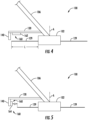
FIG. 4 is a view of trimmer head with a sensor in accordance with one or more embodiments of the present disclosure; -
FIG. 5 is a view of another trimmer head with a sensor in accordance with one or more embodiments of the present disclosure; -
FIG. 6 is view of a trimmer line spool with a spool sensor in accordance with one or more embodiments of the present disclosure; -
FIG. 7 is a view of a trimmer with an auto advance mechanism in accordance with one or more embodiments of the present disclosure; -
FIG. 8 is a view of another trimmer with an auto advance mechanism in accordance with one or more embodiments of the present disclosure; -
FIG. 9 is a view of yet another trimmer with an auto advance mechanism in accordance with one or more embodiments of the present disclosure; and -
FIG. 10 is an exemplary method for auto advancing a trimmer in accordance with one or more embodiments of the present disclosure; - Reference now will be made in detail to embodiments of the present invention, one or more examples of which are illustrated in the drawings. The word "exemplary" is used herein to mean "serving as an example, instance, or illustration." Any implementation described herein as "exemplary" is not necessarily to be construed as preferred or advantageous over other implementations. Moreover, each example is provided by way of explanation, rather than limitation of, the technology. In fact, it will be apparent to those skilled in the art that modifications and variations can be made in the present technology without departing from the scope or spirit of the claimed technology. For instance, features illustrated or described as part of one embodiment can be used with another embodiment to yield a still further embodiment. Thus, it is intended that the present disclosure covers such modifications and variations as come within the scope of the appended claims and their equivalents. The detailed description uses numerical and letter designations to refer to features in the drawings. Like or similar designations in the drawings and description have been used to refer to like or similar parts of the invention.
- As used herein, the terms "first", "second", and "third" may be used interchangeably to distinguish one component from another and are not intended to signify location or importance of the individual components. The singular forms "a," "an," and "the" include plural references unless the context clearly dictates otherwise. The terms "coupled," "fixed," "attached to," and the like refer to both direct coupling, fixing, or attaching, as well as indirect coupling, fixing, or attaching through one or more intermediate components or features, unless otherwise specified herein. As used herein, the terms "comprises," "comprising," "includes," "including," "has," "having" or any other variation thereof, are intended to cover a non-exclusive inclusion. For example, a process, method, article, or apparatus that comprises a list of features is not necessarily limited only to those features but may include other features not expressly listed or inherent to such process, method, article, or apparatus. Further, unless expressly stated to the contrary, "or" refers to an inclusive- or and not to an exclusive- or. For example, a condition A or B is satisfied by any one of the following: A is true (or present) and B is false (or not present), A is false (or not present) and B is true (or present), and both A and B are true (or present).
- Terms of approximation, such as "about," "generally," "approximately," or "substantially," include values within ten percent greater or less than the stated value. When used in the context of an angle or direction, such terms include within ten degrees greater or less than the stated angle or direction. For example, "generally vertical" includes directions within ten degrees of vertical in any direction, e.g., clockwise or counter-clockwise.
- Benefits, other advantages, and solutions to problems are described below with regard to specific embodiments. However, the benefits, advantages, solutions to problems, and any feature(s) that may cause any benefit, advantage, or solution to occur or become more pronounced are not to be construed as a critical, required, or essential feature of any or all the claims.
- In general, trimmers described in accordance with one or more embodiments herein include sensors and auto advance mechanisms that cooperate to selectively and automatically advance trimmer line without requiring manual bumping. The sensors can directly or indirectly determine the length of the trimmer line during operation of the trimmer. The length can then continuously or iteratively be compared to a predetermined threshold value such as a minimum desired length of trimmer line. When the length of trimmer line falls below the predetermined threshold value, the auto advance mechanism can automatically advance the trimmer line, such as in discrete intervals or continuously until the new length is sufficient. The trimmers shown and described herein can thereby allow for the automatic advancement of trimmer line without manual input and without wasting excessive trimmer line.
- Referring now to the drawings,
FIG. 1 illustrates atrimmer 100 including atrimmer head 102, ahousing 104, and a connectingmember 106 extending between thetrimmer head 102 and thehousing 104. Thehousing 104 may include aport 108 configured to be electrically connected with a power source, such as a battery (not illustrated) or wall outlet. Theport 108 is illustrated as being disposed at afirst end 110 of thetrimmer 100 and thetrimmer head 102 is disposed at asecond end 112 of thetrimmer 100. In other embodiments, either one or both of theport 108 ortrimmer head 102 can be spaced apart from thefirst end 110 orsecond end 112, respectively. In certain instances, thetrimmer 100 may be electrically powered, e.g., via the battery or through a wall outlet. In other instances, thetrimmer 100 may be powered by a fuel, such as gasoline. - A
handle 114 can be disposed along the connectingmember 106, thehousing 104, or another portion of thetrimmer 100, to form a handle assembly. Thehandle 114 can allow the operator to support the weight of thetrimmer 100 during operation. Agrip 116 can be disposed along the connectingmember 106 to permit a second point of contact for the operator. Thegrip 116 can include, for example, a portion of the connectingmember 106 including auser interface 118. Theuser interface 118 can include a trigger that allows the operator to selectively control thetrimmer 100. Theuser interface 118 can further include other controls which permit the operator to effect change to thetrimmer 100. For instance, by way of non-limiting example, theuser interface 118 may include any one or more of a cruise control feature allowing the operator to maintain the operating speed of thetrimmer head 102, a turbo which allows thetrimmer 100 to reach full operational speed, a power switch having at least ON and OFF functionality, a safety, or any other desirable user controls. As described in greater detail below, theuser interface 118 can include a trimmer line advance interface configured to selectively feed trimmer line from the cartridge when actuated. In the illustrated embodiment, thegrip 116 anduser interface 118 are disposed between thehandle 114 and theport 108. In other embodiments, the relatively arrangement of thegrip 116,user interface 118, handle 114, andport 108 can be adjusted. - In certain embodiments, the
trimmer 100 can further include aguard 120 configured to protect the operator from flying debris kicked up by thetrimmer head 102. In certain instances, theguard 120 can be engaged with the connectingmember 106 and be disposed adjacent to thetrimmer head 102. Features of theguard 120 will be described in further detail below. - Referring to
FIG. 2 , thetrimmer head 102 can generally include a power source, e.g., amotor 122, configured to drive asubassembly 124 including aflywheel 126 and a cartridge 128 (FIG. 3 ) containingtrimmer line 129. Thesubassembly 124 can be maintained in operative connection with themotor 122 by anactuation member 130. Theactuation member 130 can be selectively moved between an engaged configuration in which thesubassembly 124 is coupled to themotor 122 and a disengaged configuration in which the subassembly is detachable from themotor 122. Engaging and disengaging theactuation member 130 can be performed by the operator. When engaged, theactuation member 130 can maintain thetrimmer head 102 in a ready-to-use configuration. Theactuation member 130 may also protect one or more components of thetrimmer head 102 from being impacted or contaminated by debris which might induce unintended feeding of trimmer line from thetrimmer head 102. - The
motor 122 can define an axis of rotation A about which thesubassembly 124 is rotatable. In an embodiment, theactuation member 130 may be moveable between the engaged and disengaged configurations by translating theactuation member 130, or a portion thereof (as described in greater detail below), in a direction generally along the axis of rotation A. For example, in an embodiment, theactuation member 130 can be moved to the engaged configuration by translating theactuation member 130, or a portion thereof, along the axis of rotation A in a direction towards themotor 122. Theactuation member 130 can be moved to the disengaged configuration by translating theactuation member 130, or a portion thereof, along the axis of rotation A in a direction away from themotor 122. In another embodiment, these directions may be switched such that theactuation member 130 is moved to the engaged configuration by translating theactuation member 130, or a portion thereof, along the axis of rotation A in a direction away from themotor 122 and moved to the disengaged configuration by translating theactuation member 130, or a portion thereof along the axis of rotation A in a direction toward themotor 122. -
FIG. 3 illustrates an exploded view of thetrimmer head 102 as seen in accordance with an exemplary embodiment of the present disclosure. Ahousing 132 can be disposed between themotor 122 and thecartridge 128. In an embodiment, thehousing 132 can be rotationally keyed with themotor 122 such that rotational input from themotor 122 causes thehousing 132 to rotate. Ashaft 133 of themotor 122 can extend through thehousing 132 and pass through at least a portion of thesubassembly 124. In certain instances, theshaft 133 can rotatably drive thehousing 132. - In an embodiment, the
housing 132 can be disposed between thesubassembly 124 and themotor 122. In an embodiment, thecartridge 128 can be disposed between theflywheel 126 and thehousing 132. In an embodiment, theflywheel 126 may extend radially beyond thehousing 132 such that a portion of theflywheel 126 is exposed from thetrimmer head 102. In an embodiment, thesubassembly 124 can be disposed between thehousing 132 and theactuation member 130. It should be understood that other spatial arrangements are contemplated herein and that the above-described relative positions of the elements are exemplary only. - In certain instances, the
cartridge 128 can be a single-use cartridge. Single-use cartridges allow the operator to replace exhausted cartridges without having to wind trimmer line. That is, the operator can dispose of eachcartridge 128 after exhausting the trimmer line associated with that cartridge and replace the exhausted cartridge with a new cartridge already having trimmer line wound thereon. In this regard, replacement of the trimmer line does not require the operator to wind new trimmer line. Instead, the operator can simply replace the exhausted cartridge and resume operation of thetrimmer 100. In certain instances, thecartridge 128 can be made using recycled materials. In an embodiment, thecartridge 128 can be reusable. For example, the operator can manually wind trimmer line to thecartridge 128. In this regard, the operator is not left with anunusable cartridge 128 after the trimmer line is depleted. -
Trimmer line 129 is generally expended during operational use of thetrimmer 100. For example, when performing trimming operations, thetrimmer line 129 can become worn or frayed. For instance, upon contacting hard surfaces like rocks, walls, and posts at high speeds, the trimmer line can break. To continue operations after fraying or breaking,additional trimmer line 129 must be dispensed (or fed) from thecartridge 128. - Referring now to
FIGS. 4-6 , thetrimmer 100 can further comprise asensor 160. Thesensor 160 can comprise any suitable device, apparatus, or system configured to determine a length L of thetrimmer line 129 extending from thetrimmer head 102. In some embodiments, the length L of thetrimmer line 129 may be measured directly. That is, the physical distance between thetrimmer head 102 and the end of thetrimmer line 129 that is outside of thetrimmer head 102 may be measured through one or more means. In some embodiments, the length L may be measured indirectly wherein a separate measurement enables the deduction of the actual length L of thetrimmer line 129. For example, the distance between the end point of thetrimmer line 129 and a separate reference point may be measured, wherein said distance inherently correlates to the physical length of thetrimmer line 129. - Multiple types of
sensors 160 and operational parameters may be utilized to determine the length L of thetrimmer line 129. For example, with particular reference toFIG. 4 , in some embodiments thesensor 160 may comprise anoptical sensor 162. Theoptical sensor 162 may comprise an optical device such as a camera or photodiode that can detect thetrimmer line 129 at one or more locations near or about thetrimmer head 102 or its auxiliary components. Theoptical sensor 162 may be capable of detecting thetrimmer line 129 when thetrimmer line 129 is being rotated about the axis of rotation A. Such embodiments may allow for determination of the length L of the trimmer line when it is at maximum extension due to centrifugal force. Alternatively, or additionally, theoptical sensor 162 may be capable of detecting thetrimmer line 129 when thetrimmer line 129 is stationary. Such embodiments may allow for more accurate detection of the line due to reduced movement, vibration, and other environmental factors. - The
optical sensor 162 can be disposed in a variety of locations about thetrimmer 100, thetrimmer head 102, or other auxiliary components. For example, in some embodiments, theoptical sensor 162 may be disposed underneath theguard 120. Additionally, or alternatively, theoptical sensor 162 may be disposed between thecutter 140 and thetrimmer head 102. In such embodiments, the optical sensor may be disposed closer to thecutter 140 than thetrimmer head 102. - With particular reference to
FIG. 5 , in some embodiments thesensor 160 may comprise aHall sensor 164. TheHall sensor 164 may comprise any device or devices capable of detecting the presence of a magnetic field using the Hall effect. In such embodiments, thetrimmer line 129 or some other suitable derivation, can influence the strength of the magnetic field detected by theHall sensor 164 based on its length L. In order to influence the strength of the magnetic field, thetrimmer line 129 can comprise a ferrous or partially ferrous material. For example, as illustrated inFIG. 6 , thetrimmer line 129 may comprise a plurality offerrous particles 151 embedded in, disposed on, coated with, coated on, or otherwise combined with aplastic line 152. Theferrous particles 151 may be substantially distributed throughout or about thetrimmer line 129 to limit or avoid long stretches oftrimmer line 129 that would not be detected by theHall sensor 164. In other embodiments, thetrimmer line 129 may entirely consist of, or nearly entirely consist of, a ferrous material itself. - The
Hall sensor 164 may be used to determine a distance D separating theHall sensor 164 and thetrimmer line 129, such as the end of thetrimmer line 129. Based on where theHall sensor 164 is disposed with respect to thetrimmer head 102, the distance D determined by theHall sensor 164 may be used to deduce the length L of thetrimmer line 129. For example, the distance D between theHall sensor 164 and thetrimmer line 129 may be deducted from a total distance between theHall sensor 164 and thetrimmer head 102 to determine the length L of the trimmer line. - The
Hall sensor 164 can be disposed in a variety of locations about thetrimmer 100, thetrimmer head 102, or other auxiliary components. For example, in some embodiments, theHall sensor 164 may be disposed underneath theguard 120. Additionally, or alternatively, theHall sensor 164 may be disposed on thecutter 140. In these or other embodiments, theHall sensor 164 may be disposed between thecutter 140 and thetrimmer head 102. - With particular reference to
FIG. 6 , in some embodiments thesensor 160 may comprise adraw sensor 166. Thedraw sensor 166 can comprise any device capable of determining (e.g., measuring, tracking, or the like), the amount oftrimmer line 129 drawn out from atrimmer line spool 150. - The
draw sensor 166 may monitor thetrimmer line 129 itself as its drawn from thetrimmer line spool 150, may monitor thetrimmer line spool 150 itself (e.g., as it rotates), or otherwise reference some movement indicative of drawingadditional trimmer line 129. For example, thedraw sensor 166 may detect every time thetrimmer line spool 150 rotates. This detection may further be combined with additional variables to deduce an approximation of the length L of thetrimmer line 129. For example, the measurement(s) from thedraw sensor 166 may be combined with one or more operational parameters of thetrimmer 100 such as run time, activation frequency, manual advancements oftrimmer line 129. The combination ofdraw sensor 166 feedback and other operational parameters may then be correlated to derive a rough approximation of the length L of thetrimmer line 129. This determination may be based on pre-programed algorithms, may be manually adjusted based on operator input(s), and/or may dynamically evolve such as through machine learning. - The
draw sensor 166 can be disposed in a variety of locations about thetrimmer 100, thetrimmer head 102, or other auxiliary components. For example, in some embodiments, thedraw sensor 166 may be disposed underneath theguard 120. Additionally, or alternatively, thedraw sensor 166 may be disposed about thetrimmer line spool 150, such as mounted directly on thetrimmer line spool 150 or mounted adjacent to thetrimmer line spool 150. - While reference and illustrations have been made to
various sensors 160 and their locations, it should be appreciated that additional oralternative sensors 160 may also be realized within the scope of this disclosure. For example, thetrimmer 100 may comprise a plurality ofsensors 160 comprising the same type ofsensors 160 or a variety ofdifferent sensors 160. Further, thesensors 160 may be pre-installed on thetrimmer 100,trimmer head 102, or other auxiliary components, or may be manually added to said components by an operator. - Referring now to
FIGS. 7-9 , thetrimmer 100 can further comprise anauto advance mechanism 170. Theauto advance mechanism 170 can comprise any suitable device, apparatus, or system configured to advance thetrimmer line 129 and extend its length L away from thetrimmer head 102. - Multiple types of
auto advance mechanisms 170 may be utilized. For example, with reference toFIG. 7 , a stepper motor 172 may be utilized to advance thetrimmer line 129. The stepper motor 172 may be configured to actuate anactuation member 130 of thetrimmer head 102 to advance thetrimmer line 129. The actuation mechanism by the stepper motor 172 of theactuation member 130 will depend on the type and structure of theactuation member 130 itself. For example, if theactuation member 130 comprises a compressible spring similar to a bump advancement mechanism, the stepper motor 172 may compress the spring to mimic a bump input and advance thetrimmer line 129. - The stepper motor 172 can be disposed in a variety of locations about the
trimmer 100, thetrimmer head 102, or other auxiliary components. For example, the stepper motor 172 may be disposed on top of or adjacent to thetrimmer head 102 such that it is operably connected to theactuation member 130. - With reference to
FIG. 8 , a secondary motor 174 may be utilized to advance thetrimmer line 129. The secondary motor 174 may be configured to rotate the trimmer line spool 150 (FIG. 6 ) to advance thetrimmer line 129. The advancement or rotation mechanism by the secondary motor 174 of the trimmer line spool will depend on the type and structure of thetrimmer line spool 150 and the secondary motor 174. For example, the secondary motor 174 may be in an operational connection with the trimmer line spool via one or more gears such that when the secondary motor 174 is activated, it causes rotation (either directly or indirectly) of thetrimmer line spool 150 such that thetrimmer line 129 is extended therefrom. - The stepper motor 172 can be disposed in a variety of locations about the
trimmer 100, thetrimmer head 102, or other auxiliary components. For example, the stepper motor 172 may be disposed adjacent to or integral with thetrimmer line spool 150. - With reference to
FIG. 9 , a centrifugal clutch 176 may be utilized to advance thetrimmer line 129. The centrifugal clutch 176 may be in an operable connection with themotor 122 of the trimmer 100 (or any other power source) to selectively advance thetrimmer line 129 based on the rotational speed of the centrifugal clutch 176. That is, when themotor 122 or other power source causes the centrifugal clutch 176 to rotate past a threshold speed, the centrifugal clutch 176 can become engaged with the trimmer line spool 150 (FIG. 6 ) such that it rotates and advances thetrimmer line 129. When themotor 122 or other power source reduces the speed of the centrifugal clutch 176 below the threshold speed, then the centrifugal clutch 176 becomes disengaged with thetrimmer line spool 150 such that it no longer rotates. Such embodiments may allow for only requiring onemotor 122 to both operate the trimmer when trimming grass or weeds as well as selectively advance thetrimmer line 129. - The threshold force required for activation of the centrifugal clutch 176 can be greater than the standard operating speed of the
trimmer 100 to prevent continuous advancement of thetrimmer line 129 during routine operation. Instead, when the length L of thetrimmer line 129 falls below a predetermined threshold value thereby triggering theauto advance mechanism 170, thetrimmer 100 may momentarily speed up rotation to active the centrifugal clutch 176 so that it engages with thetrimmer line spool 150 and advances thetrimmer line 129 before slowing back down thetrimmer 100 into the normal operational speed. - The centrifugal clutch 176 can be disposed in a variety of locations about the
trimmer 100, thetrimmer head 102, or other auxiliary components. For example, the centrifugal clutch 176 may be disposed adjacent to or integral with thetrimmer line spool 150 or otherwise between themotor 122 and thetrimmer line spool 150. - While reference and illustrations have been made to
auto advance mechanisms 170 and their operations, it should be appreciated that additional or alternativeauto advance mechanisms 170 may also be realized within the scope of this disclosure. For example, thetrimmer 100 may comprise a plurality ofauto advance mechanisms 170. Further, theauto advance mechanism 170 may be pre-installed on thetrimmer 100,trimmer head 102, or other auxiliary components, or may be manually added to said components by an operator. - In operation, the
trimmer 100 may thereby determine a length L of thetrimmer line 129 using thesensor 160 and, based on feedback from thesensor 160, auto advance thetrimmer line 129 using theauto advance mechanism 170. The determination may be based on pre-programed algorithms, may be manually adjusted based on operator input(s), and/or may dynamically evolve such as through machine learning. - The length L can then be compared to, for example, a predetermined threshold value. The predetermined threshold value may be factory preset, manually defined, adjustable from an initial default value. The comparison of the length L to the predetermined value may happen onboard the
trimmer 100 itself such as via any suitable control system(s), programable logic controller(s), computer readable medium(s), or the like which are sufficient to perform comparisons and, based on said comparisons, selectively trigger theauto advance mechanism 170. - Moreover, in some embodiments, the auto advancement feature of the
trimmer line 129 may be selectively engaged or disengaged by an operator, or even automatically based on, for example, the type oftrimmer line 129 ortrimmer line spool 150 installed on thetrimmer 100. - Referring now to
FIG. 10 , and with continued structural reference for illustrative purposes to the elements exemplary illustrated inFIGS. 1-9 , an exemplary method 500 is illustrated for auto advancing thetrimmer 100. The method 500 first comprises determining a length L of atrimmer line 129 extending from thetrimmer head 102 instep 510. As discussed herein, the determination instep 510 may be accomplished using a variety ofpotential sensors 160 such as anoptical sensor 162, ahall sensor 164, and/or adraw sensor 166. Moreover, the determination made instep 510 may be based on pre-programed algorithms, may be manually adjusted based on operator input(s), and/or may dynamically evolve such as through machine learning. - The method 500 further comprises comparing the length L to a predetermined threshold value in
step 520. The predetermined threshold value may, for example, be factory preset, manually defined, adjustable from an initial default value. Moreover, the comparison of the length L to the predetermined value may happen onboard thetrimmer 100 itself such as via any suitable control system, programable logic controller, computer readable medium, or the like which is sufficient to perform comparisons. - The method 500 further comprises automatically advancing the
trimmer line 129 instep 530 if the length L falls below the predetermined threshold value. As discussed herein, the auto advancement of thetrimmer line 129 instep 530 may be accomplished using a variety of potentialauto advance mechanisms 170 such as a stepper motor 172, a secondary motor 174, and/or a centrifugal clutch 176. - The method 500 may run in a continuous loop, may run in a periodic iterative fashion, or may run selectively based on manual request.
- Further aspects of the invention are provided by one or more of the following embodiments:
- A trimmer comprising a trimmer head disposed on a connecting member; a user interface disposed on the connecting member, wherein the user interface is configured to operate the trimmer head; a sensor configured to determine a length of a trimmer line extending from the trimmer head; and, an auto advance mechanism configured to extend the trimmer line extending from the trimmer head based on feedback from the sensor.
- The trimmer of any one or more of the embodiments disclosed herein, wherein the sensor comprises a draw sensor configured to determine how much of the trimmer line has been drawn from a trimmer line spool.
- The trimmer of any one or more of the embodiments disclosed herein, wherein the sensor comprises a Hall sensor.
- The trimmer of any one or more of the embodiments disclosed herein, wherein the Hall sensor is disposed on a guard at least partially enclosing the trimmer head.
- The trimmer of any one or more of the embodiments disclosed herein, wherein the Hall sensor is disposed on a cutter.
- The trimmer of any one or more of the embodiments disclosed herein, wherein the trimmer line comprises ferrous particles embedded in a plastic line.
- The trimmer of any one or more of the embodiments disclosed herein, wherein the auto advance mechanism comprises a stepper motor operable to comprises a spring in the trimmer head to advance the trimmer line.
- The trimmer of any one or more of the embodiments disclosed herein, wherein the auto advance mechanism comprises a secondary motor configured to rotate a trimmer line spool in the trimmer head.
- The trimmer of any one or more of the embodiments disclosed herein, wherein the auto advance mechanism comprises a centrifugal clutch operably connected to a trimmer line spool.
- The trimmer of any one or more of the embodiments disclosed herein, wherein the auto advance mechanism automatically extends the trimmer line when the length falls below a predetermined threshold value.
- A method for auto advancing a trimmer line of a trimmer, the method comprising determining a length of the trimmer line extending from a trimmer head; comparing the length to a predetermined threshold value; and, automatically advancing the trimmer line if the length falls below the predetermined threshold value.
- An apparatus of any one or more of the embodiments disclosed herein as shown and described in one or more embodiments herein.
- A method in accordance with any one or more of the embodiments disclosed herein as shown and described in one or more embodiments herein.
- A control system configured to operate in accordance with any one or more of the embodiments disclosed herein.
- This written description uses examples to disclose the invention, including the best mode, and also to enable any person skilled in the art to practice the invention, including making and using any devices or systems and performing any incorporated methods. The patentable scope of the invention is defined by the claims, and may include other examples that occur to those skilled in the art. Such other examples are intended to be within the scope of the claims if they include structural elements that do not differ from the literal language of the claims, or if they include equivalent structural elements with insubstantial differences from the literal language of the claims.
Claims (12)
- A trimmer comprising:a trimmer head disposed on a connecting member;a user interface disposed on the connecting member, wherein the user interface is configured to operate the trimmer head;a sensor configured to determine a length of a trimmer line extending from the trimmer head; and,an auto advance mechanism configured to extend the trimmer line extending from the trimmer head based on feedback from the sensor.
- The trimmer of claim 1, wherein the sensor comprises a draw sensor configured to determine how much of the trimmer line has been drawn from a trimmer line spool.
- The trimmer of claim 1, wherein the sensor comprises a Hall sensor.
- The trimmer of claim 3, wherein the Hall sensor is disposed on a guard at least partially enclosing the trimmer head.
- The trimmer of claim 3, wherein the Hall sensor is disposed on a cutter.
- The trimmer of claim 3, wherein the trimmer line comprises ferrous particles embedded in a plastic line.
- The trimmer of claim 1, wherein the auto advance mechanism comprises a stepper motor operable to compress a spring in the trimmer head to advance the trimmer line.
- The trimmer of claim 1, wherein the auto advance mechanism comprises a secondary motor configured to rotate a trimmer line spool in the trimmer head.
- The trimmer of claim 1, wherein the auto advance mechanism comprises a centrifugal clutch operably connected to a trimmer line spool.
- The trimmer of claim 1, wherein the auto advance mechanism automatically extends the trimmer line when the length falls below a predetermined threshold value.
- A method for auto advancing a trimmer line of a trimmer, the method comprising:determining a length of the trimmer line extending from a trimmer head;comparing the length to a predetermined threshold value; and,automatically advancing the trimmer line if the length falls below the predetermined threshold value.
- The method of claim 11, further comprising a trimmer, the trimmer comprising:the trimmer head disposed on a connecting member;a user interface disposed on the connecting member, wherein the user interface is configured to operate the trimmer head;a sensor configured to determine a length of the trimmer line extending from the trimmer head; and,an auto advance mechanism configured to extend the trimmer line extending from the trimmer head based on feedback from the sensor.
Applications Claiming Priority (1)
| Application Number | Priority Date | Filing Date | Title |
|---|---|---|---|
| US202263349613P | 2022-06-07 | 2022-06-07 |
Publications (2)
| Publication Number | Publication Date |
|---|---|
| EP4311416A2 true EP4311416A2 (en) | 2024-01-31 |
| EP4311416A3 EP4311416A3 (en) | 2024-03-20 |
Family
ID=86646726
Family Applications (1)
| Application Number | Title | Priority Date | Filing Date |
|---|---|---|---|
| EP23176335.0A Pending EP4311416A3 (en) | 2022-06-07 | 2023-05-31 | Trimmers and auto advancing trimmer lines |
Country Status (3)
| Country | Link |
|---|---|
| US (1) | US20230389470A1 (en) |
| EP (1) | EP4311416A3 (en) |
| CN (1) | CN220307808U (en) |
Family Cites Families (2)
| Publication number | Priority date | Publication date | Assignee | Title |
|---|---|---|---|---|
| CN107996122A (en) * | 2016-10-28 | 2018-05-08 | 苏州宝时得电动工具有限公司 | Grass-mowing machine and its line-putting method |
| SE1850147A1 (en) * | 2018-02-12 | 2019-08-13 | Husqvarna Ab | Trimmer head and trimmer |
-
2023
- 2023-05-26 US US18/324,539 patent/US20230389470A1/en active Pending
- 2023-05-31 EP EP23176335.0A patent/EP4311416A3/en active Pending
- 2023-06-05 CN CN202321401108.2U patent/CN220307808U/en active Active
Also Published As
| Publication number | Publication date |
|---|---|
| CN220307808U (en) | 2024-01-09 |
| EP4311416A3 (en) | 2024-03-20 |
| US20230389470A1 (en) | 2023-12-07 |
Similar Documents
| Publication | Publication Date | Title |
|---|---|---|
| US4236312A (en) | Apparatus for cutting vegetation | |
| US8888417B2 (en) | Drilling device with a controller for the feeding unit | |
| US4483069A (en) | Apparatus for cutting vegetation | |
| EP2798934B1 (en) | Vegetation cutting device | |
| US20120138322A1 (en) | Handheld Work Apparatus with Switchable Power | |
| CN105988472B (en) | Intelligent mowing system, intelligent mower and trimming method thereof | |
| CN102655736A (en) | Mower and protective cover therefor | |
| US9801342B2 (en) | Method for determining the sharpness of cutting edges of chopper blades | |
| EP2969424B1 (en) | Power table saw with guard detection system | |
| US6722238B2 (en) | Method and device for feeding and cutting a rolled transfer paper with improved operability | |
| EP4311416A2 (en) | Trimmers and auto advancing trimmer lines | |
| US20090217637A1 (en) | Method and apparatus for swinging line | |
| JP7289561B2 (en) | Electric working machine with cutting blade | |
| US20180355930A1 (en) | Work apparatus having an electromagnetic brake assembly | |
| EP2253190A1 (en) | Work apparatus with safety equipment | |
| CN110177455B (en) | Grass trimmer | |
| EP4154696A1 (en) | Trimmer guard and trimmer | |
| CN110213960B (en) | Grass trimmer | |
| CN110337936B (en) | Grass trimmer | |
| US11279152B2 (en) | Printing apparatus and method of controlling printing apparatus | |
| US20230011491A1 (en) | Single line weed vegetation trimmer and/or edger with continuous line feed | |
| JP2011218468A (en) | Apparatus and method for detecting guide pulley abrasion of wire saw | |
| EP4082322A2 (en) | Lawnmower collection vessel fill indicator assemblies | |
| CN210256309U (en) | Cutter mechanism of release film splitting machine | |
| GB2479542A (en) | Cutting Ink Cartridge In Axial and Lateral Directions |
Legal Events
| Date | Code | Title | Description |
|---|---|---|---|
| PUAI | Public reference made under article 153(3) epc to a published international application that has entered the european phase |
Free format text: ORIGINAL CODE: 0009012 |
|
| STAA | Information on the status of an ep patent application or granted ep patent |
Free format text: STATUS: THE APPLICATION HAS BEEN PUBLISHED |
|
| AK | Designated contracting states |
Kind code of ref document: A2 Designated state(s): AL AT BE BG CH CY CZ DE DK EE ES FI FR GB GR HR HU IE IS IT LI LT LU LV MC ME MK MT NL NO PL PT RO RS SE SI SK SM TR |
|
| PUAL | Search report despatched |
Free format text: ORIGINAL CODE: 0009013 |
|
| AK | Designated contracting states |
Kind code of ref document: A3 Designated state(s): AL AT BE BG CH CY CZ DE DK EE ES FI FR GB GR HR HU IE IS IT LI LT LU LV MC ME MK MT NL NO PL PT RO RS SE SI SK SM TR |
|
| RIC1 | Information provided on ipc code assigned before grant |
Ipc: A01D 34/00 20060101AFI20240214BHEP |