EP4311240A2 - Partitioning method and signaling method for partitioning a coding tree unit - Google Patents
Partitioning method and signaling method for partitioning a coding tree unit Download PDFInfo
- Publication number
- EP4311240A2 EP4311240A2 EP23214427.9A EP23214427A EP4311240A2 EP 4311240 A2 EP4311240 A2 EP 4311240A2 EP 23214427 A EP23214427 A EP 23214427A EP 4311240 A2 EP4311240 A2 EP 4311240A2
- Authority
- EP
- European Patent Office
- Prior art keywords
- sub
- subdivision
- current block
- ctu
- type
- Prior art date
- Legal status (The legal status is an assumption and is not a legal conclusion. Google has not performed a legal analysis and makes no representation as to the accuracy of the status listed.)
- Pending
Links
- 238000000034 method Methods 0.000 title claims abstract description 43
- 238000000638 solvent extraction Methods 0.000 title description 15
- 230000011664 signaling Effects 0.000 title description 7
- 238000011002 quantification Methods 0.000 claims abstract description 17
- 230000000295 complement effect Effects 0.000 claims abstract description 11
- 238000004590 computer program Methods 0.000 claims description 8
- 230000009466 transformation Effects 0.000 description 24
- 238000012545 processing Methods 0.000 description 18
- 102100036464 Activated RNA polymerase II transcriptional coactivator p15 Human genes 0.000 description 10
- 101000713904 Homo sapiens Activated RNA polymerase II transcriptional coactivator p15 Proteins 0.000 description 10
- 229910004444 SUB1 Inorganic materials 0.000 description 10
- 241001080024 Telles Species 0.000 description 7
- 238000004364 calculation method Methods 0.000 description 7
- 229910004438 SUB2 Inorganic materials 0.000 description 6
- 101100311330 Schizosaccharomyces pombe (strain 972 / ATCC 24843) uap56 gene Proteins 0.000 description 6
- 230000008569 process Effects 0.000 description 6
- 101150018444 sub2 gene Proteins 0.000 description 6
- 101150080287 SUB3 gene Proteins 0.000 description 5
- 230000033001 locomotion Effects 0.000 description 5
- 101150023658 SUB4 gene Proteins 0.000 description 4
- 230000003044 adaptive effect Effects 0.000 description 4
- 230000008901 benefit Effects 0.000 description 4
- 239000013598 vector Substances 0.000 description 4
- 230000005540 biological transmission Effects 0.000 description 3
- 238000012986 modification Methods 0.000 description 3
- 230000004048 modification Effects 0.000 description 3
- 101100536354 Drosophila melanogaster tant gene Proteins 0.000 description 2
- 241000861223 Issus Species 0.000 description 2
- 101150029328 SUB6 gene Proteins 0.000 description 2
- 101150067183 SUB9 gene Proteins 0.000 description 2
- 238000004422 calculation algorithm Methods 0.000 description 2
- 230000006835 compression Effects 0.000 description 2
- 238000007906 compression Methods 0.000 description 2
- 229940082150 encore Drugs 0.000 description 2
- 230000003287 optical effect Effects 0.000 description 2
- 230000009467 reduction Effects 0.000 description 2
- 238000012360 testing method Methods 0.000 description 2
- 101150027645 SUB10 gene Proteins 0.000 description 1
- 101150087985 SUB11 gene Proteins 0.000 description 1
- 101150025868 SUB12 gene Proteins 0.000 description 1
- 101150086029 SUB5 gene Proteins 0.000 description 1
- 101150061527 SUB7 gene Proteins 0.000 description 1
- 101150004790 SUB8 gene Proteins 0.000 description 1
- 238000006073 displacement reaction Methods 0.000 description 1
- 238000005206 flow analysis Methods 0.000 description 1
- 238000004377 microelectronic Methods 0.000 description 1
- 238000013519 translation Methods 0.000 description 1
Images


Classifications
-
- H—ELECTRICITY
- H04—ELECTRIC COMMUNICATION TECHNIQUE
- H04N—PICTORIAL COMMUNICATION, e.g. TELEVISION
- H04N19/00—Methods or arrangements for coding, decoding, compressing or decompressing digital video signals
- H04N19/90—Methods or arrangements for coding, decoding, compressing or decompressing digital video signals using coding techniques not provided for in groups H04N19/10-H04N19/85, e.g. fractals
- H04N19/96—Tree coding, e.g. quad-tree coding
Definitions
- the present invention relates generally to the field of image processing, and more specifically to the decoding of digital images and digital image sequences.
- the invention can be applied in particular, but not exclusively, to video coding implemented in current AVC and HEVC video encoders and their extensions (MVC, 3D-AVC, MV-HEVC, 3D-HEVC, etc.), as well as 'to the corresponding decoding.
- Current video encoders use a block representation of the images to be encoded.
- the images are subdivided into square or rectangular blocks, which can in turn be subdivided recursively.
- a recursive subdivision respects a tree structure called “quadtree”.
- a current image I N is subdivided a first time into a plurality of square or rectangular blocks called CTU (from the English “Coding Tree Unit”), designated by CTU 1 , CTU 2 , ..., CTUi, ... , CTU L.
- Such blocks are for example of size 64x64 pixels (1 ⁇ i ⁇ L).
- the partitioning iteration of the CTUi block is performed up to a predetermined partitioning depth level.
- the latter is ultimately partitioned into a plurality of coding blocks denoted UC 1 , UC 2 , ..., UC j , ..., UC M with 1 ⁇ j ⁇ M.
- the aim of such a subdivision is to delimit areas which adapt well to the local characteristics of the image, such as for example a homogeneous texture, constant movement, a foreground object in the image, etc. .
- a sequence of digital information such as for example a series of bits, representative of this optimal subdivision, is transmitted in a data signal intended to be stored in the encoder or else transmitted to a video decoder for playback, then decoded by the latter.
- the seventeen aforementioned bits are written one after the other in the binary sequence which is then compressed by a suitable entropic coding.
- a prediction of pixels of the sub-block considered is implemented in relation to prediction pixels which belong either to the same image (intra prediction), or to one or more previous images of a sequence of images (inter prediction) which have already been decoded.
- Such previous images are conventionally called reference images and are stored in memory both at the encoder and at the decoder.
- a residual sub-block is calculated by subtracting the pixels of the sub-block considered from the prediction pixels.
- the coefficients of the calculated residual sub-block are then quantified after a possible mathematical transformation, for example of the discrete cosine transform (DCT) type, then coded by an entropic encoder.
- DCT discrete cosine transform
- inter or intra prediction mode is made at the level of each of the sub-blocks UC 1 , UC 2 , ..., UC j , ..., UC M which can themselves be partitioned into prediction sub-blocks (“Prediction Units” in English) and transform sub-blocks (“Transform Units” in English).
- prediction sub-blocks Prediction Units” in English
- transform sub-blocks Transform Units” in English.
- Each of the prediction sub-blocks and the transform sub-blocks are in turn capable of being subdivided recursively into sub-blocks according to the aforementioned “quadtree” tree structure.
- the CTUi block as well as its sub-blocks UC 1 , UC 2 , ..., UC j , ..., UC M , its prediction sub-blocks and its transform sub-blocks, are likely to be associated with information describing their content.
- This information is also recorded in the aforementioned data signal.
- a disadvantage of such a subdivision is that it requires the transmission of a binary sequence representative of this subdivision which contains a non-negligible number of bits. Such a sequence proves costly to signal, which does not make it possible to optimize the reduction of the compression gain of the coded data. This results in compression performance that is not satisfactory.
- One of the aims of the invention is to remedy the drawbacks of the aforementioned state of the art.
- the invention relates to a method for decoding a data signal representative of at least one coded image having been subdivided into a plurality of blocks.
- the subdivision according to the invention is particularly well suited to the case where blocks of the image to be decoded contain an element significant, for example a foreground object, which is located in a homogeneous area having low energy, such as for example a background of uniform color, orientation or movement.
- an element significant for example a foreground object, which is located in a homogeneous area having low energy, such as for example a background of uniform color, orientation or movement.
- the decoding method further comprises decoding, in association with the decoded data of the first part, of a value of a syntax element read in the data signal, said value corresponding to a Intra or Inter prediction to apply to the first part.
- At least one reconstruction information of the pixels of the second part at m sides of the current block is set to a predetermined value.
- An advantage of such an arrangement lies in the fact that the decoder autonomously determines said at least one piece of information for reconstructing the pixels of the second part with m sides.
- said at least one piece of corresponding reconstruction information is advantageously not transmitted in the data signal received at the decoder.
- the reduction in signaling cost is optimized.
- said at least one piece of information for reconstructing the pixels of the second part at m sides of the current block is representative of the absence of subdivision of the second part at m sides of the current block.
- the decoder determines autonomously that it does not need to subdivide this part, since it characterizes a homogeneous region of the current block to be decoded which is devoid of details.
- said at least one reconstruction information of the pixels of the second part at m sides of the current block is representative of the absence of residual information resulting from a prediction of the pixels of the second part at m sides of the block fluent.
- the decoder determines autonomously that the residual pixels obtained following the prediction of said second part with m sides have a zero value. It is considered that the second part with m sides is associated to a zero prediction residual since it characterizes a homogeneous region of the current block to be decoded.
- said at least one reconstruction information of the pixels of the second part at m sides of the current block is representative of predetermined prediction values of the pixels of the second part at m sides of the current block.
- Such a variant makes it possible to further optimize the signaling cost by avoiding transmitting in the data signal the index of the prediction mode which was selected during coding to predict the second part at m sides of the current block.
- a subdivided current block contains at most one part having a geometric shape with m sides.
- the invention relates to a device for decoding a data signal representative of at least one coded image having been subdivided into a plurality of blocks.
- the invention also relates to a computer program comprising instructions for implementing the decoding method according to the invention, when executed on a computer.
- Such a program may use any programming language, and be in the form of source code, object code, or intermediate code between source code and object code, such as in a partially compiled form, or in any other desirable form.
- Yet another object of the invention also targets a recording medium readable by a computer, and comprising computer program instructions as mentioned above.
- the recording medium can be any entity or device capable of storing the program.
- the medium may comprise a storage means, such as a ROM, for example a CD ROM or a microelectronic circuit ROM, or even a magnetic recording means, for example a USB key or a hard disk.
- such a recording medium may be a transmissible medium such as an electrical or optical signal, which may be conveyed via an electrical or optical cable, by radio or by other means.
- the program according to the invention can in particular be downloaded onto an Internet type network.
- such a recording medium may be an integrated circuit in which the program is incorporated, the circuit being adapted to execute the method in question or to be used in the execution of the latter.
- the coding method is for example implemented in software or hardware by modifications of such an encoder.
- the coding method is represented in the form of an algorithm comprising steps C1 to C7 as shown in Figure 3 .
- the coding method is implemented in a coding device or CO encoder shown in Figure 4 .
- such an encoder comprises a memory MEM_CO comprising a buffer memory TAMP_CO, a processing unit UT_CO equipped for example with a microprocessor ⁇ P and controlled by a computer program PG_CO which implements the coding process.
- the code instructions of the computer program PG_CO are for example loaded into a RAM memory (not shown) before being executed by the processor of the processing unit UT_CO.
- the coding process shown on the Figure 3 applies to any current image IC j, fixed or part of a sequence of L images IC 1 , ..., IC j , ..., IC L (1 ⁇ j ⁇ L) to be coded.
- a current image IC j is subdivided in a manner known per se into a plurality of blocks of the aforementioned CTU type: CTU 1 , CTU 2 , ..., CTU u , ..., CTUs ( 1 ⁇ u ⁇ S).
- Such a subdivision step is implemented by a processor or partitioning software module MP_CO represented on the Figure 4 , which module is controlled by the microprocessor ⁇ P of the processing unit UT_CO.
- each of the blocks CTU 1 , CTU 2 , ..., CTU u , ..., CTUs has a square shape and comprises NxN pixels, with N ⁇ 2.
- each of the blocks CTU 1 , CTU 2 , ..., CTU u , ..., CTUs has a rectangular shape and comprises NxP pixels, with N ⁇ 1 and P ⁇ 2.
- the first and second parts respectively form two distinct coding units CU 1 and CU 2 .
- This latter terminology is notably used in the HEVC standard “ISO/IEC/23008-2 ITU-T Recommendation H.265 High Efficiency Video Coding (HEVC)”.
- the first pixel ptI u of the current block CTU u is the same as the first pixel ptI 1 of the first part CU 1 .
- sixteen types of subdivision SUB1 2 , SUB2 2 , ..., SUB16 2 of the current block CTU u are possible, the square block CU 1 being able to be located in sixteen different positions inside the current block CTU u , by successive translation of N/4 pixels of the square block CU 1 inside the current block CTU u .
- the first pixel ptI u of the current block CTU u is the same as the first pixel ptI 1 of the first part CU 1 .
- the definition of the second part CU 2 of the current block CTU u is the same as that given in the examples of figures 5A And 5B .
- the current block CTU u is a rectangle of size NxP pixels, with N ⁇ 1 and P ⁇ 2.
- the definition of the second part CU 2 of the current block CTU u is the same as that given in the examples of figures 5A And 5B .
- Such competition is carried out according to a predetermined coding performance criterion of the current block CTU u , for example the throughput/distortion cost or an efficiency/complexity compromise, which are criteria well known to those skilled in the art.
- the competition is implemented by a processor or calculation software module CAL1_CO represented on the Figure 4 , which module is controlled by the microprocessor ⁇ P of the processing unit UT_CO.
- an optimal subdivision mode SUB opt of the current block CTU u is selected, that is to say it is the one which optimizes the coding of the CTU u block by minimizing the flow/distortion cost or by maximizing the efficiency/complexity compromise.
- step C4 represented in Figure 3
- an indicator representative of the subdivision mode selected at the end of step C3 is selected in a correspondence table TC stored in the buffer memory TAMP_CO of the coder CO of the Figure 4 .
- Such a selection is implemented by a processor or calculation software module CAL2_CO represented on the Figure 4 , which module is controlled by the microprocessor ⁇ P of the processing unit UT_CO.
- decoupage_type syntax element is worth 2
- the latter is associated, in the TC correspondence table of the Figure 4 , to another syntax element called arr_decoupe2 which indicates the type of subdivision chosen from the sixteen types of subdivision SUB1 2 , SUB2 2 , ...,
- step C5 represented in Figure 3
- the value of the syntax element type_decoupe which was selected at the end of the aforementioned step C4 is encoded and, if necessary, the syntax element arr_decoupe1 or arr_decoupe2 is encoded which is associated with it.
- step C5 is implemented by a processor or MCI indicator coding software module as represented in Figure 4 , which module is controlled by the microprocessor ⁇ P of the processing unit UT_CO.
- the parts CU 1 and CU 2 of the current block CTU u are coded according to a predetermined travel order.
- the first part CU 1 is coded before the second part CU 2 .
- the first part CU 1 is coded after the second part CU 2 .
- the coding step C6 is implemented by a processor or coding software module UCO as shown in the Figure 4 , which module is controlled by the microprocessor ⁇ P of the processing unit UT_CO.
- a data signal F is constructed which contains the data encoded at the end of the aforementioned steps C5 and C6.
- the data signal F is then transmitted by a communications network (not shown) to a remote terminal. This includes a decoder which will be described later in the remainder of the description.
- Step C7 is implemented by a processor or MCF software module for constructing a data signal, as shown in the figure. Figure 4 .
- the optimal subdivision mode SUB opt which was selected at the end of the coding step C3 is for example one of the subdivision modes represented on the figure 5A .
- the type_cut indicator with value 1 which was selected at the end of the aforementioned step C4. More precisely, it is for example the type of subdivision SUBD2 1 , as represented on the figure 5A , which was selected at the end of the coding step C3.
- the type_decoupe indicator of value 1 is also associated with the arr_decoupe1 indicator of value 1, as defined above in the description.
- the value 1 of the cutting_type indicator is written in compressed form in the data signal F, followed by the value 1 of the arr_cutting1 indicator.
- the value of the cutting_type indicator associated with the coded data of the second part CU 2 is written in compressed form in the data signal F before the value of the cutting_type indicator associated with the coded data of the first part CU 1 .
- the data signal F therefore contains the following values: 1133 which are representative of the partitioning of the current block CTU u .
- the data signal F therefore contains the following values: 113, which reduces the signaling cost.
- the PRED_CO module of the Figure 4 carries out the predictive coding of the current part CU 1 .
- the pixels of part CU 1 are predicted in relation to pixels which have already been coded and then decoded, by competition between known intra and/or inter prediction techniques.
- the optimal prediction is chosen according to a flow-distortion criterion well known to those skilled in the art.
- Said aforementioned predictive coding sub-step makes it possible to construct a predicted part CUp 1 which is an approximation of the current part CU 1 .
- the information relating to this predictive coding will subsequently be written into the data signal F represented on the figures 3 And 4 .
- Such information includes in particular the type of prediction (inter or intra), and where applicable, the intra prediction mode or the reference image index and the movement vector used in the inter prediction mode. This information is compressed by the CO encoder shown in Figure 3 .
- the calculation module CAL3_CO of the Figure 4 proceeds to subtract the predicted part CUp 1 from the current part CU 1 to produce a residue part CUr 1 .
- the MT_CO module of the Figure 4 proceeds to transform the residue part CUr 1 according to a conventional direct transformation operation, such as for example a discrete cosine transformation of the DCT type, to produce a transformed part CUti.
- a conventional direct transformation operation such as for example a discrete cosine transformation of the DCT type
- the MQ_CO module of the Figure 4 proceeds to quantify the transformed part CUti according to a classic quantification operation, such as for example scalar quantification.
- a part CUq 1 formed of quantized coefficients, is then obtained.
- the MCE_CO module of the Figure 4 carries out the entropic coding of the quantized coefficients CUq 1 .
- the aforementioned substeps C611 to C615 are then iterated with a view to coding the second part CU 2 alongside the current block CTU u .
- one or more coding information of the pixels of the second part CU 2 are set to predetermined values.
- the pixels of the part CU 2 are predicted in relation respectively to pixels of corresponding predetermined values .
- Such values are stored in a list LP contained in the TAMP_CO buffer memory of the CO encoder of the Figure 4 .
- these predetermined prediction values are selected so that during substep C612 of the Figure 6A , the subtraction of the predicted part CUp 2 from the current part CU 2 produces a residue part CUr 2 which includes pixel values that are zero or close to zero.
- Such an arrangement makes it possible to advantageously benefit from the homogeneity of the part CU 2 of the current block CTU u while making it possible to significantly reduce the cost of signaling the coding information of the current block CTU u in the data signal F.
- part CU 2 are predicted conventionally, in the same way as part CU 1 .
- C614 of the Figure 6A are all set to zero and are not written in the data signal F.
- Such an arrangement makes it possible to advantageously benefit from the homogeneity of the part CU 2 of the current block CTU u while making it possible to significantly reduce the cost of signaling the coding information of the current block CTU u in the data signal F.
- an intermediate sub-step C6120 is implemented.
- the residual pixels of the residual part CUr 2 with m sides are supplemented by pixels of respective predetermined value, until a square or rectangular block of pixels is obtained.
- the aforementioned sub-step C6120 is implemented by a processor or calculation software module CAL4_CO as represented in Figure 4 , which module is controlled by the microprocessor ⁇ P of the processing unit UT_CO.
- sub-step C612 Taking into account the fact that sub-step C612 only applies to the second part CU 2 of geometric shape with m sides, this sub-step, as well as the calculation module CAL4_CO, are represented in dotted lines, respectively on the figures 3 And 4 .
- This second embodiment differs from that of the Figure 6A by the fact that the first part CU 1 of the current block CTU u is subdivided into new.
- An example of such a subdivision of the current block CTU u is shown on the Figure 7 .
- the optimal subdivision mode SUB opt which was selected at the end of the aforementioned coding step C3 is for example again the type_cut indicator of value 1 which was selected at the end of the aforementioned step C4 .
- this value is written in compressed form in the data signal F.
- the type_decoupe indicator of value 1 is also associated with the arr_decoupe1 indicator of value 1, as defined above in the description.
- the value of the arr_decoupe1 indicator with value 1 is then written in compressed form in the data signal F following the value of the type_decoupe indicator.
- the second part CU 2 of the current block CTU u is not subdivided again based on the principle that it is representative of a homogeneous zone of the current block CTU u .
- the value 3 of the indicator type_decoupe is written in compressed form in the data signal F, following the value 1 of the indicator arr_decoupe1. This value is shown in bold on the Figure 7 .
- the value of the cut_type indicator associated with the coded data of the second part CU 2 is written in compressed form in the data signal F systematically before the value of the cut_type indicator associated with the coded data of the first part CU 1 .
- the value of the type_cut indicator associated with the coded data of the second part CU 2 could be written in compressed form in the data signal F systematically after the value of the type_cut indicator associated with the coded data of the first part CU 1 .
- the part CU 1 is subdivided for example into four square blocks CU1 1 , CU2 1 , CU3 1 , CU4 1 , according to a classic subdivision method, of the “quadtree” type for example.
- the coded data of part CU 1 are therefore associated with the type_cut indicator of value 0, representative of such a subdivision, as defined above in the description. As shown on the Figure 7 , this value is written in compressed form in the data signal F, following the value 3 of the cutting_type indicator.
- the CU1 1 block is not subdivided.
- the coded data of part CU 1 are therefore additionally associated with the cutting_type indicator of value 3, representative of the absence of such a subdivision, as defined above in the description. As shown on the Figure 7 , this value is written in compressed form in the data signal F, following the value 0 of the cutting_type indicator.
- the block CU2 1 is subdivided, in particular according to the type of subdivision SUB6 2 represented in Figure 5B .
- the block CU2 1 is subdivided into a first part CU21 1 of square shape and a second part CU22 1 with m sides.
- the second part CU22 1 has 8 sides.
- the coded data of part CU 1 are therefore additionally associated with the type_decoupe indicator of value 2, itself associated with the arr_decoupe2 indicator of value 6, as defined above in the description. As shown on the Figure 7 , these values 2 and 6 are written successively in compressed form in the data signal F, following the value 3 of the cutting_type indicator.
- the block CU3 1 is subdivided into four square blocks CU31 1 , CU32 1 , CU33 1 , CU34 1 , according to a classic subdivision method, of the “quadtree” type for example.
- the coded data of part CU 1 are therefore additionally associated with the type_cut indicator of value 0, representative of such a subdivision, as defined above in the description. As shown on the Figure 7 , this value is written in compressed form in the data signal F, following the value 6 of the arr_decoupe2 indicator.
- block CU4 1 is not subdivided.
- the coded data of part CU 1 are therefore additionally associated with the type_cut indicator of value 3, representative of the absence of such subdivision, as defined above in the description. As shown on the Figure 7 , this value is written in compressed form in the data signal F, following the value 0 of the cutting_type indicator.
- the second part CU22 1 of the block CU2 1 is not subdivided again on the principle that it is representative of a homogeneous zone of this block.
- the value 3 of the cutting_type indicator is then written in compressed form in the data signal F, following the value 3 of the cutting_type indicator. This value is shown in bold on the Figure 7 .
- the value of the cutting_type indicator associated with the part CU22 1 to m sides of the CU2 1 block is written in compressed form in the data signal F systematically before the value of the cutting_type indicator associated with the square part CU21 1 of the CU2 block 1 .
- the value of the cutting_type indicator associated with the part CU22 1 to m sides of the CU2 1 block could be written in compressed form in the data signal F systematically after the value of the cutting_type indicator associated with the square part CU21 1 of block CU2 1 .
- the first part CU21 1 of block CU2 1 is not subdivided.
- the value 3 of the type_cut indicator is then written in compressed form in the data signal F, following the value 3 of the type_cut indicator associated with the part CU22 1 to m sides of block CU2 1 .
- the four blocks CU31 1 , CU32 1 , CU33 1 , CU34 1 of the block CU3 1 are not subdivided.
- the value 3 of the cutting_type indicator is then written in compressed form successively four times in the data signal F, following the value 3 of the cutting_type indicator associated with the part CU21 1 of the block CU2 1 .
- the two values 3 of the type_cut indicator as represented in bold on the Figure 7 and representative of the absence of subdivision of the m-sided parts CU 2 and CU22 1 of the current block CTU u are not registered in the data signal F, which reduces the signaling cost. It is in fact assumed in coding, as in decoding, that a part with m sides of the current block is systematically not subdivided. Thus, the transmission to the decoder of a type_cut indicator of value 3 is not necessary.
- the UCO coding module tests whether the index k associated with the current part CU k is worth 1 or 2.
- the part CU 2 of the current block CTU u is coded according to substeps C611 to C615 of the Figure 6A .
- the UCO coding module of the Figure 4 selects a current sub-part CU k' of the first part CU 1 of the current block CTU u , such that 1 ⁇ k' ⁇ N.
- N 8 since the first part CU 1 of the current block CTU u has been subdivided into eight “coding unit” type sub-parts CU1 1 , CU21 1 , CU22 1 , CU31 1 , CU32 1 , CU33 1 , CU34 1 , CU4 1 .
- the PRED_CO module of the Figure 4 selects for this current sub-part CU k' an inter or intra prediction mode, for example by placing these modes in competition according to a flow-distortion criterion.
- the selected prediction mode is associated with an indicator I PR which is intended to be transmitted in the data signal F.
- the partitioning module MP_CO of the Figure 4 subdivides the current subpart CU k' into a plurality W of prediction subparts PU 1 , PU 2 , ..., PU z , ...PU W (1 ⁇ z ⁇ W) of the “prediction unit” type aforementioned.
- Such a subdivision can be classic or as shown on the figures 5A And 5B .
- a succession of indicators representative of the subdivision is intended to be transmitted in the data signal F.
- the UCO coding module of the Figure 4 selects a first current subpart PU z . Such a selection is carried out in a predefined order, such as for example lexicographic order.
- the PRED_CO module of the Figure 4 selects for the current sub-part PU Z the optimal prediction parameters associated with the prediction mode selected in the aforementioned sub-step C623.
- the optimal prediction parameters are one or more motion vectors, as well as one or more reference images, such optimal parameters making it possible to obtain the best coding performance of the current sub-part PU Z according to a predetermined criterion, such as for example the rate-distortion criterion.
- the optimal prediction parameters are associated with an INTRA mode selected from different INTRA modes available.
- the optimal prediction parameters are those which make it possible to obtain the best coding performance of the current sub-part PU Z according to a predetermined criterion, such as for example the rate-distortion criterion.
- Substeps C625 to C626 are iterated for each of the subparts PU 1 , PU 2 , ..., PU z , ..., PUw of the current subpart CU k' of the first part CU 1 of the block current CTU u , in predetermined lexicographic order.
- the partitioning module MP_CO of the Figure 4 subdivides the current subpart CU k' into a plurality Z of transform subparts TU 1 , TU 2 , ..., TU w ,...TU Z (1 ⁇ w ⁇ Z) of the “transform unit” type aforementioned.
- Such a subdivision can be classic or as shown on the figures 5A And 5B .
- a succession of indicators representative of the subdivision is intended to be transmitted in the data signal F.
- the UCO coding module of the Figure 4 selects a first sub-part of current transform TU w . Such a selection is carried out in a predefined order, such as for example lexicographic order.
- the CAL3_CO calculation module of the Figure 4 proceeds, in a manner similar to substep C612 of the Figure 6A , to the calculation of a residue sub-part TUr w .
- the MT_CO module of the Figure 4 proceeds to transform the residue sub-part TUr w according to a conventional direct transformation operation, such as for example a discrete cosine transformation of the DCT type, to produce a transformed sub-part TUt w .
- a conventional direct transformation operation such as for example a discrete cosine transformation of the DCT type
- the MQ_CO module of the Figure 4 proceeds to quantify the transformed sub-part TUt w according to a classic quantification operation, such as for example scalar quantification.
- a subpart TUq w formed of quantized coefficients, is then obtained.
- the MCE_CO module of the Figure 4 carries out the entropic coding of the quantized coefficients TUq w .
- All of the sub-steps C628 to C632 are iterated for each of the sub-parts TU 1 , TU 2 , ..., TU w , ..., TUz of the current sub-part CU k' of the first part CU 1 of the current block CTU u , in the predetermined lexicographic order.
- an intermediate sub-step C6290 is implemented between the aforementioned sub-steps C629 and C630.
- the residual pixels of the residual sub-part TUr w with m sides are supplemented by pixels of zero value or coded according to a predetermined coding method, until a block is obtained of square or rectangular pixels.
- the aforementioned sub-step C6290 is implemented by the calculation software module CAL4_CO as represented in Figure 4 .
- the MQ_CO module of the Figure 4 proceeds to quantify the current transformed sub-part TUt w excluding the pixels added during sub-step C6290 and which underwent a transformation during sub-step C630.
- All of the sub-steps C622 to C632 are iterated for each of the sub-parts CU 1 , CU 2 , ..., CU k' , ..., CU N of the first current part CU 1 of the current block CTU u , in predetermined lexicographic order.
- the decoding method according to the invention is for example implemented in software or hardware by modifications of such a decoder.
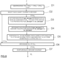
- the decoding method according to the invention is represented in the form of an algorithm comprising steps D1 to D7 as represented in figure 8 .
- the decoding method according to the invention is implemented in a decoding device or decoder DO represented in Figure 9 .
- the decoder DO comprises a memory MEM_DO which itself comprises a buffer memory TAMP_DO, a processing unit UT_DO equipped for example with a microprocessor ⁇ P and controlled by a computer program PG_DO which implements the decoding method according to the invention.
- the code instructions of the computer program PG_DO are for example loaded into a RAM memory before being executed by the processor of the processing unit UT_DO.
- the decoding process shown on the figure 8 applies to a data signal representative of a current fixed image IC j to be decoded or of a sequence of images to be decoded.
- information representative of the current image IC j to be decoded is identified in the data signal F received at the decoder DO, as delivered following the coding method of the Figure 3 .
- the quantified blocks CTUq 1 , CTUq 2 , ..., CTUq u , ..., CTUqs (1 ⁇ u ⁇ S) associated respectively are identified in the signal F to the blocks CTU 1 , CTU 2 , ..., CTU u , ..., CTUs previously coded in accordance with the aforementioned lexicographic order, according to the coding method of the Figure 3 .
- Such an identification step is implemented by a processor or MI_DO identification software module for flow analysis, as represented in Figure 9 , said module being controlled by the microprocessor ⁇ P of the processing unit UT_DO.
- each of the blocks to be decoded CTU 1 , CTU 2 , ..., CTU u , ..., CTUs has a square shape and comprises NxN pixels, with N ⁇ 2.
- each of the blocks to be decoded CTU 1 , CTU 2 , ..., CTU u , ..., CTUs has a rectangular shape and comprises NxP pixels, with N ⁇ 1 and P ⁇ 2.
- the DO decoder of the Figure 9 selects as current block the first quantized block CTUq u which contains quantized data which was encoded during step C6 of the Figure 3 .
- step D3 in association with the quantized block CTUq u which has been selected, the compressed value of the cutting_type syntax element which has been selected at the end of step C4 of the Figure 3 and, if applicable, to the compressed value of the arr_decoupe1 or arr_decoupe2 syntax element associated with it.
- the reading step D3 is carried out by a processor or reading software module ML_DO, as shown in Figure 9 , which module is controlled by the microprocessor ⁇ P of the processing unit UT_DO.
- step D4 represented in figure 8
- the value of the type_decoupe syntax element which was read in the aforementioned step D3 is decoded and, if necessary, the value of the syntax element arr_decoupe1 or arr_decoupe2 is decoded which is associated with it.
- step D4 is implemented by a processor or MDI indicator decoding software module as represented in Figure 9 , which module is controlled by the microprocessor ⁇ P of the processing unit UT_DO.
- the subdivision step D5 is carried out by a processor or partitioning software module MP_DO, as represented in Figure 9 , which module is controlled by the microprocessor ⁇ P of the processing unit UT_DO.
- the parts CU 1 and CU 2 of the current block CTU u to be decoded are decoded according to a predetermined travel order.
- the first part CU 1 is decoded before the second part CU 2 .
- the first part CU 1 is decoded after the second part CU 2 .
- the decoding step D6 is implemented by a processor or decoding software module UDO as shown in the Figure 9 , which module is controlled by the microprocessor ⁇ P of the processing unit UT_DO.
- step D6 a current decoded block CTUD u is obtained.
- step D7 represented in figure 8 , said decoded block CTUD u is written in a decoded image ID j .
- Such a step is implemented by a processor or URI software module for image reconstruction as shown in the Figure 9 , said module being controlled by the microprocessor ⁇ P of the processing module UT_DO.
- the data signal F contains the following three values 113, in the case where the type_cut indicator of value 3 associated with the coded data of the second part CU 2 has not been entered in the signal of data F, taking into account the fact that the second part CU 2 defines a homogeneous zone of the current block CTU u .
- the type_cut indicator is systematically set to the predetermined value 3, so that the second part CU 2 is not subdivided during decoding.
- Such an entropic decoding sub-step D611 is implemented by the entropic decoding module MDE_DO represented on the Figure 9 .
- the information relating to the predictive coding of the part CU 1 is also decoded as implemented in the sub-step C611 of the Figure 6A , and which have been recorded in the data signal F.
- Such reconstruction information includes in particular the type of prediction (inter or intra), and where applicable, the intra prediction mode or the reference image index and the displacement vector used in the inter prediction mode.
- substep D612 represented in Figure 10A , the digital information obtained following of substep D611, according to a classic dequantization operation which is the inverse operation of the quantification implemented during quantification substep C614 of the Figure 6A .
- a set of current dequantized coefficients CUDq 1 is then obtained at the end of substep D612.
- Such a substep D612 is carried out by means of the dequantization module MQ -1 _DO, as represented in Figure 9 .
- a transformation is carried out of the set of current dequantized coefficients CUDq 1 , such a transformation being a direct inverse transformation, such as for example an inverse discrete cosine transformation of the DCT -1 type.
- This transformation is the inverse operation of the transformation carried out in substep C613 of the Figure 6A .
- a decoded residue part CUDri is obtained. Such an operation is carried out by the MT -1 _DO module represented on the Figure 9 .
- the PRED -1 _DO module of the Figure 9 proceeds with the predictive decoding of the current part CU 1 using the information relating to the predictive coding of the part CU 1 which was decoded during the aforementioned substep D611.
- Said aforementioned predictive decoding sub-step makes it possible to construct a predicted part CUDp 1 which is an approximation of the current part CU 1 to be decoded.
- the CAL2_DO module of the Figure 9 proceeds to reconstruct the current part CU 1 by adding to the decoded residue part CUDri, obtained at the end of substep D613, the predicted part CUDp 1 which was obtained at the end of substep D614 aforementioned.
- the aforementioned substeps D610 to D615 are then iterated with a view to decoding the second part CU 2 alongside the current block CTU u .
- one or more reconstruction information of the pixels of the second part CU 2 are set to predetermined values.
- the pixels of the part CU 2 to be decoded are predicted with respect to pixels of corresponding predetermined values respectively.
- Such values are stored in a list LP contained in the TAMP_DO buffer of the DO decoder of the Figure 9 .
- substep D610 of the Figure 10A is not implemented since no set of quantized coefficients associated with the m-sided part CU 2 was transmitted in the data signal F.
- the quantized coefficients of the quantized residue part CUq 2 are then all directly put to zero by the UDO decoding module of the Figure 9 .
- the aforementioned substep D611 is not implemented in its entirety, the decoder DO deducing directly following the aforementioned substep D610 predetermined values of reconstruction information associated with the residue part CUr 2 .
- the pixels of the CU 2 part to be decoded are predicted conventionally, in the same way as the CU 1 part.
- an intermediate step D6110 is implemented between the aforementioned sub-steps D611 and D612.
- the decoded pixel values which were obtained following the entropic decoding step of the plurality of digital information associated with the set of current quantized coefficients CUq 2 are supplemented by values of predetermined pixels, until a square or rectangular block of pixel values is obtained.
- the aforementioned sub-step D6110 is implemented by a calculation software module CAL1_DO as represented in Figure 9 , which module is controlled by the microprocessor ⁇ P of the processing unit UT_DO.
- substep D6110 Taking into account the fact that substep D6110 only applies to the decoded pixel values which were obtained following the entropic decoding step of the plurality of digital information associated with the set of quantized coefficients CUq 2 current of geometric shape with m sides, this step, as well as the calculation module CAL1_DO, are represented in dotted lines, respectively on the figures 10A And 9 .
- This second embodiment differs from that of the Figure 10A by the fact that the first part CU 1 to be decoded from the current block CTU u is subdivided again.
- the data signal F contains the partitioning indicators of a current block CTU u which has been coded according to the embodiment of the Figure 6B .
- the signal F contains the following fifteen values 11 3 032603 3 33333 as represented in Figure 7 and which were decoded at the end of the aforementioned step D4.
- the type_cut indicator is systematically set to the predetermined value 3, so that neither the second part CU 2 of the current block CTU u to be decoded, nor the second part CU22 1 to m sides of the block CU2 1 of the block current CTU u to be decoded, is not subdivided during decoding.
- the decoding module UDO tests whether the index k associated with the current part CU k to be decoded is 1 or 2.
- the part CU 2 of the current block CTU u to be decoded is decoded according to substeps D610 to D615 of the Figure 10A .
- the UDO decoding module of the Figure 9 selects a current sub-part CU k' to be decoded of the first part CU 1 of the current block CTU u to be decoded, such that 1 ⁇ k' ⁇ N.
- N 8 since the first part CU 1 of the current block CTU u has been subdivided into eight “coding unit” type sub-parts CU1 1 , CU21 1 , CU22 1 , CU31 1 , CU32 1 , CU33 1 , CU34 1 , CU4 1 .
- the entropic decoding module MDE_DO of the Figure 9 also carries out an entropic decoding of the indicator I PR representative of the inter or intra prediction mode which has been selected for this current sub-part CU k' during sub-step C623 of the Figure 6B .
- the reading software module ML_DO of the Figure 9 proceeds to read the compressed value of the indicator representative of such a subdivision.
- Such an indicator consists of the decoupe_type syntax element and, if applicable, the arr_decoupe1 or arr_decoupe2 syntax element associated with it.
- the MDI indicator decoding software module of the Figure 9 proceeds to decode the value of the syntax element type_decoupe which was read in the aforementioned substep D624 and, if necessary, to decode the value of the syntax element arr_decoupe1 or arr_decoupe2 which is associated.
- the MP_DO partitioning software module of the Figure 9 subdivides the current sub-part CU k' to be decoded into a plurality W of prediction sub-parts PU 1 , PU 2 , ..., PU z , ..., PUw (1 ⁇ z ⁇ W).
- the UDO decoding module of the Figure 9 selects a first current subpart PU z . Such a selection is carried out in a predefined order, such as for example lexicographic order.
- the entropic decoding module MDE_DO of the Figure 9 proceeds, in association with the current sub-part PU z , to an entropic decoding of the optimal prediction parameters which were selected during sub-step C626 of the Figure 6B , in association with the indicator I PR which is representative of the prediction mode selected in the aforementioned substep C623 and which was decoded in substep D623.
- the optimal prediction parameters decoded are one or more motion vectors, as well as one or more reference images.
- the optimal prediction parameters are associated with an INTRA mode selected from different INTRA modes available.
- Substeps D627 to D628 are iterated for each of the subparts PU 1 , PU 2 , ..., PU z , ..., PUw of the current subpart CU k' to be decoded of the first part CU 1 of the current block CTU u , in the predetermined lexicographic order.
- the reading software module ML_DO of the Figure 9 proceeds to read the compressed value of the indicator representative of such a subdivision.
- Such an indicator consists of the decoupe_type syntax element and, if applicable, the arr_decoupe1 or arr_decoupe2 syntax element associated with it.
- the MDI indicator decoding software module of the Figure 9 proceeds to decode the value of the type_decoupe syntax element which was read in the aforementioned substep D629 and, if necessary, to decode the value of the arr_decoupe1 or arr_decoupe2 syntax element which is associated.
- the MP_DO partitioning software module of the Figure 9 subdivides the current sub-part CU k' to be decoded into a plurality Z of transform sub-parts TU 1 , TU 2 , ..., TU w , ..., TUz (1 ⁇ w ⁇ Z).
- the UDO decoding module of the Figure 9 selects the set of quantized coefficients TUq w current associated with the first sub-part of current transform TU w . Such a selection is carried out in a predefined order, such as for example lexicographic order.
- the MQ -1 _DO dequantization module of the Figure 9 proceeds with the dequantization of the digital information obtained following sub-step D633, according to a classic dequantization operation which is the reverse operation of the quantification implemented during the quantification sub-step C631 of the Figure 6B .
- a set of current dequantized coefficients TUDq w is then obtained at the end of substep D634.
- the MT -1 _DO module of the Figure 9 carries out a transformation of the set of current dequantized coefficients TUDq w , such a transformation being a direct inverse transformation, such as for example an inverse discrete cosine transformation of the DCT -1 type.
- This transformation is the inverse operation of the transformation carried out in substep C630 of the Figure 6A .
- a decoded residue part TUDr w is obtained.
- the PRED -1 _DO module of the Figure 9 proceeds with the predictive decoding of the first current transform sub-part TU w using the optimal prediction parameters which were read during the aforementioned sub-step D628.
- Said aforementioned predictive decoding sub-step makes it possible to construct a first current predicted transform sub-part TUDp w which is an approximation of the first current transform sub-part TU w to be decoded.
- the CAL2_DO module of the Figure 9 proceeds to reconstruct the first current transform sub-part TU w by adding to the decoded residue part TUDr w , obtained at the end of sub-step D635, the predicted part TUDp w which was obtained at the end of the aforementioned substep D636.
- All of the sub-steps D632 to D637 are iterated for each of the sub-parts TU 1 , TU 2 , ..., TU w , ..., TUz to be decoded from the sub-part CU k' current to be decoded from the first part CU 1 of the current block CTU u , in the predetermined lexicographic order.
- an intermediate sub-step D6330 is implemented between the aforementioned sub-steps D633 and D634.
- the values of decoded pixels which were obtained following sub-step D633 of entropic decoding of the plurality of digital information associated with the set of current quantized coefficients TUq w are completed by predetermined pixel values, until a square or rectangular block of pixel values is obtained.
- the aforementioned substep D6330 is implemented by the calculation software module CAL1_DO as represented in Figure 9 .
- All of the sub-steps D622 to D637 are iterated for each of the sub-parts CU 1 , CU 2 , ..., CU k' , ..., CU N to be decoded from the first current part CU 1 of the current block CTU u , in predetermined lexicographic order.
Abstract
Procédé de décodage d'un signal de données (F) représentatif d'au moins une image codée ayant été subdivisée en une pluralité de blocs (CTU<sub>1</sub>, CTU<sub>2</sub>, ..., CTU<sub>i</sub>, ..., CTU<sub>S</sub>), comprenant les étapes suivantes, pour un bloc courant à décoder, subdivisé en une première partie (CU<sub>1</sub>) et une deuxième partie (CU<sub>2</sub>), la première partie étant non subdivisible et ayant une forme rectangulaire ou carrée et la deuxième partie formant le complément de la première partie dans le bloc courant, ladite deuxième partie ayant une forme géométrique à m côtés, avec M>4 :- sélectionner, dans le signal de données, des données codées de la première partie,- décoder les données codées de la première partie,- reconstruire la première partie à partir des données décodées de la première partie,- reconstruire la deuxième partie en mettant à zéro des coefficients quantifiés issus d'une quantification d'un résidu de prédiction associé à ladite deuxième partie, lesdits coefficients quantifiés n'étant pas inscrits dans ledit signal de données.Method for decoding a data signal (F) representative of at least one coded image having been subdivided into a plurality of blocks (CTU<sub>1</sub>, CTU<sub>2</sub>,. .., CTU<sub>i</sub>, ..., CTU<sub>S</sub>), comprising the following steps, for a current block to be decoded, subdivided into a first part (CU<sub> 1</sub>) and a second part (CU<sub>2</sub>), the first part being non-subdivisible and having a rectangular or square shape and the second part forming the complement of the first part in the current block , said second part having a geometric shape with m sides, with M>4: - select, in the data signal, coded data of the first part, - decode the coded data of the first part, - reconstruct the first part to from the decoded data of the first part, - reconstruct the second part by setting to zero quantized coefficients resulting from a quantification of a prediction residue associated with said second part, said quantized coefficients not being registered in said signal of data.
Description
La présente invention se rapporte de manière générale au domaine du traitement d'images, et plus précisément au décodage d'images numériques et de séquences d'images numériques.The present invention relates generally to the field of image processing, and more specifically to the decoding of digital images and digital image sequences.
L'invention peut s'appliquer notamment, mais non exclusivement, au codage vidéo mis en oeuvre dans les codeurs vidéo actuels AVC et HEVC et leurs extensions (MVC, 3D-AVC, MV-HEVC, 3D-HEVC, etc), ainsi qu'au décodage correspondant.The invention can be applied in particular, but not exclusively, to video coding implemented in current AVC and HEVC video encoders and their extensions (MVC, 3D-AVC, MV-HEVC, 3D-HEVC, etc.), as well as 'to the corresponding decoding.
Les codeurs vidéo actuels (MPEG, H.264, HEVC, ...) utilisent une représentation par blocs des images à coder. Les images sont subdivisées en blocs de forme carrée ou rectangulaire, lesquels sont susceptibles d'être subdivisés à leur tour de façon récursive. Dans la norme HEVC, une telle subdivision récursive respecte une structure arborescente appelée « quadtree ». A cet effet, comme représenté sur la
Pour un bloc CTUi donné, il est considéré que ce bloc constitue la racine d'un arbre de codage dans lequel :
- un premier niveau de feuilles sous la racine correspond à un premier niveau de profondeur de subdivision du bloc CTUi pour lequel le bloc CTUi a été subdivisé une première fois en une pluralité de blocs de codage carrés ou rectangulaires appelés CU (de l'anglais « Coding Unit »),
- un deuxième niveau de feuilles sous le premier niveau de feuilles correspond à un deuxième niveau de profondeur de partitionnement de bloc CTUi pour lequel certains blocs de ladite pluralité de blocs de codage du bloc partitionné une première fois sont partitionnés en une pluralité de blocs de codage de type CU, ...
- ... un kième niveau de feuilles sous le k-1 ième niveau de feuilles qui correspond à un kième niveau de profondeur de partitionnement du bloc CTUi pour lequel certains blocs de ladite pluralité de blocs de codage du bloc partitionné k-1 fois sont partitionnés une dernière fois en une pluralité de blocs de codage de type CU.
- a first level of leaves under the root corresponds to a first level of depth of subdivision of the CTUi block for which the CTUi block has been subdivided a first time into a plurality of square or rectangular coding blocks called CU (from the English “Coding Unit"),
- a second level of sheets below the first level of sheets corresponds to a second level of block partitioning depth CTUi for which certain blocks of said plurality of coding blocks of the block partitioned a first time are partitioned into a plurality of CU type coding blocks, ...
- ... a kth level of leaves below the k-1th level of leaves which corresponds to a kth level of partitioning depth of the CTUi block for which certain blocks of said plurality of coding blocks of the k-1 times partitioned block are partitioned one last time in a plurality of CU type coding blocks.
Dans un codeur compatible HEVC, l'itération du partitionnement du bloc CTUi est effectuée jusqu'à un niveau de profondeur de partitionnement prédéterminé.In an HEVC compatible encoder, the partitioning iteration of the CTUi block is performed up to a predetermined partitioning depth level.
A l'issue des partitionnements successifs précités du bloc CTUi, comme représenté à la
Le but d'une telle subdivision est de délimiter des zones qui s'adaptent bien aux caractéristiques locales de l'image, telles que par exemple une texture homogène, un mouvement constant, un objet en avant plan dans l'image, etc...The aim of such a subdivision is to delimit areas which adapt well to the local characteristics of the image, such as for example a homogeneous texture, constant movement, a foreground object in the image, etc. .
Pour un bloc CTUi considéré, plusieurs subdivisions différentes de ce dernier sont mises en compétition au codeur, c'est-à-dire respectivement différentes combinaisons d'itérations de subdivision, dans le but de sélectionner la meilleure subdivision, c'est-à-dire celle qui optimise le codage du bloc CTUi considéré selon un critère de performance de codage prédéterminé, par exemple le coût débit/distorsion ou bien un compromis efficacité/complexité, qui sont des critères bien connus de l'homme du métier.For a CTUi block considered, several different subdivisions of the latter are put into competition with the encoder, that is to say respectively different combinations of subdivision iterations, with the aim of selecting the best subdivision, that is to say say that which optimizes the coding of the CTUi block considered according to a predetermined coding performance criterion, for example the throughput/distortion cost or an efficiency/complexity compromise, which are criteria well known to those skilled in the art.
Une fois réalisée la subdivision optimale d'un bloc CTUi considéré, une séquence d'informations numériques, telle que par exemple une suite de bits, représentative de cette subdivision optimale, est transmise dans un signal de données destiné à être stocké au codeur ou bien transmis à un décodeur vidéo pour être lu, puis décodé par ce dernier.Once the optimal subdivision of a CTUi block considered has been achieved, a sequence of digital information, such as for example a series of bits, representative of this optimal subdivision, is transmitted in a data signal intended to be stored in the encoder or else transmitted to a video decoder for playback, then decoded by the latter.
Dans l'exemple de la
- le premier bit « 1 » indique une subdivision du bloc CTUi en quatre sous-blocs plus petits UC1, UC2, UC3, UC4,
- le deuxième bit « 1 » indique une subdivision du sous-bloc UC1 en quatre sous-blocs plus petits UC5, UC6, UC7, UC8,
- le troisième bit « 0 » indique une absence de subdivision du sous-bloc UC2,
- le quatrième bit « 0 » indique une absence de subdivision du sous-bloc UC3,
- le cinquième bit « 0 » indique une absence de subdivision du sous-bloc UC4,
- le sixième bit « 0 » indique une absence de subdivision du sous-bloc UC5,
- le septième bit « 1 » indique une subdivision du sous-bloc UC6 en quatre sous-blocs plus petits UC9, UC10, UC11, UC12,
- le huitième bit « 1 » indique une subdivision du sous-bloc UC7 en quatre sous-blocs plus petits UC13, UC14, UC15, UC16,
- le neuvième bit « 0 » indique une absence de subdivision du sous-bloc UC8,
- le dixième bit « 0 » indique une absence de subdivision du sous-bloc UC9,
- le onzième bit « 0 » indique une absence de subdivision du sous-bloc UC10,
- le douzième bit « 0 » indique une absence de subdivision du sous-bloc UC11,
- le treizième bit « 0 » indique une absence de subdivision du sous-bloc UC12,
- le quatorzième bit « 0 » indique une absence de subdivision du sous-bloc UC13,
- le quinzième bit « 0 » indique une absence de subdivision du sous-bloc UC14,
- le seizième bit « 0 » indique une absence de subdivision du sous-bloc UC15,
- le dix-septième bit « 0 » indique une absence de subdivision du sous-bloc UC16.
- the first bit “1” indicates a subdivision of the CTUi block into four smaller sub-blocks UC 1 , UC 2 , UC 3 , UC 4 ,
- the second bit “1” indicates a subdivision of the sub-block UC 1 into four smaller sub-blocks UC 5 , UC 6 , UC 7 , UC 8 ,
- the third bit “0” indicates an absence of subdivision of the CPU 2 sub-block,
- the fourth bit “0” indicates an absence of subdivision of the CPU sub-block 3 ,
- the fifth bit “0” indicates an absence of subdivision of the CPU sub-block 4 ,
- the sixth bit “0” indicates an absence of subdivision of the CPU sub-block 5 ,
- the seventh bit “1” indicates a subdivision of the sub-block UC 6 into four smaller sub-blocks UC 9 , UC 10 , UC 11 , UC 12 ,
- the eighth bit “1” indicates a subdivision of the sub-block UC 7 into four smaller sub-blocks UC 13 , UC 14 , UC 15 , UC 16 ,
- the ninth bit “0” indicates an absence of subdivision of the CPU sub-block 8 ,
- the tenth bit “0” indicates an absence of subdivision of the UC 9 sub-block,
- the eleventh bit “0” indicates an absence of subdivision of the UC 10 sub-block,
- the twelfth bit “0” indicates an absence of subdivision of the CPU sub-block 11 ,
- the thirteenth bit “0” indicates an absence of subdivision of the CPU sub-block 12 ,
- the fourteenth bit “0” indicates an absence of subdivision of the CPU sub-block 13 ,
- the fifteenth bit “0” indicates an absence of subdivision of the UC sub-block 14 ,
- the sixteenth bit “0” indicates an absence of subdivision of the UC sub-block 15 ,
- the seventeenth bit “0” indicates an absence of subdivision of the CPU subblock 16 .
La séquence binaire obtenue nécessite qu'un ordre de parcours des sous-blocs soit prédéterminé afin de savoir à quel sous-bloc correspond un élément de syntaxe indicateur de la subdivision effectuée. Comme représenté par la flèche F sur la
- les sous-blocs sont parcourus en commençant par le premier sous-bloc UC1 situé en haut à gauche du bloc CTUi et ainsi de suite jusqu'à parvenir au sous-bloc UC4 situé en bas à droite du bloc CTUi,
- les sous-blocs résultant de la subdivision du sous-bloc UC6 sont parcourus en commençant par le premier sous-bloc UC9 situé en haut à gauche du sous-bloc UC6 et ainsi de suite jusqu'à parvenir au sous-bloc UC12 situé en bas à droite du sous-bloc UC6,
- les sous-blocs résultant de la subdivision du sous-bloc UC7 sont parcourus en commençant par le premier sous-bloc UC13 situé en haut à gauche du sous-bloc UC7 et ainsi de suite jusqu'à parvenir au sous-bloc UC16 situé en bas à droite du sous-bloc UC7.
- the sub-blocks are traversed starting with the first UC 1 sub-block located at the top left of the CTUi block and so on until reaching the UC 4 sub-block located at the bottom right of the CTU i block,
- the sub-blocks resulting from the subdivision of the UC sub-block 6 are traversed starting with the first UC sub-block 9 located at the top left of the UC sub-block 6 and so on until reaching the UC sub-block 12 located at the bottom right of the UC 6 sub-block,
- the sub-blocks resulting from the subdivision of the UC sub-block 7 are traversed starting with the first UC sub-block 13 located at the top left of the UC sub-block 7 and so on until reaching the UC sub-block 16 located at the bottom right of the UC 7 sub-block.
Les dix-sept bits précités sont inscrits les uns à la suite des autres dans la séquence binaire qui est ensuite compressée par un codage entropique adapté.The seventeen aforementioned bits are written one after the other in the binary sequence which is then compressed by a suitable entropic coding.
Pour au moins un sous-bloc considéré parmi les différents sous-blocs obtenus, une prédiction de pixels du sous-bloc considéré est mise en oeuvre par rapport à des pixels de prédiction qui appartiennent soit à la même image (prédiction intra), soit à une ou plusieurs images précédentes d'une séquence d'images (prédiction inter) qui ont déjà été décodées. De telles images précédentes sont appelées classiquement images de référence et sont conservées en mémoire aussi bien au codeur qu'au décodeur. Au cours d'une telle prédiction, un sous-bloc résiduel est calculé par soustraction des pixels du sous-bloc considéré, des pixels de prédiction. Les coefficients du sous-bloc résiduel calculé sont alors quantifiés après une éventuelle transformation mathématique, par exemple de type transformée en cosinus discrète (DCT), puis codés par un codeur entropique.For at least one sub-block considered among the different sub-blocks obtained, a prediction of pixels of the sub-block considered is implemented in relation to prediction pixels which belong either to the same image (intra prediction), or to one or more previous images of a sequence of images (inter prediction) which have already been decoded. Such previous images are conventionally called reference images and are stored in memory both at the encoder and at the decoder. During such a prediction, a residual sub-block is calculated by subtracting the pixels of the sub-block considered from the prediction pixels. The coefficients of the calculated residual sub-block are then quantified after a possible mathematical transformation, for example of the discrete cosine transform (DCT) type, then coded by an entropic encoder.
Le choix entre mode de prédiction inter ou intra se fait au niveau de chacun des sous-blocs UC1, UC2, ..., UCj, ..., UCM qui peuvent eux-même être partitionnés en sous-blocs de prédiction (« Prédiction Units » en anglais) et en sous-blocs de transformée (« Transform Units » en anglais). Chacun des sous-blocs de prédiction et des sous-blocs de transformée sont à leur tour susceptibles d'être subdivisés récursivement en sous-blocs selon la structure arborescente « quadtree » précitée.The choice between inter or intra prediction mode is made at the level of each of the sub-blocks UC 1 , UC 2 , ..., UC j , ..., UC M which can themselves be partitioned into prediction sub-blocks (“Prediction Units” in English) and transform sub-blocks (“Transform Units” in English). Each of the prediction sub-blocks and the transform sub-blocks are in turn capable of being subdivided recursively into sub-blocks according to the aforementioned “quadtree” tree structure.
Le bloc CTUi ainsi que ses sous-blocs UC1, UC2, ..., UCj, ..., UCM, ses sous-blocs de prédiction et ses sous-blocs de transformée, sont susceptibles d'être associés à des informations décrivant leur contenu.The CTUi block as well as its sub-blocks UC 1 , UC 2 , ..., UC j , ..., UC M , its prediction sub-blocks and its transform sub-blocks, are likely to be associated with information describing their content.
De telles informations sont notamment les suivantes :
- le mode de prédiction (prédiction intra, prédiction inter, prédiction par défaut réalisant une prédiction pour laquelle aucune information n'est transmise au décodeur (« en anglais « skip »)) ;
- le type de prédiction (orientation, composante d'image de référence, ...) ;
- le type de subdivision en sous-blocs ;
- le type de transformée, par exemple DCT 4x4, DCT 8x8, etc... ;
- les valeurs de pixels, les valeurs de coefficients transformés, amplitudes, signes de coefficients quantifiés des pixels contenus dans le bloc ou le sous-bloc considéré.
- the prediction mode (intra prediction, inter prediction, default prediction carrying out a prediction for which no information is transmitted to the decoder (“skip”));
- the type of prediction (orientation, reference image component, etc.);
- the type of subdivision into sub-blocks;
- the type of transform, for example DCT 4x4, DCT 8x8, etc...;
- the pixel values, the values of transformed coefficients, amplitudes, signs of quantized coefficients of the pixels contained in the block or sub-block considered.
Ces informations sont également inscrites dans le signal de données précité.This information is also recorded in the aforementioned data signal.
Lors du codage d'une image fixe ou d'une image d'une séquence d'images utilisant une subdivision en sous-blocs de type quadtree, il est courant de retrouver dans l'image un objet significatif de taille moyenne ou petite qui est situé dans une zone de l'image relativement homogène. Une telle configuration est par exemple représentée sur la
Après mise en oeuvre d'une subdivision en blocs et en sous-blocs de type quadtree comme représenté sur la
Un inconvénient d'une telle subdivision est qu'elle nécessite la transmission d'une séquence binaire représentative de cette subdivision qui contient un nombre de bits non négligeable. Une telle séquence s'avère coûteuse à signaler, ce qui ne permet pas d'optimiser la réduction du gain en compression des données codées. Il en résulte des performances de compression qui ne sont pas satisfaisantes.A disadvantage of such a subdivision is that it requires the transmission of a binary sequence representative of this subdivision which contains a non-negligible number of bits. Such a sequence proves costly to signal, which does not make it possible to optimize the reduction of the compression gain of the coded data. This results in compression performance that is not satisfactory.
Un des buts de l'invention est de remédier à des inconvénients de l'état de la technique précité.One of the aims of the invention is to remedy the drawbacks of the aforementioned state of the art.
A cet effet, l'invention concerne un procédé de décodage d'un signal de données représentatif d'au moins une image codée ayant été subdivisée en une pluralité de blocs.To this end, the invention relates to a method for decoding a data signal representative of at least one coded image having been subdivided into a plurality of blocks.
Un tel procédé de décodage est remarquable en ce qu'il comprend les étapes suivantes, pour un bloc courant à décoder, subdivisé en une première partie et une deuxième partie, la première partie étant non subdivisible et ayant une forme rectangulaire ou carrée et la deuxième partie formant le complément de la première partie dans le bloc courant, ladite deuxième partie ayant une forme géométrique à m côtés, avec m>4 :
- sélectionner, dans le signal de données, des données codées de la première partie,
- décoder les données codées de la première partie,
- reconstruire la première partie à partir des données décodées de la première partie,
- reconstruire la deuxième partie en mettant à zéro des coefficients quantifiés issus d'une quantification d'un résidu de prédiction associé à ladite deuxième partie, lesdits coefficients quantifiés n'étant pas inscrits dans ledit signal de données.
- select, in the data signal, coded data from the first part,
- decode the coded data of the first part,
- reconstruct the first part from the decoded data of the first part,
- reconstructing the second part by setting to zero quantized coefficients resulting from a quantification of a prediction residue associated with said second part, said quantized coefficients not being recorded in said data signal.
Une telle disposition permet de subdiviser très simplement un bloc courant à décoder en seulement deux parties, une telle subdivision étant beaucoup moins complexe à effectuer qu'une subdivision de type « quadtree ».Such an arrangement makes it possible to very simply subdivide a current block to be decoded into only two parts, such a subdivision being much less complex to carry out than a “quadtree” type subdivision.
Par ailleurs, la subdivision selon l'invention est particulièrement bien adaptée au cas où des blocs de l'image à décoder contiennent un élément significatif, par exemple un objet en avant-plan, qui est situé dans une zone homogène présentant une énergie faible, telle que par exemple un arrière-plan de couleur, orientation ou mouvement uniforme.Furthermore, the subdivision according to the invention is particularly well suited to the case where blocks of the image to be decoded contain an element significant, for example a foreground object, which is located in a homogeneous area having low energy, such as for example a background of uniform color, orientation or movement.
Dans un mode de réalisation particulier, le procédé de décodage comprend en outre un décodage, en association avec les données décodées de la première partie, d'une valeur d'un élément de syntaxe lu dans le signal de données, ladite valeur correspondant à une prédiction Intra ou Inter à appliquer à la première partie.In a particular embodiment, the decoding method further comprises decoding, in association with the decoded data of the first part, of a value of a syntax element read in the data signal, said value corresponding to a Intra or Inter prediction to apply to the first part.
Dans un mode de réalisation particulier, au cours de la reconstruction de la deuxième partie à m côtés du bloc courant, au moins une information de reconstruction des pixels de la deuxième partie à m côtés du bloc courant est mise à une valeur prédéterminée.In a particular embodiment, during the reconstruction of the second part at m sides of the current block, at least one reconstruction information of the pixels of the second part at m sides of the current block is set to a predetermined value.
Un avantage d'une telle disposition réside dans le fait que le décodeur détermine de façon autonome ladite au moins une information de reconstruction des pixels de la deuxième partie à m côtés. Autrement dit, ladite au moins une information de reconstruction correspondante n'est avantageusement pas transmise dans le signal de données reçu au décodeur. Ainsi la réduction du coût de signalisation est optimisée.An advantage of such an arrangement lies in the fact that the decoder autonomously determines said at least one piece of information for reconstructing the pixels of the second part with m sides. In other words, said at least one piece of corresponding reconstruction information is advantageously not transmitted in the data signal received at the decoder. Thus the reduction in signaling cost is optimized.
Selon une variante, ladite au moins une information de reconstruction des pixels de la deuxième partie à m côtés du bloc courant est représentative de l'absence de subdivision de la deuxième partie à m côtés du bloc courant.According to a variant, said at least one piece of information for reconstructing the pixels of the second part at m sides of the current block is representative of the absence of subdivision of the second part at m sides of the current block.
De façon avantageuse, au moment de décoder la deuxième partie à m côtés du bloc courant, le décodeur détermine de façon autonome qu'il n'a pas besoin de subdiviser cette partie, puisqu'elle caractérise une région homogène du bloc courant à décoder qui est dépourvue de détails.Advantageously, when decoding the second part to m sides of the current block, the decoder determines autonomously that it does not need to subdivide this part, since it characterizes a homogeneous region of the current block to be decoded which is devoid of details.
Selon une autre variante, ladite au moins une information de reconstruction des pixels de la deuxième partie à m côtés du bloc courant est représentative de l'absence d'informations résiduelles résultant d'une prédiction des pixels de la deuxième partie à m côtés du bloc courant.According to another variant, said at least one reconstruction information of the pixels of the second part at m sides of the current block is representative of the absence of residual information resulting from a prediction of the pixels of the second part at m sides of the block fluent.
De façon avantageuse, au moment de décoder la deuxième partie à m côtés du bloc courant, le décodeur détermine de façon autonome que les pixels résiduels obtenus suite à la prédiction de ladite deuxième partie à m côtés ont une valeur nulle. Il est considéré que la deuxième partie à m côtés est associée à un résidu de prédiction nul puisqu'elle caractérise une région homogène du bloc courant à décoder.Advantageously, when decoding the second part with m sides of the current block, the decoder determines autonomously that the residual pixels obtained following the prediction of said second part with m sides have a zero value. It is considered that the second part with m sides is associated to a zero prediction residual since it characterizes a homogeneous region of the current block to be decoded.
Selon encore une autre variante, ladite au moins une information de reconstruction des pixels de la deuxième partie à m côtés du bloc courant est représentative de valeurs de prédiction prédéterminées des pixels de la deuxième partie à m côtés du bloc courant.According to yet another variant, said at least one reconstruction information of the pixels of the second part at m sides of the current block is representative of predetermined prediction values of the pixels of the second part at m sides of the current block.
Une telle variante permet d'optimiser encore davantage le coût de signalisation en évitant de transmettre dans le signal de données l'indice du mode de prédiction qui a été sélectionné au codage pour prédire la deuxième partie à m côtés du bloc courant.Such a variant makes it possible to further optimize the signaling cost by avoiding transmitting in the data signal the index of the prediction mode which was selected during coding to predict the second part at m sides of the current block.
Dans encore un autre mode de réalisation particulier, un bloc courant subdivisé contient au plus une partie ayant une forme géométrique à m côtés.In yet another particular embodiment, a subdivided current block contains at most one part having a geometric shape with m sides.
Une telle disposition est bien adaptée au cas où le bloc courant contient deux zones de texture bien distinctes, c'est-à-dire celle définie par un seul élément significatif et celle définie par une seule zone homogène. De façon avantageuse, il n'est donc pas nécessaire de procéder à une nouvelle subdivision du bloc courant à décoder.Such an arrangement is well suited to the case where the current block contains two very distinct texture zones, that is to say that defined by a single significant element and that defined by a single homogeneous zone. Advantageously, it is therefore not necessary to carry out a new subdivision of the current block to be decoded.
Dans encore un autre mode de réalisation particulier, la première partie est située dans un des coins du bloc courant et m=6.In yet another particular embodiment, the first part is located in one of the corners of the current block and m=6.
Les différents modes ou caractéristiques de réalisation précités peuvent être ajoutés indépendamment ou en combinaison les uns avec les autres, aux étapes du procédé de décodage tel que défini ci-dessus.The various aforementioned embodiments or characteristics can be added independently or in combination with each other, to the stages of the decoding process as defined above.
Corrélativement, l'invention concerne un dispositif de décodage d'un signal de données représentatif d'au moins une image codée ayant été subdivisée en une pluralité de blocs.Correlatively, the invention relates to a device for decoding a data signal representative of at least one coded image having been subdivided into a plurality of blocks.
Un tel dispositif de décodage est remarquable en ce qu'il comprend, pour un bloc courant à décoder, subdivisé en une première partie et une deuxième partie, la première partie étant non subdivisible et ayant une forme rectangulaire ou carrée et la deuxième partie formant le complément de la première partie dans le bloc courant, ladite deuxième partie ayant une forme géométrique à m côtés, avec m>4 :
- des moyens de sélection, dans le signal de données, de données codées de la première partie,
- des moyens de décodage des données codées de la première partie,
- des moyens de reconstruction de la première partie à partir des données décodées de la première partie,
- des moyens de reconstruction de la deuxième partie en mettant à zéro des coefficients quantifiés issus d'une quantification d'un résidu de prédiction associé à ladite deuxième partie, lesdits coefficients quantifiés n'étant pas inscrits dans ledit signal de données.
- means for selecting, in the data signal, coded data from the first part,
- means for decoding the coded data of the first part,
- means for reconstructing the first part from the decoded data of the first part,
- means for reconstructing the second part by setting to zero quantized coefficients resulting from a quantification of a prediction residue associated with said second part, said quantized coefficients not being recorded in said data signal.
L'invention concerne encore un programme d'ordinateur comportant des instructions pour mettre en oeuvre le procédé de décodage selon l'invention, lorsqu'il est exécuté sur un ordinateur.The invention also relates to a computer program comprising instructions for implementing the decoding method according to the invention, when executed on a computer.
Un tel programme peut utiliser n'importe quel langage de programmation, et être sous la forme de code source, code objet, ou de code intermédiaire entre code source et code objet, tel que dans une forme partiellement compilée, ou dans n'importe quelle autre forme souhaitable.Such a program may use any programming language, and be in the form of source code, object code, or intermediate code between source code and object code, such as in a partially compiled form, or in any other desirable form.
Encore un autre objet de l'invention vise aussi un support d'enregistrement lisible par un ordinateur, et comportant des instructions de programme d'ordinateur tel que mentionné ci-dessus.Yet another object of the invention also targets a recording medium readable by a computer, and comprising computer program instructions as mentioned above.
Le support d'enregistrement peut être n'importe quelle entité ou dispositif capable de stocker le programme. Par exemple, le support peut comporter un moyen de stockage, tel qu'une ROM, par exemple un CD ROM ou une ROM de circuit microélectronique, ou encore un moyen d'enregistrement magnétique, par exemple une clé USB ou un disque dur.The recording medium can be any entity or device capable of storing the program. For example, the medium may comprise a storage means, such as a ROM, for example a CD ROM or a microelectronic circuit ROM, or even a magnetic recording means, for example a USB key or a hard disk.
D'autre part, un tel support d'enregistrement peut être un support transmissible tel qu'un signal électrique ou optique, qui peut être acheminé via un câble électrique ou optique, par radio ou par d'autres moyens. Le programme selon l'invention peut être en particulier téléchargé sur un réseau de type Internet.On the other hand, such a recording medium may be a transmissible medium such as an electrical or optical signal, which may be conveyed via an electrical or optical cable, by radio or by other means. The program according to the invention can in particular be downloaded onto an Internet type network.
Alternativement, un tel support d'enregistrement peut être un circuit intégré dans lequel le programme est incorporé, le circuit étant adapté pour exécuter le procédé en question ou pour être utilisé dans l'exécution de ce dernier.Alternatively, such a recording medium may be an integrated circuit in which the program is incorporated, the circuit being adapted to execute the method in question or to be used in the execution of the latter.
D'autres caractéristiques et avantages apparaîtront à la lecture de plusieurs modes de réalisation préférés décrits en référence aux figures dans lesquelles les aspects relatifs au codage ne relèvent pas de l'invention et ne sont présents qu'à titre illustratif, et dans lesquelles :
- la
figure 1 représente un exemple de subdivision classique d'un bloc courant, telle que la subdivision de type « quadtree », - les
figures 2A et 2B représentent une application de la subdivision de type « quadtree » à un bloc courant qui contient un seul élément significatif, une étoile, laquelle est contenue dans une zone homogène telle que par exemple un ciel de couleur uniforme, - la
figure 3 représente les principales étapes d'un procédé de codage, - la
figure 4 représente un exemple d'un dispositif de codage, - les
figures 5A à 5J représentent respectivement différents modes de réalisation de subdivision selon l'invention du bloc courant, - les
figures 6A et6B représentent respectivement deux exemples de codage des parties obtenues par subdivision du bloc courant, conformément à un type de subdivision représenté à lafigure 5A , - la
figure 7 représente un exemple de subdivision du bloc courant auquel s'applique le codage de lafigure 6B , - la
figure 8 représente les principales étapes du procédé de décodage selon un mode de réalisation de l'invention, - la
figure 9 représente un mode de réalisation d'un dispositif de décodage selon l'invention, - les
figures 10A et10B représentent respectivement deux modes de réalisation de décodage des parties obtenues après reconstruction de la subdivision du bloc courant, conformément à un type de subdivision représenté à lafigure 5A .
- there
figure 1 represents an example of classic subdivision of a current block, such as the “quadtree” type subdivision, - THE
Figures 2A and 2B represent an application of the “quadtree” type subdivision to a current block which contains a single significant element, a star, which is contained in a homogeneous zone such as for example a sky of uniform color, - there
Figure 3 represents the main stages of a coding process, - there
Figure 4 represents an example of a coding device, - THE
Figures 5A to 5J respectively represent different embodiments of subdivision according to the invention of the current block, - THE
figures 6A And6B respectively represent two examples of coding of the parts obtained by subdivision of the current block, in accordance with a type of subdivision represented infigure 5A , - there
Figure 7 represents an example of subdivision of the current block to which the coding of theFigure 6B , - there
figure 8 represents the main stages of the decoding process according to one embodiment of the invention, - there
Figure 9 represents an embodiment of a decoding device according to the invention, - THE
figures 10A And10B respectively represent two embodiments of decoding the parts obtained after reconstruction of the subdivision of the current block, in accordance with a type of subdivision represented infigure 5A .
Un mode de réalisation va maintenant être décrit, dans lequel un procédé de codage est utilisé pour coder une image ou une séquence d'images selon un signal binaire proche de celui qu'on obtient par un codage mis en oeuvre dans un codeur conforme à l'une quelconque des normes de codage vidéo actuelles ou à venir.An embodiment will now be described, in which an coding method is used to encode an image or a sequence of images according to a binary signal close to that obtained by coding implemented in an encoder conforming to any of the current or future video coding standards.
Dans ce mode de réalisation, le procédé de codage est par exemple implémenté de manière logicielle ou matérielle par modifications d'un tel codeur. Le procédé de codage est représenté sous la forme d'un algorithme comportant des étapes C1 à C7 telles que représentées à la
Selon ce mode de réalisation, le procédé de codage est implémenté dans un dispositif de codage ou codeur CO représenté à la
Comme illustré en
Le procédé de codage représenté sur la
Au cours d'une étape C1 représentée à la
Une telle étape de subdivision est mise en oeuvre par un processeur ou module logiciel de partitionnement MP_CO représenté sur la
De façon préférentielle, chacun des blocs CTU1, CTU2, ..., CTUu, ..., CTUs présente une forme carrée et comprend NxN pixels, avec N≥2.Preferably, each of the blocks CTU 1 , CTU 2 , ..., CTU u , ..., CTUs has a square shape and comprises NxN pixels, with N≥2.
Selon une alternative, chacun des blocs CTU1, CTU2, ..., CTUu, ..., CTUs présente une forme rectangulaire et comprend NxP pixels, avec N≥1 et P≥2.According to an alternative, each of the blocks CTU 1 , CTU 2 , ..., CTU u , ..., CTUs has a rectangular shape and comprises NxP pixels, with N≥1 and P≥2.
Au cours d'une étape C2 représentée à la
- la première partie a une forme rectangulaire ou carrée,
- et la deuxième partie a une forme géométrique à m côtés, avec m>4.
- the first part has a rectangular or square shape,
- and the second part has an m-sided geometric shape, with m>4.
Selon un mode préféré de réalisation, le bloc courant CTUu est subdivisé :
- en une première partie de forme rectangulaire ou carrée ou bien en une pluralité de parties de forme rectangulaire ou carrée,
- et en au plus une deuxième partie de forme géométrique à m côtés.
- in a first part of rectangular or square shape or in a plurality of parts of rectangular or square shape,
- and at most a second part of geometric shape with m sides.
Au sens de l'invention, les première et deuxième parties forment respectivement deux unités de codage (de l'anglais « coding unit ») distinctes CU1 et CU2. Cette dernière terminologie est notamment utilisée dans la norme HEVC « ISO/IEC/23008-2 Recommandation ITU-T H.265 High Efficiency Video Coding (HEVC) ».For the purposes of the invention, the first and second parts respectively form two distinct coding units CU 1 and CU 2 . This latter terminology is notably used in the HEVC standard “ISO/IEC/23008-2 ITU-T Recommendation H.265 High Efficiency Video Coding (HEVC)”.
Selon un premier mode de réalisation de subdivision représenté sur la
- la première partie CU1 est un bloc carré de taille

- et la deuxième partie CU2, qui forme le complément de la première partie CU1 dans le bloc courant CTUu, a une forme géométrique à m côtés, avec m>4.
- the first part CU 1 is a square block of size
- and the second part CU 2 , which forms the complement of the first part CU 1 in the current block CTU u , has a geometric shape with m sides, with m>4.
Dans l'exemple représenté sur la
Comme représenté sur la
Dans un souci de clarté de la
- le premier pixel ptIu du bloc courant CTUu, de coordonnées (xmin, ymin), qui est situé en haut et à gauche dans ce dernier,
- le dernier pixel pbru du bloc courant CTUu, de coordonnées (xmax, ymax), qui est situé en bas et à droite dans ce dernier,
- le premier pixel ptI1 de la première partie CU1, de coordonnées (x'min, y'min), qui est situé en haut et à gauche dans cette dernière,
- le dernier pixel pbri de la première partie CU1, de coordonnées (x'max, y'max) qui est situé en bas et à droite dans cette dernière.
- the first pixel ptI u of the current block CTU u , with coordinates (x min , y min ), which is located at the top and to the left in the latter,
- the last pixel pbr u of the current block CTU u , with coordinates (x max , y max ), which is located at the bottom and to the right in the latter,
- the first pixel ptI 1 of the first part CU 1 , with coordinates (x' min , y' min ), which is located at the top and to the left in the latter,
- the last pbri pixel of the first part CU 1 , with coordinates (x' max , y' max ) which is located at the bottom and to the right in the latter.
Selon le type particulier de subdivision SUB11, le premier pixel ptIu du bloc courant CTUu est le même que le premier pixel ptI1 de la première partie CU1.According to the particular type of subdivision SUB1 1 , the first pixel ptI u of the current block CTU u is the same as the first pixel ptI 1 of the first part CU 1 .
Quel que soit le type de subdivision choisi, la deuxième partie CU2 de forme géométrique à m côtés est alors définie de façon générale comme un ensemble de pixels ptI2 tel que pour tout pixel pv2(x"v, y"v) de cet ensemble :
Selon un deuxième mode de réalisation de subdivision représenté sur la
- la première partie CU1 est un bloc carré de taille

- et la deuxième partie CU2, qui forme le complément de la première partie CU1 dans le bloc courant CTUu, a une forme géométrique à m côtés, avec m>4.
- the first part CU 1 is a square block of size
- and the second part CU 2 , which forms the complement of the first part CU 1 in the current block CTU u , has a geometric shape with m sides, with m>4.
Dans l'exemple représenté sur la
Comme représenté sur la
Dans un souci de clarté de la
- le premier pixel ptIu du bloc courant CTUu, de coordonnées (xmin, ymin), qui est situé en haut et à gauche dans ce dernier,
- le dernier pixel pbru du bloc courant CTUu, de coordonnées (xmax, ymax), qui est situé en bas et à droite dans ce dernier,
- le premier pixel ptI1 de la première partie CU1, de coordonnées (x'min, y'min), qui est situé en haut et à gauche dans cette dernière,
- le dernier pixel pbri de la première partie CU1, de coordonnées (x'max, y'max) qui est situé en bas et à droite dans cette dernière.
- the first pixel ptI u of the current block CTU u , with coordinates (x min , y min ), which is located at the top and to the left in the latter,
- the last pixel pbr u of the current block CTU u , with coordinates (x max , y max ), which is located at the bottom and to the right in the latter,
- the first pixel ptI 1 of the first part CU 1 , with coordinates (x' min , y' min ), which is located at the top and to the left in the latter,
- the last pbri pixel of the first part CU 1 , with coordinates (x' max , y' max ) which is located at the bottom and to the right in the latter.
Selon le mode particulier de subdivision SUB12, le premier pixel ptIu du bloc courant CTUu est le même que le premier pixel ptI1 de la première partie CU1.According to the particular mode of subdivision SUB1 2 , the first pixel ptI u of the current block CTU u is the same as the first pixel ptI 1 of the first part CU 1 .
Quel que soit le type de subdivision choisi, la deuxième partie CU2 de forme géométrique à m côtés est alors définie de façon générale comme un ensemble de pixels tel que pour tout pixel pv2(x"v, y"v) de cet ensemble :
Selon des troisième, quatrième, cinquième et sixième modes de réalisation de subdivision représentés respectivement sur les
- la première partie CU1 est un bloc rectangulaire de taille UxV pixels, tel que U<N et V<N, l'ensemble des coordonnées d'un tel bloc rectangulaire étant choisi dans une liste LTa prédéfinie de plusieurs ensembles de coordonnées définissant chacun un bloc rectangulaire d'une forme prédéterminée, la liste LTa étant stockée dans la mémoire tampon TAMP_CO du codeur CO de la
figure 4 , - et la deuxième partie CU2, qui forme le complément de la première partie CU1 dans le bloc courant CTUu, a une forme géométrique à m côtés, avec m>4.
- the first part CU 1 is a rectangular block of size UxV pixels, such that U<N and V<N, all of the coordinates of such a rectangular block being chosen from a predefined list LT a of several sets of coordinates defining each a rectangular block of a predetermined shape, the list LT a being stored in the TAMP_CO buffer memory of the CO encoder of the
Figure 4 , - and the second part CU 2 , which forms the complement of the first part CU 1 in the current block CTU u , has a geometric shape with m sides, with m>4.
Sur chacune des
En outre, la définition de la deuxième partie CU2 du bloc courant CTUu est la même que celle donnée dans les exemples des
Selon des septième, huitième, neuvième et dixième modes de réalisation de subdivision représentés respectivement sur les
Selon ces quatre modes de subdivision :
- la première partie CU1 est un bloc rectangulaire de taille UxV, tel que U<N et V<P, l'ensemble des coordonnées d'un tel bloc rectangulaire étant choisi dans une liste LTb prédéfinie de plusieurs ensembles de coordonnées définissant chacun un bloc rectangulaire d'une forme prédéterminée, la liste LTb étant stockée dans la mémoire tampon TAMP_CO du codeur CO de la
figure 4 , - et la deuxième partie CU2, qui forme le complément de la première partie CU1 dans le bloc courant CTUu, a une forme géométrique à m côtés, avec m>4.
- the first part CU 1 is a rectangular block of size UxV, such that U<N and V<P, the set of coordinates of such a rectangular block being chosen from a predefined list LT b of several sets of coordinates each defining a rectangular block of a predetermined shape, the list LT b being stored in the TAMP_CO buffer memory of the CO encoder of the
Figure 4 , - and the second part CU 2 , which forms the complement of the first part CU 1 in the current block CTU u , has a geometric shape with m sides, with m>4.
Sur chacune des
En outre, la définition de la deuxième partie CU2 du bloc courant CTUu est la même que celle donnée dans les exemples des
Au cours d'une étape C3 représentée à la
- avec différents blocs courants CTUu subdivisés selon respectivement différents modes de subdivision bien connus, tels que par exemple subdivisés en seulement quatre blocs rectangulaires ou carrés, subdivisés selon la méthode « quadtree », etc...
- et avec un bloc courant CTUu non subdivisé.
- with different current CTU u blocks subdivided respectively according to different well-known subdivision modes, such as for example subdivided into only four rectangular or square blocks, subdivided according to the “quadtree” method, etc.
- and with a current block CTU u not subdivided.
Une telle mise en compétition est effectuée selon un critère de performance de codage prédéterminé du bloc courant CTUu, par exemple le coût débit/distorsion ou bien un compromis efficacité/complexité, qui sont des critères bien connus de l'homme du métier.Such competition is carried out according to a predetermined coding performance criterion of the current block CTU u , for example the throughput/distortion cost or an efficiency/complexity compromise, which are criteria well known to those skilled in the art.
La mise en compétition est mise en oeuvre par un processeur ou module logiciel de calcul CAL1_CO représenté sur la
A l'issue de la mise en compétition, un mode de subdivision optimal SUBopt du bloc courant CTUu est sélectionné, c'est-à-dire qu'il s'agit de celui qui optimise le codage du bloc CTUu par minimisation du coût débit/distorsion ou bien par maximisation du compromis efficacité/complexité.At the end of the competition, an optimal subdivision mode SUB opt of the current block CTU u is selected, that is to say it is the one which optimizes the coding of the CTU u block by minimizing the flow/distortion cost or by maximizing the efficiency/complexity compromise.
Au cours d'une étape C4 représentée à la
Une telle sélection est mise en oeuvre par un processeur ou module logiciel de calcul CAL2_CO représenté sur la
L'indicateur représentatif d'un mode de subdivision donné est par exemple un élément de syntaxe appelé type_decoupe qui, selon un mode de réalisation préférentiel, prend par exemple trois valeurs :
- 0 pour indiquer une subdivision classique du bloc courant en quatre blocs rectangulaires ou carrés,
- 1 pour indiquer une subdivision du bloc courant conformément au mode de subdivision représenté sur la
figure 5A , - 2 pour indiquer une subdivision du bloc courant conformément au mode de subdivision représenté sur la
figure 5B , - 3 pour indiquer une absence de subdivision du bloc courant.
- 0 to indicate a classic subdivision of the current block into four rectangular or square blocks,
- 1 to indicate a subdivision of the current block in accordance with the subdivision mode shown on the
figure 5A , - 2 to indicate a subdivision of the current block in accordance with the subdivision mode shown on the
Figure 5B , - 3 to indicate an absence of subdivision of the current block.
Par ailleurs, dans le cas où l'élément de syntaxe type_decoupe vaut 1, ce dernier est associé, dans la table de correspondance TC de la
- 0 pour indiquer le type de subdivision SUB11,
- 1 pour indiquer le type de subdivision SUB21,
- 2 pour indiquer le type de subdivision SUB31,
- 3 pour indiquer le type de subdivision SUB41.
- 0 to indicate the type of subdivision SUB1 1 ,
- 1 to indicate the type of subdivision SUB2 1 ,
- 2 to indicate the type of subdivision SUB3 1 ,
- 3 to indicate the type of subdivision SUB4 1 .
Par ailleurs, dans le cas où l'élément de syntaxe type_decoupe vaut 2, ce dernier est associé, dans la table de correspondance TC de la
SUB162 du bloc courant CTUu, tel que représentés à la
- 0 pour indiquer le type de subdivision SUB12,
- 1 pour indiquer le type de subdivision SUB22,
- 2 pour indiquer le type de subdivision SUB32,
- 3 pour indiquer le type de subdivision SUB42,
- 4 pour indiquer le type de subdivision SUB52,
- 5 pour indiquer le type de subdivision SUB62,
- 6 pour indiquer le type de subdivision SUB72,
- 7 pour indiquer le type de subdivision SUB82,
- 8 pour indiquer le type de subdivision SUB92,
- 9 pour indiquer le type de subdivision SUB102,
- 10 pour indiquer le type de subdivision SUB112,
- 11 pour indiquer le type de subdivision SUB122,
- 12 pour indiquer le type de subdivision SUB132,
- 13 pour indiquer le type de subdivision SUB142,
- 14 pour indiquer le type de subdivision SUB152,
- 15 pour indiquer le type de subdivision SUB162.
- 0 to indicate the type of subdivision SUB1 2 ,
- 1 to indicate the type of subdivision SUB2 2 ,
- 2 to indicate the type of subdivision SUB3 2 ,
- 3 to indicate the type of subdivision SUB4 2 ,
- 4 to indicate the type of subdivision SUB5 2 ,
- 5 to indicate the type of subdivision SUB6 2 ,
- 6 to indicate the type of subdivision SUB7 2 ,
- 7 to indicate the type of subdivision SUB8 2 ,
- 8 to indicate the type of subdivision SUB9 2 ,
- 9 to indicate the type of subdivision SUB10 2 ,
- 10 to indicate the type of subdivision SUB11 2 ,
- 11 to indicate the type of subdivision SUB12 2 ,
- 12 to indicate the type of subdivision SUB13 2 ,
- 13 to indicate the type of subdivision SUB14 2 ,
- 14 to indicate the type of subdivision SUB15 2 ,
- 15 to indicate the type of subdivision SUB16 2 .
Au cours d'une étape C5 représentée à la
L'étape C5 précitée est mise en oeuvre par un processeur ou module logiciel de codage d'indicateur MCI tel que représenté à la
Au cours d'une étape C6 représentée à la
L'étape de codage C6 est mis en oeuvre par un processeur ou module logiciel de codage UCO telle que représenté sur la
Comme représenté plus en détail sur la
- un processeur ou module logiciel de prédiction PRED_CO,
- un processeur ou module logiciel de calcul de données résiduelles CAL3_CO,
- un processeur ou module logiciel MT_CO de transformation de type DCT (abréviation anglaise de « Discrète Cosine Transform »), DST (abréviation anglaise de « Discrète Sine Transform »), DWT (abréviation anglaise de « Discrète Wavelet Transform »)
- un processeur ou module logiciel de quantification MQ_CO,
- un processeur ou module logiciel MCE_CO de codage entropique par exemple de type CABAC ("Context Adaptive Binary Arithmetic Coder" en anglais) ou encore un codeur de Huffman connu en tant que tel.
- a processor or prediction software module PRED_CO,
- a processor or software module for calculating residual data CAL3_CO,
- a processor or software module MT_CO transformation type DCT (English abbreviation of “Discrete Cosine Transform”), DST (English abbreviation of “Discrete Sine Transform”), DWT (English abbreviation of “Discrete Wavelet Transform”)
- an MQ_CO quantification processor or software module,
- a processor or MCE_CO software module for entropic coding, for example of the CABAC type ("Context Adaptive Binary Arithmetic Coder" in English) or even a Huffman coder known as such.
Au cours d'une étape C7 représentée à la
L'étape C7 est mise en oeuvre par un processeur ou module logiciel MCF de construction de signal de données, tel que représenté sur la
Les étapes de codage qui viennent d'être décrites ci-dessus sont mises en oeuvre pour tous les blocs CTU1, CTU2, ..., CTUu, ..., CTUs à coder de l'image courante ICj considérée, dans un ordre prédéterminé qui est par exemple l'ordre lexicographique.The coding steps which have just been described above are implemented for all the blocks CTU 1 , CTU 2 , ..., CTU u , ..., CTUs to be coded of the current image IC j considered, in a predetermined order which is for example the lexicographic order.
D'autres types de parcours que celui qui vient d'être décrit ci-dessus sont bien sûr possibles.Other types of routes than the one just described above are of course possible.
On va maintenant décrire, en référence à la
Conformément à ce premier mode de réalisation, le mode de subdivision optimal SUBopt qui a été sélectionné à l'issue de l'étape de codage C3 est par exemple l'un des modes de subdivision représentés sur la
La valeur 1 de l'indicateur type_decoupe est inscrite sous forme compressée dans le signal de données F, suivie de la valeur 1 de l'indicateur arr_decoupe1. The
Par ailleurs, conformément au premier mode de réalisation de la
A cet effet, selon un mode de réalisation :
- en association avec les données codées de la première partie CU1, est associé l'indicateur type_decoupe de valeur 3,
- en association avec les données codées de la deuxième partie CU2, est associé l'indicateur type_decoupe de valeur 3.
- in association with the coded data of the first part CU 1 , the cutting_type indicator of value 3 is associated,
- in association with the coded data of the second part CU 2 , the cutting_type indicator of value 3 is associated.
La valeur de l'indicateur type_decoupe associée aux données codées de la deuxième partie CU2 est inscrite sous forme compressée dans le signal de données F avant la valeur de l'indicateur type_decoupe associé aux données codées de la première partie CU1.The value of the cutting_type indicator associated with the coded data of the second part CU 2 is written in compressed form in the data signal F before the value of the cutting_type indicator associated with the coded data of the first part CU 1 .
Dans l'exemple de la
En variante, compte tenu du fait que la deuxième partie CU2 définit une zone homogène du bloc courant CTUu, aucun indicateur représentatif de l'absence de subdivision de la partie CU2 n'est inscrit dans le signal de données F représenté aux
Le signal de données F contient donc les valeurs suivantes : 113, ce qui réduit le coût de signalisation.The data signal F therefore contains the following values: 113, which reduces the signaling cost.
Au cours d'une sous-étape C610 représentée à la
Au cours d'une sous-étape C611 représentée à la
De façon classique, les pixels de la partie CU1 sont prédits par rapport à des pixels ayant déjà été codés puis décodés, par mise en compétition de techniques connues de prédiction intra et/ou inter.Conventionally, the pixels of part CU 1 are predicted in relation to pixels which have already been coded and then decoded, by competition between known intra and/or inter prediction techniques.
Parmi les prédictions possibles pour la partie courante CU1, la prédiction optimale est choisie selon un critère débit-distorsion bien connu de l'homme du métier.Among the possible predictions for the current part CU 1 , the optimal prediction is chosen according to a flow-distortion criterion well known to those skilled in the art.
Ladite sous-étape de codage prédictif précitée permet de construire une partie prédite CUp1 qui est une approximation de la partie courante CU1. Les informations relatives à ce codage prédictif seront ultérieurement inscrites dans le signal de données F représenté sur les
Au cours d'une sous-étape C612, le module de calcul CAL3_CO de la
Au cours d'une sous-étape C613 représentée à la
Au cours d'une sous-étape C614 représentée à la
Au cours d'une sous-étape C615 représentée à la
Les sous-étapes C611 à C615 précitées sont ensuite itérées en vue de coder la deuxième partie CU2 à m côtés du bloc courant CTUu.The aforementioned substeps C611 to C615 are then iterated with a view to coding the second part CU 2 alongside the current block CTU u .
Dans le cas du codage de la deuxième partie CU2 à m côtés, une ou plusieurs informations de codage des pixels de la deuxième partie CU2 sont mises à des valeurs prédéterminées.In the case of coding the second part CU 2 with m sides, one or more coding information of the pixels of the second part CU 2 are set to predetermined values.
Ainsi, selon une variante de réalisation préférée, au cours de la sous-étape C611 de codage prédictif de la partie CU2 du bloc courant CTUu, les pixels de la partie CU2 sont prédits par rapport respectivement à des pixels de valeurs correspondantes prédéterminées. De telles valeurs sont stockées dans une liste LP contenue dans la mémoire tampon TAMP_CO du codeur CO de la
De préférence, ces valeurs de prédiction prédéterminées sont sélectionnées de façon à ce qu'au cours de la sous-étape C612 de la
Une telle disposition permet de profiter avantageusement de l'homogénéité de la partie CU2 du bloc courant CTUu tout en permettant de réduire sensiblement le coût de signalisation des informations de codage du bloc courant CTUu dans le signal de données F.Such an arrangement makes it possible to advantageously benefit from the homogeneity of the part CU 2 of the current block CTU u while making it possible to significantly reduce the cost of signaling the coding information of the current block CTU u in the data signal F.
En variante, les pixels de la partie CU2 sont prédits classiquement, de la même façon que la partie CU1.Alternatively, the pixels of part CU 2 are predicted conventionally, in the same way as part CU 1 .
Selon une autre variante de réalisation préférée, les coefficients quantifiés de la partie résidu quantifiée CUq2 obtenue à l'issue de la sous-étapeAccording to another preferred embodiment, the quantified coefficients of the quantified residue part CUq 2 obtained at the end of the sub-step
C614 de la
Une telle disposition permet de profiter avantageusement de l'homogénéité de la partie CU2 du bloc courant CTUu tout en permettant de réduire sensiblement le coût de signalisation des informations de codage du bloc courant CTUu dans le signal de données F.Such an arrangement makes it possible to advantageously benefit from the homogeneity of the part CU 2 of the current block CTU u while making it possible to significantly reduce the cost of signaling the coding information of the current block CTU u in the data signal F.
Entre les sous-étapes C612 et C613 précitées, une sous-étape intermédiaire C6120 est mise en oeuvre. Au cours de cette sous-étape intermédiaire, les pixels résiduels de la partie résidu CUr2 à m côtés sont complétés par des pixels de valeur respective prédéterminée, jusqu'à l'obtention d'un bloc de pixels carré ou rectangulaire.Between the aforementioned sub-steps C612 and C613, an intermediate sub-step C6120 is implemented. During this intermediate sub-step, the residual pixels of the residual part CUr 2 with m sides are supplemented by pixels of respective predetermined value, until a square or rectangular block of pixels is obtained.
Selon différents modes de réalisation possibles, les pixels résiduels de la partie résidu CUr2 peuvent être complétés :
- par des pixels de valeur respective nulle,
- par des pixels reconstruits classiquement par interpolation,
- par des pixels reconstruits classiquement à l'aide de la technique dite de « inpaiting ».
- by pixels of respective zero value,
- by pixels classically reconstructed by interpolation,
- by pixels classically reconstructed using the so-called “inpaiting” technique.
La sous-étape C6120 précitée est mise en oeuvre par un processeur ou module logiciel de calcul CAL4_CO tel que représenté à la
Une telle disposition permet de réutiliser le module de transformation MT_CO de la
Compte tenu du fait que la sous-étape C612 ne s'applique que pour la deuxième partie CU2 de forme géométrique à m côtés, cette sous-étape, de même que le module de calcul CAL4_CO, sont représentés en pointillés, respectivement sur les
On va maintenant décrire, en référence à la
Ce deuxième mode de réalisation se distingue de celui de la
Dans l'exemple de la
Conformément au deuxième mode de réalisation de la
En association avec les données codées de la deuxième partie CU2, la valeur 3 de l'indicateur type_decoupe est inscrite sous forme compressée dans le signal de données F, à la suite de la valeur 1 de l'indicateur arr_decoupe1. Cette valeur est représentée en gras sur la
La valeur de l'indicateur type_decoupe associé aux données codées de la deuxième partie CU2 est inscrite sous forme compressée dans le signal de données F systématiquement avant la valeur de l'indicateur type_decoupe associé aux données codées de la première partie CU1.The value of the cut_type indicator associated with the coded data of the second part CU 2 is written in compressed form in the data signal F systematically before the value of the cut_type indicator associated with the coded data of the first part CU 1 .
En variante, la valeur de l'indicateur type_decoupe associé aux données codées de la deuxième partie CU2 pourrait être inscrite sous forme compressée dans le signal de données F systématiquement après la valeur de l'indicateur type_decoupe associé aux données codées de la première partie CU1.Alternatively, the value of the type_cut indicator associated with the coded data of the second part CU 2 could be written in compressed form in the data signal F systematically after the value of the type_cut indicator associated with the coded data of the first part CU 1 .
Dans l'exemple de la
Les données codées de la partie CU1 sont donc associées à l'indicateur type_decoupe de valeur 0, représentatif d'une telle subdivision, comme défini plus haut dans la description. Comme représenté sur la
Dans l'exemple de la
Les données codées de la partie CU1 sont donc associées en outre à l'indicateur type_decoupe de valeur 3, représentatif de l'absence d'une telle subdivision, comme défini plus haut dans la description. Comme représenté sur la
Dans l'exemple de la
Les données codées de la partie CU1 sont donc associées en outre à l'indicateur type_decoupe de valeur 2, lui-même associé à l'indicateur arr_decoupe2 de valeur 6, tel que défini plus haut dans la description. Comme représenté sur la
Dans l'exemple de la
Les données codées de la partie CU1 sont donc associées en outre à l'indicateur type_decoupe de valeur 0, représentatif d'une telle subdivision, comme défini plus haut dans la description. Comme représenté sur la
Dans l'exemple de la
Les données codées de la partie CU1 sont donc associées en outre à l'indicateur type_decoupe de valeur 3, représentatif de l'absence d'une telle subdivision, comme défini plus haut dans la description. Comme représenté sur la
La deuxième partie CU221 du bloc CU21 n'est pas subdivisée à nouveau en partant du principe qu'elle est représentative d'une zone homogène de ce bloc.The second part CU22 1 of the block CU2 1 is not subdivided again on the principle that it is representative of a homogeneous zone of this block.
En association avec les données codées de la première partie CU1, la valeur 3 de l'indicateur type_decoupe est alors inscrite sous forme compressée dans le signal de données F, à la suite de la valeur 3 de l'indicateur type_decoupe. Cette valeur est représentée en gras sur la
La valeur de l'indicateur type_decoupe associée à la partie CU221 à m côtés du bloc CU21 est inscrite sous forme compressée dans le signal de données F systématiquement avant la valeur de l'indicateur type_decoupe associée à la partie carrée CU211 du bloc CU21.The value of the cutting_type indicator associated with the part CU22 1 to m sides of the CU2 1 block is written in compressed form in the data signal F systematically before the value of the cutting_type indicator associated with the square part CU21 1 of the CU2 block 1 .
En variante, la valeur de l'indicateur type_decoupe associée à la partie CU221 à m côtés du bloc CU21 pourrait être inscrite sous forme compressée dans le signal de données F systématiquement après la valeur de l'indicateur type_decoupe associée à la partie carrée CU211 du bloc CU21.Alternatively, the value of the cutting_type indicator associated with the part CU22 1 to m sides of the CU2 1 block could be written in compressed form in the data signal F systematically after the value of the cutting_type indicator associated with the square part CU21 1 of block CU2 1 .
Dans l'exemple de la
Dans l'exemple de la
En variante à ce deuxième mode de réalisation, les deux valeurs 3 de l'indicateur type_decoupe telles que représentées en gras sur la
On fait référence à nouveau à la
Au cours d'une sous-étape C620 représentée à la
Au cours d'une sous-étape C621 représentée à la
Si l'indice k est égal à 2, la partie CU2 du bloc courant CTUu est codée selon les sous-étapes C611 à C615 de la
Si l'indice k est égal à 1, au cours d'une sous-étape C622 représentée à la
Dans l'exemple représenté sur la
Au cours d'une sous-étape C623 représentée à la
Au cours d'une sous-étape optionnelle C624 représentée à la
Au cours d'une sous-étape C625 optionnelle représentée à la
Au cours d'une sous-étape C626 optionnelle représentée à la
Les sous-étapes C625 à C626 sont itérées pour chacune des sous-parties PU1, PU2, ..., PUz, ..., PUw de la sous-partie CUk' courante de la première partie CU1 du bloc courant CTUu, dans l'ordre lexicographique prédéterminé.Substeps C625 to C626 are iterated for each of the subparts PU 1 , PU 2 , ..., PU z , ..., PUw of the current subpart CU k' of the first part CU 1 of the block current CTU u , in predetermined lexicographic order.
Au cours d'une sous-étape optionnelle C627 représentée à la
Au cours d'une sous-étape C628 optionnelle représentée à la
Au cours d'une sous-étape C629 représentée à la
Au cours d'une sous-étape C630 représentée à la
Au cours d'une sous-étape C631 représentée à la
Au cours d'une sous-étape C632 représentée à la
L'ensemble des sous-étapes C628 à C632 est itéré pour chacune des sous-parties TU1, TU2, ..., TUw, ..., TUz de la sous-partie CUk' courante de la première partie CU1 du bloc courant CTUu, dans l'ordre lexicographique prédéterminé.All of the sub-steps C628 to C632 are iterated for each of the sub-parts TU 1 , TU 2 , ..., TU w , ..., TUz of the current sub-part CU k' of the first part CU 1 of the current block CTU u , in the predetermined lexicographic order.
Dans le cas où la sous-partie transformée courante TUw a une forme géométrique à m côtés, une sous-étape intermédiaire C6290 est mise en oeuvre entre les sous-étapes C629 et C630 précitées. Au cours de cette sous-étape intermédiaire, les pixels résiduels de la sous-partie résidu TUrw à m côtés sont complétés par des pixels de valeur nulle ou codés selon une méthode de codage prédéterminée, jusqu'à l'obtention d'un bloc de pixels carré ou rectangulaire.In the case where the current transformed sub-part TU w has a geometric form with m sides, an intermediate sub-step C6290 is implemented between the aforementioned sub-steps C629 and C630. During this intermediate sub-step, the residual pixels of the residual sub-part TUr w with m sides are supplemented by pixels of zero value or coded according to a predetermined coding method, until a block is obtained of square or rectangular pixels.
La sous-étape C6290 précitée est mise en oeuvre par le module logiciel de calcul CAL4_CO tel que représenté à la
Si la sous-étape de calcul C6290 est mise en oeuvre, au cours de la sous-étape C631 représentée à la
L'ensemble des sous-étapes C622 à C632 est itéré pour chacune des sous-parties CU1, CU2, ..., CUk', ..., CUN de la première partie CU1 courante du bloc courant CTUu, dans l'ordre lexicographique prédéterminé.All of the sub-steps C622 to C632 are iterated for each of the sub-parts CU 1 , CU 2 , ..., CU k' , ..., CU N of the first current part CU 1 of the current block CTU u , in predetermined lexicographic order.
Un mode de réalisation de l'invention va maintenant être décrit, dans lequel le procédé de décodage selon l'invention est utilisé pour décoder un signal de données représentatif d'une image ou d'une séquence d'images qui est apte à être décodé par un décodeur conforme à l'une quelconque des normes de décodage vidéo actuelles ou à venir.An embodiment of the invention will now be described, in which the decoding method according to the invention is used to decode a data signal representative of an image or a sequence of images which is capable of being decoded by a decoder conforming to any of the current or future video decoding standards.
Dans ce mode de réalisation, le procédé de décodage selon l'invention est par exemple implémenté de manière logicielle ou matérielle par modifications d'un tel décodeur. Le procédé de décodage selon l'invention est représenté sous la forme d'un algorithme comportant des étapes D1 à D7 telles que représentées à la
Selon le mode de réalisation de l'invention, le procédé de décodage selon l'invention est implémenté dans un dispositif de décodage ou décodeur DO représenté à la
Comme illustré en
Le procédé de décodage représenté sur la
A cet effet, des informations représentatives de l'image courante ICj à décoder sont identifiées dans le signal de données F reçu au décodeur DO, tel que délivré à la suite du procédé de codage de la
En référence à la
Une telle étape d'identification est mise en oeuvre par un processeur ou module logiciel d'identification MI_DO d'analyse de flux, tel que représenté à la
D'autres types de parcours que celui qui vient d'être décrit ci-dessus sont bien sûr possibles et dépendent de l'ordre de parcours choisi au codage.Other types of routes than the one just described above are of course possible and depend on the order of route chosen during coding.
De façon préférentielle, chacun des blocs à décoder CTU1, CTU2, ..., CTUu, ..., CTUs présente une forme carrée et comprend NxN pixels, avec N≥2.Preferably, each of the blocks to be decoded CTU 1 , CTU 2 , ..., CTU u , ..., CTUs has a square shape and comprises NxN pixels, with N≥2.
Selon une alternative, chacun des blocs à décoder CTU1, CTU2, ..., CTUu, ..., CTUs présente une forme rectangulaire et comprend NxP pixels, avec N≥1 et P≥2.According to an alternative, each of the blocks to be decoded CTU 1 , CTU 2 , ..., CTU u , ..., CTUs has a rectangular shape and comprises NxP pixels, with N≥1 and P≥2.
Au cours d'une étape D2 représentée à la
Au cours d'une étape D3 représentée à la
Comme explique plus haut dans la description, l'élément de syntaxe type_decoupe désigne l'indicateur représentatif d'un mode de subdivision donné. Selon un mode de réalisation préférentiel, l'élément de syntaxe type_decoupe prend par exemple trois valeurs :
- 0 pour indiquer une subdivision classique du bloc courant en quatre blocs rectangulaires ou carrés,
- 1 pour indiquer une subdivision du bloc courant conformément au mode de subdivision représenté sur la
figure 5A , - 2 pour indiquer une subdivision du bloc courant conformément au mode de subdivision représenté sur la
figure 5B , - 3 pour indiquer une absence de subdivision du bloc courant.
- 0 to indicate a classic subdivision of the current block into four rectangular or square blocks,
- 1 to indicate a subdivision of the current block in accordance with the subdivision mode shown on the
figure 5A , - 2 to indicate a subdivision of the current block in accordance with the subdivision mode shown on the
Figure 5B , - 3 to indicate an absence of subdivision of the current block.
L'étape de lecture D3 est effectuée par un processeur ou module logiciel de lecture ML_DO, tel que représenté à la
De façon identique au codeur CO de la
- une liste LTa prédéfinie de plusieurs ensembles de coordonnées définissant chacun un bloc rectangulaire d'une forme prédéterminée,
- une liste LTb prédéfinie de plusieurs ensembles de coordonnées définissant chacun un bloc rectangulaire d'une forme prédéterminée,
- une table de correspondance TC.
- a predefined list LT a of several sets of coordinates each defining a rectangular block of a predetermined shape,
- a predefined list LT b of several sets of coordinates each defining a rectangular block of a predetermined shape,
- a TC correspondence table.
Au cours d'une étape D4 représentée à la
L'étape D4 précitée est mise en oeuvre par un processeur ou module logiciel de décodage d'indicateur MDI tel que représenté à la
Au cours d'une étape D5 représentée à la
- la première partie CU1 a une forme rectangulaire ou carrée,
- et la deuxième partie CU2 a une forme géométrique à m côtés, avec m>4.
- the first part CU 1 has a rectangular or square shape,
- and the second part CU 2 has a geometric shape with m sides, with m>4.
Selon un mode préféré de réalisation, le bloc courant CTUu est subdivisé :
- en une première partie CU1 de forme rectangulaire ou carrée ou bien en une pluralité de parties de forme rectangulaire ou carrée,
- et en au plus une deuxième partie CU2 de forme géométrique à m côtés.
- in a first part CU 1 of rectangular or square shape or in a plurality of parts of rectangular or square shape,
- and at most a second part CU 2 of geometric shape with m sides.
Des exemples de subdivision ont été présentés en référence aux
L'étape de subdivision D5 est effectuée par un processeur ou module logiciel de partitionnement MP_DO, tel que représenté à la
Au cours d'une étape D6 représentée à la
L'étape de décodage D6 est mise en oeuvre par un processeur ou module logiciel de décodage UDO tel que représenté sur la
Comme représenté plus en détail sur la
- un processeur ou module logiciel MDE_DO de décodage entropique, par exemple de type CABAC ("Context Adaptive Binary Arithmetic Coder" en anglais) ou encore un décodeur de Huffman connu en tant que tel,
- un processeur ou module logiciel MQ1-1_DO de déquantification,
- un processeur ou module logiciel MT1-1_DO de transformation inverse de type DCT-1 (abréviation anglaise de « Discrete Cosine Transform »), DST-1 (abréviation anglaise de « Discrète Sine Transform »), DWT-1 (abréviation anglaise de « Discrete Wavelet Transform »),
- un processeur ou module logiciel PRED1-1_DO de prédiction inverse,
- un processeur ou module CAL2_DO de calcul de reconstruction de bloc.
- a processor or MDE_DO software module for entropic decoding, for example of the CABAC type ("Context Adaptive Binary Arithmetic Coder" in English) or even a Huffman decoder known as such,
- an MQ1 -1 _DO dequantization processor or software module,
- a processor or software module MT1 -1 _DO of inverse transformation type DCT -1 (English abbreviation of “Discrete Cosine Transform”), DST -1 (English abbreviation of “Discrete Sine Transform”), DWT -1 (English abbreviation of “ Discrete Wavelet Transform"),
- a processor or software module PRED1 -1 _DO for inverse prediction,
- a CAL2_DO block reconstruction calculation processor or module.
A l'issue de l'étape D6, un bloc décodé courant CTUDu est obtenu.At the end of step D6, a current decoded block CTUD u is obtained.
Au cours d'une étape D7 représentée à la
Une telle étape est mise en oeuvre par un processeur ou module logiciel URI de reconstruction d'image tel que représenté sur la
Les étapes de décodage qui viennent d'être décrites ci-dessus sont mises en oeuvre pour tous les blocs CTU1, CTU2, ..., CTUu, ..., CTUs à décoder de l'image courante ICj considérée, dans un ordre prédéterminé qui est par exemple l'ordre lexicographique.The decoding steps which have just been described above are implemented for all the blocks CTU 1 , CTU 2 , ..., CTU u , ..., CTUs to be decoded of the current image IC j considered, in a predetermined order which is for example the lexicographical order.
D'autres types de parcours que celui qui vient d'être décrit ci-dessus sont bien sûr possibles.Other types of routes than the one just described above are of course possible.
On va maintenant décrire, en référence à la
Conformément à ce premier mode de réalisation, le signal de données F contient les indicateurs de partitionnement d'un bloc courant CTUu qui a été codé selon le mode de réalisation de la
- du partitionnement du bloc courant CTUu selon l'un des modes de subdivision représentés sur la
figure 5A et plus précisément selon le type de subdivision SUBD21 de lafigure 5A , - et de l'absence de subdivision des parties CU1 et CU2 du bloc courant CTUu.
- of the partitioning of the current block CTU u according to one of the subdivision modes represented on the
figure 5A and more precisely according to the type of subdivision SUBD2 1 of thefigure 5A , - and the absence of subdivision of the parts CU 1 and CU 2 of the current block CTU u .
En variante, le signal de données F contient les trois valeurs suivantes 113, dans le cas où l'indicateur type_decoupe de valeur 3 associée aux données codées de la deuxième partie CU2 n'a pas été inscrit dans le signal de données F, compte tenu du fait que la deuxième partie CU2 définit une zone homogène du bloc courant CTUu.Alternatively, the data signal F contains the following three values 113, in the case where the type_cut indicator of value 3 associated with the coded data of the second part CU 2 has not been entered in the signal of data F, taking into account the fact that the second part CU 2 defines a homogeneous zone of the current block CTU u .
En conséquence, l'indicateur type_decoupe est mis systématiquement à la valeur prédéterminée 3, de façon à ce que la deuxième partie CU2 ne soit pas subdivisée au décodage.Consequently, the type_cut indicator is systematically set to the predetermined value 3, so that the second part CU 2 is not subdivided during decoding.
Au cours d'une sous-étape D610 représentée à la
Au cours d'une sous-étape D611 représentée à la
- lire le ou les symboles d'un ensemble prédéterminé de symboles qui sont associés à l'ensemble de coefficients quantifiés Cuq1 courant,
- associer des informations numériques, telles que des bits, au(x) symbole(s) lu(s).
- read the symbol(s) of a predetermined set of symbols which are associated with the set of current quantized coefficients Cuq 1 ,
- associate digital information, such as bits, with the symbol(s) read.
A l'issue de la sous-étape D611 précitée, est obtenue une pluralité d'informations numériques associées à l'ensemble de coefficients quantifiés Cuq1 courant.At the end of the aforementioned substep D611, a plurality of digital information associated with the set of current quantized coefficients Cuq 1 is obtained.
Une telle sous-étape D611 de décodage entropique est mise en oeuvre par le module de décodage entropique MDE_DO représenté sur la
Au cours de la sous-étape D611 précitée, sont également décodées les informations relatives au codage prédictif de la partie CU1 tel que mis en oeuvre à la sous-étape C611 de la
Au cours d'une sous-étape D612 représentée à la
Au cours d'une sous-étape D613 représentée à la
Au cours d'une sous-étape D614 représentée à la
Ladite sous-étape de décodage prédictif précitée permet de construire une partie prédite CUDp1 qui est une approximation de la partie courante CU1 à décoder.Said aforementioned predictive decoding sub-step makes it possible to construct a predicted part CUDp 1 which is an approximation of the current part CU 1 to be decoded.
Au cours d'une sous-étape D615 représentée à la
Les sous-étapes D610 à D615 précitées sont ensuite itérées en vue de décoder la deuxième partie CU2 à m côtés du bloc courant CTUu.The aforementioned substeps D610 to D615 are then iterated with a view to decoding the second part CU 2 alongside the current block CTU u .
Conformément à l'invention, dans le cas du décodage de la deuxième partie CU2 à m côtés, une ou plusieurs informations de reconstruction des pixels de la deuxième partie CU2 sont mises à des valeurs prédéterminées.According to the invention, in the case of decoding the second part CU 2 with m sides, one or more reconstruction information of the pixels of the second part CU 2 are set to predetermined values.
Ainsi, de façon préférentielle, au cours de la sous-étape D614 de décodage prédictif de la partie CU2 du bloc courant CTUu, les pixels de la partie CU2 à décoder sont prédits par rapport respectivement à des pixels de valeurs correspondantes prédéterminées. De telles valeurs sont stockées dans une liste LP contenue dans la mémoire tampon TAMP_DO du décodeur DO de la
Selon une variante de réalisation préférée, la sous-étape D610 de la
Une telle disposition est rendue avantageuse par le fait que la partie CU2 du bloc courant CTUu qui a été codée est considérée homogène.Such an arrangement is made advantageous by the fact that the part CU 2 of the current block CTU u which has been coded is considered homogeneous.
Selon une autre variante de réalisation préférée, la sous-étape D611 précitée n'est pas mise en oeuvre dans sa totalité, le décodeur DO déduisant directement à la suite de la sous-étape D610 précitée des valeurs prédéterminées d'informations de reconstruction associées à la partie résidu CUr2.According to another preferred embodiment, the aforementioned substep D611 is not implemented in its entirety, the decoder DO deducing directly following the aforementioned substep D610 predetermined values of reconstruction information associated with the residue part CUr 2 .
Une telle disposition est rendue avantageuse par le fait que la partie CU2 du bloc courant CTUu qui a été codée est considérée homogène.Such an arrangement is made advantageous by the fact that the part CU 2 of the current block CTU u which has been coded is considered homogeneous.
En variante, les pixels de la partie CU2 à décoder sont prédits classiquement, de la même façon que la partie CU1.Alternatively, the pixels of the CU 2 part to be decoded are predicted conventionally, in the same way as the CU 1 part.
Conformément à l'invention, entre les sous-étapes D611 et D612 précitées, une étape intermédiaire D6110 est mise en oeuvre. Au cours de cette étape intermédiaire, les valeurs de pixels décodés qui ont été obtenues à la suite de l'étape de décodage entropique de la pluralité d'informations numériques associées à l'ensemble de coefficients quantifiés CUq2 courant sont complétées par des valeurs de pixels prédéterminées, jusqu'à l'obtention d'un bloc de valeurs de pixels carré ou rectangulaire.In accordance with the invention, between the aforementioned sub-steps D611 and D612, an intermediate step D6110 is implemented. During this intermediate step, the decoded pixel values which were obtained following the entropic decoding step of the plurality of digital information associated with the set of current quantized coefficients CUq 2 are supplemented by values of predetermined pixels, until a square or rectangular block of pixel values is obtained.
Selon différents modes de réalisation possibles, les valeurs de pixels associées à l'ensemble de coefficients quantifiés CUq2 courant peuvent être complétées :
- par des valeurs respectives de pixels nulles,
- par des valeurs de pixels reconstruits classiquement par interpolation,
- par des valeurs de pixels reconstruits classiquement à l'aide de la technique dite de « inpaiting ».
- by respective zero pixel values,
- by pixel values classically reconstructed by interpolation,
- by pixel values classically reconstructed using the so-called “inpaiting” technique.
La sous-étape D6110 précitée est mise en oeuvre par un module logiciel de calcul CAL1_DO tel que représenté à la
Une telle disposition permet de réutiliser le module logiciel de transformation MT-1_DO de la
Compte tenu du fait que la sous-étape D6110 ne s'applique que pour les valeurs de pixels décodés qui ont été obtenues à la suite de l'étape de décodage entropique de la pluralité d'informations numériques associées à l'ensemble de coefficients quantifiés CUq2 courant de forme géométrique à m côtés, cette étape, de même que le module de calcul CAL1_DO, sont représentés en pointillés, respectivement sur les
On va maintenant décrire, en référence à la
Ce deuxième mode de réalisation se distingue de celui de la
Conformément à ce deuxième mode de réalisation, le signal de données F contient les indicateurs de partitionnement d'un bloc courant CTUu qui a été codé selon le mode de réalisation de la
De telles valeurs sont représentatives :
- du partitionnement du bloc courant CTUu selon l'un des modes de subdivision représentés sur la
figure 5A et plus précisément selon le type de subdivision SUBD21 de lafigure 5A , - de l'absence de subdivision de la deuxième partie CU2 à m côtés du bloc courant CTUu,
- de la subdivision de la première partie CU1 du bloc courant CTUu telle que représentée à la
figure 7 .
- of the partitioning of the current block CTU u according to one of the subdivision modes represented on the
figure 5A and more precisely according to the type of subdivision SUBD2 1 of thefigure 5A , - the absence of subdivision of the second part CU 2 to m sides of the current block CTU u ,
- of the subdivision of the first part CU 1 of the current block CTU u as represented in
Figure 7 .
En variante, le signal de données F ne contient pas les deux valeurs égales à 3 représentées en gras, dans le cas où :
- l'indicateur type_decoupe de valeur 3 associé aux données codées de la deuxième partie CU2 n'a pas été inscrit dans le signal de données F, compte tenu du fait que la deuxième partie CU2 définit une zone homogène du bloc courant CTUu,
- l'indicateur type_decoupe de valeur 3 associé aux données codées de la deuxième partie CU221 à m côtés du bloc CU21 telle que représentée à la
figure 7 , compte tenu du fait que la deuxième partie CU221 définit une zone homogène du bloc CU21.
- the type_cut indicator of value 3 associated with the coded data of the second part CU 2 has not been written in the data signal F, taking into account the fact that the second part CU 2 defines a homogeneous zone of the current block CTU u ,
- the type_cut indicator of value 3 associated with the coded data of the second part CU22 1 at m sides of the block CU2 1 as represented in
Figure 7 , taking into account the fact that the second part CU22 1 defines a homogeneous zone of the block CU2 1 .
En conséquence, l'indicateur type_decoupe est mis systématiquement à la valeur prédéterminée 3, de façon à ce que ni la deuxième partie CU2 du bloc courant CTUu à décoder, ni la deuxième partie CU221 à m côtés du bloc CU21 du bloc courant CTUu à décoder, ne soit subdivisée au décodage.Consequently, the type_cut indicator is systematically set to the predetermined value 3, so that neither the second part CU 2 of the current block CTU u to be decoded, nor the second part CU22 1 to m sides of the block CU2 1 of the block current CTU u to be decoded, is not subdivided during decoding.
Au cours d'une sous-étape D620 représentée à la
Au cours d'une sous-étape D621 représentée à la
Si l'indice k est égal à 2, la partie CU2 du bloc courant CTUu à décoder est décodée selon les sous-étapes D610 à D615 de la
Si l'indice k est égal à 1, au cours d'une sous-étape D622 représentée à la
Dans l'exemple représenté sur la
Au cours d'une sous-étape D623 représentée à la
- lire le ou les symboles d'un ensemble prédéterminé de symboles qui sont associés à l'ensemble de coefficients quantifiés CUqk' courant,
- associer des informations numériques, telles que des bits, au(x) symbole(s) lu(s).
- read the symbol(s) of a predetermined set of symbols which are associated with the set of current quantized coefficients CUq k' ,
- associate digital information, such as bits, with the symbol(s) read.
A l'issue de la sous-étape D623 précitée, est obtenue une pluralité d'informations numériques associées à l'ensemble de coefficients quantifiés CUqk' courant.At the end of the aforementioned substep D623, a plurality of digital information associated with the set of current quantized coefficients CUq k' is obtained.
Au cours de la sous-étape D623, le module de décodage entropique MDE_DO de la
Au cours d'une sous-étape D624 optionnelle représentée à la
Au cours d'une sous-étape D625 optionnelle représentée à la
Au cours d'une sous-étape D626 optionnelle représentée à la
Au cours d'une sous-étape D627 optionnelle représentée à la
Au cours d'une sous-étape D628 optionnelle représentée à la
Les sous-étapes D627 à D628 sont itérées pour chacune des sous-parties PU1, PU2, ..., PUz, ..., PUw de la sous-partie courante CUk' à décoder de la première partie CU1 du bloc courant CTUu, dans l'ordre lexicographique prédéterminé.Substeps D627 to D628 are iterated for each of the subparts PU 1 , PU 2 , ..., PU z , ..., PUw of the current subpart CU k' to be decoded of the first part CU 1 of the current block CTU u , in the predetermined lexicographic order.
Au cours d'une sous-étape D629 optionnelle représentée à la
Au cours d'une sous-étape D630 optionnelle représentée à la
Au cours d'une sous-étape D631 optionnelle représentée à la
Au cours d'une sous-étape D632 optionnelle représentée à la
Au cours d'une sous-étape D633 représentée à la
- lire le ou les symboles d'un ensemble prédéterminé de symboles qui sont associés à l'ensemble de coefficients quantifiés Cuq1 courant,
- associer des informations numériques, telles que des bits, au(x) symbole(s) lu(s).
- read the symbol(s) of a predetermined set of symbols which are associated with the set of current quantized coefficients Cuq 1 ,
- associate digital information, such as bits, with the symbol(s) read.
A l'issue de la sous-étape D633 précitée, est obtenue une pluralité d'informations numériques associées à l'ensemble de coefficients quantifiés TUqw courant.At the end of the aforementioned substep D633, a plurality of digital information associated with the set of current quantized coefficients TUq w is obtained.
Au cours d'une sous-étape D634 représentée à la
Au cours d'une sous-étape D635 représentée à la
Au cours d'une sous-étape D636 représentée à la
Ladite sous-étape de décodage prédictif précitée permet de construire une première sous-partie de transformée prédite courante TUDpw qui est une approximation de la première sous-partie de transformée courante TUw à décoder.Said aforementioned predictive decoding sub-step makes it possible to construct a first current predicted transform sub-part TUDp w which is an approximation of the first current transform sub-part TU w to be decoded.
Au cours d'une sous-étape D637 représentée à la
L'ensemble des sous-étapes D632 à D637 est itéré pour chacune des sous-parties TU1, TU2, ..., TUw, ..., TUz à décoder de la sous-partie CUk' courante à décoder de la première partie CU1 du bloc courant CTUu, dans l'ordre lexicographique prédéterminé.All of the sub-steps D632 to D637 are iterated for each of the sub-parts TU 1 , TU 2 , ..., TU w , ..., TUz to be decoded from the sub-part CU k' current to be decoded from the first part CU 1 of the current block CTU u , in the predetermined lexicographic order.
Dans le cas où la sous-partie transformée courante TUw a une forme géométrique à m côtés, une sous-étape intermédiaire D6330 est mise en oeuvre entre les sous-étapes D633 et D634 précitées. Au cours de cette sous-étape intermédiaire, les valeurs de pixels décodés qui ont été obtenues à la suite de la sous-étape D633 de décodage entropique de la pluralité d'informations numériques associées à l'ensemble de coefficients quantifiés TUqw courant sont complétées par des valeurs de pixels prédéterminées, jusqu'à l'obtention d'un bloc de valeurs de pixels carré ou rectangulaire.In the case where the current transformed sub-part TU w has a geometric form with m sides, an intermediate sub-step D6330 is implemented between the aforementioned sub-steps D633 and D634. During this intermediate sub-step, the values of decoded pixels which were obtained following sub-step D633 of entropic decoding of the plurality of digital information associated with the set of current quantized coefficients TUq w are completed by predetermined pixel values, until a square or rectangular block of pixel values is obtained.
La sous-étape D6330 précitée est mise en oeuvre par le module logiciel de calcul CAL1_DO tel que représenté à la
L'ensemble des sous-étapes D622 à D637 est itéré pour chacune des sous-parties CU1, CU2, ..., CUk', ..., CUN à décoder de la première partie CU1 courante du bloc courant CTUu, dans l'ordre lexicographique prédéterminé.All of the sub-steps D622 to D637 are iterated for each of the sub-parts CU 1 , CU 2 , ..., CU k' , ..., CU N to be decoded from the first current part CU 1 of the current block CTU u , in predetermined lexicographic order.
Il va de soi que les modes de réalisation qui ont été décrits ci-dessus ont été donnés à titre purement indicatif et nullement limitatif, et que de nombreuses modifications peuvent être facilement apportées par l'homme de l'art sans pour autant sortir du cadre de l'invention.It goes without saying that the embodiments which have been described above have been given for purely indicative purposes and are in no way limiting, and that numerous modifications can easily be made by those skilled in the art without departing from the scope. of the invention.
Claims (11)
Applications Claiming Priority (3)
| Application Number | Priority Date | Filing Date | Title |
|---|---|---|---|
| FR1461607A FR3029333A1 (en) | 2014-11-27 | 2014-11-27 | METHOD FOR ENCODING AND DECODING IMAGES, CORRESPONDING ENCODING AND DECODING DEVICE AND COMPUTER PROGRAMS |
| EP15822963.3A EP3225031A2 (en) | 2014-11-27 | 2015-11-24 | Partitionining method and method for partitioning signalling of a coding tree unit |
| PCT/FR2015/053196 WO2016083729A2 (en) | 2014-11-27 | 2015-11-24 | Methods for encoding and decoding images, corresponding encoding and decoding devices and computer programs |
Related Parent Applications (1)
| Application Number | Title | Priority Date | Filing Date |
|---|---|---|---|
| EP15822963.3A Division EP3225031A2 (en) | 2014-11-27 | 2015-11-24 | Partitionining method and method for partitioning signalling of a coding tree unit |
Publications (2)
| Publication Number | Publication Date |
|---|---|
| EP4311240A2 true EP4311240A2 (en) | 2024-01-24 |
| EP4311240A3 EP4311240A3 (en) | 2024-03-20 |
Family
ID=53541685
Family Applications (2)
| Application Number | Title | Priority Date | Filing Date |
|---|---|---|---|
| EP23214427.9A Pending EP4311240A3 (en) | 2014-11-27 | 2015-11-24 | Partitioning method and signaling method for partitioning a coding tree unit |
| EP15822963.3A Ceased EP3225031A2 (en) | 2014-11-27 | 2015-11-24 | Partitionining method and method for partitioning signalling of a coding tree unit |
Family Applications After (1)
| Application Number | Title | Priority Date | Filing Date |
|---|---|---|---|
| EP15822963.3A Ceased EP3225031A2 (en) | 2014-11-27 | 2015-11-24 | Partitionining method and method for partitioning signalling of a coding tree unit |
Country Status (5)
| Country | Link |
|---|---|
| US (2) | US10924769B2 (en) |
| EP (2) | EP4311240A3 (en) |
| CN (2) | CN107005719B (en) |
| FR (1) | FR3029333A1 (en) |
| WO (1) | WO2016083729A2 (en) |
Families Citing this family (5)
| Publication number | Priority date | Publication date | Assignee | Title |
|---|---|---|---|---|
| US10212444B2 (en) | 2016-01-15 | 2019-02-19 | Qualcomm Incorporated | Multi-type-tree framework for video coding |
| US11223852B2 (en) | 2016-03-21 | 2022-01-11 | Qualcomm Incorporated | Coding video data using a two-level multi-type-tree framework |
| US10609423B2 (en) | 2016-09-07 | 2020-03-31 | Qualcomm Incorporated | Tree-type coding for video coding |
| US10848788B2 (en) | 2017-01-06 | 2020-11-24 | Qualcomm Incorporated | Multi-type-tree framework for video coding |
| CN108388670A (en) * | 2018-03-20 | 2018-08-10 | 华北电力大学(保定) | Quaternary tree based on local codebook divides the image search method of shape |
Family Cites Families (15)
| Publication number | Priority date | Publication date | Assignee | Title |
|---|---|---|---|---|
| FI114679B (en) * | 2002-04-29 | 2004-11-30 | Nokia Corp | Random start points in video encoding |
| US8634456B2 (en) * | 2008-10-03 | 2014-01-21 | Qualcomm Incorporated | Video coding with large macroblocks |
| KR101522850B1 (en) * | 2010-01-14 | 2015-05-26 | 삼성전자주식회사 | Method and apparatus for encoding/decoding motion vector |
| EP3101897B1 (en) * | 2010-04-09 | 2021-10-20 | Xylene Holding S.A. | Moving image encoding device and method, moving image decoding device and method, bitstream |
| CN103281527B (en) * | 2010-04-15 | 2015-12-23 | 华为技术有限公司 | Image coding/decoding method and relevant apparatus |
| KR101813189B1 (en) * | 2010-04-16 | 2018-01-31 | 에스케이 텔레콤주식회사 | Video coding/decoding apparatus and method |
| FR2977111A1 (en) * | 2011-06-24 | 2012-12-28 | France Telecom | METHOD FOR ENCODING AND DECODING IMAGES, CORRESPONDING ENCODING AND DECODING DEVICE AND COMPUTER PROGRAMS |
| FR2982447A1 (en) * | 2011-11-07 | 2013-05-10 | France Telecom | METHOD FOR ENCODING AND DECODING IMAGES, CORRESPONDING ENCODING AND DECODING DEVICE AND COMPUTER PROGRAMS |
| WO2014053514A1 (en) * | 2012-10-01 | 2014-04-10 | Fraunhofer-Gesellschaft zur Förderung der angewandten Forschung e.V. | Scalable video coding using base-layer hints for enhancement layer motion parameters |
| FR2999760A1 (en) * | 2012-12-17 | 2014-06-20 | France Telecom | METHOD FOR ENCODING AND DECODING IMAGES, CORRESPONDING ENCODING AND DECODING DEVICE AND COMPUTER PROGRAMS |
| GB2513111A (en) * | 2013-04-08 | 2014-10-22 | Sony Corp | Data encoding and decoding |
| WO2015002444A1 (en) * | 2013-07-01 | 2015-01-08 | 삼성전자 주식회사 | Video encoding and decoding method accompanied with filtering, and device thereof |
| CN103517070B (en) * | 2013-07-19 | 2017-09-29 | 清华大学 | The decoding method and device of image |
| US20170201773A1 (en) * | 2014-06-12 | 2017-07-13 | Nec Corporation | Video coding apparatus, video coding method, and recording medium |
| BR112017010160B1 (en) * | 2014-11-14 | 2023-05-02 | Huawei Technologies Co., Ltd | Apparatus and method for generating a plurality of transform coefficients, method for encoding a frame, apparatus and method for decoding a frame and a computer-readable medium |
-
2014
- 2014-11-27 FR FR1461607A patent/FR3029333A1/en active Pending
-
2015
- 2015-11-24 EP EP23214427.9A patent/EP4311240A3/en active Pending
- 2015-11-24 WO PCT/FR2015/053196 patent/WO2016083729A2/en active Application Filing
- 2015-11-24 CN CN201580063549.8A patent/CN107005719B/en active Active
- 2015-11-24 CN CN202110366801.XA patent/CN113207005B/en active Active
- 2015-11-24 US US15/527,548 patent/US10924769B2/en active Active
- 2015-11-24 EP EP15822963.3A patent/EP3225031A2/en not_active Ceased
-
2021
- 2021-01-06 US US17/142,612 patent/US11825129B2/en active Active
Also Published As
| Publication number | Publication date |
|---|---|
| US20210127141A1 (en) | 2021-04-29 |
| CN113207005B (en) | 2023-08-15 |
| FR3029333A1 (en) | 2016-06-03 |
| WO2016083729A3 (en) | 2016-09-01 |
| CN107005719B (en) | 2021-04-20 |
| EP3225031A2 (en) | 2017-10-04 |
| CN113207005A (en) | 2021-08-03 |
| WO2016083729A2 (en) | 2016-06-02 |
| EP4311240A3 (en) | 2024-03-20 |
| US11825129B2 (en) | 2023-11-21 |
| US10924769B2 (en) | 2021-02-16 |
| CN107005719A (en) | 2017-08-01 |
| US20170324984A1 (en) | 2017-11-09 |
Similar Documents
| Publication | Publication Date | Title |
|---|---|---|
| EP2991351B1 (en) | Procedure for decoding of images | |
| EP4311240A2 (en) | Partitioning method and signaling method for partitioning a coding tree unit | |
| EP3694209A1 (en) | Method for image decoding, device for image decoding, and corresponding computer program | |
| EP2932714B1 (en) | Method of coding and decoding images, device for coding and decoding and computer programs corresponding thereto | |
| EP3075155A1 (en) | Method for encoding and decoding images, device for encoding and decoding images and corresponding computer programs | |
| EP3180914A1 (en) | Image encoding and decoding method, image encoding and decoding device, and corresponding computer programs | |
| EP4344203A2 (en) | Method for encoding and decoding images, corresponding encoding and decoding device and computer programs | |
| EP2716045B1 (en) | Method, apparatus and computer programs for encoding and decoding of images | |
| EP2901698B1 (en) | Method of coding and decoding images, coding and decoding device and computer programs corresponding thereto | |
| WO2018220311A1 (en) | Methods and devices for coding and decoding a data stream representative of at least one image | |
| EP3529987A1 (en) | Method for coding and decoding image parameters, device for coding and decoding image parameters and computer programs corresponding thereto | |
| EP3409016A1 (en) | Method for encoding and decoding data, device for encoding and decoding data, and corresponding computer programs | |
| EP3259909B1 (en) | Image encoding and decoding method, encoding and decoding device, and corresponding computer programs | |
| EP2962459B1 (en) | Disparity movement vector derivation and 3d video coding and decoding using that derivation | |
| WO2013007920A1 (en) | Method of coding and decoding images, device for coding and decoding and computer programs corresponding thereto | |
| EP3272122A1 (en) | Encoding of images by vector quantization | |
| WO2020161413A1 (en) | Methods and devices for coding and decoding a data stream representing at least one image | |
| FR3081656A1 (en) | METHODS AND DEVICES FOR ENCODING AND DECODING A DATA STREAM REPRESENTATIVE OF AT LEAST ONE IMAGE. | |
| FR3064145A1 (en) | METHOD FOR ENCODING AND DECODING IMAGES, CORRESPONDING ENCODING AND DECODING DEVICE AND COMPUTER PROGRAMS |
Legal Events
| Date | Code | Title | Description |
|---|---|---|---|
| PUAI | Public reference made under article 153(3) epc to a published international application that has entered the european phase |
Free format text: ORIGINAL CODE: 0009012 |
|
| STAA | Information on the status of an ep patent application or granted ep patent |
Free format text: STATUS: THE APPLICATION HAS BEEN PUBLISHED |
|
| AC | Divisional application: reference to earlier application |
Ref document number: 3225031 Country of ref document: EP Kind code of ref document: P |
|
| AK | Designated contracting states |
Kind code of ref document: A2 Designated state(s): AL AT BE BG CH CY CZ DE DK EE ES FI FR GB GR HR HU IE IS IT LI LT LU LV MC MK MT NL NO PL PT RO RS SE SI SK SM TR |
|
| PUAL | Search report despatched |
Free format text: ORIGINAL CODE: 0009013 |
|
| AK | Designated contracting states |
Kind code of ref document: A3 Designated state(s): AL AT BE BG CH CY CZ DE DK EE ES FI FR GB GR HR HU IE IS IT LI LT LU LV MC MK MT NL NO PL PT RO RS SE SI SK SM TR |
|
| RIC1 | Information provided on ipc code assigned before grant |
Ipc: H04N 19/96 20140101AFI20240215BHEP |