EP4310806A1 - Article storage device and article supply device - Google Patents
Article storage device and article supply device Download PDFInfo
- Publication number
- EP4310806A1 EP4310806A1 EP21931772.4A EP21931772A EP4310806A1 EP 4310806 A1 EP4310806 A1 EP 4310806A1 EP 21931772 A EP21931772 A EP 21931772A EP 4310806 A1 EP4310806 A1 EP 4310806A1
- Authority
- EP
- European Patent Office
- Prior art keywords
- article
- unit
- transportation
- accommodation unit
- article accommodation
- Prior art date
- Legal status (The legal status is an assumption and is not a legal conclusion. Google has not performed a legal analysis and makes no representation as to the accuracy of the status listed.)
- Pending
Links
Images




Classifications
-
- G—PHYSICS
- G07—CHECKING-DEVICES
- G07F—COIN-FREED OR LIKE APPARATUS
- G07F11/00—Coin-freed apparatus for dispensing, or the like, discrete articles
- G07F11/02—Coin-freed apparatus for dispensing, or the like, discrete articles from non-movable magazines
- G07F11/04—Coin-freed apparatus for dispensing, or the like, discrete articles from non-movable magazines in which magazines the articles are stored one vertically above the other
- G07F11/16—Delivery means
-
- G—PHYSICS
- G06—COMPUTING OR CALCULATING; COUNTING
- G06Q—INFORMATION AND COMMUNICATION TECHNOLOGY [ICT] SPECIALLY ADAPTED FOR ADMINISTRATIVE, COMMERCIAL, FINANCIAL, MANAGERIAL OR SUPERVISORY PURPOSES; SYSTEMS OR METHODS SPECIALLY ADAPTED FOR ADMINISTRATIVE, COMMERCIAL, FINANCIAL, MANAGERIAL OR SUPERVISORY PURPOSES, NOT OTHERWISE PROVIDED FOR
- G06Q20/00—Payment architectures, schemes or protocols
- G06Q20/08—Payment architectures
- G06Q20/18—Payment architectures involving self-service terminals [SST], vending machines, kiosks or multimedia terminals
-
- G—PHYSICS
- G07—CHECKING-DEVICES
- G07F—COIN-FREED OR LIKE APPARATUS
- G07F11/00—Coin-freed apparatus for dispensing, or the like, discrete articles
-
- G—PHYSICS
- G07—CHECKING-DEVICES
- G07F—COIN-FREED OR LIKE APPARATUS
- G07F11/00—Coin-freed apparatus for dispensing, or the like, discrete articles
- G07F11/007—Coin-freed apparatus for dispensing, or the like, discrete articles wherein the storage and dispensing mechanism are configurable in relation to the physical or geometrical properties of the articles to be stored or dispensed
-
- G—PHYSICS
- G07—CHECKING-DEVICES
- G07F—COIN-FREED OR LIKE APPARATUS
- G07F11/00—Coin-freed apparatus for dispensing, or the like, discrete articles
- G07F11/02—Coin-freed apparatus for dispensing, or the like, discrete articles from non-movable magazines
- G07F11/04—Coin-freed apparatus for dispensing, or the like, discrete articles from non-movable magazines in which magazines the articles are stored one vertically above the other
-
- G—PHYSICS
- G07—CHECKING-DEVICES
- G07F—COIN-FREED OR LIKE APPARATUS
- G07F11/00—Coin-freed apparatus for dispensing, or the like, discrete articles
- G07F11/02—Coin-freed apparatus for dispensing, or the like, discrete articles from non-movable magazines
- G07F11/04—Coin-freed apparatus for dispensing, or the like, discrete articles from non-movable magazines in which magazines the articles are stored one vertically above the other
- G07F11/045—Coin-freed apparatus for dispensing, or the like, discrete articles from non-movable magazines in which magazines the articles are stored one vertically above the other for sheet shaped or pliable articles
-
- G—PHYSICS
- G07—CHECKING-DEVICES
- G07F—COIN-FREED OR LIKE APPARATUS
- G07F11/00—Coin-freed apparatus for dispensing, or the like, discrete articles
- G07F11/02—Coin-freed apparatus for dispensing, or the like, discrete articles from non-movable magazines
- G07F11/04—Coin-freed apparatus for dispensing, or the like, discrete articles from non-movable magazines in which magazines the articles are stored one vertically above the other
- G07F11/16—Delivery means
- G07F11/22—Pushers actuated indirectly by hand, e.g. through cranks or levers
-
- G—PHYSICS
- G07—CHECKING-DEVICES
- G07F—COIN-FREED OR LIKE APPARATUS
- G07F11/00—Coin-freed apparatus for dispensing, or the like, discrete articles
- G07F11/02—Coin-freed apparatus for dispensing, or the like, discrete articles from non-movable magazines
- G07F11/38—Coin-freed apparatus for dispensing, or the like, discrete articles from non-movable magazines in which the magazines are horizontal
- G07F11/40—Coin-freed apparatus for dispensing, or the like, discrete articles from non-movable magazines in which the magazines are horizontal the articles being delivered by hand-operated means
-
- G—PHYSICS
- G07—CHECKING-DEVICES
- G07F—COIN-FREED OR LIKE APPARATUS
- G07F11/00—Coin-freed apparatus for dispensing, or the like, discrete articles
- G07F11/02—Coin-freed apparatus for dispensing, or the like, discrete articles from non-movable magazines
- G07F11/38—Coin-freed apparatus for dispensing, or the like, discrete articles from non-movable magazines in which the magazines are horizontal
- G07F11/42—Coin-freed apparatus for dispensing, or the like, discrete articles from non-movable magazines in which the magazines are horizontal the articles being delivered by motor-driven means
-
- G—PHYSICS
- G07—CHECKING-DEVICES
- G07F—COIN-FREED OR LIKE APPARATUS
- G07F11/00—Coin-freed apparatus for dispensing, or the like, discrete articles
- G07F11/46—Coin-freed apparatus for dispensing, or the like, discrete articles from movable storage containers or supports
- G07F11/60—Coin-freed apparatus for dispensing, or the like, discrete articles from movable storage containers or supports the storage containers or supports being rectilinearly movable
-
- G—PHYSICS
- G07—CHECKING-DEVICES
- G07F—COIN-FREED OR LIKE APPARATUS
- G07F5/00—Coin-actuated mechanisms; Interlocks
- G07F5/20—Coin-actuated mechanisms; Interlocks specially adapted for registering coins as credit, e.g. mechanically actuated
-
- G—PHYSICS
- G07—CHECKING-DEVICES
- G07F—COIN-FREED OR LIKE APPARATUS
- G07F5/00—Coin-actuated mechanisms; Interlocks
- G07F5/24—Coin-actuated mechanisms; Interlocks with change-giving
Definitions
- the present invention relates to an article accommodation device and an article supply device.
- Patent Document 1 discloses an article supply device capable of supplying an article according to payment of compensation.
- Patent Document 1 Japanese Patent Application Publication No. 2008-27226
- Patent Document 1 an article(s) to be supplied is not sheet-shaped or case-shaped.
- a sheet shaped or case shaped article is made suppliable by accommodating such articles and attaching it to an article supply device.
- an article accommodation unit which has a configuration capable of supplying a sheet-shaped or case shaped article etc. and which can be attached to an article supply device, and the article supply device to which the article accommodation unit is attached.
- One of the aspects of the present invention is an article accommodation device which can be attached to an article supply device, comprises a main body; a transportation unit which is provided in the main body, and which transports an article accommodated in the main body to an outside of the article accommodation unit, wherein the transportation unit is configured to take either a transportation capable state where the article can be transported or a transportation incapable state where the article cannot be transported.
- Still another aspect of the present invention is an article supply device, which comprises the article accommodation unit and a reception unit which receives payment of compensation for the article, a detection portion which detects the payment of compensation, an operation unit which accepts an operation for transporting the article accommodated in the article accommodation unit in response to a detection of the payment of compensation, and a power transmission unit for transmitting a power of the operation to the transportation unit, and transporting the article.
- an article accommodation unit which is configured to supply a sheet or a case etc. as an article, and which can be attached to an article supply device, and an article supply device to which the article accommodation unit is attached.
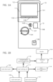
- FIG. 1A is a front view of the appearance of an example of the article supply device 10 corresponding to the embodiment.
- the main body of the article supply device 10 comprises a front wall, rear wall and side walls, an article accommodation unit 11 (which is also referred to as an article accommodation device or an article holding device) is a container (or a bucket or a case etc.) in which articles to be supplied to a user by the article supply device 10 are accommodated and the article accommodation device 11 is attached to the article supply device 10.
- an article accommodation unit 11 which is also referred to as an article accommodation device or an article holding device
- a container or a bucket or a case etc.
- the article accommodation unit 11 may be attached to the article supply device 10 by sliding it from a front side of the article supply device 10 toward the rear side thereof, along a prescribed rail arranged inside a cover portion 12. In addition, the article accommodation unit 11 can be removed from the article supply device 10 by pulling out the article accommodation unit 11from the article supply device 10 along the rail.
- the rear wall of the article accommodation unit 11 and a rear wall of the article supply device 10 may be configured so as not to be brought in contact with each other at the time of attachment thereof.
- the article accommodation unit 11 is made of plastic.
- a region 101, on which information relating to articles to be supplied can be presented, is provided, on a front face thereof.
- the accommodation unit 11 may be configured so that the articles accommodated thereinside can be viewed or cannot be viewed from the outside.
- the articles, such as sheets, printed matters, cards, CDROM case etc., can be are laminated and accommodated inside the article accommodation unit 11.
- a ⁇ supply port 102 of an article is provided in the article accommodation unit 11, and a shutter 103 is provided on the supply port (opening/closing door) so as to prevent injustice access to the inside of the article accommodation unit 11 from the supply port 102.
- the article accommodation unit 11 is provided on an upper side of the main body 13.
- a handle 104, a cash input port 105, a cash return port 106, a cash return button 107, and a notification portion 108 for issuing a notification that there is no article in the article accommodation unit 11, are provided on a front face of the main body 13.
- the handle 104 is an operation member which is configured so as to be rotatable in a direction shown in an arrow according to a payment of consideration.
- the shutter 103 is opened, and an article located at a lowest position, among articles accommodated in the article accommodation unit 11, is supplied from the supply port 102.
- the rotation of the handle 104 is limited in a state where a payment of the consideration cannot be confirmed.
- the lock mechanism is released so that the handle 104 becomes rotatable.
- the cash input port 105 is used for feeding coins when the consideration is paid in cash.
- Two or more kinds of input ports may be provided depending on the sizes of coins.
- input ports having sizes capable of respectively receiving five-hundred-yen coins and hundred-yen coins may be provided.
- FIG. 1A a common input port for five-hundred-yen coins and the hundred-yen coins is provided, and the input port corresponding to the size of the hundred-yen coins is sealed (closed).
- the cash input port 105 can be switched between a state where an input of cash is accepted and a state where it is not accepted, by controlling a mechanism thereinside.
- the article accommodation unit 11 may have a mechanism for detecting the presence of an article. When it does not detect the presence of any article, the input port may be closed so as not to receive any coins. When the inside of the article accommodation unit 11 cannot be visually recognized from the outside, it is possible to prevent coins from being inputted even though there is no article therein.
- a depression portion having a curved face is formed and an input port is formed near the bottom of the depression (the deepest part).
- the cash return port 106 is configured so as to return the fed coins according to an operation performed to the cash return button 107 so that the user can take out the returned coins from the device.
- FIG. 1B shows a block function diagram of a hardware mechanism (which may partially include software) in the article supply device 10.
- Coins inputted from the cash input port 105 are held in a cash holding unit 111, and the compensation payment detection portion 112 determines whether or not it reaches a predetermined amount.
- the compensation payment detection portion 112 determines that it reaches a predetermined amount
- a lock of the rotation unit 113 connected to the handle 104 is released so that the handle 104 becomes rotatable.
- the handle 104 can be rotated thereby.
- the rotation unit 113 is rotated, the coins held in the cash holding unit 111 are discharged into a coin accommodation unit 114, and the rotation unit 113 is locked again.
- the cash return button 107 is operated, the cash held in the cash holding unit 111 is returned from the cash return port 106.
- the notification portion 108 When there is no article in the article accommodation unit 11, the notification portion 108 notifies of it. In response to the result of detection performed by the detection portion for detecting whether or not there is an article in the article accommodation unit 11, when there is no article therein, the notification portion 108 issues, to the outside, a visually recognizable notification to the effect that there is no article.
- front front side
- rear rear
- left left side
- right right side
- upper upper side
- low low
- the article accommodation unit 11 includes the main body in an approximately rectangular parallelepiped shape, which comprises an exterior wall portion 200 forming a circumferential portion of the article accommodation unit 11, and the placing unit 201 on which an article is placed.
- An upper face of the placing unit 201 and a lower end face of the supply port 102 form the same plan as each other.
- the placing unit 201 divides an inner space of the article accommodation unit 11 into a first space located on an upper side of the placing unit 201 and a second space located on a lower side of the placing unit 201.
- Articles placed on the placing unit 201 inside the he first space may have various sizes.
- the shape of the articles is an approximately rectangular parallelepiped shape and the size thereof may be identified by width x length x height.
- the width, the length and the height respectively correspond to amplitudes of X axis, Y axis and Z axis of a coordinate system shown in FIG. 2A .
- the articles may be, for example, ones having a thickness such as CD ROM cases DVD cases in addition to name card size to A4 size sheets or cards.
- a first holding portion 202L and 202R and a second holding portion 203 are disposed in the first space, in order that various sizes of articles can be discharged.
- the first holding portion 202L and 202R support articles from a side thereof in the width direction of the articles, can be moved in the width direction (X axis) along the rails formed on the placing unit 201, so that a distance (W1) between the first holding portion 202L and 202R may be adjusted so as to be the size corresponding to the width of the article.
- the first holding portions 202L and 202R are movable on the rails along the width direction of the depressing portion 205, and the first holding portions 202L and 202R are configured to be movable in directions where they come close to each other or separate from each other.
- the second holding portion 203 supports the articles from a side thereof in a depth direction of the articles, and can be moved in the depth direction (Y axis) along rail(s) formed on the placing unit 201, so that a distance (L1) between the second holding portion 203 and a position where a tip portion of the articles on a side of the article supply port 102 is located may be set to the size corresponding to the length of the article.
- the moving range of the second holding portion 203 on the rail(s) is larger than that of the first holding portion 202 on the rails.
- the switch 204 is a detection portion for detecting whether or not there is any article(s) in the article accommodation unit 11.
- the detection is performed since the article presses it downward.
- the article(s) is depressed downward by the depressing portion 205 and is held, so that even if only single sheet article remains, the depressing force from the depressing portion 205 is transmitted to the switch 204 through the single article, whereby the presence of the article can be detected.
- the switch 204 since the switch 204 is not directly depressed by the depressing portion 205, the switch 204 is not depressed so that it is possible to detect that there is no article, when there is no article.
- the depressing portion 205 is movable in a downward direction due to its own weight and depresses, in the downward direction, a tip portion (a front portion) of the article(s) on an article supply port 102 side thereof held by the first holding portion 202 and the second holding portion 203.
- the depressing portion 205 is configured so as to be detachable from the main body through rails 208 described later.
- a guide portion 206 functions to guide an article accommodated in the article accommodation unit 11 when the article is sent out to the outside.
- the guide portion 206 adjusts the height from the placing unit 201 according to the height of a single article so as to discharge only the single article through the article discharge path from the supply port 102.
- FIG. 2B is in a cross-sectional view of an example of the structure of the article accommodation unit 11, taken along a line A-A' shown in FIG. 2A .
- the structural elements 201 to 206 are the same as those explained referring to FIG. 2A .
- the height of the first holding portion 202 and that of the second holding unit 203 approximately coincide with each other, and the laminated amount of the articles which can be accommodated in the article accommodation unit 11 is determined according to a volume specified by the first holding portion 202 and the second holding unit 203.
- a roller 207 for discharging the article and part of a transfer mechanism for transferring a turning force of the handle 104 to a roller 207 are arranged on a lower side of the placing unit 201 for placing an article in the second space of the article accommodation unit 11.
- the roller 207 is provided near the center in the width direction of the article accommodation unit 11 (or depressing portion 205), and is interlocked with the handle 104 so that the roller 207 is rotated when the handle 104 is rotated. Slip resistance such as rubber is formed on the surface of the roller 207.
- a cross section of the roller 207 has a circular cylindrical shape with a cut-out. By the cut-out, only one article can be discharged by one rotation of the handle. If the roller is formed in a perfect circular cylindrical shape, the articles are discharged in series. Therefore, such a cut-out is formed so that only one article is discharged.
- the shutter 103 is operated so as to be opened toward the outside of the article accommodation unit 11. By this, only when the roller 207 is rotated, the shutter 103 is opened so that the article is supplied.
- the shutter 103 is configured so that two or more opening/closing doors are arranged in the width direction of the article accommodation unit 11, and at least one of the opening/closing doors is opened when such an article is supplied.
- the shutter 103 may be configured by first through third opening/closing doors. Only the second opening/closing door may be opened according to the width of the article, or all the three opening/closing doors may be opened.
- the rail 208 is a rail member for restricting movements of the depressing portion 205 in upper and lower direction so that the depressing portion 205 accurately depress the article.
- An operation unit 209 transfers a turning force of the handle 104 to the roller 207, and at least part of the operation unit 209 is projected from a bottom portion of the article accommodation unit 11 toward a lower side so as to be connected to the mechanism for transmitting the turning force of the handle 104 provided on the main body 13, which is located on a lower side of the article accommodation unit 11.
- FIG. 3A is a diagram showing an example of the outer structure of the guide portion 206.
- a reinforce member 302 is attached to a main member 301 of the guide portion 206, and engages with a support member 305 shown in FIG. 3B , and the height of the guide member 206 from the placing unit 201 is determined.
- the guide portion 206 is arranged so as to be attachable to and detachable from the article accommodation unit 11 through the support member 305.
- a holding portion 301A for holding the guide portion 206 is provided approximately at an center of the main member 301, and an indication portion 301B for identifying the position of the guide portion 206 is provided at an end of the holding portion 301.
- the indication portion 301B functions so as to indicate the current position of the guide portion 206 with respect to a scale indicating the position of the guide portion 206 arranged in the article accommodation unit 11.
- a first engaging portion 304A for engaging with the support member 305 is arranged near one end of the guide portion 206, and a second engaging portion 304B is arranged near the other end of the guide portion 206.
- a bottom face of the guide portion 206 coincides with a bottom face of the main member 301, and when the guide portion 206 is arranged in the article accommodation unit 11, this bottom face becomes approximately parallel to the upper face of the placing unit 201.
- the guide portion 206 may be made of, for example, plastic.
- a reinforce member 302 may be made of metal (for example, metal or other metal).
- the holding portions 302A and 302B form part of the reinforce member 302, and are used for holding it when the height of the guide portion 206 is adjusted.
- the member 303A and 303B are used for respectively attaching the first engaging portion 304A and the second engaging portion 304B to the main member 301.
- the first engaging portion 304A and the second engaging portion 304B are arranged slidably in an arrow direction (a longitudinal direction of the guide portion 206 and a width direction of the article accommodation unit 11) in a space formed between the main member 301 and the members 303A and 303B.
- the first engaging portion 304A and the second engaging portion 304B respectively have projections in the sliding directions (left and right directions), and engage with two or more steps of recesses (engaged portion or depressed portions) formed on the support member 305 so that the guide portion 206 is supported at a predetermined height.
- FIG. 3B is a diagram showing an example of the structure of the support member 305.
- the support member 305 is configured to have a first support member 305A and a second support member 305B.
- the first support member 305A and the second support member 305B respectively have recesses formed at both left and right ends thereof on their front sides. The distances from the respective recesses to the bottom face of the support member 305 or to an upper face of the placing unit 201 at time when being accommodated in the article accommodation unit 11 are different from each other.
- the support member 305 has a first face which faces a region 101 of the article accommodation unit 11 or the supply port 102, and a second face on the other side.
- FIG. 3B mainly shows the structure on a side of the second face of the support member 305.
- FIG. 3A also shows the structure of the guide portion 206 on the side of the second face.
- the first support portion 305A has a first engaged portion and a second engaged portion comprising two or more steps of recesses
- the second support portion 305B has a third engaged portion and a fourth engaged portion.
- the first to fourth engaged portions respectively comprises recesses whose number is the same as one another (for example, four steps), and the heights of the respective recesses of the first engaged portion and those of the fourth engaged portion (from the bottom face 306 of the support member 305 or the upper face of the placing unit 201 when being arranged in the article accommodation unit 11), coincide with each other, and the heights of the respective recesses of the second engaged portion and those of the third engaged portion coincide with each other.
- the height position of the lowest step recess of the first engaged portion and that of the fourth engaged portion coincide with each other, and similarly the height position of the highest step recess of the second engaged portion and that of the third engaged portion coincide with each other.
- the height position of the lowest step recess of the second engaged portion and that of the third engaged portion coincide with each other, and similarly the height position of the highest step recess of the second engaged portion and that of the third engaged portion coincide with each other.
- FIG. 3B shows an example of arrangement of the first engaging portion 304A and the second engaging portion 304B.
- the first engaging portion 304A engages with the lowest step of the first engaged portion
- the second engaging portion 304B engages with the lowest step of the fourth engaged portion so that the position of the bottom face of the guide portion 206 is lowest, so as to be responsive to case where the single article is the thinnest. Since the number of steps which respectively form pairs is predetermined, when one of engaging portions engages with the first engaged portion (or fourth engaging portion) in a certain step, the other engaging portion engages with the fourth engaged portion (or first engaged portion) in a corresponding step.
- one of the engaging portion engages the second engaged portion (or the third engaged portion) in a certain step
- the other engaging portion engages with the third engaged portion (or the second engaged portion) in a corresponding step.
- the first engaging portion 304A and the second engaging portion 304B are slid in a width direction of the article accommodation unit 11 (a longitudinal direction of the guide portion 206, a width direction of an article) for engagement, that is, for example, the first engaging portion 304A is slid in a first longitudinal direction (leftward) so as to engage with the first engaged portion and the second engaging portion 304B is slid in a second longitudinal direction (rightward) which is a direction opposite to the first longitudinal direction so as to engage with the fourth engaged portion, or the first engaging portion 304A is slid in the second longitudinal direction (rightward) so as to engage with the second engaged portion and the second engaging portion 304B is slid in the first longitudinal direction (leftward) so as to engage with the third engaged portion, so that it is possible to cope with an arbitrary height of an article(s).
- the first engaging portion 304A can engage with an engaged portion, that is, either the first engaged portion or the second engaged portion, by sliding the first engaging portion 304A, and the second engaging portion 304A can engage with an engaged portion, that is, either the third engaged portion or the fourth engaged portion by sliding the first engaging portion 304A.
- FIG. 4A shows a state where the first engaging portion 304A and the first support portion 305A are engaged with each other.
- the article accommodation unit 11 is configured so that each engaging portion and each support portion are engaged with each other in a state where the guide portion 206 is brought into contact with the support member 305.
- the first engaging portion 304A engages with a lowest step recess of the first engaged portion.
- FIG. 4B is a diagram showing an enlarged view of the first engaging portion 304A and the first support portion 305A in a state where they are engaged with each other. As shown in FIG.
- the first engaging portion 304A has circular cylindrical shaped projections 401 and 402 on left and right sides thereof and a convex operation portion 403 is formed at the apex thereof.
- the shape of the first engaging portion 304A and that of the second engaging portion 304B are not limited to those shown in FIG. 4B as long as they have projections in a circular cylindrical shape in at least part thereof.
- a user can slide each engaging portion by operating the operation portion 403.
- Each of the engaged portions (recesses) 404 formed on the first support portion 305A is formed to so as to be C-shaped or inclined U-shaped, and is configured so as to be open on the second face side of the support member 305.
- FIG. 4C is a diagram showing a relation between the operation portion 301B provided in the holding portion 301A of the main member 301 and the scale portion 404.
- a scale corresponding to positions of the guide portion 206 which correspond to the respective steps of the first through fourth engaged portions is formed so that it is possible to specify the current step of the engaged portion from the position indicated by the indication portion 301B.
- numerical values indicating the steps may be associated therewith and formed.
- numerical values for indicating the height of the guide portion 206 or numerical values for indicating the height or size of an article are formed on the scale portion 404.
- FIG. 5 is a diagram showing the structure around the guide portion 206, which is viewed from a side of a right side face of the article accommodation unit 11.
- the position of the guide portion 206 is fixed by inserting a tip portion 501a of a fixing member 501 in a gap between an end portion of the main member 301 and a rail 208R.
- a slant is formed on the side of the fixing member 501 to which the tip portion 501a is attached, thereby preventing deviation of the tip portion of the main member 301.
- FIG. 5 shows only the structure on the right side face thereof, and the position of the left side end portion of the main member 301 may be fixed by a similar structure.
- a portion enclosed in a dot-line circle indicates a distance d from the upper face of the placing unit 201 of the guide 206 (the main member 301), wherein the distance d changes depending on the position of the engaged portion (recess) with which an engaging portion engages.
- the distance d changes depending on the position of the engaged portion (recess) with which an engaging portion engages.
- ⁇ an equal distance
- ⁇ the distance d
- the distance d di + ⁇ (n - 1), wherein di is an initial value corresponding to the first step (the lowest step) (n is a value corresponding to any one of the steps 1-8).
- the value of ⁇ may vary. For example, the higher a step, the smaller or the larger the increased amount.
- the position of the lower end portion of the shutter 103 coincides with the position of the upper face of the placing unit 201.
- FIG. 6A shows an example of an outer appearance of the depressing member 205.
- FIG. 6B shows an example of an out appearance of the rail 208.
- FIG. 6C is a sectional view of an example of the structure of the article accommodation unit 11 around the depressing portion 205.
- the depressing portion 205 is a member extending along a width direction of an article(s) placed in the article accommodation unit 11 (or a width direction of the article accommodation unit 11), and depresses a front portion of the article(s) located on a side of the supply port 102 from an upper side of the article(s) when the article(s) is placed in the article accommodation unit 11.
- the depressing portion 205 depresses the front portion from the upper face side which is directly above the arranged roller 207, thereby pushing the article(s) toward the roller 207 so that a turning force of the roller 207 can be accurately transmitted to the article.
- the depressing portion 205 is configured so as to be movable in up and down directions along the rails 208L and 208R which are arranged left and right ends of the depressing portion 205.
- the depressing portion 205 can be detached from the rails 208 by operating an upper projection portion 601.
- Engaging portions 602 are formed at both ends of the depressing portion 205, and when the engaging portions 206 engage with the cutouts 611 of the rails 208, the position of the depressing portion 205 is determined.
- the cutout 611 has an open end 611A on an upper side thereof, and an end portion 611B on a lower side thereof.
- the engaging portion 602 is inserted from the open end 661A so that the depressing portion 206 may naturally drop along the cutout portion 611 due to its own weight.
- the depressing portion 205 is located at the lowest point thereof when the engaging portion 602 reaches the end portion 611B.
- the depressing portion 205 has, on a lower portion thereof, a protection member 604 for protecting the switch 204.
- the protection member 604 functions to prevent an operation from the outside through the supply port 102 from being performed when the switch 204 is projected to an upper side thereof in case where there is no article in the article accommodation unit 11.
- the protection member 604 has a holding portion 605, and the switch 204 is positioned within the holding portion 605, thereby holding the switch 204. By this configuration, it is possible to prevent the switch 204 from being broken down by operating the switch from the outside.
- the projection portions 603 are brought into contact with the rails 208 and reduce a load applied to the engaging portion 602 in the front and rear directions of the article accommodation unit 11, thereby preventing brokage of the engaging portion 602.
- a convex portion 606 is formed on a bottom portion of the depressing portion 205 so as not to interfere a rotation of the roller 207.
- the shape of the concave portion 606 is not limited as long as it does not interfere with a rotation of the roller 606, for example, the shape pay be a circumferential depression along the rotation of the roller.
- the concave portion 606 is formed in only a portion where the roller 606 is arranged.
- the surface of the concave portion 606 forms a plane connected to the opening portion 201A provided in the placing unit 201.
- FIG. 7A shows a state where the first holding portions 202L and 202R and the second holding portion 203 are respectively arranged on the placing unit 201.
- the first holding portions 202L and 202R can be moved in a width direction of the article accommodation unit 11 along openings 701L and 701R formed on the placing unit 201 and rails 702L and 702R.
- the second holding portion 203 can be moved in a depth direction of the article accommodation unit 11 along an opening 703 and a rail 704 formed on the placing unit 201.
- the first holding portions 202L and 202R and the second holding portion 203 have a lock mechanism for stopping them at respectively predetermined positions, so stop positions corresponding to the sizes of the articles may be assigned thereto in advance.
- the openings 705 formed on the placing unit 201 are used to determine the position of the second holding portion 203.
- the second holding portion 203 may be fixed to and supported by the placing unit 201 by attaching lock members for the second holding portion 203 to the second holding portion 203 through the openings.
- the two or more openings 705 may be formed at positions corresponding to the lengths in the depth direction of articles along the long side of the opening 703. By this configuration, the second holding portion 203 can be fixed to the placing unit 201 through the respective openings 703 by using the lock members.
- the projection portion 203D is a member for releasing the lock state caused by the lock member.
- the lock member engaged with the opening 705 etc. is pushed down in a lower side thereof, so that the lock may be released.
- the lock member is biased in a direction of the second holding portion 203 by a spring etc. and when press of the projection 203D is released at a position where an opening is formed on the placing unit 201, the lock member engages with the opening by the biasing force so that a stop position of the second holding portion 203 can be fixed.
- Such a mechanism comprising the lock members and the projection portion 203D etc. can be adopted for the first holding member 202 in a similar manner.
- a projecting portion 203A is arranged at a tip of the second holding portion 203.
- the projecting portion 203A is configured so as to be movable in up and down directions along an opening 203B formed in the second holding portion 203.
- the opening 203B is formed from the upper end of the second holding portion 203 to the height as high as approximately the middle thereof so that the projecting portion 203A cannot move in lower side beyond that.
- elastic bodies 203C are attached to a back side of the second holding portion 203, and the elastic force of the elastic bodies is applied to the projecting portion 203A so that the projecting portion 203A is pushed down toward the lower side.
- the elastic force is applied to an upper face of the articles laminated on the placing unit 201 through the projecting portion 203A so that the upper face is pushed down toward a lower side.
- the elastic force may be applied in a range in which the second holding portion 203 moves within the opening 203B or in part of the range. At that time, when the height of the laminated articles is higher than a predetermined value, for example, when it is higher than a lower end portion of the opening 203B, it is pushed down below the projecting portion 302A.
- the elastic body may be, for example, rubber or spring as long as such an elastic force can be generated.
- the projecting portion 203A may be in an approximately hexagonal shape which can be formed by cutting out a top portion of a rectangular shape on a front side of the article accommodation unit 11. Or, the projecting portion may be elliptic, semicircular or a semielliptic or other shape. In addition, the projecting portion 203A has a shape where a length in a width direction is longer than that in the depth direction, and is configured so as to press at least part of a back side of articles laminated on the placing unit 201.
- FIG. 7B illustrates a movable range of the first holding portions 202 and the second holding portion 203 on the placing unit 201.
- the movable range of the first holding portions 202 is shown in an arrow D1
- the movable range of the second holding portion 203 is shown in an arrow D2, wherein a relation D2 > D1 is established.
- FIG. 8A shows a state of the article accommodation unit 11 in case where an article is present in the article accommodation unit 11.
- the switch 204 is biased toward an upper side, but pressed toward a lower direction by the article 800, the notification display unit 801 is not visible from the outside in the notification portion 108.
- the tip portion 204A of the switch 204 is located in the same plane as that of the placing unit 201.
- the notification display unit 801 is connected to an L-shaped member 802 which is in contact with a projection portion 204B of the switch 204 through a rotational axis, and the L-shaped member 802 is biased by a spring etc. so as to rotate in a clockwise direction in FIG. 8A .
- the rotation of the L-shaped member and the notification display unit 801 which is interlocked with the L-shaped member 802 is suppressed by the projection portion 204B of the switch 204.
- the tip portion 204A of the switch 204 projects into an upper side of the placing unit 201 according to the upward biasing force so that the projection portion 204B, which restrains the rotation of the L-shaped member 802, also moves toward the upper side.
- the L-shaped member 802 is rotated in a direction shown in an arrow, and accordingly the notification display unit 801 is also rotated downwardly.
- a message region 801A of the notification display unit 801 shown in FIG. 8C becomes visible from the outside through the notification portion 108.
- the notification portion 108 comprises a member made of a transparent plastic or glass etc. so that a user can visibly recognize the message region 801A from the outside through the member.
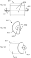
- FIG. 9 shows an example of a configuration of the roller 207.
- FIG. 9A is a front side view of the roller 207.
- a rotation axis 901 is projected leftward and rightward from the respective sides of the roller 207.
- the roller 207 rotates with respect to the rotation axis 901.
- the rotation axis is interlocked with the handle 104 through a certain mechanism, so that when the handle 104 is rotated by one revolution, the roller 207 is also rotated by one revolution with respect to the rotation axis 901.
- a flat face portions 902 are formed on a surface of the roller 207 along the rotation axis 901 wherein the flat face portions 902 will not be brought in contact with an article to be sent out when the roller 207 is rotated.
- FIG. 9B is a side view of the roller 207, wherein a curved face portion 903 is formed on a back side of the flat face portions 902 of the roller 207.
- the roller 207 has a shape like a partially cut-out portion which is formed by removing an outer face of a cylinder. The removed portion corresponds to the flat face portion 209, and the remaining semi-cylinder portion corresponds to the curved face portion 903.
- the remaining portion is larger than the cur-out portion.
- the area of the curved face portion 903 is larger than that of the flat face portions 902.
- FIG. 9C shows a back face of the roller 207, wherein the curved face portion 903 of the roller 207 is brough in contact with an article and functions to transmit the article to the supply port 102. It is desired that the curved face portion 903 is covered with grippy material on its surface, such as soft material like rubber etc. or slip resistance material in order to transmit a turning force to the article when the curved face portion 903 is brought in contact with the article. However, the entire curved face portion is not necessarily covered with such soft material and at least part thereof should be covered therewith.
- the curved face portion 903 in a circumferential direction may be entirely covered with such material
- the curved face portion 903 in a width direction may be discontinuously covered therewith.
- the curved face portion 903 in the circumferential direction may be not necessarily continuously covered therewith but may be entirely covered with two or more soft material members.
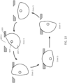
- FIG. 10 illustrates a relation between the opening portion and the roller 207.
- FIG. 10 is a state transition diagram showing the relation between rotation position of the roller 207 and placing unit 201.
- a state 1 shows an initial position of the roller 207 when the roller 207 starts a rotation.
- the roller 207 does not project from the opening portion 201A of the placing unit 201.
- the roller 207 rotates counterclockwise with respect to the rotation axis 901 in FIG. 10 , and at least part of the roller 207 projects from the opening portion 201A, and the roller 207 is brought into contact with the article placed on the placing unit 201, from an end of on the right side thereof, so that the article is pushed out toward a front side of the article accommodation unit 11.
- the state 2 where the curved face portion 903 of the roller 207 projects from the opening portion 201A shifts to the state 4 through the states 2 and 3.
- the curved face portion 903, which projects from the opening portion 201A is brought into contact with the article, so that a force for pushing an article toward the front side is exerted.
- the roller207 is in "a transmittable state.” After an end of the left side of the roller 207 is brought into contact therewith in the state 4, the roller 207 is not in contact with the article as shown in the state 5.
- the roller 207 is in a transmission incapable state". In this state, although the position of the article does not move, the article is exposed to the outside enough to the extent that the article can be taken out from the supply port 102. The user can take out the article from the article accommodation unit by pulling out a portion thereof which is exposed from the supply port 102.
- FIG. 11 is a schematic view for illustrating the power transmission system.
- an end of a main shaft body 1101 which forms part of gear interlocking mechanism is attached to a rotational central axis of the handle 104.
- a spur gear 1102 is fixed to the other end of this main shaft body 1101.
- a pinion 1103 which meshes with the spur gear 1102 is rotatably journalled above the spur gear 1102.
- a spur gear 1104 which meshes with the pinion 1103 is journalled at a lower end of a back face of the article accommodation unit 11.
- a turning force is transmitted to the spur gear 1102 through the main shaft body 1101 when the handle 104 is manually rotated by one revolution in a direction of an arrow T1, and the turning force is transmitted to the spur gear 1104 through the pinion 1103 which meshes therewith in a direction f an arrow T2. And when the operation to the handle 14 is continued, the spur gear 1104 is rotated by one revolution.
- a spur gear 1106 which meshes with the spur gear 1102 is rotatably journaled.
- an intermediate shaft 1108 is rotatably journaled, wherein a pinion 1107 meshing with the spur gear 1106 is attached to one end of the intermediate shaft 1108.
- a bevel gear 1019 is attached to an end of the intermediate axis 1108.
- the intermediate shaft 1008 is rotated via the spur gear 1106 and the pinion 1107 by the rotation of the spur gear 1102 thereby rotating the bevel gear 1109. Therefore, if the rotation of the bevel gear 1109 is restricted, the rotation of the handle 104 and that of the spur gear 1104 is also restricted.
- a bevel gear 1110 meshes with the bevel gear 1109. Therefore, when the bevel gear 1109 is rotated by rotation of the handle 104, the bevel gear 1110 is also rotated.
- the bevel gear 1110 is integrated with the rotation portion 113.
- the rotation portion 113 is a mechanism for releasing the lock of the handle 104 in response to a detection of insertion of a coin(s) equivalent to a predetermined amount of money by the compensation payment detection portion 112, and when the predetermined amount of money has not been inserted, the rotation portion 113 is locked. In this case, the bevel gear 1110 and the bevel gear 1109 cannot be rotated, so that the rotation of the handle 104 is prevented.
- the main shaft body 1101 to which the handle 104 is directly connected, and the intermediate axis 1108 to which the bevel gear 1109 interlocked with the rotation portion is attached, are separately provided.
- the bevel gear 1109 may be provided to the main shaft 1101.
- FIG. 12A is a diagram showing a configuration of an example of a transmission system.
- the transmission system when the lock of the switch 1201 is released and the spur gear 1104 provided on a back wall of the article accommodation unit 11 is rotated, a turning force is transmitted to the roller 207 through the spur gear 1202, the main shaft body 1203, the bevel gears 1204 and 1205 and the intermediate axis 1206.
- the switch 1201 functions as a lock portion for performing control as to whether the spur gear 1104 shown in FIG. 11 can be rotated.
- the projection 1201 is pressed so that the engagement state (contact state) of the projection of the tip portion of the switch 1201 (1201D in FIG. 12C ) and the spur gear 1104 is released, so that the spur gear 1104 becomes rotatable. Further, as shown in FIG.
- a concave portion 1104B which engages with the projection 1201D provided at the tip portion of the switch 1201 is formed on a side face portion of the spur gear 1104, where no tooth is not formed.
- the switch 1201 is configured so as to be swingable with respect to an axis 1201A. And, the switch 1204 is biased in a first direction shown in an arrow by the bias portion 1201B, and the projection 1201D of the tip portion of the switch 1201 is activated through the axis 1201A by the bias force in a direction in which the spur gear 1104 is locked.
- the projection 1021D engages with the spur gear 1104 by the bias force generated by the bias portion 1201B, so that a rotation operation of the spur gear 1104 is restrained. Further, a projecting direction of the projection 1201C of the switch 1201 is also the first direction. The projection 1201D of the switch 1201 projects in a second direction opposite to the first direction.
- the spur gear 1104 engages with the spur gear 1202 and a power from the handle 104 is transmitted to the main shaft body 1203.
- a middle part in the length of the main shaft body 1203 is omitted.
- the rotation of the main shaft body 1203 is transmitted to the roller 20 through the bevel gear 1204 and 1205 and the intermediate axis 1206.
- the rotation of the handle 104 can be transmitted to the roller 207.
- the spur gears 1104 and 1202 are covered by a cover 1207, since the spur gear 1104 engages with the pinion 1103, part of the spur gear 1104 is exposed to the outside of the cover 1207.
- the cover 1207 protects the spur gears 1104 and 1202 so as not to interfere with the rotation by bringing the spur gears 1104 and 1202 into contact with an inner side of the back wall of the article supply device 10.
- FIG. 12B is a diagram showing a state where the spur gear 1104 and the spur gear 1202 engage with each other, wherein a mark 1104A shown on the spur gear 1104 and a mark 1202A shown on the spur gear 1202 face each other at corresponding positions.
- the roller 207 since the roller 207 has the shape in which part of a cylinder is cut out, it is necessary to correctly determine the rotation start position of the roller 207 so that the article and the curved face portion 903 are correctly brought into contact with each other when the roller 207 is rotated. If the curved face portion 903 and the article are not correctly brought into contact with each other, there is possibility that the article is not discharged from the article supply port 102.
- the rotation position of the spur gear 1104 can be changed by manually and arbitrarily rotating the spur gear 1104. Therefore, when the article accommodation unit 11 is re-attached to the article supply device 10 after the article accommodation unit 11 is detached from the article supply device 10, it is possible to certainly discharge the article from the article supply device 10 without any false operation by manually rotating the spur gear 1104 by adjusting the rotation positions of the spur gears 1104 and 1202 so that the mark 1104A and the mark 1202A face each other.
- the switch 1201 When the spur gear 1104 is located at the position shown in FIG. 12B (a first position), the switch 1201 is arranged so as to engage with the concave portion 1104B of the spur gear 1104.
- the concave portion 1104B has a concave depth enough to engage with the projection 1201D of the switch 1201.
- a lock operation can be done by the switch 1201.
- a position other than the first position a second position
Landscapes
- Physics & Mathematics (AREA)
- General Physics & Mathematics (AREA)
- Business, Economics & Management (AREA)
- Accounting & Taxation (AREA)
- Finance (AREA)
- Strategic Management (AREA)
- General Business, Economics & Management (AREA)
- Engineering & Computer Science (AREA)
- Theoretical Computer Science (AREA)
- Vending Machines For Individual Products (AREA)
Abstract
Description
- The present invention relates to an article accommodation device and an article supply device.
- There is a device for supplying an article according to payment of compensation.
Patent Document 1 discloses an article supply device capable of supplying an article according to payment of compensation. - [Patent Document 1 ]
Japanese Patent Application Publication No. 2008-27226 - However, in
Patent Document 1, an article(s) to be supplied is not sheet-shaped or case-shaped. On the other hand, there is a demand for a configuration in which a sheet shaped or case shaped article is made suppliable by accommodating such articles and attaching it to an article supply device. - Therefore, provided herein is an article accommodation unit which has a configuration capable of supplying a sheet-shaped or case shaped article etc. and which can be attached to an article supply device, and the article supply device to which the article accommodation unit is attached.
- One of the aspects of the present invention is an article accommodation device which can be attached to an article supply device, comprises a main body; a transportation unit which is provided in the main body, and which transports an article accommodated in the main body to an outside of the article accommodation unit, wherein the transportation unit is configured to take either a transportation capable state where the article can be transported or a transportation incapable state where the article cannot be transported.
- Still another aspect of the present invention is an article supply device, which comprises the article accommodation unit and a reception unit which receives payment of compensation for the article, a detection portion which detects the payment of compensation, an operation unit which accepts an operation for transporting the article accommodated in the article accommodation unit in response to a detection of the payment of compensation, and a power transmission unit for transmitting a power of the operation to the transportation unit, and transporting the article.
- It is possible to provide an article accommodation unit which is configured to supply a sheet or a case etc. as an article, and which can be attached to an article supply device, and an article supply device to which the article accommodation unit is attached.
-
-
FIG. 1 shows an example of a configuration of anarticle supply device 10 and a hardware configuration of thearticle supply device 10 according to an embodiment; -
FIG. 2 shows an example of a configuration of anarticle accommodation unit 11 according to an embodiment; -
FIG. 3 illustrates a configuration of aguide portion 206 and asupport member 305 according to an embodiment; -
FIG. 4 illustrates a configuration of aguide portion 206 and asupport member 305 according to an embodiment; -
FIG. 5 is a diagram of a structure around theguide portion 206 according to an embodiment, which is viewed from a right face side of thearticle accommodation unit 11; -
FIG. 6 illustrates a configuration of adepression portion 205 and arail 208 according to an embodiment; -
FIG. 7 illustrates a configuration of a first holding portion 202 and asecond holding portion 203 according to an embodiment; -
FIG. 8 illustrates an interlocking structure between a notice of the presence of an article in aswitch 204 and a notification in anotification portion 108, according to an embodiment; -
FIGS. 9A, 9B and 9C illustrate a configuration of aroller 207 according to an embodiment; -
FIG. 10 is a diagram illustrating a relation between anopening portion 201A of a placingunit 201 and aroller 207 according to an embodiment; -
FIG. 11 is a diagram illustrating a power transmission mechanism on a side of amain body 11 for transmitting a power corresponding to an operation to ahandle 104 according to an embodiment; and -
FIG 12 illustrates a power transmission mechanism on a side of anarticle accommodation unit 11 for transmitting a power corresponding to an operation to thehandle 104 according to an embodiment. - An embodiment will be explained below in detail, referring to attached drawings. It should be noted that the embodiments set forth below do not limit the claimed invention and all the combinations of features explained in the embodiments may not be necessarily essential to the present invention. Two or more features among a plurality of the features explained in the embodiments may be arbitrarily combined with each other. The same reference numbers are assigned to similar structures or the same structures and duplicate explanation thereof will be omitted
- A configuration of an
article supply device 10 will be described referring toFIG. 1A. FIG. 1A is a front view of the appearance of an example of thearticle supply device 10 corresponding to the embodiment. InFIG. 1A , the main body of thearticle supply device 10 comprises a front wall, rear wall and side walls, an article accommodation unit 11 (which is also referred to as an article accommodation device or an article holding device) is a container (or a bucket or a case etc.) in which articles to be supplied to a user by thearticle supply device 10 are accommodated and thearticle accommodation device 11 is attached to thearticle supply device 10. Thearticle accommodation unit 11 may be attached to thearticle supply device 10 by sliding it from a front side of thearticle supply device 10 toward the rear side thereof, along a prescribed rail arranged inside acover portion 12. In addition, thearticle accommodation unit 11 can be removed from thearticle supply device 10 by pulling out the article accommodation unit 11from thearticle supply device 10 along the rail. The rear wall of thearticle accommodation unit 11 and a rear wall of thearticle supply device 10 may be configured so as not to be brought in contact with each other at the time of attachment thereof. - The
article accommodation unit 11 is made of plastic. Aregion 101, on which information relating to articles to be supplied can be presented, is provided, on a front face thereof. Theaccommodation unit 11 may be configured so that the articles accommodated thereinside can be viewed or cannot be viewed from the outside. The articles, such as sheets, printed matters, cards, CDROM case etc., can be are laminated and accommodated inside thearticle accommodation unit 11. A\supply port 102 of an article is provided in thearticle accommodation unit 11, and ashutter 103 is provided on the supply port (opening/closing door) so as to prevent injustice access to the inside of thearticle accommodation unit 11 from thesupply port 102. - The
article accommodation unit 11 is provided on an upper side of themain body 13. Ahandle 104, acash input port 105, acash return port 106, acash return button 107, and anotification portion 108 for issuing a notification that there is no article in thearticle accommodation unit 11, are provided on a front face of themain body 13. - The
handle 104 is an operation member which is configured so as to be rotatable in a direction shown in an arrow according to a payment of consideration. When a user rotates thehandle 104, theshutter 103 is opened, and an article located at a lowest position, among articles accommodated in thearticle accommodation unit 11, is supplied from thesupply port 102. The rotation of thehandle 104 is limited in a state where a payment of the consideration cannot be confirmed. When the payment of the consideration is confirmed, the lock mechanism is released so that thehandle 104 becomes rotatable. - The
cash input port 105 is used for feeding coins when the consideration is paid in cash. Two or more kinds of input ports may be provided depending on the sizes of coins. For example, input ports having sizes capable of respectively receiving five-hundred-yen coins and hundred-yen coins may be provided. InFIG. 1A , a common input port for five-hundred-yen coins and the hundred-yen coins is provided, and the input port corresponding to the size of the hundred-yen coins is sealed (closed). - The
cash input port 105 can be switched between a state where an input of cash is accepted and a state where it is not accepted, by controlling a mechanism thereinside. Specifically, thearticle accommodation unit 11 may have a mechanism for detecting the presence of an article. When it does not detect the presence of any article, the input port may be closed so as not to receive any coins. When the inside of thearticle accommodation unit 11 cannot be visually recognized from the outside, it is possible to prevent coins from being inputted even though there is no article therein. - In the
cash input portion 105, a depression portion having a curved face is formed and an input port is formed near the bottom of the depression (the deepest part). By this configuration, even a small child may easily feed coins in thecash input port 105 by sliding the coin and tracing the curved face. Thecash return port 106 is configured so as to return the fed coins according to an operation performed to thecash return button 107 so that the user can take out the returned coins from the device. -
FIG. 1B shows a block function diagram of a hardware mechanism (which may partially include software) in thearticle supply device 10. Coins inputted from thecash input port 105 are held in acash holding unit 111, and the compensationpayment detection portion 112 determines whether or not it reaches a predetermined amount. When the compensationpayment detection portion 112 determines that it reaches a predetermined amount, a lock of therotation unit 113 connected to thehandle 104 is released so that thehandle 104 becomes rotatable. Thus, thehandle 104 can be rotated thereby. When therotation unit 113 is rotated, the coins held in thecash holding unit 111 are discharged into acoin accommodation unit 114, and therotation unit 113 is locked again. In addition, when thecash return button 107 is operated, the cash held in thecash holding unit 111 is returned from thecash return port 106. - When there is no article in the
article accommodation unit 11, thenotification portion 108 notifies of it. In response to the result of detection performed by the detection portion for detecting whether or not there is an article in thearticle accommodation unit 11, when there is no article therein, thenotification portion 108 issues, to the outside, a visually recognizable notification to the effect that there is no article. - Although in explanation of positional relations of the respective parts in the present specification, terms, front (front side), rear (rear side), left (left side), right (right side), upper (upper side), low (lower side) etc. are used, these terms indicate relative positions, when the
article supply device 10 is regarded as the standard. For example, front corresponds to a front face side of thearticle supply device 10, and rear corresponds to a back face side of thearticle supply device 10. In addition, right left up and down indicate right left up and down with respect to thearticle supply device 10 shown inFIG. 1 . - Next, a configuration of the
article accommodation unit 11 according to the present embodiment will be described referring toFIG. 2 . Thearticle accommodation unit 11 includes the main body in an approximately rectangular parallelepiped shape, which comprises anexterior wall portion 200 forming a circumferential portion of thearticle accommodation unit 11, and theplacing unit 201 on which an article is placed. An upper face of theplacing unit 201 and a lower end face of thesupply port 102 form the same plan as each other. In addition, theplacing unit 201 divides an inner space of thearticle accommodation unit 11 into a first space located on an upper side of theplacing unit 201 and a second space located on a lower side of theplacing unit 201. Articles placed on theplacing unit 201 inside the he first space may have various sizes. The shape of the articles is an approximately rectangular parallelepiped shape and the size thereof may be identified by width x length x height. The width, the length and the height respectively correspond to amplitudes of X axis, Y axis and Z axis of a coordinate system shown inFIG. 2A . The articles may be, for example, ones having a thickness such as CD ROM cases DVD cases in addition to name card size to A4 size sheets or cards. - A
first holding portion second holding portion 203 are disposed in the first space, in order that various sizes of articles can be discharged. Thefirst holding portion placing unit 201, so that a distance (W1) between thefirst holding portion first holding portions depressing portion 205, and the first holdingportions second holding portion 203 supports the articles from a side thereof in a depth direction of the articles, and can be moved in the depth direction (Y axis) along rail(s) formed on theplacing unit 201, so that a distance (L1) between thesecond holding portion 203 and a position where a tip portion of the articles on a side of thearticle supply port 102 is located may be set to the size corresponding to the length of the article. Here, the moving range of thesecond holding portion 203 on the rail(s) is larger than that of the first holding portion 202 on the rails. - Next, the
switch 204 is a detection portion for detecting whether or not there is any article(s) in thearticle accommodation unit 11. When there is an article(s) therein, the detection is performed since the article presses it downward. Here, the article(s) is depressed downward by thedepressing portion 205 and is held, so that even if only single sheet article remains, the depressing force from thedepressing portion 205 is transmitted to theswitch 204 through the single article, whereby the presence of the article can be detected. On the other hand, since theswitch 204 is not directly depressed by thedepressing portion 205, theswitch 204 is not depressed so that it is possible to detect that there is no article, when there is no article. - The
depressing portion 205 is movable in a downward direction due to its own weight and depresses, in the downward direction, a tip portion (a front portion) of the article(s) on anarticle supply port 102 side thereof held by the first holding portion 202 and thesecond holding portion 203. Thedepressing portion 205 is configured so as to be detachable from the main body throughrails 208 described later. Aguide portion 206 functions to guide an article accommodated in thearticle accommodation unit 11 when the article is sent out to the outside. Theguide portion 206 adjusts the height from the placingunit 201 according to the height of a single article so as to discharge only the single article through the article discharge path from thesupply port 102. -
FIG. 2B is in a cross-sectional view of an example of the structure of thearticle accommodation unit 11, taken along a line A-A' shown inFIG. 2A . Thestructural elements 201 to 206 are the same as those explained referring toFIG. 2A . InFIG. 2B , the height of the first holding portion 202 and that of thesecond holding unit 203 approximately coincide with each other, and the laminated amount of the articles which can be accommodated in thearticle accommodation unit 11 is determined according to a volume specified by the first holding portion 202 and thesecond holding unit 203. Aroller 207 for discharging the article and part of a transfer mechanism for transferring a turning force of thehandle 104 to aroller 207 are arranged on a lower side of theplacing unit 201 for placing an article in the second space of thearticle accommodation unit 11. - The
roller 207 is provided near the center in the width direction of the article accommodation unit 11 (or depressing portion 205), and is interlocked with thehandle 104 so that theroller 207 is rotated when thehandle 104 is rotated. Slip resistance such as rubber is formed on the surface of theroller 207. A cross section of theroller 207 has a circular cylindrical shape with a cut-out. By the cut-out, only one article can be discharged by one rotation of the handle. If the roller is formed in a perfect circular cylindrical shape, the articles are discharged in series. Therefore, such a cut-out is formed so that only one article is discharged. In addition, according to the rotation of theroller 207, theshutter 103 is operated so as to be opened toward the outside of thearticle accommodation unit 11. By this, only when theroller 207 is rotated, theshutter 103 is opened so that the article is supplied. - In addition, the
shutter 103 is configured so that two or more opening/closing doors are arranged in the width direction of thearticle accommodation unit 11, and at least one of the opening/closing doors is opened when such an article is supplied. According to the present embodiment, theshutter 103 may be configured by first through third opening/closing doors. Only the second opening/closing door may be opened according to the width of the article, or all the three opening/closing doors may be opened. Therail 208 is a rail member for restricting movements of thedepressing portion 205 in upper and lower direction so that thedepressing portion 205 accurately depress the article. - An
operation unit 209 transfers a turning force of thehandle 104 to theroller 207, and at least part of theoperation unit 209 is projected from a bottom portion of thearticle accommodation unit 11 toward a lower side so as to be connected to the mechanism for transmitting the turning force of thehandle 104 provided on themain body 13, which is located on a lower side of thearticle accommodation unit 11. - Next, the structure of the
guide portion 206 will be explained referring toFIG. 3. FIG. 3A is a diagram showing an example of the outer structure of theguide portion 206. A reinforce member 302 is attached to amain member 301 of theguide portion 206, and engages with asupport member 305 shown inFIG. 3B , and the height of theguide member 206 from the placingunit 201 is determined. Theguide portion 206 is arranged so as to be attachable to and detachable from thearticle accommodation unit 11 through thesupport member 305. A holdingportion 301A for holding theguide portion 206 is provided approximately at an center of themain member 301, and anindication portion 301B for identifying the position of theguide portion 206 is provided at an end of the holdingportion 301. Theindication portion 301B functions so as to indicate the current position of theguide portion 206 with respect to a scale indicating the position of theguide portion 206 arranged in thearticle accommodation unit 11. A first engagingportion 304A for engaging with thesupport member 305 is arranged near one end of theguide portion 206, and a secondengaging portion 304B is arranged near the other end of theguide portion 206. - A bottom face of the
guide portion 206 coincides with a bottom face of themain member 301, and when theguide portion 206 is arranged in thearticle accommodation unit 11, this bottom face becomes approximately parallel to the upper face of theplacing unit 201. Theguide portion 206 may be made of, for example, plastic. In such case, a reinforce member 302 may be made of metal (for example, metal or other metal). The holdingportions guide portion 206 is adjusted. - The
member portion 304A and the secondengaging portion 304B to themain member 301. The firstengaging portion 304A and the secondengaging portion 304B are arranged slidably in an arrow direction (a longitudinal direction of theguide portion 206 and a width direction of the article accommodation unit 11) in a space formed between themain member 301 and themembers engaging portion 304A and the secondengaging portion 304B respectively have projections in the sliding directions (left and right directions), and engage with two or more steps of recesses (engaged portion or depressed portions) formed on thesupport member 305 so that theguide portion 206 is supported at a predetermined height. -
FIG. 3B is a diagram showing an example of the structure of thesupport member 305. Thesupport member 305 is configured to have afirst support member 305A and asecond support member 305B. Thefirst support member 305A and thesecond support member 305B respectively have recesses formed at both left and right ends thereof on their front sides. The distances from the respective recesses to the bottom face of thesupport member 305 or to an upper face of theplacing unit 201 at time when being accommodated in thearticle accommodation unit 11 are different from each other. When being accommodated in thearticle accommodation unit 11, thesupport member 305 has a first face which faces aregion 101 of thearticle accommodation unit 11 or thesupply port 102, and a second face on the other side. The recesses offirst support portion 305A and those of thesecond support portion 305B are formed on the second face. That is,FIG. 3B mainly shows the structure on a side of the second face of thesupport member 305. Similarly,FIG. 3A also shows the structure of theguide portion 206 on the side of the second face. - The
first support portion 305A has a first engaged portion and a second engaged portion comprising two or more steps of recesses, and thesecond support portion 305B has a third engaged portion and a fourth engaged portion. The first to fourth engaged portions respectively comprises recesses whose number is the same as one another (for example, four steps), and the heights of the respective recesses of the first engaged portion and those of the fourth engaged portion (from the bottom face 306 of thesupport member 305 or the upper face of theplacing unit 201 when being arranged in the article accommodation unit 11), coincide with each other, and the heights of the respective recesses of the second engaged portion and those of the third engaged portion coincide with each other. That is, the height position of the lowest step recess of the first engaged portion and that of the fourth engaged portion coincide with each other, and similarly the height position of the highest step recess of the second engaged portion and that of the third engaged portion coincide with each other. In addition, the height position of the lowest step recess of the second engaged portion and that of the third engaged portion coincide with each other, and similarly the height position of the highest step recess of the second engaged portion and that of the third engaged portion coincide with each other. -
FIG. 3B shows an example of arrangement of the first engagingportion 304A and the secondengaging portion 304B. Here, the first engagingportion 304A engages with the lowest step of the first engaged portion and the secondengaging portion 304B engages with the lowest step of the fourth engaged portion so that the position of the bottom face of theguide portion 206 is lowest, so as to be responsive to case where the single article is the thinnest. Since the number of steps which respectively form pairs is predetermined, when one of engaging portions engages with the first engaged portion (or fourth engaging portion) in a certain step, the other engaging portion engages with the fourth engaged portion (or first engaged portion) in a corresponding step. Similarly, one of the engaging portion engages the second engaged portion (or the third engaged portion) in a certain step, the other engaging portion engages with the third engaged portion (or the second engaged portion) in a corresponding step. Compared with the case where only the first engaged portion and the fourth engaged portions are provided (or only the second engaged portion and the third engaged portion are provided), it is possible to more precisely set the height thereof when the second engaged portion and the third engaged portions (or the first engaged portion and the fourth engaged portions) are additionally provided. - In this way, the first engaging
portion 304A and the secondengaging portion 304B are slid in a width direction of the article accommodation unit 11 (a longitudinal direction of theguide portion 206, a width direction of an article) for engagement, that is, for example, the first engagingportion 304A is slid in a first longitudinal direction (leftward) so as to engage with the first engaged portion and the secondengaging portion 304B is slid in a second longitudinal direction (rightward) which is a direction opposite to the first longitudinal direction so as to engage with the fourth engaged portion, or the first engagingportion 304A is slid in the second longitudinal direction (rightward) so as to engage with the second engaged portion and the secondengaging portion 304B is slid in the first longitudinal direction (leftward) so as to engage with the third engaged portion, so that it is possible to cope with an arbitrary height of an article(s). The firstengaging portion 304A can engage with an engaged portion, that is, either the first engaged portion or the second engaged portion, by sliding the first engagingportion 304A, and the secondengaging portion 304A can engage with an engaged portion, that is, either the third engaged portion or the fourth engaged portion by sliding the first engagingportion 304A. -
FIG. 4A shows a state where the first engagingportion 304A and thefirst support portion 305A are engaged with each other. Thearticle accommodation unit 11 is configured so that each engaging portion and each support portion are engaged with each other in a state where theguide portion 206 is brought into contact with thesupport member 305. As shown inFIG. 4A , the first engagingportion 304A engages with a lowest step recess of the first engaged portion.FIG. 4B is a diagram showing an enlarged view of the first engagingportion 304A and thefirst support portion 305A in a state where they are engaged with each other. As shown inFIG. 4B , the first engagingportion 304A has circular cylindrical shapedprojections convex operation portion 403 is formed at the apex thereof. The shape of the first engagingportion 304A and that of the secondengaging portion 304B are not limited to those shown inFIG. 4B as long as they have projections in a circular cylindrical shape in at least part thereof. A user can slide each engaging portion by operating theoperation portion 403. Each of the engaged portions (recesses) 404 formed on thefirst support portion 305A is formed to so as to be C-shaped or inclined U-shaped, and is configured so as to be open on the second face side of thesupport member 305. -
FIG. 4C is a diagram showing a relation between theoperation portion 301B provided in the holdingportion 301A of themain member 301 and thescale portion 404. A scale corresponding to positions of theguide portion 206 which correspond to the respective steps of the first through fourth engaged portions is formed so that it is possible to specify the current step of the engaged portion from the position indicated by theindication portion 301B. In addition to the lines indicating the positions, numerical values indicating the steps may be associated therewith and formed. Or, numerical values for indicating the height of theguide portion 206 or numerical values for indicating the height or size of an article are formed on thescale portion 404. - Next,
FIG. 5 is a diagram showing the structure around theguide portion 206, which is viewed from a side of a right side face of thearticle accommodation unit 11. The position of theguide portion 206 is fixed by inserting atip portion 501a of a fixingmember 501 in a gap between an end portion of themain member 301 and arail 208R. When the height of theguide portion 206 from the upper face of theplacing unit 201 is adjusted, it is necessary to do it after the fixingmember 501 is detached. A slant is formed on the side of the fixingmember 501 to which thetip portion 501a is attached, thereby preventing deviation of the tip portion of themain member 301.FIG. 5 shows only the structure on the right side face thereof, and the position of the left side end portion of themain member 301 may be fixed by a similar structure. - In
FIG. 5 , a portion enclosed in a dot-line circle indicates a distance d from the upper face of theplacing unit 201 of the guide 206 (the main member 301), wherein the distance d changes depending on the position of the engaged portion (recess) with which an engaging portion engages. For example, when an equal distance (α) increases every time a recess goes up by one step, the distance d is expressed by d = di + α(n - 1), wherein di is an initial value corresponding to the first step (the lowest step) (n is a value corresponding to any one of the steps 1-8). In addition, the value of α may vary. For example, the higher a step, the smaller or the larger the increased amount. The position of the lower end portion of theshutter 103 coincides with the position of the upper face of theplacing unit 201. - Next, the structure of the
depressing portion 205 and therail 208 will be explained, referring toFIG. 6. FIG. 6A shows an example of an outer appearance of thedepressing member 205.FIG. 6B shows an example of an out appearance of therail 208.FIG. 6C is a sectional view of an example of the structure of thearticle accommodation unit 11 around thedepressing portion 205. - The
depressing portion 205 is a member extending along a width direction of an article(s) placed in the article accommodation unit 11 (or a width direction of the article accommodation unit 11), and depresses a front portion of the article(s) located on a side of thesupply port 102 from an upper side of the article(s) when the article(s) is placed in thearticle accommodation unit 11. Thedepressing portion 205 depresses the front portion from the upper face side which is directly above the arrangedroller 207, thereby pushing the article(s) toward theroller 207 so that a turning force of theroller 207 can be accurately transmitted to the article. Thedepressing portion 205 is configured so as to be movable in up and down directions along therails depressing portion 205. Thedepressing portion 205 can be detached from therails 208 by operating anupper projection portion 601. Engagingportions 602 are formed at both ends of thedepressing portion 205, and when the engagingportions 206 engage with thecutouts 611 of therails 208, the position of thedepressing portion 205 is determined. Thecutout 611 has anopen end 611A on an upper side thereof, and anend portion 611B on a lower side thereof. The engagingportion 602 is inserted from the open end 661A so that thedepressing portion 206 may naturally drop along thecutout portion 611 due to its own weight. Thedepressing portion 205 is located at the lowest point thereof when the engagingportion 602 reaches theend portion 611B. - The
depressing portion 205 has, on a lower portion thereof, aprotection member 604 for protecting theswitch 204. Theprotection member 604 functions to prevent an operation from the outside through thesupply port 102 from being performed when theswitch 204 is projected to an upper side thereof in case where there is no article in thearticle accommodation unit 11. Theprotection member 604 has a holdingportion 605, and theswitch 204 is positioned within the holdingportion 605, thereby holding theswitch 204. By this configuration, it is possible to prevent theswitch 204 from being broken down by operating the switch from the outside. Theprojection portions 603 are brought into contact with therails 208 and reduce a load applied to the engagingportion 602 in the front and rear directions of thearticle accommodation unit 11, thereby preventing brokage of the engagingportion 602. - In addition, as shown in
FIG. 6C , aconvex portion 606 is formed on a bottom portion of thedepressing portion 205 so as not to interfere a rotation of theroller 207. The shape of theconcave portion 606 is not limited as long as it does not interfere with a rotation of theroller 606, for example, the shape pay be a circumferential depression along the rotation of the roller. In addition, theconcave portion 606 is formed in only a portion where theroller 606 is arranged. In addition, the surface of theconcave portion 606 forms a plane connected to theopening portion 201A provided in theplacing unit 201. - Next, a mechanism of the first holding portion 202 and the
second holding portion 203 which hold an article(s) placed on theplacing unit 201 will be explained referring toFIG. 7. FIG. 7A shows a state where the first holdingportions second holding portion 203 are respectively arranged on theplacing unit 201. Thefirst holding portions article accommodation unit 11 alongopenings placing unit 201 and rails 702L and 702R. Thesecond holding portion 203 can be moved in a depth direction of thearticle accommodation unit 11 along anopening 703 and arail 704 formed on theplacing unit 201. - The
first holding portions second holding portion 203 have a lock mechanism for stopping them at respectively predetermined positions, so stop positions corresponding to the sizes of the articles may be assigned thereto in advance. Theopenings 705 formed on theplacing unit 201 are used to determine the position of thesecond holding portion 203. Thesecond holding portion 203 may be fixed to and supported by the placingunit 201 by attaching lock members for thesecond holding portion 203 to thesecond holding portion 203 through the openings. The two ormore openings 705 may be formed at positions corresponding to the lengths in the depth direction of articles along the long side of theopening 703. By this configuration, thesecond holding portion 203 can be fixed to theplacing unit 201 through therespective openings 703 by using the lock members. Theprojection portion 203D is a member for releasing the lock state caused by the lock member. When theprojection portion 203 is pushed thereinto, the lock member engaged with theopening 705 etc. is pushed down in a lower side thereof, so that the lock may be released. The lock member is biased in a direction of thesecond holding portion 203 by a spring etc. and when press of theprojection 203D is released at a position where an opening is formed on theplacing unit 201, the lock member engages with the opening by the biasing force so that a stop position of thesecond holding portion 203 can be fixed. Such a mechanism comprising the lock members and theprojection portion 203D etc. can be adopted for the first holding member 202 in a similar manner. - In
FIG. 7A , a projectingportion 203A is arranged at a tip of thesecond holding portion 203. The projectingportion 203A is configured so as to be movable in up and down directions along anopening 203B formed in thesecond holding portion 203. Theopening 203B is formed from the upper end of thesecond holding portion 203 to the height as high as approximately the middle thereof so that the projectingportion 203A cannot move in lower side beyond that. In addition, elastic bodies 203C are attached to a back side of thesecond holding portion 203, and the elastic force of the elastic bodies is applied to the projectingportion 203A so that the projectingportion 203A is pushed down toward the lower side. The elastic force is applied to an upper face of the articles laminated on theplacing unit 201 through the projectingportion 203A so that the upper face is pushed down toward a lower side. The elastic force may be applied in a range in which thesecond holding portion 203 moves within theopening 203B or in part of the range. At that time, when the height of the laminated articles is higher than a predetermined value, for example, when it is higher than a lower end portion of theopening 203B, it is pushed down below the projectingportion 302A. Since the projectingportion 203A pushes down the laminated articles from the back side, it is possible to accurately transmit a turning force of theroller 207 to the articles while thedepressing portion 205 achieves balancing between that and the pushing of the front of the article. The elastic body may be, for example, rubber or spring as long as such an elastic force can be generated. - The projecting
portion 203A may be in an approximately hexagonal shape which can be formed by cutting out a top portion of a rectangular shape on a front side of thearticle accommodation unit 11. Or, the projecting portion may be elliptic, semicircular or a semielliptic or other shape. In addition, the projectingportion 203A has a shape where a length in a width direction is longer than that in the depth direction, and is configured so as to press at least part of a back side of articles laminated on theplacing unit 201. -
FIG. 7B illustrates a movable range of the first holding portions 202 and thesecond holding portion 203 on theplacing unit 201. The movable range of the first holding portions 202 is shown in an arrow D1, and the movable range of thesecond holding portion 203 is shown in an arrow D2, wherein a relation D2 > D1 is established. - Next, an interlocking mechanism between the detection of the presence of an article by the
switch 204 and a notification in thenotification portion 108 will be explained referring toFIG. 8. FIG. 8A shows a state of thearticle accommodation unit 11 in case where an article is present in thearticle accommodation unit 11. At this time, since theswitch 204 is biased toward an upper side, but pressed toward a lower direction by thearticle 800, thenotification display unit 801 is not visible from the outside in thenotification portion 108. At this time, thetip portion 204A of theswitch 204 is located in the same plane as that of theplacing unit 201. Thenotification display unit 801 is connected to an L-shapedmember 802 which is in contact with aprojection portion 204B of theswitch 204 through a rotational axis, and the L-shapedmember 802 is biased by a spring etc. so as to rotate in a clockwise direction inFIG. 8A . The rotation of the L-shaped member and thenotification display unit 801 which is interlocked with the L-shapedmember 802 is suppressed by theprojection portion 204B of theswitch 204. - On the other hand, as shown in
FIG. 8B , when thearticles 800 run out and the pressing force exerted toward a lower side by the articles is released, thetip portion 204A of theswitch 204 projects into an upper side of theplacing unit 201 according to the upward biasing force so that theprojection portion 204B, which restrains the rotation of the L-shapedmember 802, also moves toward the upper side. By this configuration, the L-shapedmember 802 is rotated in a direction shown in an arrow, and accordingly thenotification display unit 801 is also rotated downwardly. By this configuration, a message region 801A of thenotification display unit 801 shown inFIG. 8C becomes visible from the outside through thenotification portion 108. Thenotification portion 108 comprises a member made of a transparent plastic or glass etc. so that a user can visibly recognize the message region 801A from the outside through the member. - Next, the structure of the
roller 207 will be explained referring toFIGS. 9A, 9B and 9C . Theroller 207 functions as a transmission unit which can transmit an article accommodated in thearticle accommodation unit 11 to thesupply port 102.FIG. 9 shows an example of a configuration of theroller 207.FIG. 9A is a front side view of theroller 207. As shown in the figure, arotation axis 901 is projected leftward and rightward from the respective sides of theroller 207. Theroller 207 rotates with respect to therotation axis 901. The rotation axis is interlocked with thehandle 104 through a certain mechanism, so that when thehandle 104 is rotated by one revolution, theroller 207 is also rotated by one revolution with respect to therotation axis 901. Aflat face portions 902 are formed on a surface of theroller 207 along therotation axis 901 wherein theflat face portions 902 will not be brought in contact with an article to be sent out when theroller 207 is rotated. -
FIG. 9B is a side view of theroller 207, wherein acurved face portion 903 is formed on a back side of theflat face portions 902 of theroller 207. Theroller 207 has a shape like a partially cut-out portion which is formed by removing an outer face of a cylinder. The removed portion corresponds to theflat face portion 209, and the remaining semi-cylinder portion corresponds to thecurved face portion 903. In addition, regarding the ratio of the cur-out portion and the remaining portions, the remaining portion is larger than the cur-out portion. In addition, the area of thecurved face portion 903 is larger than that of theflat face portions 902. -
FIG. 9C shows a back face of theroller 207, wherein thecurved face portion 903 of theroller 207 is brough in contact with an article and functions to transmit the article to thesupply port 102. It is desired that thecurved face portion 903 is covered with grippy material on its surface, such as soft material like rubber etc. or slip resistance material in order to transmit a turning force to the article when thecurved face portion 903 is brought in contact with the article. However, the entire curved face portion is not necessarily covered with such soft material and at least part thereof should be covered therewith. As to the range of the at least part of the curved face portion, while thecurved face portion 903 in a circumferential direction may be entirely covered with such material, thecurved face portion 903 in a width direction may be discontinuously covered therewith. Thecurved face portion 903 in the circumferential direction may be not necessarily continuously covered therewith but may be entirely covered with two or more soft material members. - As shown in
FIG. 6C , an opening portion is formed near thesupply port 102 in theplacing unit 201, and a turning force of theroller 207 is transmitted to the article by bringing theroller 207 and an article in contact with each other through the opening portion, so that the article can be sent out to thesupply port 102.FIG. 10 illustrates a relation between the opening portion and theroller 207. -
FIG. 10 is a state transition diagram showing the relation between rotation position of theroller 207 and placingunit 201. Astate 1 shows an initial position of theroller 207 when theroller 207 starts a rotation. In a state at the initial position, theroller 207 does not project from theopening portion 201A of theplacing unit 201. After that, theroller 207 rotates counterclockwise with respect to therotation axis 901 inFIG. 10 , and at least part of theroller 207 projects from theopening portion 201A, and theroller 207 is brought into contact with the article placed on theplacing unit 201, from an end of on the right side thereof, so that the article is pushed out toward a front side of thearticle accommodation unit 11. In this way, thestate 2 where thecurved face portion 903 of theroller 207 projects from theopening portion 201A shifts to thestate 4 through thestates curved face portion 903, which projects from theopening portion 201A, is brought into contact with the article, so that a force for pushing an article toward the front side is exerted. In thestate 2 through thestate 4, the roller207 is in "a transmittable state." After an end of the left side of theroller 207 is brought into contact therewith in thestate 4, theroller 207 is not in contact with the article as shown in thestate 5. That is, only thecurved face portion 903 projects from theopening portion 201A and is brought into contact with the article and theflat face portions 902 does not project therefrom so that it is not brought into contact with the article. During the period from thestate 5 to thestate 1, theroller 207 is in a transmission incapable state". In this state, although the position of the article does not move, the article is exposed to the outside enough to the extent that the article can be taken out from thesupply port 102. The user can take out the article from the article accommodation unit by pulling out a portion thereof which is exposed from thesupply port 102. - Next, a power transmission system for transmitting a power according to an operation performed to the
handle 104 will be explained referring toFIG. 11. FIG. 11 is a schematic view for illustrating the power transmission system. InFIG. 11 , an end of amain shaft body 1101 which forms part of gear interlocking mechanism, is attached to a rotational central axis of thehandle 104. Aspur gear 1102 is fixed to the other end of thismain shaft body 1101. Apinion 1103 which meshes with thespur gear 1102 is rotatably journalled above thespur gear 1102. Above thepinion 1103, aspur gear 1104 which meshes with thepinion 1103 is journalled at a lower end of a back face of thearticle accommodation unit 11. Thus, a power corresponding to an operation performed to thehandle 104 is transmitted to thearticle accommodation unit 11 through thepinion 1103. - Therefore, a turning force is transmitted to the
spur gear 1102 through themain shaft body 1101 when thehandle 104 is manually rotated by one revolution in a direction of an arrow T1, and the turning force is transmitted to thespur gear 1104 through thepinion 1103 which meshes therewith in a direction f an arrow T2. And when the operation to the handle 14 is continued, thespur gear 1104 is rotated by one revolution. - In addition, diagonally below the
spur gear 1102, aspur gear 1106 which meshes with thespur gear 1102 is rotatably journaled. Below thespur gear 1106, anintermediate shaft 1108 is rotatably journaled, wherein apinion 1107 meshing with thespur gear 1106 is attached to one end of theintermediate shaft 1108. A bevel gear 1019 is attached to an end of theintermediate axis 1108. When a user rotates thehandle 104, themain shaft body 1101 is rotated whereby thespur gear 1102 is rotated. In this configuration, on one hand, this rotates thepinion 1103 and thespur gear 1104. In addition, on the other hand, the intermediate shaft 1008 is rotated via thespur gear 1106 and thepinion 1107 by the rotation of thespur gear 1102 thereby rotating thebevel gear 1109. Therefore, if the rotation of thebevel gear 1109 is restricted, the rotation of thehandle 104 and that of thespur gear 1104 is also restricted. - A
bevel gear 1110 meshes with thebevel gear 1109. Therefore, when thebevel gear 1109 is rotated by rotation of thehandle 104, thebevel gear 1110 is also rotated. However, as described above, thebevel gear 1110 is integrated with therotation portion 113. Here, as described above, therotation portion 113 is a mechanism for releasing the lock of thehandle 104 in response to a detection of insertion of a coin(s) equivalent to a predetermined amount of money by the compensationpayment detection portion 112, and when the predetermined amount of money has not been inserted, therotation portion 113 is locked. In this case, thebevel gear 1110 and thebevel gear 1109 cannot be rotated, so that the rotation of thehandle 104 is prevented. Thus, in the state where therotation portion 113 is locked, rotation of thebevel gear 1109 andbevel gear 1110 is also prevented and thehandle 104 cannot be rotated, so that thespur gear 1104 does not rotate and any article cannot be taken out. On the other hand, when the compensationpayment detection portion 112 detects that the predetermined amount is dropped, the lock of therotation portion 113 is released and an operation of the handle is allowed, so that thebevel gear 1110 and thebevel gear 1109 are rotated according to an operation of thehandle 104 and thespur gear 1104 is rotated. - In
FIG. 11 , themain shaft body 1101 to which thehandle 104 is directly connected, and theintermediate axis 1108 to which thebevel gear 1109 interlocked with the rotation portion is attached, are separately provided. However, thebevel gear 1109 may be provided to themain shaft 1101. - Next, the power transmission system provided in the
article accommodation unit 11 for transmitting a power according to an operation performed to thehandle 104, referring toFIG. 12. FIG. 12A is a diagram showing a configuration of an example of a transmission system. In the transmission system, when the lock of theswitch 1201 is released and thespur gear 1104 provided on a back wall of thearticle accommodation unit 11 is rotated, a turning force is transmitted to theroller 207 through thespur gear 1202, themain shaft body 1203, thebevel gears intermediate axis 1206. - In the transmission system shown in
FIG. 12A , theswitch 1201 functions as a lock portion for performing control as to whether thespur gear 1104 shown inFIG. 11 can be rotated. When thearticle accommodation unit 11 is attached to thearticle supply device 10 and is brought into contact with a back wall of thearticle supply device 10, theprojection 1201 is pressed so that the engagement state (contact state) of the projection of the tip portion of the switch 1201 (1201D inFIG. 12C ) and thespur gear 1104 is released, so that thespur gear 1104 becomes rotatable. Further, as shown inFIG. 12D , aconcave portion 1104B which engages with theprojection 1201D provided at the tip portion of theswitch 1201 is formed on a side face portion of thespur gear 1104, where no tooth is not formed. Theswitch 1201 is configured so as to be swingable with respect to anaxis 1201A. And, theswitch 1204 is biased in a first direction shown in an arrow by thebias portion 1201B, and theprojection 1201D of the tip portion of theswitch 1201 is activated through theaxis 1201A by the bias force in a direction in which thespur gear 1104 is locked. Therefore, when it is not brough into contact with the back wall of thearticle supply device 10, the projection 1021D engages with thespur gear 1104 by the bias force generated by thebias portion 1201B, so that a rotation operation of thespur gear 1104 is restrained. Further, a projecting direction of theprojection 1201C of theswitch 1201 is also the first direction. Theprojection 1201D of theswitch 1201 projects in a second direction opposite to the first direction. - The
spur gear 1104 engages with thespur gear 1202 and a power from thehandle 104 is transmitted to themain shaft body 1203. InFIG. 12A , a middle part in the length of themain shaft body 1203 is omitted. The rotation of themain shaft body 1203 is transmitted to the roller 20 through thebevel gear intermediate axis 1206. Thus, the rotation of thehandle 104 can be transmitted to theroller 207. Although thespur gears cover 1207, since thespur gear 1104 engages with thepinion 1103, part of thespur gear 1104 is exposed to the outside of thecover 1207. Thecover 1207 protects thespur gears spur gears article supply device 10. - Next,
FIG. 12B is a diagram showing a state where thespur gear 1104 and thespur gear 1202 engage with each other, wherein amark 1104A shown on thespur gear 1104 and amark 1202A shown on thespur gear 1202 face each other at corresponding positions. In the present embodiment, as explained inFIG. 9 and10 , since theroller 207 has the shape in which part of a cylinder is cut out, it is necessary to correctly determine the rotation start position of theroller 207 so that the article and thecurved face portion 903 are correctly brought into contact with each other when theroller 207 is rotated. If thecurved face portion 903 and the article are not correctly brought into contact with each other, there is possibility that the article is not discharged from thearticle supply port 102. Therefore, in the present embodiment, the state where themark 1104A and themark 1202A face each other and the rotation start position of theroller 207 are associated with each other, and thearticle accommodation unit 11 is attached to thearticle supply device 10 in a state shown inFIG. 12B , that is, in a state where the rotation of thespur gear 1104 is locked by theswitch 1201. While theswitch 1201 performs a function for fixing the rotation start position of theroller 207, since the state of engagement with thespur gear 1104 is released at the time of the attachment, any operation will not be prevented after that. - When the
article accommodation unit 11 is not attached to thearticle supply device 10, the rotation position of thespur gear 1104 can be changed by manually and arbitrarily rotating thespur gear 1104. Therefore, when thearticle accommodation unit 11 is re-attached to thearticle supply device 10 after thearticle accommodation unit 11 is detached from thearticle supply device 10, it is possible to certainly discharge the article from thearticle supply device 10 without any false operation by manually rotating thespur gear 1104 by adjusting the rotation positions of thespur gears mark 1104A and themark 1202A face each other. - When the
spur gear 1104 is located at the position shown inFIG. 12B (a first position), theswitch 1201 is arranged so as to engage with theconcave portion 1104B of thespur gear 1104. Theconcave portion 1104B has a concave depth enough to engage with theprojection 1201D of theswitch 1201. When thespur gear 1104 is located at the first position, a lock operation can be done by theswitch 1201. However, when it is located at a position other than the first position (a second position), since theconcave portion 1104B of thespur gear 1104 and theswitch 1201 do not engage with each other, a lock operation becomes possible. - The present invention is not limited to the above-described embodiments, and various modifications and changes are possible within a scope of the gist of the invention.
Claims (19)
- An article accommodation unit which can be attached to an article supply device, comprising:a main body;a transportation unit which is provided in the main body, and which transports an article accommodated in the main body to an outside,wherein the transportation unit is configured to take either a transportation capable state where the article can be transported or a transportation incapable state where the article cannot be transported.
- The article accommodation unit according to claim 1, wherein the main body is configured so that laminated articles are accommodated.
- The article accommodation unit according to claim 1 or 2, wherein the transportation unit can be rotated on condition of attachment of the article accommodation unit to the article supply device, and an operation performed to an operation unit, provided in the article supply device, for transporting the article from the article accommodation unit.
- The article accommodation unit according to claim 3, wherein the transportation unit shifts from the transportation incapable state to the transportation capable state according to the operation.
- The article accommodation unit according to claim 3 or 4, wherein the transportation unit can be rotated on condition that a detection portion, provided in the article supply device, and capable of detection of a payment of consideration of the article, detects the payment of consideration.
- The article accommodation unit according to any one of claims 1-5, wherein the transportation unit has a partially cut out cylinder shape.
- The article accommodation unit according to claim 6, wherein the transportation unit has a flat face portion in which a flat face is formed on the partially cut out portion and a curved face portion in which a surface of a non-cut out portion is formed as a curved face.
- The article accommodation unit according to claim 7, wherein the curved face portion is brought into contact with the article, and functions to transport the article to an outside of the article accommodation unit when the article is transported to the outside, and the flat face portion of the transportation unit is not brought into contact with the article and does not contribute to a transportation of the article to the outside when the article is transported to the outside of the article accommodation unit.
- The article accommodation unit according to claim 7 or 8, wherein a placing unit capable of placing the article is arranged in the main portion, an opening is formed in the placing unit, the curved face portion of the transportation unit projects from the opening in the transportation capable state.
- The article accommodation unit according to claim 9, wherein a supply port which supplies the article to the outside is provided in the main body, the transportation unit performs a transportation of the article so that the article located at the lowest position among two or more articles placed on the placing unit, is supplied from the supply port.
- The article accommodation unit according to claim 10, wherein the opening is formed adjacent to the supply port, and an upper face of the placing unit and a lower end face of the supply port form a same plane.
- The article accommodation unit according to any one of claims 9-11, wherein the main body includes a first space and a second space, and the placing unit forms a separation wall, which separates the first space and the second space from each other.
- The article accommodation unit according to claim 12, wherein the article placed on the placing unit is arranged in the first space, and the transportation unit is arranged in the second space.
- The article accommodation unit according to claim 10, wherein the main body includes a transmission unit capable of transmitting a power so as to rotate the transportation unit, and the transmission unit is arranged in the second space.
- The article accommodation unit according to any one of claims 9-14, wherein the transportation unit can support the article placed in the placing unit on the curved face portion, in the transportation capable state.
- The article accommodation unit according to any one of claims 7-15, wherein an area of the flat face portion is smaller than that of the curved face portion.
- The article accommodation unit according to any one of claims 7-16, wherein at least part of the curved face portion of the transportation unit is formed by soft material.
- The article accommodation unit according to any one of claims 1-17, wherein the transportation unit is provided approximately at a center in a width direction of the main body.
- An article supply unit; comprising:the article accommodation unit according to any one of claims 1-18;a reception portion which receives payment of consideration for the article;a detection portion which detects the payment of consideration;an operation unit which accepts an operation for transporting the article accommodated in the article accommodation unit, in response to a detection of the payment of consideration; anda power transmission unit which transmits a power generated by the operation performed to the transportation unit, thereby transporting the article.
Applications Claiming Priority (2)
| Application Number | Priority Date | Filing Date | Title |
|---|---|---|---|
| JP2021041603A JP7217307B2 (en) | 2021-03-15 | 2021-03-15 | Article storage device and article supply device |
| PCT/JP2021/048626 WO2022196030A1 (en) | 2021-03-15 | 2021-12-27 | Article storage device and article supply device |
Publications (2)
| Publication Number | Publication Date |
|---|---|
| EP4310806A1 true EP4310806A1 (en) | 2024-01-24 |
| EP4310806A4 EP4310806A4 (en) | 2024-06-19 |
Family
ID=83320096
Family Applications (2)
| Application Number | Title | Priority Date | Filing Date |
|---|---|---|---|
| EP21931772.4A Pending EP4310806A4 (en) | 2021-03-15 | 2021-12-27 | ARTICLE STORAGE AND ARTICLE FEEDING DEVICE |
| EP21931773.2A Pending EP4310807A4 (en) | 2021-03-15 | 2021-12-27 | ARTICLE PICKING DEVICE AND ARTICLE FEEDING DEVICE |
Family Applications After (1)
| Application Number | Title | Priority Date | Filing Date |
|---|---|---|---|
| EP21931773.2A Pending EP4310807A4 (en) | 2021-03-15 | 2021-12-27 | ARTICLE PICKING DEVICE AND ARTICLE FEEDING DEVICE |
Country Status (5)
| Country | Link |
|---|---|
| US (2) | US20260030946A1 (en) |
| EP (2) | EP4310806A4 (en) |
| JP (1) | JP7217307B2 (en) |
| CN (1) | CN116745824B (en) |
| WO (2) | WO2022196030A1 (en) |
Families Citing this family (1)
| Publication number | Priority date | Publication date | Assignee | Title |
|---|---|---|---|---|
| JP7706211B2 (en) * | 2022-12-22 | 2025-07-11 | 株式会社バンダイ | Goods supply device |
Family Cites Families (46)
| Publication number | Priority date | Publication date | Assignee | Title |
|---|---|---|---|---|
| DE593694C (en) * | 1933-03-24 | 1934-03-01 | Elektrozeit Akt Ges | Self-seller of batch goods |
| FR2382062A1 (en) * | 1977-02-25 | 1978-09-22 | Satas | Stamp book dispenser for public use - has coin-operated release and manually driven wheel to eject stamp book |
| EP0090068A1 (en) * | 1982-03-31 | 1983-10-05 | Hans Wenner | Automatic vending machine for newspapers, magazines, foodstuffs and other articles |
| JPS6025069U (en) * | 1983-07-27 | 1985-02-20 | 冨士高工業株式会社 | vending machine |
| JPH0632120B2 (en) * | 1983-12-08 | 1994-04-27 | 株式会社クボタ | Vending machines for rectangular articles such as cigarettes |
| IT1232696B (en) * | 1989-03-02 | 1992-03-04 | Tecnotour Spa | MECHANICAL DISTRIBUTOR, ACTIVATED WITH THE INTRODUCTION OF TOKENS OR COINS AND SUITABLE FOR THE DISTRIBUTION OF TICKETS OR OTHER FLAT AND STACKABLE OBJECTS |
| JPH04160496A (en) * | 1990-10-23 | 1992-06-03 | Sharp Corp | Article carrying-out mechanism of automatic vending machine |
| JPH08329330A (en) * | 1995-03-27 | 1996-12-13 | Sanyo Electric Co Ltd | Article carrying-out device for automatic vending machine |
| TWI290898B (en) * | 2002-08-05 | 2007-12-11 | Yuyama Mfg Co Ltd | Feeding device of drug |
| JP4351016B2 (en) * | 2003-10-01 | 2009-10-28 | 株式会社湯山製作所 | Tablet cassette |
| KR100582756B1 (en) * | 2004-06-10 | 2006-05-23 | (주)제이브이엠 | Pharmaceutical auto packing machine |
| DE202004018542U1 (en) * | 2004-12-01 | 2006-04-06 | Müller, Alexander | Mechanical drop-slot payment locking device for e.g. slot machine, has Cylinder lock locking/unlocking payment drop-slot over mechanism by rotary motion with safety key such that key receives persons corresponding to legal minimum age |
| JP2006230763A (en) * | 2005-02-25 | 2006-09-07 | Yuyama Manufacturing Co Ltd | Tablet filling apparatus |
| US7178717B1 (en) * | 2005-03-23 | 2007-02-20 | Scott Lindell | Mailbox security device |
| JP3113693U (en) | 2005-06-14 | 2005-09-15 | 教弘 堀場 | Health maintenance / enhancement agent container and health maintenance / enhancement agent vending machine |
| JP4989142B2 (en) | 2006-07-21 | 2012-08-01 | 株式会社タカラトミーアーツ | Product ejector |
| KR100800290B1 (en) * | 2006-11-01 | 2008-02-01 | (주)제이브이엠 | Cassette device for automatic pharmaceutical packing machine |
| JP4392762B2 (en) * | 2006-12-20 | 2010-01-06 | 株式会社サンエイ | Operation mechanism in article supply device |
| KR100787810B1 (en) * | 2007-01-19 | 2007-12-21 | (주)제이브이엠 | Semi-automatic Pharmaceutical Packaging Machine With Cassette Locking Part |
| EP3064190B1 (en) * | 2008-09-18 | 2018-11-21 | Yuyama Mfg. Co., Ltd. | Tablet feeder |
| JP5252072B2 (en) * | 2009-03-05 | 2013-07-31 | 株式会社湯山製作所 | Tablet feeder powder removal device |
| KR200444677Y1 (en) * | 2009-04-01 | 2009-05-28 | 국제시스템산업 주식회사 | Hopper structure for coin supply of automatic ticket machine |
| JP5295891B2 (en) * | 2009-07-10 | 2013-09-18 | 株式会社サンエイ | Article supply equipment |
| JP4684362B1 (en) * | 2010-09-30 | 2011-05-18 | 貞年 月川 | Small vending machine |
| KR101209849B1 (en) * | 2010-11-26 | 2012-12-10 | (주)크레템 | Tablet Cassette in medicine packing apparatus |
| JP5473882B2 (en) * | 2010-12-09 | 2014-04-16 | 株式会社トーショー | Drug feeder |
| EP2664316B1 (en) * | 2011-01-14 | 2020-03-25 | Yuyama Mfg. Co., Ltd. | Tablet cassette |
| CA2735105C (en) * | 2011-03-15 | 2015-02-10 | Jvm Co., Ltd. | Medicine feeding apparatus |
| US10832511B2 (en) * | 2012-03-21 | 2020-11-10 | Vengo Inc. | Systems, methods, and apparatus for facilitating module-based vending |
| US9336545B2 (en) * | 2012-03-21 | 2016-05-10 | Vengo Inc. | Vending machine and methods for vending items |
| US9589411B2 (en) * | 2012-03-21 | 2017-03-07 | Vengo Inc. | Systems, methods, and apparatus for facilitating module-based vending |
| KR102019706B1 (en) * | 2012-11-01 | 2019-09-09 | (주)제이브이엠 | dispenser and catridge having the combination structure for mutual connection |
| KR101511263B1 (en) * | 2013-01-23 | 2015-04-13 | 주식회사 인포피아 | Cartridge for drug dispensing apparatus having rolling rotatable drum |
| KR101559163B1 (en) * | 2013-01-23 | 2015-10-12 | 주식회사 인포피아 | Cartridge for drug dispensing apparatus having auto locking function |
| CN104299319A (en) * | 2013-07-18 | 2015-01-21 | 鸿富锦精密工业(武汉)有限公司 | Cargo falling device |
| CA2923965A1 (en) * | 2013-09-20 | 2015-03-26 | Takazono Technology Incorporated | Medicine feeding unit |
| HK1223267A1 (en) * | 2013-09-20 | 2017-07-28 | Takazono Technology Incorporated | Drug supply body, and drug supply unit |
| WO2015071951A1 (en) * | 2013-11-12 | 2015-05-21 | 株式会社ダイフク | Article storage facility |
| US9959696B2 (en) * | 2014-06-19 | 2018-05-01 | Fastners For Retail, Inc. | Resiliently biased actuator |
| JP6666546B2 (en) * | 2016-02-22 | 2020-03-18 | 富士電機株式会社 | vending machine |
| CN107492195A (en) * | 2017-09-04 | 2017-12-19 | 佛山佳运航科技有限公司 | A kind of portable bus vending machine and good selling method |
| CN107945375A (en) * | 2017-11-22 | 2018-04-20 | 芜湖智佳信息科技有限公司 | A kind of beverage dispenser |
| JP2019185628A (en) | 2018-04-17 | 2019-10-24 | 株式会社ディーエイチシー | Automatic capsule commodity vending machine |
| US10945924B2 (en) * | 2018-08-31 | 2021-03-16 | Becton Dickinson Rowa Germany Gmbh | Storage container for a storage and dispensing station for pharmaceuticals |
| CN112150705B (en) * | 2019-06-28 | 2022-05-31 | 富士电机株式会社 | Commodity storage device |
| US20250329207A1 (en) * | 2024-04-17 | 2025-10-23 | Loft Labs, Llc | Apparatus and method for an oral nicotine dispensing system |
-
2021
- 2021-03-15 JP JP2021041603A patent/JP7217307B2/en active Active
- 2021-12-27 US US18/550,675 patent/US20260030946A1/en active Pending
- 2021-12-27 WO PCT/JP2021/048626 patent/WO2022196030A1/en not_active Ceased
- 2021-12-27 US US18/550,676 patent/US20240355166A1/en active Pending
- 2021-12-27 CN CN202180090778.4A patent/CN116745824B/en active Active
- 2021-12-27 EP EP21931772.4A patent/EP4310806A4/en active Pending
- 2021-12-27 EP EP21931773.2A patent/EP4310807A4/en active Pending
- 2021-12-27 WO PCT/JP2021/048627 patent/WO2022196031A1/en not_active Ceased
Also Published As
| Publication number | Publication date |
|---|---|
| EP4310806A4 (en) | 2024-06-19 |
| CN116745824A (en) | 2023-09-12 |
| EP4310807A1 (en) | 2024-01-24 |
| JP2022141353A (en) | 2022-09-29 |
| JP7217307B2 (en) | 2023-02-02 |
| WO2022196030A1 (en) | 2022-09-22 |
| US20240355166A1 (en) | 2024-10-24 |
| US20260030946A1 (en) | 2026-01-29 |
| CN116745824B (en) | 2026-02-13 |
| WO2022196031A1 (en) | 2022-09-22 |
| EP4310807A4 (en) | 2024-06-19 |
Similar Documents
| Publication | Publication Date | Title |
|---|---|---|
| EP1115363B1 (en) | Response blank | |
| EP4310806A1 (en) | Article storage device and article supply device | |
| JP7189986B2 (en) | Article storage device and article supply device | |
| JP5415605B1 (en) | Sales equipment | |
| JP7189987B2 (en) | Article storage device and article supply device | |
| JP7232855B2 (en) | Article storage device and article supply device | |
| CN115966045A (en) | Holding device and article supply device | |
| JP6723311B2 (en) | Money handling equipment | |
| JP2020057233A (en) | Currency processor and currency processing system | |
| JP7292334B2 (en) | Article storage device and article supply device | |
| HK40073115B (en) | Article storage device and article supply device | |
| KR100866398B1 (en) | Banknote Check Device | |
| JP2014086095A (en) | Dispenser | |
| JP2014086082A (en) | Vending device | |
| JP5358016B1 (en) | Sales equipment | |
| JP2020057234A (en) | Currency processor and currency processing system | |
| JP2016031665A (en) | Money exchange device and money pack | |
| JPS6127016Y2 (en) | ||
| JPH0748609Y2 (en) | Paper sheet dispenser | |
| JP2007070029A (en) | Paper sheet feeding device | |
| JP2000322628A (en) | Processor for paper sheets | |
| JPH0542712B2 (en) | ||
| JPH04130989A (en) | Portable paper sheet counter | |
| JP2000274123A (en) | Keyless entry vending machine | |
| JPH03226066A (en) | Fax machine with electronic telephone directory |
Legal Events
| Date | Code | Title | Description |
|---|---|---|---|
| STAA | Information on the status of an ep patent application or granted ep patent |
Free format text: STATUS: THE INTERNATIONAL PUBLICATION HAS BEEN MADE |
|
| PUAI | Public reference made under article 153(3) epc to a published international application that has entered the european phase |
Free format text: ORIGINAL CODE: 0009012 |
|
| STAA | Information on the status of an ep patent application or granted ep patent |
Free format text: STATUS: REQUEST FOR EXAMINATION WAS MADE |
|
| 17P | Request for examination filed |
Effective date: 20231013 |
|
| AK | Designated contracting states |
Kind code of ref document: A1 Designated state(s): AL AT BE BG CH CY CZ DE DK EE ES FI FR GB GR HR HU IE IS IT LI LT LU LV MC MK MT NL NO PL PT RO RS SE SI SK SM TR |
|
| A4 | Supplementary search report drawn up and despatched |
Effective date: 20240521 |
|
| DAV | Request for validation of the european patent (deleted) | ||
| DAX | Request for extension of the european patent (deleted) | ||
| RIC1 | Information provided on ipc code assigned before grant |
Ipc: G07F 11/60 20060101ALI20240514BHEP Ipc: G07F 5/20 20060101ALI20240514BHEP Ipc: G07F 11/40 20060101ALI20240514BHEP Ipc: G07F 11/04 20060101ALI20240514BHEP Ipc: G07F 11/22 20060101ALI20240514BHEP Ipc: G07F 11/16 20060101AFI20240514BHEP |