EP4310527A1 - Cascade magnetic sensor circuit and a linear magnetic sensor device comprising the cascade magnetic sensor circuit - Google Patents

Cascade magnetic sensor circuit and a linear magnetic sensor device comprising the cascade magnetic sensor circuit Download PDF

Info

Publication number
EP4310527A1
EP4310527A1 EP22315165.5A EP22315165A EP4310527A1 EP 4310527 A1 EP4310527 A1 EP 4310527A1 EP 22315165 A EP22315165 A EP 22315165A EP 4310527 A1 EP4310527 A1 EP 4310527A1
Authority
EP
European Patent Office
Prior art keywords
magnetic sensor
cascade
output voltage
magnetic
circuit
Prior art date
Legal status (The legal status is an assumption and is not a legal conclusion. Google has not performed a legal analysis and makes no representation as to the accuracy of the status listed.)
Pending
Application number
EP22315165.5A
Other languages
German (de)
French (fr)
Inventor
Santiago Serrano Guisan
Anuraag Mohan
Current Assignee (The listed assignees may be inaccurate. Google has not performed a legal analysis and makes no representation or warranty as to the accuracy of the list.)
Allegro Microsystems LLC
Original Assignee
Crocus Technology SA
Crocus Technology Inc
Priority date (The priority date is an assumption and is not a legal conclusion. Google has not performed a legal analysis and makes no representation as to the accuracy of the date listed.)
Filing date
Publication date
Application filed by Crocus Technology SA, Crocus Technology Inc filed Critical Crocus Technology SA
Priority to EP22315165.5A priority Critical patent/EP4310527A1/en
Priority to PCT/IB2023/057466 priority patent/WO2024018435A1/en
Priority to US18/997,642 priority patent/US20260029491A1/en
Publication of EP4310527A1 publication Critical patent/EP4310527A1/en
Pending legal-status Critical Current

Links

Images

Classifications

    • GPHYSICS
    • G01MEASURING; TESTING
    • G01RMEASURING ELECTRIC VARIABLES; MEASURING MAGNETIC VARIABLES
    • G01R33/00Arrangements or instruments for measuring magnetic variables
    • G01R33/0023Electronic aspects, e.g. circuits for stimulation, evaluation, control; Treating the measured signals; calibration
    • G01R33/0029Treating the measured signals, e.g. removing offset or noise
    • GPHYSICS
    • G01MEASURING; TESTING
    • G01RMEASURING ELECTRIC VARIABLES; MEASURING MAGNETIC VARIABLES
    • G01R33/00Arrangements or instruments for measuring magnetic variables
    • G01R33/0094Sensor arrays
    • GPHYSICS
    • G01MEASURING; TESTING
    • G01RMEASURING ELECTRIC VARIABLES; MEASURING MAGNETIC VARIABLES
    • G01R33/00Arrangements or instruments for measuring magnetic variables
    • G01R33/02Measuring direction or magnitude of magnetic fields or magnetic flux
    • G01R33/06Measuring direction or magnitude of magnetic fields or magnetic flux using galvano-magnetic devices
    • G01R33/09Magnetoresistive devices
    • GPHYSICS
    • G01MEASURING; TESTING
    • G01RMEASURING ELECTRIC VARIABLES; MEASURING MAGNETIC VARIABLES
    • G01R33/00Arrangements or instruments for measuring magnetic variables
    • G01R33/02Measuring direction or magnitude of magnetic fields or magnetic flux
    • G01R33/06Measuring direction or magnitude of magnetic fields or magnetic flux using galvano-magnetic devices
    • G01R33/09Magnetoresistive devices
    • G01R33/098Magnetoresistive devices comprising tunnel junctions, e.g. tunnel magnetoresistance sensors

Definitions

  • the present disclosure concerns a cascade magnetic sensor circuit configured to generate a non-linear cascade output voltage.
  • the present disclosure further concerns a magnetic sensor device comprising the cascade magnetic sensor circuit.
  • Linear magnetic sensors have many consumer, industrial and automotive applications. Current sensing, positioning, proximity detection, biometric sensing are some examples. Sensor technologies using Magnetic Tunnel Junctions (MTJs) based on Tunnel Magneto-Resistance (TMR) effect excel among rival technologies based on Anisotropic Magneto-Resistance (AMR) effect, Giant Magneto-Resistance (GMR) effect and Hall effect, thanks to their higher sensitivity and signal-to-noise ratio (SNR), lower temperature dependence, better long-term stability, and generally smaller die size.
  • MMR Magnetic Tunnel Junctions
  • GMR Giant Magneto-Resistance
  • SNR signal-to-noise ratio
  • Such sensors provide an output voltage V out that is roughly proportional to external applied magnetic field H.
  • Fig. 1 shows a magnetic sensor 2 comprising four magnetic sensing elements 20 arranged in a full-bridge circuit, such as a Wheatstone bridge circuit.
  • the magnetic sensing element 20 can comprise a magnetoresistive element, such as a magnetic tunnel junction.
  • linearity of such magnetic sensors can generally be improved by the development of a magnetoresistive element, such as a magnetic tunnel junction, that ensures a linear V out response and larger working magnetic field ranges.
  • a magnetoresistive element such as a magnetic tunnel junction
  • the improvement in linearity of the magnetoresistive element usually comes at the expense of a reduction of sensor sensitivity and magnetic field resolution.
  • the cascade sensor circuit can be configured to correct high order components of a first output voltage V out1 of the first magnetic sensor of the N magnetic sensors, and/or generate any desired polynomial output voltage response.
  • the present disclosure further concerns a magnetic sensor device for sensing an external magnetic field vector H and comprising the cascade magnetic sensor circuit.
  • the magnetic sensor device outputs a corrected output voltage having improved linearity with magnetic field amplitude and/or magnetic field orientation compared to the reference output voltage.
  • the magnetic sensor device can provide a linear signal without relying on CMOS processing, analog IC development, implementation and/or IC trimming. Instead, the cascade sensor compensates the non-linear coefficients of the output voltage of the magnetic sensor device, ensuring a linear magnetic sensor device with higher bandwidth operation
  • the magnetic sensor device can correct the output voltage for higher order components, such as 5th order and beyond to increase the magnetic field range operation or improve linearity.
  • the magnetic sensor device has an improved linearity as a function of temperature and is compatible with a correction of the temperature coefficient of sensitivity.
  • the cascade sensor circuit can be configured to linearize and angular magnetic sensor therefore the magnetic sensor device has an improved linearity with respect to the orientation of the magnetic field, improving the working angular range of angular magnetic sensors for auto-focus (AF) applications.
  • AF auto-focus
  • Fig. 2 illustrates a cascade magnetic sensor circuit 100 according to an embodiment.
  • the cascade magnetic sensor circuit 100 can comprise more than two magnetic sensors. More generally, the cascade magnetic sensor circuit 100 can comprise N magnetic sensors 2n, wherein N equal to or greater than 2, where the magnetic sensors 2n are electrically connected in cascade with each other.
  • V outn of the n th magnetic sensor 2 n supplies the input bias voltage V dd_n+1 of the next magnetic sensor 2 n+1 .
  • the cascade magnetic sensor circuit 100 comprises two magnetic sensor 2 n , including a first magnetic sensor 2 1 , the two magnetic sensor 2 n are electrically connected in cascade.
  • the first magnetic sensor 2 1 is configured to generate a first output voltage V out_1 dependent on the external magnetic field vector H as described by equation 3.
  • the cascade magnetic sensor circuit 100 outputs a cascade output voltage V outCascade that corresponds to the output voltage V outn of the second magnetic sensor 2 n .
  • the first magnetic sensor 2 1 and the second magnetic sensor 2 n can comprise four magnetic sensing elements 20 arranged in a full-bridge circuit, such as a Wheatstone bridge circuit.
  • the magnetic sensing element 20 can comprise a magnetoresistive element, such as a magnetic tunnel junction.
  • the first magnetic sensor 2 1 is electrically connected in cascade with the second magnetic sensor 2 n such that the first differential output voltages V out1+ and V out1- of the first magnetic sensor 2 1 (nodes C and D) are respectively connected to the bias inputs (nodes A and B) of the second magnetic sensor 2 n .
  • the first output voltage V out1 is a differential output voltage that is equal to the difference between V out1+ and V out1- of the full-bridge circuit.
  • the first output voltage V out1 follows equations 2a, 2b and 3.
  • the first magnetic sensor 2 1 produces the first output voltage V out1 between points C and D and can be expressed by equation 4b:
  • V dd the bias voltage applied to the first magnetic sensor 2 1
  • v s_1 (H) is the normalized output voltage of the first magnetic sensor 2 1 (described by Eq. 2b).
  • V dd_2 and v s_2 (H) are the input bias voltage and the normalized output voltage of the second magnetic sensor 2 2 respectively.
  • the differential output voltage V out2 of the second magnetic sensor 2 2 is quadratic with respect to the first output voltage V out1 of the first magnetic sensor 2 1 in case that both magnetic sensors have a similar magnetic field dependence.
  • the three magnetic sensors are electrically connected in cascade with each other.
  • the differential output voltages V outn+ and V outn- of the n th magnetic sensor 2 n can be respectively connected to the bias input of the following magnetic sensor (n+1) 2 n+1 .
  • output voltage V out3 of the third magnetic sensor 2 3 can be expressed by equation 7:
  • the output voltage V out3 of the third magnetic sensor can be expressed by equation 8a:
  • V out 3 V dd ⁇ v s _ 1 1 3 H ⁇ V dd ⁇ a 0 + a 1 ⁇ H ⁇ a 3 ⁇ H 3 3
  • Equation 8a can also be rewritten as:
  • V out 3 V dd ⁇ V out 1 3
  • V dd 3 V out 1 3 / V dd 2
  • the output voltage V out3 of the third magnetic sensor 2 3 is cubic with respect to the first output voltage V out1 in case that the three magnetic sensors have a similar magnetic field dependence.
  • the cascade magnetic sensor circuit 100 outputs a cascade output voltage V outCascade that corresponds to the output voltage of the third magnetic sensor 2 3 .
  • Fig. 4 shows a more general configuration of the cascade magnetic sensor circuit 100 comprising a plurality of (here, more than three) magnetic sensors 2 n electrically connected in cascade with each other.
  • the cascade magnetic sensor circuit 100 comprises N magnetic sensors 2 n , where N > 3.
  • the cascade magnetic sensor circuit 100 outputs a cascade output voltage V outCascade that corresponds to the output voltage V outN of the N th magnetic sensor 2 N and is described by equation 4.
  • the cascade sensor circuit 100 comprises an amplifier buffer 3 electrically connected between the differential output voltages V out1+ and V out1- (points C and D) of the first magnetic sensor 2 1 and the bias inputs (points A and B) of the magnetic sensor 2 n .
  • the cascade sensor circuit 100 can further comprise an amplifier buffer 3 between the n-1 output voltage V outn-1 of the n-1 magnetic sensor 2 n-1 and the input of the n magnetic sensor 2 n .
  • the amplifier buffer 3 prevents the input impedance of a magnetic sensor 2 n from loading the output impedance of the previous magnetic sensor 2 n-1 , which would cause undesirable loss of signal transfer.
  • the magnetic sensors 2 n of the cascade magnetic sensor circuit 100 of Fig. 4 can comprise four magnetic sensing elements 20 arranged in a full-bridge circuit, such as a Wheatstone bridge circuit.
  • the magnetic sensing element 20 can comprise a magnetoresistive element, such as a magnetic tunnel junction.
  • the magnetic sensing element 20 can comprise a magnetic tunnel junction comprising a reference layer having a reference magnetization and a sense layer having a sense magnetization that can be oriented relative to the reference magnetization, according to the orientation of the external magnetic field H.
  • the presented cascade magnetic sensor circuit 100 can be configured to improve the linearity of a magnetic sensor device for sensing the external magnetic field vector H.
  • the output voltage V out3 of the third magnetic sensor 2 3 can be used to compensate the non-linearity of the output voltage V out1 of the first magnetic sensor 2 1 .
  • the output voltage V out1 (differential output voltages V out1+ and V out1- ) of the first magnetic sensors 2 1 is summed to the output voltage V out3 (differential output voltages V out3+ and V out3- ) of the third magnetic sensor 2 3 by a summing circuit 40.
  • Each of the output voltages V out1 and V out3 can be electrically connected to a differential amplifier 42.
  • V corr a ⁇ V out + b ⁇ V out 3
  • a and b are correction parameters independent of the external magnetic field vector H.
  • the cascade magnetic sensor circuit 100 can further comprise an amplifier buffer at the output of each magnetic sensor of the cascade magnetic circuit 100.
  • Fig. 6 shows a generic representation of the magnetic sensor device 10, according to an embodiment.
  • the reference magnetic sensor is biased by a voltage V dd and the cascade sensing circuit 100 is biased by a voltage V 0 .
  • the reference magnetic sensor 2 Ref is arranged separately from the cascade sensing circuit 100.
  • the reference output voltage V outRef of the reference magnetic sensors 2 Ref is summed to the cascade output voltage V outCascade of the cascade sensing circuit 100 by a summing circuit 40.
  • Fig. 7 illustrates an example of the magnetic sensor device 10 of Fig. 6 , where the cascade sensing circuit 100 comprises three magnetic sensors 2n.
  • Each of the three magnetic sensors 2n and the reference magnetic sensor 2 Ref comprises four magnetic sensing elements 20 arranged in a full-bridge circuit, such as a Wheatstone bridge circuit.
  • the magnetic sensing element 20 can comprise a magnetoresistive element, such as a magnetic tunnel junction.
  • the reference magnetic sensor 2 Ref can be inputted by an input bias voltage V dd such that the reference magnetic sensor 2 Ref generates the first reference output voltage V outRef dependent on the external magnetic field vector H.
  • the input bias voltage of the first magnetic sensor 2 1 of the cascade sensing circuit 100 can be referred to as the bias voltage of the cascade sensing circuit.
  • the cascade sensing circuit 100 can be biased with an input bias voltage V 0 such that the cascade sensing circuit 100 generates the cascade output voltage V outCascade .
  • the cascade output voltage V outCascade is generated by the output voltage V out3 of the third (or last) magnetic sensor 2 3 of the cascade sensing circuit 100.
  • the reference output voltage V outRef of the reference magnetic sensor 2 Ref is electrically connected to cascade output voltage V outCascade via a summing circuit 40.
  • Each of the output voltages, the cascade output voltage V outCascade of the cascade sensing circuit 100, as well as the reference output voltage V outRef of the reference magnetic sensor 2 Ref can be electrically connected to a differential amplifier 42.
  • the magnetic sensor device 10 can further comprise an amplifier buffer 3 at the output of each magnetic sensor of the magnetic sensor device.
  • V outRef V dd ⁇ v s _ Ref H ⁇ V dd ⁇ a 0 + a 1 ⁇ H ⁇ a 3 ⁇ H 3
  • V outCascade V ⁇ 0 ⁇ v s _ Ref H 3 ⁇ V 0 ⁇ a 0 + a 1 ⁇ H ⁇ a 3 ⁇ H 3 3
  • the output voltage generated by the cascade sensing circuit 100 V outCascade (points) follows closely the cube of the reference output voltage V outRef (continuous grey line) as expected by Eq. 8b.
  • Fig. 8 shows therefore that the cascade sensing circuit 100 can provide a non-linear response that can be used to compensate the non-linearity of other voltage signals.
  • Fig. 9a shows the reference output voltage V outRef (black curve) of the reference magnetic sensor 2 Ref as a function of the applied magnetic field H, when submitted to an input bias voltage V dd of 1V.
  • the linearity error of the reference magnetic sensor 2 Ref when submitted at magnetic fields up to ⁇ 47 mT is ⁇ 1.4% (curve V outRef on Fig.9 b) .
  • V 0 K a 1 a 3 ⁇ V dd
  • K is a coefficient depending on the linear and third-order coefficients, a 1 and a 3 respectively, of the reference magnetic sensor response, as described by Eq. 2b.
  • Fig. 10a shows the dependence of the linearity error of the corrected output voltage V corr as a function of the input bias voltage V 0 when the input bias voltage V dd equal 1V.
  • Fig. 10b shows the experimentally determined input bias voltage V 0 of the cascade sensing circuit 100 necessary to obtain the lowest linearity error ( ⁇ 0.06%) of the corrected output voltage V corr of the reference magnetic sensor 2 Ref when the reference magnetic sensor 2 Ref is biased at V dd .
  • the ratio V 0 /V dd is the same for the four measured points of experimentally determined input bias voltage V 0 , as predicted by equation 15.
  • the robustness of the linear response of the magnetic sensor device 10 of Fig. 7 as a function of temperature was evaluated.
  • the response of the magnetic sensor device 10 for an applied magnetic field H of up to ⁇ 50 mT at -40°C, 30°C, 85°C and 125°C was measured.
  • Figs. 11a and 11b show the sensitivity ( Fig. 11a ) and linearity error ( Fig. 11b ) of the reference magnetic sensor 2 Ref of the magnetic sensor device 10 of Fig. 7 as a function of temperature (black dots).
  • the temperature coefficient of sensitivity (TCS) is equal to about -420 ppm/C and the linearity error is between 1.56% - 1.78% through all the temperature range.
  • TCS temperature coefficient of sensitivity
  • the sensitivity and linearity error of the temperature dependence of the corrected output voltage V corr from the magnetic sensor device 10 is also plotted (open dots, showing a similar TCS of about -460 ppm/C and a linearity error between 0.06% and 0.25%.
  • the input bias voltage V 0 was kept constant (V 0 ⁇ 2.4V) at all temperature ranges.
  • the third order coefficient a 3 is also temperature dependent. This implies that in order to fully optimize the linearity error of the magnetic sensor device 10, the input bias voltage V 0 should be varied over temperature.
  • Fig. 12b shows a possible variation of the input bias voltage V 0 such that the linearity error is smaller than 0.08% at all temperature range (see square dots in Fig.11b ). However, reasonable linearity error ( ⁇ 0.3%) is obtained when keeping V 0 constant over temperature.
  • V 0 The linear dependence of V 0 with temperature highlights the possibility to contemplate a correction temperature such that the magnetic sensor device 10 has a low TCS, for example a TCS smaller than -100 ppm/C, a linearity error smaller than 0.1 % over the whole temperature range, and a sensitivity greater than 4 mV/V/mT for an applied magnetic field H up to 50 mT.
  • the cascade magnetic sensor circuit 100 and the magnetic sensor device 10 can also be implemented in 2D magnetic sensors (magnetic sensors sensitive to the orientation of the external magnetic field) or also called angular magnetic sensors to linearize its sinusoidal response. Such implementation can improve the working angular range of the 2D magnetic sensor for auto-focus (AF) applications or for developing a full analog 2D linear sensor.
  • 2D magnetic sensors magnetic sensors sensitive to the orientation of the external magnetic field
  • angular magnetic sensors to linearize its sinusoidal response.
  • Such implementation can improve the working angular range of the 2D magnetic sensor for auto-focus (AF) applications or for developing a full analog 2D linear sensor.
  • Fig. 13 illustrates a 2D magnetic sensor device 10 with a linearized response with respect to the magnetic field orientation angle ⁇ .
  • the magnetic sensor device 10 comprises a cascade magnetic sensor circuit 100 with two 2D magnetic sensors 2 n connected in cascade, where the first 2D magnetic sensor is used as a reference magnetic sensor.
  • V s _ SIN A SIN ⁇ sin ⁇
  • V s _ COS A COS ⁇ cos ⁇
  • V outCascade V dd ⁇ A 2 ⁇ sin ⁇ ⁇ cos ⁇
  • the corrected output voltage V corr can show, up to a certain angle range, a linear dependence with respect to the orientation ⁇ of the external magnetic field vector H.
  • Fig. 14a shows both the reference output voltage V outRef and the corrected output voltage V corr with respect to the magnetic field orientation ⁇ between [-45°, 45°].
  • a ⁇ 1.38 and b ⁇ 0.38/A Linearity error with respect to the magnetic field orientation ⁇ at this angle range for both V outRef and V corr is shown in Fig.14b .
  • linearity error of V corr is ⁇ 0.1 % at this angular range, which is x 20 smaller than V outRef .
  • Fig. 14c shows the impact of angle range on linearity error for both the reference 2D magnetic sensor (V outRef ) and the proposed magnetic sensor device 10 (V corr ).
  • a 2D magnetic sensor shows a linearity error ⁇ 0.1 % only for angular ranges between [-10°, 10°] and linearity error increases dramatically with angular range.
  • magnetic sensor device 10 enables to obtain a similar linearity error by increasing the working angular range by about 4.5 times.
  • Fig. 15 illustrates an alternative 2D magnetic sensor device 10 with a linearized response with respect to the magnetic field orientation ⁇ .
  • the reference magnetic sensor 2 Ref is not part of the cascade magnetic sensor circuit 100 as in Fig.14 .
  • a differential amplifier 42 and an amplification 44 is used between two stages of the cascade magnetic sensor circuit 100 .
  • V corr a ⁇ V dd ⁇ A ⁇ sin ⁇ + b ⁇ V add ⁇ V 0 ⁇ A ⁇ cos ⁇ ⁇ g ⁇ A ⁇ sin ⁇
  • V add is the additional bias voltage used at the output of the first magnetic sensor and g is an amplification factor.
  • the corrected output voltage V corr can show, up to a certain angle range, a similar linear dependence with respect to the orientation ⁇ of the external magnetic field vector H than the previous embodiment shown in Fig. 14 .
  • the cascade sensor circuit 100 can be configured not only to correct the high order component of a reference output voltage V outRef but also to generate any desired polynomial output voltage response that might be useful for other purposes as sketched in Fig. 16 .
  • the cascade sensor circuit 100 can comprise N magnetic sensors 2 n , wherein N equal to or greater than 2, and include a first magnetic sensor 2 1 and at least another magnetic sensor 2 n electrically connected in cascade with each other.
  • the first magnetic sensor 2 1 can be configured to generate a first output voltage V out1 dependent on the external magnetic field vector H when submitted to an input bias voltage V dd .
  • the first output voltage V out1 of the first magnetic sensor 2 1 can be used as a bias voltage of the next magnetic sensor 2 2 .
  • the N-1 output voltage V outN-1 of the N-1 magnetic sensor 2 N-1 can be used to bias voltage the N magnetic sensor 2 N .

Landscapes

  • Physics & Mathematics (AREA)
  • Condensed Matter Physics & Semiconductors (AREA)
  • General Physics & Mathematics (AREA)
  • Measuring Magnetic Variables (AREA)

Abstract

The present disclosure concerns a cascade magnetic sensor circuit (100) comprises N magnetic sensors (2n), wherein N equal to or greater than 2, wherein said N magnetic sensors (2n) comprises a first magnetic sensor (21) and at least another magnetic sensor (2n) electrically connected in cascade with each other. The first magnetic sensor (21) is configured to generate a first output voltage (Vout1) dependent on an external magnetic field vector (H) when inputted with an input bias voltage (Vdd). The output voltage of the nth magnetic sensor is used as input bias voltage of the next (n+1) magnetic sensor. The cascade magnetic sensor circuit can be configured to generate a non-linear output voltage (VoutCascade) that is proportional to a degree n with respect to the first output voltage (Vout1). This cascade magnetic sensor circuit (100) can be used to develop high linear magnetic sensor devices (10) either with respect to the magnetic field amplitude or with the magnetic field orientation. This cascade magnetic sensor circuit can also be used to generate any desired polynomial output voltage response.

Description

    Technical domain
  • The present disclosure concerns a cascade magnetic sensor circuit configured to generate a non-linear cascade output voltage. The present disclosure further concerns a magnetic sensor device comprising the cascade magnetic sensor circuit.
  • Related art
  • Linear magnetic sensors have many consumer, industrial and automotive applications. Current sensing, positioning, proximity detection, biometric sensing are some examples. Sensor technologies using Magnetic Tunnel Junctions (MTJs) based on Tunnel Magneto-Resistance (TMR) effect excel among rival technologies based on Anisotropic Magneto-Resistance (AMR) effect, Giant Magneto-Resistance (GMR) effect and Hall effect, thanks to their higher sensitivity and signal-to-noise ratio (SNR), lower temperature dependence, better long-term stability, and generally smaller die size.
  • Commonly, such sensors provide an output voltage Vout that is roughly proportional to external applied magnetic field H. However, the larger the magnetic field is, the larger is the deviation of Vout from a perfect linear response.
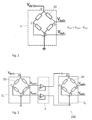
  • Fig. 1 shows a magnetic sensor 2 comprising four magnetic sensing elements 20 arranged in a full-bridge circuit, such as a Wheatstone bridge circuit. The magnetic sensing element 20 can comprise a magnetoresistive element, such as a magnetic tunnel junction. The differential output voltage Vout (Vout = Vout+ - Vout-) response under an external magnetic field vector H can be approximated to equation 1: V out a 0 + a 1 H a 3 H 3 V dd
    Figure imgb0001
    • where a0 is the sensor offset, a1, and a3 are the linear and 3rd order coefficients, respectively, and Vdd is the input bias voltage. Eq. 1 can be rewritten as: V out v s H V dd
      Figure imgb0002
    • where vs expresses the intrinsic dependence of the magnetic sensor when submitted to an external magnetic field (for example, vs does not depend on Vdd) (i.e., the normalized output voltage of the sensor): v s H = a 0 + a 1 H a 3 H 3
      Figure imgb0003
  • Usually a1 >> a3, which implies that output voltage Vout is, substantially linear with the applied field proportional to the input bias voltage Vdd.
  • The linearity of such magnetic sensors can generally be improved by the development of a magnetoresistive element, such as a magnetic tunnel junction, that ensures a linear Vout response and larger working magnetic field ranges. However, the improvement in linearity of the magnetoresistive element usually comes at the expense of a reduction of sensor sensitivity and magnetic field resolution.
  • Improving the linearity of the magnetic sensor without reduction of sensitivity has been proposed relying on the implementation of an integrated circuit (IC) configured to correct the non-linearities and obtain a high linear corrected output voltage Vcorr. International patent application number WO2021IB60743 by the present applicant describes a continuous compensation of next high order harmonic component of Vout by the implementation of an IC configured to generate a high non-linear voltage that continuously compensates the next high order harmonic component of Vout. Usually, the more complex is the IC the more linear is the corrected output voltage Vcorr, but at the expense of being more limited to work at high frequencies.
  • Other solutions can include using a lookup table or calculating a correction polynomial. Such solutions require the use of ADCs, DACs, memory, and a microcontroller and involve full digital reconstruction of Vcorr, usually with high power consumption, lower speed and large die area.
  • Summary
  • The present disclosure concerns a cascade magnetic sensor circuit comprising N magnetic sensors, wherein N equal to or greater than 2, wherein each magnetic sensor outputs an output voltage Voutn, the magnetic sensors being electrically connected in cascade with each other, wherein the output voltage Voutn of the nth magnetic sensor of the cascade magnetic sensor circuit supplies the input bias voltage Vdd_n+1 of the next magnetic sensor (n+1)th: V outn = V dd _ n + 1 ;
    Figure imgb0004
    and
    • wherein the output voltage of the nth magnetic sensor Voutn is proportional to the input bias voltage Vdd_n inputted to the nth magnetic sensor and to a normalized output voltage vs_n of the nth magnetic sensor depending on an external magnetic field vector H: V outn = v s _ n H V dd _ n ;
      Figure imgb0005
    • wherein the normalized output voltage vs_n expresses the intrinsic dependence of the magnetic sensor when submitted to the external magnetic field vector.
  • In an embodiment, the cascade sensor circuit is configured to generate a cascade output voltage: V outCascade = V dd n = 1 N v s _ n ,
    Figure imgb0006
    where VoutCascade is the cascade output voltage and Vdd is the bias voltage applied to the first magnetic sensor of the cascade magnetic sensor circuit.
  • In another embodiment, the cascade sensor circuit is configured to generate a cascade output voltage determined by: V outCascade = n = 1 N a n V outn ,
    Figure imgb0007
    where the Voutn is the voltage output of the nth magnetic sensor and an coefficient is independent of the external magnetic field vector and can be either positive or negative.
  • The cascade sensor circuit can be configured to correct high order components of a first output voltage Vout1 of the first magnetic sensor of the N magnetic sensors, and/or generate any desired polynomial output voltage response.
  • The present disclosure further concerns a magnetic sensor device for sensing an external magnetic field vector H and comprising the cascade magnetic sensor circuit. The magnetic sensor device is configured to output a corrected output voltage Vcorr of the magnetic sensor device that is determined by: V corr = a V outRef + b V outCascade ,
    Figure imgb0008
    where VoutRef is typically the output voltage of a magnetic sensor used as reference and the coefficients a and b are independent of the external magnetic field vector H.
  • The magnetic sensor device outputs a corrected output voltage having improved linearity with magnetic field amplitude and/or magnetic field orientation compared to the reference output voltage.
  • The magnetic sensor device can provide a linear signal without relying on CMOS processing, analog IC development, implementation and/or IC trimming. Instead, the cascade sensor compensates the non-linear coefficients of the output voltage of the magnetic sensor device, ensuring a linear magnetic sensor device with higher bandwidth operation
  • The magnetic sensor device can correct the output voltage for higher order components, such as 5th order and beyond to increase the magnetic field range operation or improve linearity. The magnetic sensor device has an improved linearity as a function of temperature and is compatible with a correction of the temperature coefficient of sensitivity.
  • The cascade sensor circuit can be configured to linearize and angular magnetic sensor therefore the magnetic sensor device has an improved linearity with respect to the orientation of the magnetic field, improving the working angular range of angular magnetic sensors for auto-focus (AF) applications.
  • Short description of the drawings
  • Exemplar embodiments of the invention are disclosed in the description and illustrated by the drawings in which:
    • Fig. 1 illustrates a magnetic sensor comprising four magnetic sensing elements arranged in a full-bridge circuit;
    • Fig. 2 shows a cascade sensor circuit, according to an embodiment;
    • Fig. 3 shows a cascade sensor device comprising three magnetic sensors, according to an embodiment;
    • Fig. 4 shows a general configuration of the cascade magnetic sensor circuit comprising N magnetic sensors, according to an embodiment;
    • Fig. 5 illustrates a magnetic sensor device for sensing an external magnetic field vector and comprises the cascade magnetic sensor circuit, according to an embodiment;
    • Fig. 6 shows a generic representation of the magnetic sensor device 10, according to an embodiment;
    • Fig. 7 illustrates an example of the magnetic sensor device of Fig. 6;
    • Fig. 8 shows the cascade output voltage of the cascade sensing circuit as a function of the reference output voltage for the magnetic sensor device of Fig. 5;
    • Fig. 8a shows the dependence of the linearity error of the corrected output voltage as a function of the bias voltage of the cascade sensing circuit;
    • Fig. 9a shows the reference output voltage VoutRef of a reference magnetic sensor as well as the corrected output voltage Vcorr of the magnetic sensor device of Fig.5 as a function of the applied magnetic field, when submitted to a bias voltage of 1V;
    • Fig. 9b show the linearity error of both the reference output voltage VoutRef of the reference magnetic sensor as well as the corrected output voltage Vcorr of the magnetic sensor device of Fig.5
    • Fig. 10a shows the dependence of the linearity error of the corrected output voltage of the magnetic sensor device of Fig. 7 as a function of the bias voltage of the cascade sensing circuit V0 when the bias voltage of the reference magnetic sensor Vdd equals 1V;
    • Fig. 10b shows the experimentally determined bias voltage of the cascade sensing circuit V0 necessary to obtain the lowest linearity error of the corrected output voltage of the magnetic sensor device of Fig.7 when the reference magnetic sensor is biased by 1V;
    • Figs. 11a and 11b show the sensitivity (Fig. 11a) and linearity error (Fig. 11b) of the reference output voltage of the reference magnetic sensor (VoutRef) and the corrected output voltage of the magnetic sensor device of Fig. 7 as a function of temperature;
    • Figs 12a report the third order coefficient as a function of temperature;
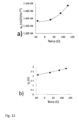
    • Fig. 12b shows a variation of the bias voltage of the cascade sensing circuit V0 of the magnetic sensor device of Fig.7 such that the linearity error is smaller than 0.08% at all temperature range;
    • Fig. 13 illustrates a 2D magnetic sensor device, according to an embodiment;
    • Fig. 14 shows the corrected output voltage (Fig. 14a), the reference output voltage (Fig. 14b) and the linearity error (Fig. 14c) with respect to the magnetic field orientation of the 2D magnetic sensor device of Fig.13;
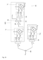
    • Fig. 15 illustrates a 2D magnetic sensor device, according to another embodiment;
    • Fig. 16 illustrates a cascade sensor circuit for generating a polynomial output voltage response, according to another embodiment.
    Examples of embodiments
  • Fig. 2 illustrates a cascade magnetic sensor circuit 100 according to an embodiment. The cascade magnetic sensor circuit 100 is shown comprising two magnetic sensors (2n=1, 2n=2 or 21, 22) electrically connected in cascade with each other.
  • It should be understood that the cascade magnetic sensor circuit 100 can comprise more than two magnetic sensors. More generally, the cascade magnetic sensor circuit 100 can comprise N magnetic sensors 2n, wherein N equal to or greater than 2, where the magnetic sensors 2n are electrically connected in cascade with each other. The output voltage Vout of the nth magnetic sensor of the cascade magnetic sensor circuit 2n (with n ≤ N) is proportional to the input bias voltage Vdd_n of the nth magnetic sensor 2n and to the normalized output voltage vs_n of the magnetic sensor 2n depending on the external magnetic field vector H, as defined by equation 3: V outn = v s _ n H V dd _ n
    Figure imgb0009
    where vs_n can be defined by equation 2b.
  • The output voltage Voutn of the nth magnetic sensor 2n supplies the input bias voltage Vdd_n+1 of the next magnetic sensor 2n+1. The cascade sensor circuit 100 generates therefore an output voltage VoutCascade, as defined by equation 4: V outCascade = V dd n = 1 N v s _ n
    Figure imgb0010
    where Vdd is the input bias voltage of the first magnetic sensor of the cascade sensor circuit.
  • In reference with Fig. 2, the cascade magnetic sensor circuit 100 comprises two magnetic sensor 2n, including a first magnetic sensor 21, the two magnetic sensor 2n are electrically connected in cascade. The first magnetic sensor 21 is configured to generate a first output voltage Vout_1 dependent on the external magnetic field vector H as described by equation 3.
  • The normalized output voltage vs_n (H) of the second magnetic sensor 2n can have a substantially identical dependence on the external magnetic field vector H as the normalized output voltage vs(H) of the first magnetic sensor 21. Therefore, the output voltage Voutn of the second magnetic sensor 2n is proportional to a degree n (here n= 2) with respect to the first output voltage Vout1 of the first magnetic sensor 21. In this embodiment, the cascade magnetic sensor circuit 100 outputs a cascade output voltage VoutCascade that corresponds to the output voltage Voutn of the second magnetic sensor 2n.
  • The first magnetic sensor 21 and the second magnetic sensor 2n can comprise four magnetic sensing elements 20 arranged in a full-bridge circuit, such as a Wheatstone bridge circuit. The magnetic sensing element 20 can comprise a magnetoresistive element, such as a magnetic tunnel junction. The first magnetic sensor 21 is electrically connected in cascade with the second magnetic sensor 2n such that the first differential output voltages Vout1+ and Vout1- of the first magnetic sensor 21 (nodes C and D) are respectively connected to the bias inputs (nodes A and B) of the second magnetic sensor 2n.
  • The first output voltage Vout1 is a differential output voltage that is equal to the difference between Vout1+ and Vout1- of the full-bridge circuit. The first output voltage Vout1 follows equations 2a, 2b and 3. When subjected to an external applied magnetic field H, the first magnetic sensor 21 produces the first output voltage Vout1 between points C and D and can be expressed by equation 4b: V out _ 1 = V out 1 + V out 1 = V dd v s _ 1 H
    Figure imgb0011
    where Vdd is the bias voltage applied to the first magnetic sensor 21 and vs_1(H) is the normalized output voltage of the first magnetic sensor 21 (described by Eq. 2b).
  • The second output voltage Voutn, where n=2, of the second magnetic sensor 2n can be expressed by equation 5a: V out 2 = V out 2 V out = V dd 2 v s _ 2 H
    Figure imgb0012
    where Vdd_2 and vs_2(H) are the input bias voltage and the normalized output voltage of the second magnetic sensor 22 respectively. However, in this cascade configuration, the output voltage Vout1 of the first magnetic sensor 21 is used as input bias voltage of the second magnetic sensor 2n (Vddn) . Therefore: V out 2 = V out 1 v s 2 H = V dd v s _ 1 H v s _ 2 H
    Figure imgb0013
  • If the second magnetic sensor 22 is configured to have a similar magnetic field vector dependence than the one of the first magnetic sensor 21 (v s_2 = vs_1 ), then: V out 2 = V dd v s _ 1 2 H V dd a 0 + a 1 H a 3 H 3 2
    Figure imgb0014
    or: V out 2 = V dd V out 1 2 V dd 2 = V out 1 2 / V dd
    Figure imgb0015
  • As equation 6b shows, the differential output voltage Vout2 of the second magnetic sensor 22 is quadratic with respect to the first output voltage Vout1 of the first magnetic sensor 21 in case that both magnetic sensors have a similar magnetic field dependence.
  • Fig. 3 shows the cascade sensor device 100 comprising three magnetic sensors 2n (N=3), in particular a first magnetic sensor 21 and two other magnetic sensors 22 and 23. The three magnetic sensors are electrically connected in cascade with each other. The differential output voltages Voutn+ and Voutn- of the nth magnetic sensor 2n can be respectively connected to the bias input of the following magnetic sensor (n+1) 2n+1. In this configuration, output voltage Vout3 of the third magnetic sensor 23 can be expressed by equation 7: V out 3 = V out 2 v s _ 3 H = V out 1 v s _ 2 H v s 3 H = V dd v s _ 1 1 H v s _ 2 H v s _ 3 H
    Figure imgb0016
  • The three magnetic sensors 2n can have a substantially identical dependence on the external magnetic field vector H (vs_1(H) = vs_2(H) = vs_3(H)) . For this configuration, the output voltage Vout3 of the third magnetic sensor can be expressed by equation 8a: V out 3 = V dd v s _ 1 1 3 H V dd a 0 + a 1 H a 3 H 3 3
    Figure imgb0017
    Equation 8a can also be rewritten as: V out 3 = V dd V out 1 3 V dd 3 = V out 1 3 / V dd 2
    Figure imgb0018
  • As shown in Eq. 8b, the output voltage Vout3 of the third magnetic sensor 23 is cubic with respect to the first output voltage Vout1 in case that the three magnetic sensors have a similar magnetic field dependence.
  • Therefore, for this configuration (Fig. 3) the cascade magnetic sensor circuit 100 outputs a cascade output voltage VoutCascade that corresponds to the output voltage of the third magnetic sensor 23.
  • Fig. 4.shows a more general configuration of the cascade magnetic sensor circuit 100 comprising a plurality of (here, more than three) magnetic sensors 2n electrically connected in cascade with each other. Here, the cascade magnetic sensor circuit 100 comprises N magnetic sensors 2n, where N > 3.
  • In this configuration, the cascade magnetic sensor circuit 100 outputs a cascade output voltage VoutCascade that corresponds to the output voltage VoutN of the Nth magnetic sensor 2N and is described by equation 4.
  • In the case that all the N magnetic sensors 2n of the cascade sensing circuit 100 have a substantially identical magnetic field vector dependence (vs_1(H) = vs_2(H) =...= vs_N(H)), then: V outCascade = V dd v s _ 1 1 N H V dd a 0 + a 1 H a 3 H 3 N
    Figure imgb0019
    Equation 9a can also be rewritten as: V outCascade = V dd V out 1 N V dd N = V out 1 N / V dd N 1
    Figure imgb0020
    In this configuration, each nth stage of the cascade sensing circuit 100 generates an output voltage Voutn that is proportional to the nth power of the first output voltage Vout1 of the first magnetic sensor 21 of the cascade sensing circuit 100.
  • Referring again to Fig. 2, the cascade sensor circuit 100 comprises an amplifier buffer 3 electrically connected between the differential output voltages Vout1+ and Vout1- (points C and D) of the first magnetic sensor 21 and the bias inputs (points A and B) of the magnetic sensor 2n. Referring to Figs. 3 and 4, the cascade sensor circuit 100 can further comprise an amplifier buffer 3 between the n-1 output voltage Voutn-1 of the n-1 magnetic sensor 2n-1 and the input of the n magnetic sensor 2n. The amplifier buffer 3 prevents the input impedance of a magnetic sensor 2n from loading the output impedance of the previous magnetic sensor 2n-1, which would cause undesirable loss of signal transfer.
  • Similar to the cascade magnetic sensor circuit 100 shown in Figs 2 and 3, the magnetic sensors 2n of the cascade magnetic sensor circuit 100 of Fig. 4 can comprise four magnetic sensing elements 20 arranged in a full-bridge circuit, such as a Wheatstone bridge circuit. The magnetic sensing element 20 can comprise a magnetoresistive element, such as a magnetic tunnel junction. For example, the magnetic sensing element 20 can comprise a magnetic tunnel junction comprising a reference layer having a reference magnetization and a sense layer having a sense magnetization that can be oriented relative to the reference magnetization, according to the orientation of the external magnetic field H.
  • The presented cascade magnetic sensor circuit 100 can be configured to improve the linearity of a magnetic sensor device for sensing the external magnetic field vector H.
  • In an embodiment illustrated in Fig. 5, a magnetic sensor device 10 for sensing an external magnetic field vector H comprises the cascade magnetic sensor circuit 100 including three magnetic sensors 2n (N = 3) connected in cascade. The output voltage Vout3 of the third magnetic sensor 23 can be used to compensate the non-linearity of the output voltage Vout1 of the first magnetic sensor 21. The output voltage Vout1 (differential output voltages Vout1+ and Vout1-) of the first magnetic sensors 21 is summed to the output voltage Vout3 (differential output voltages Vout3+ and Vout3-) of the third magnetic sensor 23 by a summing circuit 40. Each of the output voltages Vout1 and Vout3 can be electrically connected to a differential amplifier 42. In the case the three magnetic sensors 2n have a substantially identical dependence on the external magnetic field vector H, the corrected output voltage Vcorr of the magnetic sensor device 10 shown in Fig. 5 can be determined by equation 10: V corr = a V out + b V out 3
    Figure imgb0021
    where a and b are correction parameters independent of the external magnetic field vector H. By adjusting the values of a and b, the corrected output voltage Vcorr of the magnetic sensor device 10 shows an improved linearity compared to the first output voltage Vout1 of the first magnetic sensor 21.
  • In one aspect, the cascade magnetic sensor circuit 100 can further comprise an amplifier buffer at the output of each magnetic sensor of the cascade magnetic circuit 100. Fig. 6 shows a generic representation of the magnetic sensor device 10, according to an embodiment. The magnetic sensor device 10 comprises a cascade sensing circuit 100 and a reference magnetic sensor 2Ref configured to generate a reference output voltage VoutRef dependent on the external magnetic field vector H such that the corrected output voltage Vcorr of the magnetic sensor device 10 is determined by: V corr = a V outRef + b V outCascade
    Figure imgb0022
  • Note that for such a configuration, the reference magnetic sensor is biased by a voltage Vdd and the cascade sensing circuit 100 is biased by a voltage V0.
  • In the configurations of Figs. 1 to 5, the first magnetic sensor 21 can play the role of a reference magnetic sensor 2Ref and the reference magnetic sensor and the cascade sensing circuit are biased by the same bias voltage (V0 = Vdd). In the configuration of Fig. 6, the reference magnetic sensor 2Ref is arranged separately from the cascade sensing circuit 100. The reference output voltage VoutRef of the reference magnetic sensors 2Ref is summed to the cascade output voltage VoutCascade of the cascade sensing circuit 100 by a summing circuit 40.
  • Fig. 7 illustrates an example of the magnetic sensor device 10 of Fig. 6, where the cascade sensing circuit 100 comprises three magnetic sensors 2n. Each of the three magnetic sensors 2n and the reference magnetic sensor 2Ref comprises four magnetic sensing elements 20 arranged in a full-bridge circuit, such as a Wheatstone bridge circuit. The magnetic sensing element 20 can comprise a magnetoresistive element, such as a magnetic tunnel junction. The reference magnetic sensor 2Ref can be inputted by an input bias voltage Vdd such that the reference magnetic sensor 2Ref generates the first reference output voltage VoutRef dependent on the external magnetic field vector H. Because the response of the cascade sensing circuit 100 is proportional to the input bias voltage of the first magnetic sensor 21 of the cascade sensing circuit, the input bias voltage of the first magnetic sensor 21 of the cascade sensing circuit 100 can be referred to as the bias voltage of the cascade sensing circuit. The cascade sensing circuit 100 can be biased with an input bias voltage V0 such that the cascade sensing circuit 100 generates the cascade output voltage VoutCascade. Similar to the cascade sensing circuit 100 shown in Fig. 5, the cascade output voltage VoutCascade is generated by the output voltage Vout3 of the third (or last) magnetic sensor 23 of the cascade sensing circuit 100. The reference output voltage VoutRef of the reference magnetic sensor 2Ref is electrically connected to cascade output voltage VoutCascade via a summing circuit 40. Each of the output voltages, the cascade output voltage VoutCascade of the cascade sensing circuit 100, as well as the reference output voltage VoutRef of the reference magnetic sensor 2Ref, can be electrically connected to a differential amplifier 42.
  • In one aspect, the magnetic sensor device 10 can further comprise an amplifier buffer 3 at the output of each magnetic sensor of the magnetic sensor device.
  • In the case the magnetic sensing element 20 comprises a magnetic tunnel junction element and the reference magnetic sensor 2Ref is biased at Vdd, the reference output voltage VoutRef can be expressed by equation 12: V outRef = V dd v s _ Ref H V dd a 0 + a 1 H a 3 H 3
    Figure imgb0023
  • In the case where the magnetic sensors 2n of the magnetic sensor circuit 100 have a similar magnetic field vector dependence than the reference magnetic sensor the cascade output voltage VoutCascade can be expressed by equation 13: V outCascade = V ˙ 0 v s _ Ref H 3 V 0 a 0 + a 1 H a 3 H 3 3
    Figure imgb0024
  • By summing the reference output voltage VoutRef to the cascade output voltage VoutCascade, a corrected output voltage Vcorr is obtained: V corr = V outRef + V outCascade = V dd v s _ Ref H + V 0 V dd v s _ Ref H 3
    Figure imgb0025
  • Fig. 8 shows the cascade output voltage VoutCascade of the cascade sensing circuit 100 as a function of the reference output voltage VoutRef for the magnetic sensor device 10 of Fig. 5, when the input bias voltage Vdd applied at the reference magnetic sensor 2Ref and the input bias voltage V0 applied at the cascade sensing circuit 100 are Vdd = V0 = 1V. The output voltage generated by the cascade sensing circuit 100 VoutCascade (points) follows closely the cube of the reference output voltage VoutRef (continuous grey line) as expected by Eq. 8b. Fig. 8 shows therefore that the cascade sensing circuit 100 can provide a non-linear response that can be used to compensate the non-linearity of other voltage signals.
  • Fig. 9a shows the reference output voltage VoutRef (black curve) of the reference magnetic sensor 2Ref as a function of the applied magnetic field H, when submitted to an input bias voltage Vdd of 1V. The linearity error of the reference magnetic sensor 2Ref when submitted at magnetic fields up to ±47 mT is ~ 1.4% (curve VoutRef on Fig.9 b). On the other hand, the corrected output voltage Vcorr of a magnetic device 10 considering the same reference magnetic sensor biased by Vdd = 1V and a cascade sensing circuit 100 formed by three magnetic sensors 2n (as sketched in Fig. 7) when the cascade sensing circuit is biased at V0 = 2.4V is shown by the grey curve on Fig.9a. The linearity error of the corrected output voltage Vcorr is ~ 0.06 % (curve Vcorr in Fig. 9b) leading to a total reduction of linearity error of about 20 times.
  • In order to ensure a high linear response of the magnetic sensor device 10, the bias voltage applied to the cascade magnetic sensor circuit 100 (V0) must be proportional to the bias voltage applied to the reference magnetic sensor (Vdd), as shown by Eq. 15: V 0 = K a 1 a 3 V dd
    Figure imgb0026
    where K is a coefficient depending on the linear and third-order coefficients, a1 and a3 respectively, of the reference magnetic sensor response, as described by Eq. 2b.
  • From the reference output voltage VoutRef versus the applied magnetic field H curve of Fig.9a, the following values can be derived: a1 ~ 4.24 mV/V/mT and a3 ~ 1.4276 mVN/mT3. Thus, according to equation 15, the ratio V0/Vdd must be close to 2.17 for an optimal linear response of the magnetic sensor device 10 of Fig. 5, in good concordance with the obtained ratio of 2.4.
  • Fig. 10a shows the dependence of the linearity error of the corrected output voltage Vcorr as a function of the input bias voltage V0 when the input bias voltage Vdd equal 1V. The linearity error is minimum (~ 0.06%) at V0 = V0m = 2.4V and increases almost linearly with [V0 - V0m].
  • Fig. 10b shows the experimentally determined input bias voltage V0 of the cascade sensing circuit 100 necessary to obtain the lowest linearity error (~ 0.06%) of the corrected output voltage Vcorr of the reference magnetic sensor 2Ref when the reference magnetic sensor 2Ref is biased at Vdd. The ratio V0/Vdd is the same for the four measured points of experimentally determined input bias voltage V0, as predicted by equation 15.
  • The robustness of the linear response of the magnetic sensor device 10 of Fig. 7 as a function of temperature was evaluated. The response of the magnetic sensor device 10 for an applied magnetic field H of up to ± 50 mT at -40°C, 30°C, 85°C and 125°C was measured.
  • Figs. 11a and 11b show the sensitivity (Fig. 11a) and linearity error (Fig. 11b) of the reference magnetic sensor 2Ref of the magnetic sensor device 10 of Fig. 7 as a function of temperature (black dots). The temperature coefficient of sensitivity (TCS) is equal to about -420 ppm/C and the linearity error is between 1.56% - 1.78% through all the temperature range. Similarly, the sensitivity and linearity error of the temperature dependence of the corrected output voltage Vcorr from the magnetic sensor device 10 (see Fig. 7) is also plotted (open dots, showing a similar TCS of about -460 ppm/C and a linearity error between 0.06% and 0.25%. The input bias voltage V0 was kept constant (V0 ~ 2.4V) at all temperature ranges.
  • As shown in Figs 12a, the third order coefficient a3 is also temperature dependent. This implies that in order to fully optimize the linearity error of the magnetic sensor device 10, the input bias voltage V0 should be varied over temperature. Fig. 12b shows a possible variation of the input bias voltage V0 such that the linearity error is smaller than 0.08% at all temperature range (see square dots in Fig.11b). However, reasonable linearity error (< 0.3%) is obtained when keeping V0 constant over temperature.
  • The linear dependence of V0 with temperature highlights the possibility to contemplate a correction temperature such that the magnetic sensor device 10 has a low TCS, for example a TCS smaller than -100 ppm/C, a linearity error smaller than 0.1 % over the whole temperature range, and a sensitivity greater than 4 mV/V/mT for an applied magnetic field H up to 50 mT.
  • The cascade magnetic sensor circuit 100 and the magnetic sensor device 10 can also be implemented in 2D magnetic sensors (magnetic sensors sensitive to the orientation of the external magnetic field) or also called angular magnetic sensors to linearize its sinusoidal response. Such implementation can improve the working angular range of the 2D magnetic sensor for auto-focus (AF) applications or for developing a full analog 2D linear sensor.
  • According to this embodiment, Fig. 13 illustrates a 2D magnetic sensor device 10 with a linearized response with respect to the magnetic field orientation angle θ. The magnetic sensor device 10 comprises a cascade magnetic sensor circuit 100 with two 2D magnetic sensors 2n connected in cascade, where the first 2D magnetic sensor is used as a reference magnetic sensor.
  • At high level, the first 2D magnetic sensor 2n=1 or 2Ref follows a response with respect to the orientation θ of the external magnetic field vector H with respect to a certain predefined axis in a coordinate system. described by Eq. 16: V outRef = V SIN = V dd _ SIN A SIN sinθ
    Figure imgb0027
  • Similarly, the second 2D magnetic sensor 2n=2 follows a response with respect to the orientation θ of the external magnetic field vector H with respect to a certain predefined axis in a coordinate system described by Eq. 17: V COS = V dd _ COS A COS cosθ
    Figure imgb0028
    where Vdd_SIN and Vdd_COS are the bias voltage submitted to both magnetic sensors and ASIN and Acos are the normalized amplitude voltages of both signals. Note the normalized output voltage for both sensors are therefore: V s _ SIN = A SIN sinθ
    Figure imgb0029
    V s _ COS = A COS cosθ
    Figure imgb0030
    With this cascade configuration the output voltage of the first 2D magnetic sensor (VSIN) is used as the input bias voltage of the second 2D magnetic sensor 22. Therefore, the same bias voltage submitted to both magnetic sensors (Vdd =Vdd_SIN = Vdd_COS) considering similar normalized amplitude voltages (A = ASIN = Acos), the cascade output voltage of this system will be: V outCascade = = V dd A 2 sinθ cosθ
    Figure imgb0031
    By considering Eq.16 and Eq.19 in Eq.11, the corrected output voltage of this magnetic sensor device 10 is: V corr = V dd A a sinθ b sinθ cosθ
    Figure imgb0032
  • By adjusting the values of parameters a and b, the corrected output voltage Vcorr can show, up to a certain angle range, a linear dependence with respect to the orientation θ of the external magnetic field vector H.
  • Fig. 14a shows both the reference output voltage VoutRef and the corrected output voltage Vcorr with respect to the magnetic field orientation θ between [-45°, 45°]. For this case, a ~ 1.38 and b ~ 0.38/A. Linearity error with respect to the magnetic field orientation θ at this angle range for both VoutRef and Vcorr is shown in Fig.14b. Note that linearity error of Vcorr is ~ 0.1 % at this angular range, which is x 20 smaller than VoutRef. Fig. 14c, shows the impact of angle range on linearity error for both the reference 2D magnetic sensor (VoutRef) and the proposed magnetic sensor device 10 (Vcorr). Typically, a 2D magnetic sensor shows a linearity error ~ 0.1 % only for angular ranges between [-10°, 10°] and linearity error increases dramatically with angular range. On the other hand, magnetic sensor device 10 enables to obtain a similar linearity error by increasing the working angular range by about 4.5 times.
  • According to another embodiment, Fig. 15 illustrates an alternative 2D magnetic sensor device 10 with a linearized response with respect to the magnetic field orientation θ. In this case, however, the reference magnetic sensor 2Ref is not part of the cascade magnetic sensor circuit 100 as in Fig.14. Note, also that between two stages of the cascade magnetic sensor circuit 100 a differential amplifier 42 and an amplification 44 is used (amplification stage g).
  • Different other configurations of the 2D magnetic sensor device 10 described in Fig. 14 can be considered in order to obtain a similar improvement of the linearity error. The cascade sensor circuit 100 of Fig. 15 is configured so the output voltage Vout1 of the first magnetic sensors 21 of the cascade circuit 100 is subtracted from an additional voltage signal Vadd and then amplified by factor g. This signal is then used as the bias voltage of the 2nd magnetic sensor 22 Vdd_2 : V dd _ 2 = V add V out 1 g
    Figure imgb0033
    and to generate a cascade output voltage: V outCascade = V add V dd v s _ 1 g v s _ 2
    Figure imgb0034
  • Considering the SIN and COS response of the first and second magnetic sensor of the cascade sensor circuit 100 of Fig. 15, The corrected output voltage of this magnetic sensor device 10 can then be written as: V corr = a V dd A sinθ + b V add V 0 A cosθ g A sinθ
    Figure imgb0035
    where Vadd is the additional bias voltage used at the output of the first magnetic sensor and g is an amplification factor.
  • By adjusting the values of parameters a, b and amplification factor g as well as input bias voltages V0 and VA as: a ~ 1, V0 ~ Vdd, Vadd ~ A·Vdd and b·g~ 0.38/(A) the corrected output voltage Vcorr can show, up to a certain angle range, a similar linear dependence with respect to the orientation θ of the external magnetic field vector H than the previous embodiment shown in Fig. 14.
  • Finally, the cascade sensor circuit 100 can be configured not only to correct the high order component of a reference output voltage VoutRef but also to generate any desired polynomial output voltage response that might be useful for other purposes as sketched in Fig. 16.
  • For example, the cascade sensor circuit 100 can comprise N magnetic sensors 2n, wherein N equal to or greater than 2, and include a first magnetic sensor 21 and at least another magnetic sensor 2n electrically connected in cascade with each other. The first magnetic sensor 21 can be configured to generate a first output voltage Vout1 dependent on the external magnetic field vector H when submitted to an input bias voltage Vdd. The first output voltage Vout1 of the first magnetic sensor 21 can be used as a bias voltage of the next magnetic sensor 22. The N-1 output voltage VoutN-1 of the N-1 magnetic sensor 2N-1 can be used to bias voltage the N magnetic sensor 2N. The output of each magnetic sensor 2n is split so one part is used to biased the next magnetic sensor will the other part is amplified by a factor gn leading to a signal: V n = g n V outn
    Figure imgb0036
  • The cascade sensor circuit is configured to generate an output voltage VoutCascade determined by: V outCascade = n = 1 N V n = n = 1 N a n V outn
    Figure imgb0037
    where Voutn is the output voltage of the nth magnetic field sensor of the cascade sensor circuit and an is an amplification factor (or coefficient) independent of the external magnetic field vector H and can be either positive or negative.
  • Reference numbers and symbols
  • 10
    magnetic sensor device
    100
    cascade sensing circuit
    2
    magnetic sensor
    21
    first magnetic sensor
    2n
    nth magnetic sensor
    2R
    reference magnetic sensor
    20
    magnetic sensing element
    3
    amplifier buffer
    40
    summing circuit
    42
    differential amplifier
    44
    amplification
    θ
    magnetic field orientation angle
    H
    external magnetic field vector
    N
    number of magnetic sensors
    V0
    input bias voltage
    Vcorr
    corrected output voltage
    Vdd
    input bias voltage, input
    Vout
    output voltage
    Vout1
    first output voltage
    Voutn
    output voltage
    VoutRef
    reference output voltage
    VoutCascade
    cascade output voltage
    Vout1(H)
    normalized output voltage

Claims (16)

  1. A cascade magnetic sensor circuit (100) comprising N magnetic sensors (2n), each magnetic sensors (2n) generating an output voltage (Voutn), wherein N equal to or greater than 2, wherein the magnetic sensors (2n) are electrically connected in cascade with each other;
    wherein the output voltage (Voutn) of the nth magnetic sensors (2n) is proportional to an input bias voltage (Vdd_n) of the nth magnetic sensor (2n) and to a normalized output voltage (vs_n(H)) of the nth magnetic sensor (2n) depending on the external magnetic field vector (H): V outn = v s _ n H V dd _ n
    Figure imgb0038
    wherein the output voltage (Voutn) of one of the nth magnetic sensors (2n) supplies the input bias voltage (Vdd_n+1) of the (n+1)th magnetic sensor (2n+1).
  2. The cascade magnetic sensor circuit according to claim 1,
    wherein the cascade sensor circuit (100) is configured to generate an output voltage (VoutCascade): V outCascade = V dd n = 1 N v s _ n H ,
    Figure imgb0039
    where vs_n is the normalized output voltage of the nth magnetic sensor of the cascade magnetic sensor circuit and Vdd is the input bias voltage of the first magnetic sensor of the cascade magnetic sensor circuit.
  3. The cascade magnetic sensor circuit according to claim 1 or 2, comprising a first magnetic sensor (21) cascade connected to at least another magnetic sensor (2n);
    the normalized output voltage (vs_n(H)) of each magnetic sensor (2n) having a substantially identical dependence on the external magnetic field vector (H); and
    wherein the cascade magnetic sensor circuit (100) generates an output voltage (VoutCascade) that is proportional to a degree N with respect to the normalized output voltage (vs_1(H)) of the first magnetic sensor (21) and to the input bias voltage (Vdd) inputted to the first magnetic sensor (vout1): V outCascade = V dd v s _ 1 N H .
    Figure imgb0040
  4. The cascade magnetic sensor circuit according to claim 2 or 4, comprising an amplification (g) stage at the output of at least 1 of the N magnetic sensors of the cascade circuit, wherein the cascade sensor circuit (100) is configured to generate an output voltage (VoutCascade): V outCascade = V dd n = 1 N g n v s _ n H .
    Figure imgb0041
  5. The cascade magnetic sensor circuit according to claim 4, wherein an additional positive or negative voltage signal (Vadd) is added to the output voltage Voutn of at least one of the magnetic sensors (2n) of the cascade circuit (100) before amplification stage so the cascade sensor circuit is configured to generate an output voltage (VoutCascade).
  6. The cascade magnetic sensor circuit according to any one of claims 1 to 5,
    wherein all magnetic sensors comprises four magnetic sensing elements (20) arranged in a full-bridge circuit.
  7. The cascade magnetic sensor circuit according to claim 6, wherein the magnetic sensing element (20) comprises at least one magnetoresistive element, such as a magnetic tunnel junction.
  8. The cascade magnetic sensor circuit according to claim 1,
    wherein the cascade sensor circuit is configured to generate an output voltage (VoutCascade) determined by: V outCascade = n = 1 N a n V outn ,
    Figure imgb0042
    where the an coefficients are independent of the external magnetic field vector (H) and can be either positive or negative.
  9. The cascade magnetic sensor circuit according to any of claims 1 to 8,
    comprising a voltage buffer (3) at the output of each magnetic sensor of the cascade sensor circuit (100).
  10. A magnetic sensor device (10) for sensing an external magnetic field vector (H) and comprising the cascade magnetic sensor circuit (100) according to any one of claims 1 to 9 and at least one reference magnetic field sensor (2Ref);
    wherein a corrected output voltage (Vcorr) of the magnetic sensor device is determined by: V corr = a V outRef + b V outCascade ,
    Figure imgb0043
    where a and b are correction parameters independent of the external magnetic field vector (H), VoutRef is a reference output voltage generated by at least one reference magnetic sensor, the corrected output voltage (Vcorr) having improved linearity compared to the reference output voltage (VoutRef), and VoutCascade is the cascade output voltage of the cascade magnetic sensing circuit (100).
  11. The magnetic sensor device according to claim 10,
    wherein the cascade output voltage (VoutCascade) of the cascade magnetic sensing circuit (100) is electrically connected to the reference output voltage (VoutRef) of the reference magnetic sensor (2Ref) via a summing circuit (40) configured to sum the cascade output voltage (VoutCascade) to the reference output voltage (VoutRef); and
    wherein a corrected output voltage (Vcorr) of the magnetic sensor device is determined by: V corr = a V outRef + b V outCascade .
    Figure imgb0044
  12. The magnetic sensor device according to claim 11,
    wherein the cascade output voltage (VoutCascade) of the cascade magnetic sensing circuit (100) is electrically connected to the reference output voltage (VoutRef) of the reference magnetic sensor (2Ref) via a differential amplifier circuit (42) configured to subtract the cascade output voltage (VoutCascade) to the reference output voltage (VoutRef).
  13. The magnetic sensor device according to any one of claims 10 to 12,
    wherein the reference output voltage (VoutRef) is generated by least one of the magnetic sensors of the cascade magnetic sensing circuit (100).
  14. The magnetic sensor device according to any one of claims 10 to 12,
    wherein the reference magnetic sensor (2Ref) is an external magnetic sensor element from the cascade magnetic circuit (100).
  15. The magnetic sensor device according to any one of claims 10 to 14,
    wherein the reference magnetic sensor (2Ref) comprises four magnetic sensing elements (20) arranged in a full-bridge circuit.
  16. The magnetic sensor device according to any one of claims 10 to 15,
    comprising a voltage buffer (3) at the output of each magnetic sensor of the magnetic sensor device 10
EP22315165.5A 2022-07-22 2022-07-22 Cascade magnetic sensor circuit and a linear magnetic sensor device comprising the cascade magnetic sensor circuit Pending EP4310527A1 (en)

Priority Applications (3)

Application Number Priority Date Filing Date Title
EP22315165.5A EP4310527A1 (en) 2022-07-22 2022-07-22 Cascade magnetic sensor circuit and a linear magnetic sensor device comprising the cascade magnetic sensor circuit
PCT/IB2023/057466 WO2024018435A1 (en) 2022-07-22 2023-07-21 Linear magnetic sensor device comprising a cascade magnetic sensor circuit
US18/997,642 US20260029491A1 (en) 2022-07-22 2023-07-21 Cascade magnetic sensor circuit and a linear magnetic sensor device comprising the cascade magnetic sensor circuit

Applications Claiming Priority (1)

Application Number Priority Date Filing Date Title
EP22315165.5A EP4310527A1 (en) 2022-07-22 2022-07-22 Cascade magnetic sensor circuit and a linear magnetic sensor device comprising the cascade magnetic sensor circuit

Publications (1)

Publication Number Publication Date
EP4310527A1 true EP4310527A1 (en) 2024-01-24

Family

ID=82850298

Family Applications (1)

Application Number Title Priority Date Filing Date
EP22315165.5A Pending EP4310527A1 (en) 2022-07-22 2022-07-22 Cascade magnetic sensor circuit and a linear magnetic sensor device comprising the cascade magnetic sensor circuit

Country Status (3)

Country Link
US (1) US20260029491A1 (en)
EP (1) EP4310527A1 (en)
WO (1) WO2024018435A1 (en)

Citations (4)

* Cited by examiner, † Cited by third party
Publication number Priority date Publication date Assignee Title
DE102006025902A1 (en) * 2006-06-02 2007-12-06 Robert Bosch Gmbh Magnetic sensor e.g. speed sensor, arrangement for determining e.g. position, has two measuring bridges, where one bridge is arranged downstream in magnetic field, so that other bridge is used as electrical supply source for former bridge
EP2818884A1 (en) * 2012-02-20 2014-12-31 Jiangsu Multidimensional Technology Co., Ltd Magneto-resistive sensor for measuring magnetic field
WO2021060743A1 (en) 2019-09-24 2021-04-01 주식회사 엘지화학 Method for preparing graft polymer
WO2022144621A1 (en) * 2020-12-30 2022-07-07 Crocus Technology Inc. Linearization of magnetic sensor output based on continuous correction of high order voltage output components

Family Cites Families (2)

* Cited by examiner, † Cited by third party
Publication number Priority date Publication date Assignee Title
US9588134B2 (en) * 2012-05-10 2017-03-07 Infineon Technologies Ag Increased dynamic range sensor
JP2014163692A (en) * 2013-02-21 2014-09-08 Seiko Instruments Inc Magnetic sensor device

Patent Citations (4)

* Cited by examiner, † Cited by third party
Publication number Priority date Publication date Assignee Title
DE102006025902A1 (en) * 2006-06-02 2007-12-06 Robert Bosch Gmbh Magnetic sensor e.g. speed sensor, arrangement for determining e.g. position, has two measuring bridges, where one bridge is arranged downstream in magnetic field, so that other bridge is used as electrical supply source for former bridge
EP2818884A1 (en) * 2012-02-20 2014-12-31 Jiangsu Multidimensional Technology Co., Ltd Magneto-resistive sensor for measuring magnetic field
WO2021060743A1 (en) 2019-09-24 2021-04-01 주식회사 엘지화학 Method for preparing graft polymer
WO2022144621A1 (en) * 2020-12-30 2022-07-07 Crocus Technology Inc. Linearization of magnetic sensor output based on continuous correction of high order voltage output components

Non-Patent Citations (1)

* Cited by examiner, † Cited by third party
Title
BRAUN F ET AL: "A Chopper Stabilized Biasing Circuit Suitable for Cascaded Wheatstone-Bridge-Like Sensors", IEEE TRANSACTIONS ON CIRCUITS AND SYSTEMS PART I: REGULAR PAPERS, IEEE SERVICE CENTER, NEW YORK, NY, US, vol. 52, no. 8, 1 August 2005 (2005-08-01), pages 1653 - 1665, XP011137708, ISSN: 1057-7122, DOI: 10.1109/TCSI.2005.852022 *

Also Published As

Publication number Publication date
WO2024018435A1 (en) 2024-01-25
US20260029491A1 (en) 2026-01-29

Similar Documents

Publication Publication Date Title
US20240125624A1 (en) Position sensor devices, methods and systems based on magnetic field gradients
EP1720027A1 (en) Magnetic field detector, and current detection device, position detection device and rotation detection devices using the magnetic field detector
US10101410B2 (en) Methods and apparatus for sensor having fault trip level setting
JP5668224B2 (en) Current sensor
KR102945513B1 (en) Linearization of magnetic sensor output based on continuous correction of high-order voltage output components
EP3855127A1 (en) Single channel magnetoresistance-based angle sensor
US20230204693A1 (en) Magnetic field closed loop sensors with offset reduction
JP2007240202A (en) Magnetic detector and electronic compass using it
CN105277220A (en) Sensor system with a full bridge configuration of four resistive sensing elements
US20090012733A1 (en) Offset correction program and electronic compass
EP4310526A1 (en) Correction method for correcting the output voltage of a magnetic sensor
US9245547B1 (en) Magnetic sensor having enhanced linearization
Lopez-Martin et al. Performance tradeoffs of three novel GMR contactless angle detectors
WO2021176296A1 (en) Temperature compensated mtj-based sensing circuit for measuring an external magnetic field
EP4310527A1 (en) Cascade magnetic sensor circuit and a linear magnetic sensor device comprising the cascade magnetic sensor circuit
US11567108B2 (en) Multi-gain channels for multi-range sensor
JP6257019B2 (en) Magnetic sensor
JP7830092B2 (en) Magnetic sensor, electrical control device, correction method, and method for manufacturing a magnetic sensor
US11486734B2 (en) Magnetic sensor system and lens position detection device
KR100709363B1 (en) Magnetic detection apparatus and electronic orientation system using the same
EP4715411A2 (en) Sensor having translinear linearity compensation
US12517197B2 (en) Analog magnetic sensor device for measuring the orientation of an external magnetic field
US7443161B2 (en) Method of determining angles
US20250062726A1 (en) Sensor amplifier circuit
WO2024071016A1 (en) Sensor amplification circuit, sensor system, and sensor amplification circuit calibration method

Legal Events

Date Code Title Description
PUAI Public reference made under article 153(3) epc to a published international application that has entered the european phase

Free format text: ORIGINAL CODE: 0009012

STAA Information on the status of an ep patent application or granted ep patent

Free format text: STATUS: THE APPLICATION HAS BEEN PUBLISHED

AK Designated contracting states

Kind code of ref document: A1

Designated state(s): AL AT BE BG CH CY CZ DE DK EE ES FI FR GB GR HR HU IE IS IT LI LT LU LV MC MK MT NL NO PL PT RO RS SE SI SK SM TR

RAP1 Party data changed (applicant data changed or rights of an application transferred)

Owner name: CROCUS TECHNOLOGY SA

RAP1 Party data changed (applicant data changed or rights of an application transferred)

Owner name: ALLEGRO MICROSYSTEMS, LLC

STAA Information on the status of an ep patent application or granted ep patent

Free format text: STATUS: REQUEST FOR EXAMINATION WAS MADE

17P Request for examination filed

Effective date: 20240719

RBV Designated contracting states (corrected)

Designated state(s): AL AT BE BG CH CY CZ DE DK EE ES FI FR GB GR HR HU IE IS IT LI LT LU LV MC MK MT NL NO PL PT RO RS SE SI SK SM TR