EP4310510A1 - Pre-processing device and pre-processing method - Google Patents
Pre-processing device and pre-processing method Download PDFInfo
- Publication number
- EP4310510A1 EP4310510A1 EP22770920.1A EP22770920A EP4310510A1 EP 4310510 A1 EP4310510 A1 EP 4310510A1 EP 22770920 A EP22770920 A EP 22770920A EP 4310510 A1 EP4310510 A1 EP 4310510A1
- Authority
- EP
- European Patent Office
- Prior art keywords
- sample
- rack
- shaker
- adder
- additive
- Prior art date
- Legal status (The legal status is an assumption and is not a legal conclusion. Google has not performed a legal analysis and makes no representation as to the accuracy of the status listed.)
- Pending
Links
Images









Classifications
-
- G—PHYSICS
- G01—MEASURING; TESTING
- G01N—INVESTIGATING OR ANALYSING MATERIALS BY DETERMINING THEIR CHEMICAL OR PHYSICAL PROPERTIES
- G01N35/00—Automatic analysis not limited to methods or materials provided for in any single one of groups G01N1/00 - G01N33/00; Handling materials therefor
- G01N35/02—Automatic analysis not limited to methods or materials provided for in any single one of groups G01N1/00 - G01N33/00; Handling materials therefor using a plurality of sample containers moved by a conveyor system past one or more treatment or analysis stations
- G01N35/04—Details of the conveyor system
-
- G—PHYSICS
- G01—MEASURING; TESTING
- G01N—INVESTIGATING OR ANALYSING MATERIALS BY DETERMINING THEIR CHEMICAL OR PHYSICAL PROPERTIES
- G01N1/00—Sampling; Preparing specimens for investigation
- G01N1/28—Preparing specimens for investigation including physical details of (bio-)chemical methods covered elsewhere, e.g. G01N33/50, C12Q
- G01N1/40—Concentrating samples
- G01N1/405—Concentrating samples by adsorption or absorption
-
- G—PHYSICS
- G01—MEASURING; TESTING
- G01N—INVESTIGATING OR ANALYSING MATERIALS BY DETERMINING THEIR CHEMICAL OR PHYSICAL PROPERTIES
- G01N30/00—Investigating or analysing materials by separation into components using adsorption, absorption or similar phenomena or using ion-exchange, e.g. chromatography or field flow fractionation
- G01N30/02—Column chromatography
- G01N30/04—Preparation or injection of sample to be analysed
- G01N30/24—Automatic injection systems
-
- G—PHYSICS
- G01—MEASURING; TESTING
- G01N—INVESTIGATING OR ANALYSING MATERIALS BY DETERMINING THEIR CHEMICAL OR PHYSICAL PROPERTIES
- G01N35/00—Automatic analysis not limited to methods or materials provided for in any single one of groups G01N1/00 - G01N33/00; Handling materials therefor
- G01N35/00584—Control arrangements for automatic analysers
- G01N35/0092—Scheduling
-
- G—PHYSICS
- G01—MEASURING; TESTING
- G01N—INVESTIGATING OR ANALYSING MATERIALS BY DETERMINING THEIR CHEMICAL OR PHYSICAL PROPERTIES
- G01N35/00—Automatic analysis not limited to methods or materials provided for in any single one of groups G01N1/00 - G01N33/00; Handling materials therefor
- G01N35/0099—Automatic analysis not limited to methods or materials provided for in any single one of groups G01N1/00 - G01N33/00; Handling materials therefor comprising robots or similar manipulators
-
- G—PHYSICS
- G01—MEASURING; TESTING
- G01N—INVESTIGATING OR ANALYSING MATERIALS BY DETERMINING THEIR CHEMICAL OR PHYSICAL PROPERTIES
- G01N1/00—Sampling; Preparing specimens for investigation
- G01N1/28—Preparing specimens for investigation including physical details of (bio-)chemical methods covered elsewhere, e.g. G01N33/50, C12Q
- G01N1/38—Diluting, dispersing or mixing samples
-
- G—PHYSICS
- G01—MEASURING; TESTING
- G01N—INVESTIGATING OR ANALYSING MATERIALS BY DETERMINING THEIR CHEMICAL OR PHYSICAL PROPERTIES
- G01N35/00—Automatic analysis not limited to methods or materials provided for in any single one of groups G01N1/00 - G01N33/00; Handling materials therefor
- G01N2035/00465—Separating and mixing arrangements
- G01N2035/00495—Centrifuges
-
- G—PHYSICS
- G01—MEASURING; TESTING
- G01N—INVESTIGATING OR ANALYSING MATERIALS BY DETERMINING THEIR CHEMICAL OR PHYSICAL PROPERTIES
- G01N35/00—Automatic analysis not limited to methods or materials provided for in any single one of groups G01N1/00 - G01N33/00; Handling materials therefor
- G01N2035/00465—Separating and mixing arrangements
- G01N2035/00524—Mixing by agitating sample carrier
-
- G—PHYSICS
- G01—MEASURING; TESTING
- G01N—INVESTIGATING OR ANALYSING MATERIALS BY DETERMINING THEIR CHEMICAL OR PHYSICAL PROPERTIES
- G01N30/00—Investigating or analysing materials by separation into components using adsorption, absorption or similar phenomena or using ion-exchange, e.g. chromatography or field flow fractionation
- G01N30/02—Column chromatography
- G01N30/04—Preparation or injection of sample to be analysed
- G01N30/06—Preparation
-
- G—PHYSICS
- G01—MEASURING; TESTING
- G01N—INVESTIGATING OR ANALYSING MATERIALS BY DETERMINING THEIR CHEMICAL OR PHYSICAL PROPERTIES
- G01N35/00—Automatic analysis not limited to methods or materials provided for in any single one of groups G01N1/00 - G01N33/00; Handling materials therefor
- G01N35/00584—Control arrangements for automatic analysers
- G01N35/00594—Quality control, including calibration or testing of components of the analyser
- G01N35/00693—Calibration
Definitions
- the present invention relates to a pre-processing device and a pre-processing method.
- Patent Document 1 describes an automatic analysis system including a plurality of automatic analysis devices and a sample transport device.
- Each automatic analysis device includes a belt conveyor and a sampling-analyzer, and also includes a sample introduction mechanism for introducing a specimen rack on the belt conveyor to the sampling-analyzer.
- the starting end of the rear conveyor is arranged close to the terminal end of the front conveyor.
- the sample transport device includes a transport mechanism, and is arranged between the front conveyor and the rear conveyor.
- the transport mechanism of the specimen transport device holds the specimen rack at the terminal end of the front conveyor and conveys the rack to the starting end of the rear conveyor.
- Pre-processing may be performed on a sample before the sample is analyzed in an analysis device. Similarly to the analysis of a sample, it is desired that the pre-processing for a sample is performed automatically. However, since the pre-processing includes a large number of processes, it is not easy to perform the pre-processing on a large number of samples while improving a throughput.
- An object of the present invention is to provide a pre-processing device and a pre-processing method that enable execution of pre-processing on a large number of samples while improving a throughput.
- One aspect of the present invention relates to a pre-processing device that performs pre-processing on a plurality of samples that are sequentially introduced and includes a first adder that adds a first additive to each sample, a second adder that adds a second additive to each sample, a shaker that shakes each sample, and a controller that controls operations of the first adder, the second adder and the shaker such that addition of the first additive, first-time shaking, addition of the second additive and second-time shaking are carried out sequentially with respect to a same sample, wherein the plurality of samples include a first sample, a second sample and a third sample that are introduced in this order, and the controller controls operations of the first adder, the second adder and the shaker such that the first-time shaking for the second sample is carried out in parallel with addition of the first additive to the third sample.
- Another aspect of the present invention relates to a pre-processing method of performing pre-processing on a plurality of samples that are sequentially introduced, including the steps of sequentially adding a first additive to the plurality of samples by using a first adder, sequentially carrying out first-time shaking by using a shaker with respect to the plurality of samples to which the first additive has been added, sequentially adding a second additive by using a second adder to the plurality of samples on which the first-time shaking has been carried out, and sequentially carrying out second-time shaking by using the shaker with respect to the plurality of samples to which the second additive have been added, wherein the plurality of samples include a first sample, a second sample and a third sample that that are introduced in this order, and the first-time shaking for the second sample is carried out in parallel with addition of the first additive to the third sample.
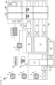
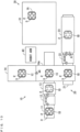
- Fig. 1 is a schematic diagram showing the pre-processing device according to one embodiment of the present invention.
- a plurality of racks 1, a plurality of racks 4 and a plurality of racks 7 are introduced into the pre-processing device 100.
- Each rack 1 holds a plurality (four in the present example) of sample bottles 2.
- a sample bottle 2 is a centrifuge tube, for example, and contains a sample.
- a screw-type cap 3 is attached to the upper portion of each sample bottle 2.
- Each rack 4 holds a plurality of dSPE (distributed solid phase extraction) tubes 5.
- a screw-type cap 6 is attached to the upper portion of each dSPE tube 5.
- a rack 7 holds a plurality of vials 8.
- the pre-processing device 100 performs pre-processing on a sample in each sample bottle 2 held in the rack 1 using the QuEChERS method. Further, the pre-processing device 100 supplies a pre-processed sample to an analysis device such as a gas chromatograph (GC) or a liquid chromatograph (LC). Specifically, the pre-processing device 100 includes a first adding unit 10, a second adding unit 20, a centrifugation unit 30, robot arms 40, 50, 60, transport units 70, 80 and a controller 90.
- GC gas chromatograph
- LC liquid chromatograph
- the first adding unit 10 includes a transporter 11, an attacher-detacher 12, an adder 13 and a shaker 14.
- the plurality of racks 1 are sequentially introduced into the transporter 11.
- the transporter 11 includes a belt conveyor and transports an introduced rack 1 in one direction or its opposite direction in the first adding unit 10.
- the attacher-detacher 12 attaches a cap 3 to each sample bottle 2 or detaches a cap 3 from each sample bottle 2 by rotating the cap 3 of each sample bottle 2 held by the rack 1.
- the adder 13 is an example of a first adder, and injects a solvent into each sample bottle 2 in the rack 1 and adds an internal standard (internal standard substance) as a first additive.
- the solvent is acetonitrile, for example.
- the plurality of racks 1 on which the processing has been performed by the adder 13 or the plurality of racks 1 on which the processing has been performed by the second adding unit 20 are sequentially introduced into the shaker 14.
- the shaker 14 stirs the contents of each sample bottle 2 by shaking an introduced rack 1.
- the second adding unit 20 includes a transporter 21, an attacher-detacher 22 and an adder 23.
- the plurality of racks 1 are sequentially introduced into the transporter21 from the first adding unit 10.
- the transporter 21 has the configuration similar to that of the transporter 11, and transports an introduced rack 1 in the second adding unit 20.
- the attacher-detacher 22 has the configuration similar to that of the attacher-detacher 12, and attaches a cap 3 to or detaches a cap 3 from each sample bottle 2 held by the rack 1.
- the adder 23 is an example of a second adder, and adds predetermined powder as a second additive to each sample bottle 2 in the rack 1.
- the centrifugation unit 30 includes a separator 31, transporters 32, 33 and attacher-detachers 34, 35.
- the plurality of racks 1 are sequentially introduced into the separator 31 from the first adding unit 10.
- the separator 31 the plurality (four, for example) of racks 1 are arranged at equal angular intervals.
- the separator 31 is an example of a first separator and includes a centrifuge. The separator 31 separates the contents of each sample bottle 2 in the plurality of racks 1 into components by applying a centrifugal force to the plurality of introduced racks 1.
- the transporters 32, 33 and are examples of first and second transporters, respectively, and have the configuration similar to that of the transporter 11.
- the transporters 32, 33 are arranged in parallel to each other and alternately transports the plurality of racks 1 introduced into the separator 31 in the centrifugation unit 30.
- the attacher-detachers 34, 35 are examples of first and second attacher-detachers, respectively, and have the configuration similar to that of the attacher-detacher 12.
- the attacher-detachers 34, 35 are arranged to correspond to the transporters 32, 33, respectively, and attach a cap 3 to or detach a cap 3 from each sample bottle 2 held in the racks 1 respectively transported by the transporters 32, 33.
- the robot arm 40 is an example of a robot arm, and holds and transports a rack 1 among the first adding unit 10, the second adding unit 20 and the centrifugation unit 30. In this case, it is possible to transport each rack 1 without causing the rack 1 to interfere with another rack 1. Thus, as described below, the processes for the plurality of racks 1 can be performed in parallel.
- the robot arm 40 includes two arm portions. One arm portion transports a rack 1 among the transporter 11, the shaker 14 and the transporter 21. The other arm portion transports a rack 1 among the transporter 11, and a transporter (not shown), the separator 31 and the transporters 32, 33 of the centrifugation unit 30.
- the robot arm 50 is one example of a dispenser and is provided among the centrifugation unit 30 and the transport units 70, 80.
- a pipette capable of sucking a sample is attached to the robot arm 50.
- the robot arm 50 sucks a relatively large amount of sample as a sample for a GC from a sample bottle 2 in a rack 1 transported by the transporters 32, 33 of the centrifugation unit 30, and injects the sample into a dSPE tube 5 held by the rack 4 in the transport unit 70. Further, the robot arm 50 sucks the sample for a GC from the dSPE tube 5 after centrifugation is carried out and injects the sample into a vial 8 held by the rack 7. Thus, the sample is dispensed.
- the robot arm 60 is another example of a dispenser and is provided among the centrifugation unit 30 and the transport units 70, 80.
- a pipette capable of sucking a sample is attached to the robot arm 60.
- the robot arm 60 sucks a relatively small amount of sample as a sample for an LC from a sample bottle 2 in a rack 1 transported by the transporters 32, 33 of the centrifugation unit 30, and injects the sample into a vial 8 held by the rack 7 in the transport unit 80.
- the sample is dispensed.
- the transport unit 70 includes a transporter 71, an attacher-detacher 72, a shaker 73 and a separator 74.
- a plurality of racks 4 are sequentially introduced into the transporter 71.
- the transporter 71 has the configuration similar to that of the transporter 11.
- the transporter 71 transports the plurality of introduced racks 4 in the transport unit 70.
- Each dSPE tube 5 in a rack 4 contains a filler for removing impurities (cleanup).
- the attacher-detacher 72 has the configuration similar to that of the attacher-detacher 12, and attaches a cap 6 to or detaches a cap 6 from each dSPE tube 5 held by a rack 4 by rotating the cap 6 of each dSPE tube 5 held by the rack 4.
- a supernatant liquid in a sample bottle 2 in a rack 1 containing a sample is dispensed into a dSPE tube 5 by the robot arm 50.
- the shaker 73 has the configuration similar to that of the shaker 14, and stirs the contents of a dSPE tube 5 by shaking an introduced rack 4.
- the plurality of racks 4 on which the processing has been performed by the shaker 73 are sequentially introduced into the separator 74.
- the separator 74 is an example of a second separator and has the configuration similar to that of the separator 31.
- the separator 74 separates the contents of a plurality of dSPE tubes 5 in each rack 4 into components by applying a centrifugal force to the plurality of introduced racks 4.
- the rack 4 on which the processing has been performed by the separator 74 is transported to the robot arm 50 by the transporter 71.
- the transport unit 80 includes transporters 81, 82 and a compression filtration unit 83.
- a plurality of racks 7 are sequentially introduced into the transporters 81, 82.
- the transporters 81, 82 have the configuration similar to that of the transporter 11 and are arranged in parallel to each other.
- the transporter 81 transports a rack 7 holding vials 8 for an LC in the transport unit 80.
- the transporter 82 transports a rack 7 holding vials 8 for a GC in the transport unit 80.
- a supernatant liquid in a sample bottle 2 in a rack 1 including a sample is dispensed into each vial 8 for an LC in a rack 7 by the robot arm 60 in the transporter 81.
- a vial 8 for an LC is Mini-UniPrep, for example.
- the rack 7 is transported to the compression filtration unit 83 by the transporter 81, and compression filtration for vials 8 for an LC is carried out in the compression filtration unit 83.
- a sample for an LC is completed.
- the rack 7 holding vials 8 containing the sample for an LC is transported to an analysis device by the transporter 81.
- a supernatant liquid in a dSPE tube 5 for which centrifugation has been carried out in the transport unit 70 is dispensed into each vial 8 for a GC in a rack 7 by the robot arm 50 in the transporter 82.
- a sample for a GC is completed.
- a rack 7 holding vials 8 containing the sample for a GC is transported to an analysis device by the transporter 82.
- the controller 90 includes a Central Processing Unit (CPU), for example.
- the controller 90 controls the operations of the first adding unit 10, the second adding unit 20, the centrifugation unit 30, the robot arms 40, 50, 60 and the transport units 70, 80.
- CPU Central Processing Unit
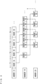
- Fig. 2 is a time table showing the operations of the first adding unit 10 and the second adding unit 20. As shown in Fig. 2 , in a plurality of successive periods T1 to T4, the racks 1A to 1D are respectively introduced into the first adding unit 10, and the processing for the introduced racks 1A to 1D is started.
- the processing performed by the adder 13 takes a relatively long period of time.
- the processing for the rack 1A is performed by the adder 13.
- the processing for the rack 1A is performed by the shaker 14 in parallel.
- the processing for the rack 1B which is one rack before the rack 1C, performed by the shaker 14 and the processing for the rack 1A, which is two racks before the rack 1C, performed by the adder 23 are performed in parallel.
- the processing for the rack 1A is performed by the shaker 14 while the processing for the rack 1C performed by the adder 13 is in progress.
- the processing for the rack 1C which is one rack before the rack 1D, performed by the shaker 14 and the processing for the rack 1B, which is two racks before the rack 1D, performed by the adder 23 are performed in parallel. Further, after the processing for the rack 1C performed by the shaker 14 and the processing for the rack 1B performed by the adder 23 are finished, the processing for the rack 1B is performed by the shaker 14 while the processing for the rack 1D performed by the adder 13 is in progress. Thereafter, the similar operation is repeated.
- the period of time in which addition of an internal standard by the adder 13 is carried out is preferably longer than 60 seconds.
- the period of time in which addition of an internal standard is carried out is 90 seconds. This is because, when 200 ⁇ L of solvent (acetonitrile, for example) containing an internal standard and 5 mL to 10 mL of solvent (acetonitrile, for example) are added, if the solvents are added in a period of time less than 60 seconds, bubbles are generated, and accuracy of a subsequent analysis performed by an analysis device such as a liquid chromatograph may be adversely affected.
- the period of time required for addition may be less than 60 seconds, such as 50 seconds.
- the period of time required for shaking by the shaker 14 is 60 seconds, for example. 60 seconds for this period of time is defined in the protocol for the QuEChERS method. 10 seconds is required for addition of powder by the adder 23, for example.
- the reason why powder can be added in a shorter period of time than the period of time required for addition of an internal standard by the adder 13 is because only a pre-measured amount of powder may be added.
- the period of time required for addition of powder by the adder 23 may be longer than 10 seconds.
- the first feature of the present invention is that, during the period (T3) in which addition of an internal standard to a rack (the rack 1C, for example) by the adder 13 is carried out, shaking for a rack (the rack 1B, for example), which is one rack before the rack (the rack 1C, for example), is carried out in parallel.
- This can shorten the processing period of time required for the entire pre-process.
- it is considered that, after addition of an internal standard by the adder 13 and subsequent first-time shaking by the shaker 14 are carried out for the rack 1B, for example, addition of an internal standard by the adder 13 and the first-time shaking by the shaker 14 are carried out for the next rack 1C.
- This comparative example is based on the idea that addition and shaking are combined into one processing process.
- the processing period of time is lengthened by the period of time required for the first-time shaking by the shaker 14.
- addition of an internal standard by the adder 13 to the rack 1C, which is one rack after the rack 1B, is carried out in parallel with the first-time shaking for the rack 1B, which is one rack before the rack C1, by the shaker 14.
- the processing period of time can be shortened by the period of time required for the first-time shaking by the shaker 14.
- Another feature of the present invention is that, during the period in which addition of an internal standard to a rack (the rack 1C, for example) by the adder 13 is carried out, and after the first-time shaking for a rack (the rack 1B, for example), which is one rack before the rack 1C, by the shaker 14 is finished, the second-time shaking for a rack (the rack 1A, for example), which is two racks before the rack 1C, by the shaker 14 is carried out.
- a waiting period of time of 70 seconds is provided after addition of an internal standard.
- the shaker 14 Before the second-time shaking for a rack (the rack 1A, for example), which is two racks before a rack (the rack 1C), by the shaker 14 is carried out, second addition to the rack (the rack 1A, for example), which is two racks before the rack 1C, needs to be finished.
- second addition to a rack (the rack 1A, for example), which is two racks before a rack (the rack 1C), by the adder 23 is carried out during a period in which addition of an internal standard to the rack (the rack 1C, for example) by the adder 13 is carried out and in parallel with the first-time shaking of a rack (the rack 1B, for example), which is one rack before the rack (the rack 1C), by the shaker 14.
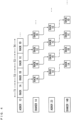
- FIG. 3 is a diagram showing the time table of the first modified example.
- a change is made such that second addition to a rack (the rack 1A, for example) by the adder 23 is carried out before addition of an internal standard to a rack (the rack 1C, for example) by the adder 13 is started.
- the second addition to the rack (the rack 1A, for example) by the adder 23 is carried out during addition of an internal standard to a rack (the rack 1B, for example) by the adder 13, or while the adder 13 waits (that is, during the period T2) after the addition of an internal standard to the rack (the rack 1B, for example) by the adder 13.
- Fig. 4 is a diagram showing the time table of a second modified example.
- the first-time shaking and the second-time shaking are carried out only by the one shaker 14.
- a dedicated shaker 14B for carrying out the second-time shaking is separately provided.
- Fig. 5 is a diagram showing the time table of a third modified example.
- the third modified example as compared with Fig. 2 or Fig. 3 , during addition of an internal standard to a rack (the rack 1C, for example) by the adder 13, shaking of a rack (the rack 1B, for example), which is one rack before the rack (the rack 1C), by the shaker 14 and addition of powder to a rack (the rack 1A, for example), which is two racks before the rack (the rack 1C), by the adder 23 are carried out in parallel.
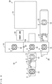
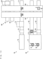
- Fig. 6 is a diagram for explaining the operations of the first adding unit 10 and the second adding unit 20 in the first period T1.
- the rack 1A is introduced into the transporter 11 of the first adding unit 10.
- the transporter 11 transports the rack 1A to the attacher-detacher 12.
- the attacher-detacher 12 detaches a cap 3 from each sample bottle 2 in the rack 1A and holds the detached cap 3.
- the transporter 11 transports the rack 1A to the adder 13.
- the adder 13 adds an internal standard to each sample bottle 2 in the rack 1A.
- the transporter 11 transports the rack 1A to the attacher-detacher 12.
- the attacher-detacher 12 attaches a held cap 3 to each sample bottle 2 in the rack 1A.
- Fig. 7 is a diagram for explaining the operations of the first adding unit 10 and the second adding unit 20 in the second period T2.
- the rack 1B is introduced into the transporter 11 of the first adding unit 10. Further, the transporter 11 transports the rack 1A to the shaker 14.
- the shaker 14 shakes the rack 1A. After shaking is finished, as indicated by the arrow A4, the shaker 14 places the rack 1A in a predetermined placement portion (an arm portion 14a of the shaker 14). Meanwhile, the processing similar to the processing for the rack 1A in Fig. 6 is performed on the rack 1B.
- Figs. 8 and 9 are diagrams for explaining the operations of the first adding unit 10 and the second adding unit 20 in the third period T3.
- the rack 1C is introduced into the transporter 11 of the first adding unit 10.
- the robot arm 40 transports the rack 1A to the transporter 21 of the second adding unit 20, and the transporter 11 transports the rack 1B to the shaker 14.
- the transporter 21 transports the rack 1A to the attacher-detacher 22.
- the attacher-detacher 22 detaches a cap 3 from each sample bottle 2 in the rack 1A and holds the detached cap 3.
- the transporter 21 transports the rack 1A to the adder 23.
- the adder 23 adds powder to each sample bottle 2 in the rack 1A.
- the transporter 21 transports the rack 1A to the attacher-detacher 22.
- the attacher-detacher 22 attaches a held cap 3 to each sample bottle 2 in the rack 1A.
- the processing similar to the processing for the rack 1A in Fig. 7 is performed on the rack 1B. Further, the processing similar to the processing for the rack 1B in Fig. 7 is performed on the rack 1C. Although the processing for the rack 1B performed by the shaker 14 is finished at a point in time at which the processing for the rack 1A performed by the adder 23 is finished, the processing for the rack 1C performed by the adder 13 is in progress.
- the robot arm 40 transports the rack 1A to the shaker 14 of the first adding unit 10.
- the shaker 14 shakes the rack 1A.
- the processing for the rack 1C is performed in parallel by the adder 13.
- a cap 3 is attached to each sample bottle 2 in the rack 1C by the attacher-detacher 12.
- Fig. 10 is a diagram for explaining the operations of the first adding unit 10 and the second adding unit 20 in the fourth period T4.
- the rack 1D is introduced into the transporter 11 of the first adding unit 10.
- the robot arm 40 transports the rack 1A to the separator 31 of the centrifugation unit 30 using one arm portion.
- the robot arm 40 transports the rack 1B to the transporter 21 of the second adding unit 20 using the other arm portion, and the transporter 11 transports the rack 1C to the shaker 14.
- Figs. 11 to 13 are diagrams for explaining the operations of the centrifugation unit 30 and the transport unit 70.
- a predetermined number of racks 1 are introduced into the separator 31 of the centrifugation unit 30.
- the separator 31 applies a centrifugal force to the plurality of introduced racks 1.
- the transporter 32 transports the rack 1A to the attacher-detacher 34.
- the attacher-detacher 34 detaches a cap 3 from each sample bottle 2 in the rack 1A and holds the detached cap 3.
- the transporter 32 transports the rack 1A to the robot arm 50 or the robot arm 60.
- part of a sample in each sample bottle 2 held by the rack 1A is used as a sample for an LC, and the other part is used as a sample for a GC.
- the transporter 81 transports a rack 7 to the robot arm 60 in the transport unit 80.
- the robot arm 60 sucks the contents from a plurality of sample bottles 2 in the rack 1A in the transporter 32 and injects the contents into a plurality of vials 8 in the rack 7 in the transporter 81.
- the transporter 81 transports the rack 7 to the compression filtration unit 83. Further, a new rack 7 is introduced into the transporter 81.
- the transporter 71 transports a rack 4 to the robot arm 50 in the transport unit 70.
- the attacher-detacher 72 detaches a cap 6 from each dSPE tube 5 in the rack 4 and holds the detached cap 6.
- the transporter 82 transports a rack 7 to the robot arm 50.
- the robot arm 50 sucks the contents from the plurality of sample bottles 2 in the rack 1A in the transporter 32 and injects the contents into the plurality of dSPE tubes 5 in the rack 4 in the transporter 71. Thereafter, the attacher-detacher 72 attaches a held cap 6 to each dSPE tube 5 in the rack 4.
- the transporter 71 transports the rack 4 to the shaker 73.
- the shaker 73 shakes the rack 4.
- a shaking operation is performed on each dSPE tube 5 in the rack 4.
- the transporter 71 transports the rack 4 to the separator 74.
- the separator 74 applies a centrifugal force to the introduced racks 4.
- centrifugation is carried out.
- the attacher-detacher 72 detaches a cap 6 from each dSPE tube 5 in the rack 4 and holds the detached cap 6. Further, the transporter 71 sequentially transports the racks 4 to the robot arm 50.
- the robot arm 50 sucks the contents from the plurality of dSPE tubes 5 on which centrifugation has been carried out and injects the contents into the plurality of vials 8 in the rack 7 in the transporter 82.
- the transporter 82 transports the rack 7 to an analysis device.
- the attacher-detacher 72 attaches a held cap 6 to each dSPE tube 5 in the rack 4 for which dispensing has been finished.
- the transporter 71 transports the used rack 4 to a discarding device (not shown). Further, a new rack 4 is introduced into the transporter 71, and a new rack 7 is introduced into the transporter 82.
- the transporter 33 transports the rack 1B to the attacher-detacher 35.
- the attacher-detacher 35 detaches a cap 3 from each sample bottle 2 in the rack 1B and holds the detached cap 3.
- the processing for the rack 1B can be started immediately.
- the transporter 32 transports the rack 1A to the attacher-detacher 34, and the transporter 33 transports the rack 1B to the robot arm 50 or the robot arm 60.
- the attacher-detacher 34 attaches a held cap 3 to each sample bottle 2 in the rack 1A. Thereafter, the transporter 32 transports the rack 1A to the discarding device (not shown).
- the processing similar to the processing for the rack 1A in Figs. 11 and 12 is performed on the rack 1B. Further, during a period in which the processing for the rack 1B is performed, the transporter 32 transports the rack 1C to the attacher-detacher 34. The attacher-detacher 34 detaches a cap 3 from each sample bottle 2 in the rack 1C and holds the detached cap 3. Thus, after the processing for the rack 1B is finished, the processing for the rack 1C can be started immediately. Thereafter, the similar processing is repeated for the following rack 1.
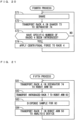
- Fig. 14 is a diagram showing the entire process of the pre-processing performed by the pre-processing device 100.
- a unique hatching pattern or dot pattern is applied to a rectangle indicating each process.
- the pre-processing includes first to fifth processes.
- the first process after addition of an internal standard and shaking are carried out, addition of powder and shaking are carried out.
- a sample is separated.
- a sample for an LC is dispensed into a vial 8
- compression filtration for the sample for an LC is carried out
- a sample for a GC is dispensed into a dSPE tube 5.
- the sample for a GC in the dSPE tube 5 is shaken and separated.
- the sample for a GC is dispensed into a vial 8.
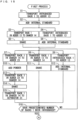
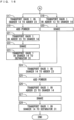
- Figs. 15 and 16 are flowcharts showing the first process.
- the plurality of racks 1 are sequentially introduced into the transporter 11 of the first adding unit 10 by a transport device (not shown).
- the transporter 11 transports a newly introduced rack 1 to the adder 13 (step S1).
- the adder 13 adds an internal standard to each sample bottle 2 in the rack 1 transported in the step S1 (step S2).
- the transporter 11 transports the rack 1 in the adder 13 to the shaker 14 (step S3). Further, the transporter 11 transports a newly introduced rack 1 to the adder 13 similarly to the step S1 (step S4).
- the shaker 14 shakes the rack 1 transported in the step S3 (step S5).
- the adder 13 adds an internal standard to each sample bottle 2 in the rack 1 transported in the step S4 similarly to the step S2 (step S6).
- the steps S3 and S5 are executed in parallel with the steps S4 and S6.
- the robot arm 40 transports the rack 1 in the shaker 14 to the adder 23 of the second adding unit 20 (step S7).
- the transporter 11 transports the rack 1 in the adder 13 to the shaker 14 (step S8).
- the transporter 11 transports a newly introduced rack 1 to the adder 13 similarly to the step S4 (step S9).
- the adder 23 adds powder to each sample bottle 2 in the rack 1 transported in the step S7 (step S10). Similarly to the step S5, the shaker 14 shakes the rack 1 transported in the step S8 (step S11). Similarly to the step S6, the adder 13 adds an internal standard to each sample bottle 2 in the rack 1 transported in the step S9 (step S12).
- the robot arm 40 transports the rack 1 in the adder 23 to the shaker 14 of the first adding unit 10 (step S13).
- the shaker 14 shakes the rack 1 transported in the step S13 (step S14).
- the robot arm 40 transports the rack 1 in the shaker 14 to the separator 31 of the centrifugation unit 30 (step S15).
- the steps S7, S10, S13, S14 and S15, the steps S8 and S11, and the steps S9 and S12 are executed in parallel.
- the controller 90 determines whether a predetermined number (120 in the present example) of racks 1 have been introduced into the transporter 11 of the first adding unit 10 (step S16). In a case in which the predetermined number of racks 1 have been introduced, the processing returns to the processing between the steps S5 and S6, and the steps S7 to S9. The steps S7 to S16 are repeated until the predetermined number of racks 1 are introduced.
- the robot arm 40 transports the rack 1 in the shaker 14 to the adder 23 of the second adding unit 20 similarly to the step S7 (step S17).
- the transporter 11 transports the rack 1 in the adder 13 to the shaker 14 (step S18).
- the adder 23 adds powder to each sample bottle 2 in the rack 1 transported in the step S17 (step S19).
- the shaker 14 shakes the rack 1 transported in the step S18 (step S20).
- the robot arm 40 transports the rack 1 in the adder 23 to the shaker 14 of the first adding unit 10 (step S21).
- the shaker 14 shakes the rack 1 transported in the step S21 (step S22).
- the robot arm 40 transports the rack 1 in the shaker 14 to the separator 31 of the centrifugation unit 30 (step S23).
- the steps S17, S19, S21, S22 and S23 are executed in parallel with and the steps S18 and S20.
- the robot arm 40 transports the rack 1 in the shaker 14 to the adder 23 of the second adding unit 20 (step S24).
- the adder 23 adds powder to each sample bottle 2 in the rack 1 transported in the step S17 (step S25).
- the robot arm 40 transports the rack 1 in the adder 23 to the shaker 14 of the first adding unit 10 (step S26).
- the shaker 14 shakes the rack 1 transported in the step S26 (step S27).
- the robot arm 40 transports the rack 1 in the shaker 14 to the separator 31 of the centrifugation unit 30 (step S28).
- the first process is finished.
- Fig. 17 is a flowchart showing a second process.
- the plurality of racks 1 are sequentially introduced into the separator 31 of the centrifugation unit 30 when the steps S15, S23 and S28 of the first process are executed.
- the controller 90 determines whether a specific number (four in the present example) of racks 1 have been introduced into the separator 31 (step S31). In a case in which the specific number of racks 1 have not been introduced, the controller 90 waits until the specific number of racks 1 are introduced.
- the separator 31 applies a centrifugal force to the introduced rack 1 (step S32). Thereafter, the processing returns to the step S31.
- Figs. 18 and 19 are flowcharts showing a third process.
- the plurality of racks 4 are sequentially introduced into the transporter 71 of the transport unit 70 by the transport device (not shown). Further, the plurality of racks 7 are sequentially introduced into each of the transporters 81, 82 by the transport device (not shown).
- the transporter 32 of the centrifugation unit 30 transports the rack 1 in the separator 31 to the attacher-detacher 34 (step S1).
- the attacher-detacher 34 detaches a cap 3 from each sample bottle 2 in the rack 1 transported in the step S41 (step S42).
- the transporter 32 transports the rack 1 in the attacher-detacher 34 to the robot arm 60 (step S43). Further, the transporter 81 of the transport unit 80 transports a newly introduced rack 7 to the robot arm 60 (step S44).
- the step S44 may be executed in parallel with the step S43.
- the robot arm 60 sucks a sample for an LC from a sample bottle 2 in the rack 1 transported in the step S43 and injects the sample for an LC into a vial 8 in the rack 7 transported in the step S44. Further, the transporter 81 transports the rack 7 to the compression filtration unit 83. Thus, the sample for an LC is dispensed, and compression filtration for the sample for an LC is carried out (step S45). Next, the transporter 81 transports the rack 7 in the robot arm 60 to the analysis device (step S46).
- the transporter 32 transports the rack 1 in the robot arm 60 to the robot arm 50 (step S47). Further, the transporter 71 transports a newly introduced rack 4 to the robot arm 50 (step S48). At this time, a cap 6 of each dSPE tube 5 in the rack 4 is detached and held by the attacher-detacher 72.
- the step S48 may be executed in parallel with the step S47.
- the robot arm 50 sucks a sample for a GC from a sample bottle 2 in the rack 1 transported in the step S47 and injects the sample for a GC into a dSPE tube 5 in the rack 4 transported in the step S48, thereby dispensing the sample for a GC (step S49). Thereafter, the transporter 71 transports the rack 4 in the robot arm 50 to the shaker 73 (step S50). At this time, a cap 6 is attached to each dSPE tube 5 in the rack 4 by the attacher-detacher 72.
- the transporter 32 transports the rack 1 in the robot arm 50 to the attacher-detacher 34 (step S51).
- the attacher-detacher 34 attaches a cap 3 detached in the step S42 to each sample bottle 2 in the rack 1 transported in the step S51 (step S52).
- the steps S51 and S52 may be executed in parallel with the step S50.
- the rack 1 in which a cap 3 is attached to each sample bottle 2 in the step S52 is transported to the discarding device (not shown).
- the transporter 33 transports the rack 1 in the separator 31 to the attacher-detacher 35 (step S53).
- the attacher-detacher 35 detaches a cap 3 from each sample bottle 2 in the rack 1 transported in the step S53 (step S54).
- the steps S53 and S54 are executed in parallel with the steps S43 to S50.
- the transporter 33 transports the rack 1 in the attacher-detacher 35 to the robot arm 60 (step S55). Further, the transporter 81 transports a newly introduced rack 7 to the robot arm 60 (step S56). The step S56 may be executed in parallel with the step S55.
- the robot arm 60 sucks a sample for an LC from a sample bottle 2 in the rack 1 transported in the step S55 and injects the sample for an LC into a vial 8 in the rack 7 transported in the step S56. Further, the transporter 81 transports the rack 7 to the compression filtration unit 83. Thus, the sample for an LC is dispensed, and compression filtration for the sample for LC is carried out (step S57). Next, the transporter 81 transports the rack 7 in the robot arm 60 to the analysis device (step S58).
- the transporter 33 transports the rack 1 in the robot arm 60 to the robot arm 50 (step S59). Further, the transporter 71 transports a newly introduced rack 4 to the robot arm 50 (step S60). At this time, a cap 6 of each dSPE tube 5 in the rack 4 is detached and held by the attacher-detacher 72.
- the step S60 may be executed in parallel with the step S59.
- the robot arm 50 sucks a sample for a GC from a sample bottle 2 in the rack 1 transported in the step S59 and injects the sample for a GC into a dSPE tube 5 in the rack 4 transported in the step S60, thereby dispensing the sample for a GC (step S61). Thereafter, the transporter 71 transports the rack 4 in the robot arm 50 to the shaker 73 (step S62). At this time, a cap 6 is attached to each dSPE tube 5 in the rack 4 by the attacher-detacher 72.
- the transporter 33 transports the rack 1 in the robot arm 50 to the attacher-detacher 35 (step S63).
- the attacher-detacher 35 attaches a cap 3 detached in the step S54 to each sample bottle 2 in the rack 1 transported in the step S63 (step S64).
- the steps S63 and S64 may be executed in parallel with the step S62.
- the rack 1 in which a cap 3 is attached to each sample bottle 2 in the step S64 is transported to the discarding device (not shown).
- Fig. 20 is a flowchart showing a fourth process.
- the plurality of racks 4 are sequentially introduced into the shaker 73 of the transport unit 70 when the steps S50 and S62 of the third process are executed.
- the shaker 73 shakes an introduced rack 4 (step S71).
- the transporter 71 transports the rack 4 in the shaker 73 to the separator 74 (step S72).
- the rack 4 is introduced into the separator 74.
- the controller 90 determines whether a specific number (four in the present example) of racks 4 have been introduced into the separator 74 (step S73). In a case in which the specific number of racks 4 are not introduced, the processing returns to the step S71. The steps S71 to S73 are repeated until the predetermined number of racks 4 are introduced. In a case in which the specific number of racks 4 are introduced, the separator 74 applies a centrifugal force to the introduced racks 4 (step S74). Thereafter, the processing returns to the step S71.
- centrifugation for a sample is carried out with use of the separator 74 different from the separator 31 of the centrifugation unit 30. Therefore, in each of the centrifugation unit 30 and the transport unit 70, a waiting period of time for carrying out centrifugation on a sample is shortened. Thus, the throughput can be improved.
- Fig. 21 is a flowchart showing a fifth process.
- the transporter 71 of the transport unit 70 transports a rack 4 in the separator 74 to the robot arm 50 (step S81).
- a cap 6 of each dSPE tube 5 in the rack 4 is detached and held by the attacher-detacher 72.
- the transporter 81 transports a newly introduced rack 7 to the robot arm 50 (step S82).
- the step S82 may be executed in parallel with the step S81.
- the robot arm 50 sucks a sample for a GC from a dSPE tube 5 in the rack 4 transported in the step S81 and injects the sample for a GC into a vial 8 in the rack 7 transported in the step S82, thereby dispensing the sample for a GC (step S83).
- the transporter 81 transports the rack 7 in the robot arm 50 to the analysis device (step S84). Thereafter, the processing returns to the step S81.
- a cap 6 is attached to each dSPE tube 5 in the rack 4 by the attacher-detacher 72, and the rack 4 is discarded.
- internal standards are sequentially added by the adder 13 to samples contained in the sample bottles 2 in the plurality of racks 1.
- the first-time shaking is sequentially carried out by the shaker 14 with respect to the plurality of samples to which the internal standards have been added.
- Powder is sequentially added by the adder 23 to the plurality of samples on which the first-time shaking has been carried out.
- the second-time shaking is sequentially carried out by the shaker 14 with respect to the plurality of samples to which power has been added.
- the first-time shaking for a sample in the rack 1B and addition of powder to a sample in the rack 1A are carried out.
- the second-time shaking for the sample in the rack 1A is further carried out in parallel with addition of an internal standard to the sample in the rack 1C. The similar processing is also repeated with respect to samples in the subsequent rack 1.
- a pre-processing device may include a first adder that adds a first additive to each sample, a second adder that adds a second additive to each sample, a shaker that shakes each sample, and a controller that controls operations of the first adder, the second adder and the shaker such that addition of the first additive, first-time shaking, addition of the second additive and second-time shaking are carried out sequentially with respect to a same sample, wherein the plurality of samples may include a first sample, a second sample and a third sample that are introduced in this order, and the controller may control operations of the first adder, the second adder and the shaker such that the first-time shaking for the second sample is carried out in parallel with addition of the first additive to the third sample.
- the first-time shaking for the second sample is carried out in parallel with the addition of the first additive to the third sample.
- the processing period of time is longer than that in the present embodiment by the period of time required for the first-time shaking by the shaker.
- the first-time shaking for the second sample which is one sample before the third sample, is carried out in parallel with the addition of the first additive to the third sample, it is possible to shorten the processing period of time by the period of time required for the first-time shaking by the shaker. This can be applied to all of Figs. 2 to 5 .
- the second-time shaking for the first sample is further carried out in parallel with the addition of the first additive to the third sample, the period of time required for the pre-processing for the plurality of samples is further shortened.
- the throughput can be more sufficiently improved.
- both of the first-time shaking and the second-time shaking can be alternately carried out by one shaker, it is not necessary to separately provide shakers for carrying out the first-time shaking and a shaker for performing the second-time shaking.
- additional effects such as a reduction in number of components, a reduction in cost and a reduction in size of the entire device. This can be applied to Fig. 2 and Fig. 3 in particular.
- the second-time shaking for the first sample can be carried out immediately after the addition of the second additive to the first sample.
- the second additive is powder
- the pre-processing device may further include a first separator that carries out centrifugation on each sample on which the second-time shaking has been carried out, and a dispenser that dispenses each sample on which centrifugation has been carried out by the first separator.
- the pre-processed sample can be dispensed.
- the pre-processing device may further include a robot arm or a belt conveyor that holds and transports each sample, wherein the controller may control an operation of the robot arm or the conveyor such that the first sample is transported from the shaker to the second adder during a period in which the first additive is added to the third sample by the first adder.
- the first sample can be easily transported to the second adder without interfering with another sample.
- addition of the second additive to the first sample can be easily carried out in parallel with addition of the first additive to the third sample.
- the first sample can be easily transported to the shaker without interfering with another sample.
- the second-time shaking for the first sample can be easily carried out in parallel with addition of the first additive to the third sample.
- the first sample can be easily transported to the first separator without interfering with another sample.
- the pre-processing similar to that for the first to third samples can be easily repeated for subsequent samples.
- the pre-processing device may further include a first transporter that transports any one of the plurality of sample bottles from the first separator to the dispenser, a second transporter that transports another one of the plurality of sample bottles from the first separator to the dispenser, a first attacher-detacher that attaches the cap to or detaches the cap from a sample bottle transported by the first transporter, and a second attacher-detacher that attaches the cap to or detaches the cap from a sample bottle transported by the second transporter
- the plurality of sample bottles may include a first sample bottle and a second sample bottle that respectively contain the first sample and the second sample
- the controller may control operations of the first transporter, the first attacher-detacher and the dispenser such that detachment of the cap, dispensing of the first sample and attachment of the cap
- dispensing of the second sample can be started immediately after dispensing of the first sample is finished.
- the throughput can be more sufficiently improved.
- the pre-processing device may further include a third sample bottle that contains the third sample
- the controller may control operations of the second transporter, the second attacher-detacher and the dispenser such that dispensing of the second sample and attachment of the cap are sequentially carried out with respect to the second sample bottle, and may control operations of the first transporter and the first attacher-detacher such that the cap is detached from the third sample bottle in parallel with dispensing of the second sample by the dispenser.
- dispensing of the third sample can be started immediately after dispensing of the second sample is finished.
- the throughput can be more sufficiently improved.
- the pre-processing device may further include a second separator that carries out centrifugation on each sample on which dispensing has been carried out by the dispenser.
Landscapes
- Physics & Mathematics (AREA)
- Health & Medical Sciences (AREA)
- Life Sciences & Earth Sciences (AREA)
- Chemical & Material Sciences (AREA)
- Analytical Chemistry (AREA)
- Biochemistry (AREA)
- General Health & Medical Sciences (AREA)
- General Physics & Mathematics (AREA)
- Immunology (AREA)
- Pathology (AREA)
- Engineering & Computer Science (AREA)
- Robotics (AREA)
- Automatic Analysis And Handling Materials Therefor (AREA)
- Sampling And Sample Adjustment (AREA)
Abstract
Description
- The present invention relates to a pre-processing device and a pre-processing method.
- An analysis device has been known as a device that performs various analyses on a sample. For example,
Patent Document 1 describes an automatic analysis system including a plurality of automatic analysis devices and a sample transport device. Each automatic analysis device includes a belt conveyor and a sampling-analyzer, and also includes a sample introduction mechanism for introducing a specimen rack on the belt conveyor to the sampling-analyzer. - In two adjacent automatic analysis devices, the starting end of the rear conveyor is arranged close to the terminal end of the front conveyor. The sample transport device includes a transport mechanism, and is arranged between the front conveyor and the rear conveyor. The transport mechanism of the specimen transport device holds the specimen rack at the terminal end of the front conveyor and conveys the rack to the starting end of the rear conveyor.
- [Patent Document 1]
JP 2015-1460 A - Pre-processing may be performed on a sample before the sample is analyzed in an analysis device. Similarly to the analysis of a sample, it is desired that the pre-processing for a sample is performed automatically. However, since the pre-processing includes a large number of processes, it is not easy to perform the pre-processing on a large number of samples while improving a throughput.
- An object of the present invention is to provide a pre-processing device and a pre-processing method that enable execution of pre-processing on a large number of samples while improving a throughput.
- One aspect of the present invention relates to a pre-processing device that performs pre-processing on a plurality of samples that are sequentially introduced and includes a first adder that adds a first additive to each sample, a second adder that adds a second additive to each sample, a shaker that shakes each sample, and a controller that controls operations of the first adder, the second adder and the shaker such that addition of the first additive, first-time shaking, addition of the second additive and second-time shaking are carried out sequentially with respect to a same sample, wherein the plurality of samples include a first sample, a second sample and a third sample that are introduced in this order, and the controller controls operations of the first adder, the second adder and the shaker such that the first-time shaking for the second sample is carried out in parallel with addition of the first additive to the third sample.
- Another aspect of the present invention relates to a pre-processing method of performing pre-processing on a plurality of samples that are sequentially introduced, including the steps of sequentially adding a first additive to the plurality of samples by using a first adder, sequentially carrying out first-time shaking by using a shaker with respect to the plurality of samples to which the first additive has been added, sequentially adding a second additive by using a second adder to the plurality of samples on which the first-time shaking has been carried out, and sequentially carrying out second-time shaking by using the shaker with respect to the plurality of samples to which the second additive have been added, wherein the plurality of samples include a first sample, a second sample and a third sample that that are introduced in this order, and the first-time shaking for the second sample is carried out in parallel with addition of the first additive to the third sample.
- With the present invention, it is possible to perform pre-processing on a large number of sample while improving a throughput.
-
- [
FIG. 1] Fig. 1 is a schematic diagram showing the pre-processing device according to one embodiment of the present invention. - [
FIG. 2] Fig. 2 is a time table showing the operations of a first adding unit and a second adding unit. - [
FIG. 3] Fig. 3 is a diagram showing the time table of a first modified example. - [
FIG. 4] Fig. 4 is a diagram showing the time table of a second modified example. - [
FIG. 5] Fig. 5 is a diagram showing the time table of a third modified example. - [
FIG. 6] Fig. 6 is a diagram for explaining the operations of the first adding unit and the second adding unit in a first period. - [
FIG. 7] Fig. 7 is a diagram for explaining the operations of the first adding unit and the second adding unit in a second period. - [
FIG. 8] Fig. 8 is a diagram for explaining the operations of the first adding unit and the second adding unit in a third period. - [
FIG. 9] Fig. 9 is a diagram for explaining the operations of the first adding unit and the second adding unit in the third period. - [
FIG. 10] Fig. 10 is a diagram for explaining the operations of the first adding unit and the second adding unit in a fourth period. - [
FIG. 11] Fig. 11 is a diagram for explaining the operations of a centrifugation unit and a transport unit. - [
FIG. 12] Fig. 12 is a diagram for explaining the operations of the centrifugation unit and the transport unit. - [
FIG. 13] Fig. 13 is a diagram for explaining the operations of the centrifugation unit and the transport unit. - [
FIG. 14] Fig. 14 is a diagram showing the entire process of the pre-processing performed by the pre-processing device. - [
FIG. 15] Fig. 15 is a flowchart showing a first process. - [
FIG. 16] Fig. 16 is a flowchart showing a first process. - [
FIG. 17] Fig. 17 is a flowchart showing a second process. - [
FIG. 18] Fig. 18 is a flowchart showing a third process. - [
FIG. 19] Fig. 19 is a flowchart showing the third process. - [
FIG. 20] Fig. 20 is a flowchart showing a fourth process. - [
FIG. 21] Fig. 21 is a flowchart showing a fifth process. - A pre-processing device according to embodiments of the present invention will be described below in detail with reference to the drawings.
Fig. 1 is a schematic diagram showing the pre-processing device according to one embodiment of the present invention. As shown inFig. 1 , a plurality ofracks 1, a plurality ofracks 4 and a plurality ofracks 7 are introduced into thepre-processing device 100. Eachrack 1 holds a plurality (four in the present example) ofsample bottles 2. Asample bottle 2 is a centrifuge tube, for example, and contains a sample. A screw-type cap 3 is attached to the upper portion of eachsample bottle 2. Eachrack 4 holds a plurality of dSPE (distributed solid phase extraction)tubes 5. A screw-type cap 6 is attached to the upper portion of eachdSPE tube 5. Arack 7 holds a plurality ofvials 8. - The
pre-processing device 100 performs pre-processing on a sample in eachsample bottle 2 held in therack 1 using the QuEChERS method. Further, thepre-processing device 100 supplies a pre-processed sample to an analysis device such as a gas chromatograph (GC) or a liquid chromatograph (LC). Specifically, thepre-processing device 100 includes a first addingunit 10, a second addingunit 20, acentrifugation unit 30,robot arms transport units controller 90. - The first adding
unit 10 includes atransporter 11, an attacher-detacher 12, anadder 13 and ashaker 14. The plurality ofracks 1 are sequentially introduced into thetransporter 11. Thetransporter 11 includes a belt conveyor and transports an introducedrack 1 in one direction or its opposite direction in the first addingunit 10. The attacher-detacher 12 attaches acap 3 to eachsample bottle 2 or detaches acap 3 from eachsample bottle 2 by rotating thecap 3 of eachsample bottle 2 held by therack 1. - The
adder 13 is an example of a first adder, and injects a solvent into eachsample bottle 2 in therack 1 and adds an internal standard (internal standard substance) as a first additive. The solvent is acetonitrile, for example. The plurality ofracks 1 on which the processing has been performed by theadder 13 or the plurality ofracks 1 on which the processing has been performed by the second addingunit 20 are sequentially introduced into theshaker 14. Theshaker 14 stirs the contents of eachsample bottle 2 by shaking an introducedrack 1. - The second adding
unit 20 includes atransporter 21, an attacher-detacher 22 and anadder 23. The plurality ofracks 1 are sequentially introduced into the transporter21 from the first addingunit 10. Thetransporter 21 has the configuration similar to that of thetransporter 11, and transports an introducedrack 1 in the second addingunit 20. The attacher-detacher 22 has the configuration similar to that of the attacher-detacher 12, and attaches acap 3 to or detaches acap 3 from eachsample bottle 2 held by therack 1. Theadder 23 is an example of a second adder, and adds predetermined powder as a second additive to eachsample bottle 2 in therack 1. - The
centrifugation unit 30 includes aseparator 31,transporters detachers racks 1 are sequentially introduced into theseparator 31 from the first addingunit 10. In theseparator 31, the plurality (four, for example) ofracks 1 are arranged at equal angular intervals. Theseparator 31 is an example of a first separator and includes a centrifuge. Theseparator 31 separates the contents of eachsample bottle 2 in the plurality ofracks 1 into components by applying a centrifugal force to the plurality of introduced racks 1. - The
transporters transporter 11. Thetransporters racks 1 introduced into theseparator 31 in thecentrifugation unit 30. The attacher-detachers detacher 12. The attacher-detachers transporters cap 3 to or detach acap 3 from eachsample bottle 2 held in theracks 1 respectively transported by thetransporters - The
robot arm 40 is an example of a robot arm, and holds and transports arack 1 among the first addingunit 10, the second addingunit 20 and thecentrifugation unit 30. In this case, it is possible to transport eachrack 1 without causing therack 1 to interfere with anotherrack 1. Thus, as described below, the processes for the plurality ofracks 1 can be performed in parallel. - In the present example, the
robot arm 40 includes two arm portions. One arm portion transports arack 1 among thetransporter 11, theshaker 14 and thetransporter 21. The other arm portion transports arack 1 among thetransporter 11, and a transporter (not shown), theseparator 31 and thetransporters centrifugation unit 30. - The
robot arm 50 is one example of a dispenser and is provided among thecentrifugation unit 30 and thetransport units robot arm 50. Therobot arm 50 sucks a relatively large amount of sample as a sample for a GC from asample bottle 2 in arack 1 transported by thetransporters centrifugation unit 30, and injects the sample into adSPE tube 5 held by therack 4 in thetransport unit 70. Further, therobot arm 50 sucks the sample for a GC from thedSPE tube 5 after centrifugation is carried out and injects the sample into avial 8 held by therack 7. Thus, the sample is dispensed. - The
robot arm 60 is another example of a dispenser and is provided among thecentrifugation unit 30 and thetransport units robot arm 60. Therobot arm 60 sucks a relatively small amount of sample as a sample for an LC from asample bottle 2 in arack 1 transported by thetransporters centrifugation unit 30, and injects the sample into avial 8 held by therack 7 in thetransport unit 80. Thus, the sample is dispensed. - The
transport unit 70 includes atransporter 71, an attacher-detacher 72, ashaker 73 and aseparator 74. A plurality ofracks 4 are sequentially introduced into thetransporter 71. Thetransporter 71 has the configuration similar to that of thetransporter 11. Thetransporter 71 transports the plurality of introducedracks 4 in thetransport unit 70. EachdSPE tube 5 in arack 4 contains a filler for removing impurities (cleanup). - The attacher-
detacher 72 has the configuration similar to that of the attacher-detacher 12, and attaches acap 6 to or detaches acap 6 from eachdSPE tube 5 held by arack 4 by rotating thecap 6 of eachdSPE tube 5 held by therack 4. A supernatant liquid in asample bottle 2 in arack 1 containing a sample is dispensed into adSPE tube 5 by therobot arm 50. Theshaker 73 has the configuration similar to that of theshaker 14, and stirs the contents of adSPE tube 5 by shaking an introducedrack 4. - The plurality of
racks 4 on which the processing has been performed by theshaker 73 are sequentially introduced into theseparator 74. Theseparator 74 is an example of a second separator and has the configuration similar to that of theseparator 31. Theseparator 74 separates the contents of a plurality ofdSPE tubes 5 in eachrack 4 into components by applying a centrifugal force to the plurality of introduced racks 4. Therack 4 on which the processing has been performed by theseparator 74 is transported to therobot arm 50 by thetransporter 71. - The
transport unit 80 includestransporters compression filtration unit 83. A plurality ofracks 7 are sequentially introduced into thetransporters transporters transporter 11 and are arranged in parallel to each other. Thetransporter 81 transports arack 7holding vials 8 for an LC in thetransport unit 80. Thetransporter 82 transports arack 7holding vials 8 for a GC in thetransport unit 80. - A supernatant liquid in a
sample bottle 2 in arack 1 including a sample is dispensed into eachvial 8 for an LC in arack 7 by therobot arm 60 in thetransporter 81. Avial 8 for an LC is Mini-UniPrep, for example. Thereafter, therack 7 is transported to thecompression filtration unit 83 by thetransporter 81, and compression filtration forvials 8 for an LC is carried out in thecompression filtration unit 83. Thus, a sample for an LC is completed. Therack 7holding vials 8 containing the sample for an LC is transported to an analysis device by thetransporter 81. - Further, a supernatant liquid in a
dSPE tube 5 for which centrifugation has been carried out in thetransport unit 70 is dispensed into eachvial 8 for a GC in arack 7 by therobot arm 50 in thetransporter 82. Thus, a sample for a GC is completed. Arack 7holding vials 8 containing the sample for a GC is transported to an analysis device by thetransporter 82. - The
controller 90 includes a Central Processing Unit (CPU), for example. Thecontroller 90 controls the operations of the first addingunit 10, the second addingunit 20, thecentrifugation unit 30, therobot arms transport units - In the following description, in a case in which a plurality of
racks 1 sequentially introduced into the first addingunit 10 are distinguished from one other, the plurality ofracks 1 are referred to asracks Fig. 2 is a time table showing the operations of the first addingunit 10 and the second addingunit 20. As shown inFig. 2 , in a plurality of successive periods T1 to T4, theracks 1A to 1D are respectively introduced into the first addingunit 10, and the processing for the introducedracks 1A to 1D is started. - In the present embodiment, the processing performed by the
adder 13 takes a relatively long period of time. As such, in the first period T1, the processing for therack 1A is performed by theadder 13. On the other hand, in the second period T2, during a period in which the processing for therack 1B is performed by theadder 13, the processing for therack 1A, which is one rack before therack 1B, is performed by theshaker 14 in parallel. - In the third period T3, during a period in which the processing for the
rack 1C is performed by theadder 13, the processing for therack 1B, which is one rack before therack 1C, performed by theshaker 14 and the processing for therack 1A, which is two racks before therack 1C, performed by theadder 23 are performed in parallel. After the processing for therack 1B performed by theshaker 14 and the processing for therack 1A performed by theadder 23 are finished, the processing for therack 1A is performed by theshaker 14 while the processing for therack 1C performed by theadder 13 is in progress. - Similarly, in the fourth period T4, during a period in which the processing for the
rack 1D is performed by theadder 13, the processing for therack 1C, which is one rack before therack 1D, performed by theshaker 14 and the processing for therack 1B, which is two racks before therack 1D, performed by theadder 23 are performed in parallel. Further, after the processing for therack 1C performed by theshaker 14 and the processing for therack 1B performed by theadder 23 are finished, the processing for therack 1B is performed by theshaker 14 while the processing for therack 1D performed by theadder 13 is in progress. Thereafter, the similar operation is repeated. - Here, a period of time required for each processing in the present embodiment is described. The period of time in which addition of an internal standard by the
adder 13 is carried out is preferably longer than 60 seconds. As one example, in the present embodiment, the period of time in which addition of an internal standard is carried out is 90 seconds. This is because, when 200 µL of solvent (acetonitrile, for example) containing an internal standard and 5 mL to 10 mL of solvent (acetonitrile, for example) are added, if the solvents are added in a period of time less than 60 seconds, bubbles are generated, and accuracy of a subsequent analysis performed by an analysis device such as a liquid chromatograph may be adversely affected. - However, depending on an amount of internal standard and solvent to be added, the period of time required for addition may be less than 60 seconds, such as 50 seconds. The period of time required for shaking by the
shaker 14 is 60 seconds, for example. 60 seconds for this period of time is defined in the protocol for the QuEChERS method. 10 seconds is required for addition of powder by theadder 23, for example. The reason why powder can be added in a shorter period of time than the period of time required for addition of an internal standard by theadder 13 is because only a pre-measured amount of powder may be added. However, the period of time required for addition of powder by theadder 23 may be longer than 10 seconds. - The first feature of the present invention is that, during the period (T3) in which addition of an internal standard to a rack (the
rack 1C, for example) by theadder 13 is carried out, shaking for a rack (therack 1B, for example), which is one rack before the rack (therack 1C, for example), is carried out in parallel. This can shorten the processing period of time required for the entire pre-process. In detail, as a comparative example, it is considered that, after addition of an internal standard by theadder 13 and subsequent first-time shaking by theshaker 14 are carried out for therack 1B, for example, addition of an internal standard by theadder 13 and the first-time shaking by theshaker 14 are carried out for thenext rack 1C. - This comparative example is based on the idea that addition and shaking are combined into one processing process. In this comparative example, the processing period of time is lengthened by the period of time required for the first-time shaking by the
shaker 14. In contrast, with the present invention, as described above, addition of an internal standard by theadder 13 to therack 1C, which is one rack after therack 1B, is carried out in parallel with the first-time shaking for therack 1B, which is one rack before the rack C1, by theshaker 14. Thus, the processing period of time can be shortened by the period of time required for the first-time shaking by theshaker 14. - Another feature of the present invention is that, during the period in which addition of an internal standard to a rack (the
rack 1C, for example) by theadder 13 is carried out, and after the first-time shaking for a rack (therack 1B, for example), which is one rack before therack 1C, by theshaker 14 is finished, the second-time shaking for a rack (therack 1A, for example), which is two racks before therack 1C, by theshaker 14 is carried out. - In this manner, it is possible to further shorten the processing period of time by carrying out the first-time shaking and the second-time shaking by the
shaker 14 in parallel during the period in which addition of an internal standard to a rack (therack 1C, for example) by theadder 13 is carried out. Such a processing is enabled because, as described above, the period of time (90 seconds, for example) required for addition of an internal standard by theadder 13 is longer than the period of time (60 seconds, for example) required for shaking by theshaker 14. - Actually, in order to match the period of time required for addition of an internal standard by the
adder 13 with the period of time required for shaking by theshaker 14 multiplied by 2, a waiting period of time of 30 seconds is provided after the addition of an internal standard is carried out in theadder 13. Therefore, although the processing period of time takes longer by 30 seconds, because both of the first-time shaking and the second-time shaking can be alternately carried out by the oneshaker 14, it is not necessary to separately provide a shaker for carrying out the first-time shaking and a shaker for carrying out the second-time shaking in contrast. Thus, it is possible to obtain additional effects such as a reduction in number of components, a reduction in cost and a reduction in size of the entire device. - In a case in which the period of time required for addition of an internal standard by the
adder 13 is 50 seconds, for example, and the period of time required for shaking by theshaker 14 is 60 seconds, for example, in order to match the period of time required for addition of an internal standard by theadder 13 with the period of time required for shaking by theshaker 14 multiplied by 2, a waiting period of time of 70 seconds is provided after addition of an internal standard. - Further, before the second-time shaking for a rack (the
rack 1A, for example), which is two racks before a rack (therack 1C), by theshaker 14 is carried out, second addition to the rack (therack 1A, for example), which is two racks before therack 1C, needs to be finished. As one example, in the present embodiment, second addition to a rack (therack 1A, for example), which is two racks before a rack (therack 1C), by theadder 23 is carried out during a period in which addition of an internal standard to the rack (therack 1C, for example) by theadder 13 is carried out and in parallel with the first-time shaking of a rack (therack 1B, for example), which is one rack before the rack (therack 1C), by theshaker 14. Therefore, immediately after the second addition to the rack (therack 1A, for example), which is two racks before the rack (therack 1C), by theadder 23, the rack (therack 1A, for example), which is two racks before the rack (therack 1C), can be shaken by theshaker 14, so that it is possible to prevent powder from being solidified. Shaking immediately after addition of powder is also prescribed in the protocol of the QuEChERS method. - Next, modified examples of the timetable will be described.
Fig. 3 is a diagram showing the time table of the first modified example. As described above, it is preferable to carry out the second-time shaking by theshaker 14 immediately after the addition of powder by theadder 23 in order to prevent the added powder from being solidified. However, depending on an amount of powder to be added, as long as it is a short period of time, it is possible to provide a waiting period of time after addition of powder by theadder 23 until the second-time shaking by theshaker 14. - As such, as shown in
Fig. 3 , in the first modified example, as compared with the timetable ofFig. 2 , a change is made such that second addition to a rack (therack 1A, for example) by theadder 23 is carried out before addition of an internal standard to a rack (therack 1C, for example) by theadder 13 is started. Specifically, the second addition to the rack (therack 1A, for example) by theadder 23 is carried out during addition of an internal standard to a rack (therack 1B, for example) by theadder 13, or while theadder 13 waits (that is, during the period T2) after the addition of an internal standard to the rack (therack 1B, for example) by theadder 13. -
Fig. 4 is a diagram showing the time table of a second modified example. InFigs. 2 and3 , the first-time shaking and the second-time shaking are carried out only by the oneshaker 14. On the other hand, as shown inFig. 4 , in the second modified example, as compared withFig. 3 , adedicated shaker 14B for carrying out the second-time shaking is separately provided. Before addition of an internal standard to a rack (therack 1C, for example) by theadder 13 is started (to be specific, in parallel with addition of an internal standard to a rack (therack 1B, for example), which is one rack before the rack (therack 1C), by the adder 13), addition of powder to a rack (therack 1A, for example), which is two racks before the rack (therack 1C) by theadder 23 is carried out. - Subsequently, during addition of an internal standard to a rack (the
rack 1C, for example) by theadder 13, shaking of a rack (therack 1B, for example) by theshaker 14 and shaking of the rack (arack 1A, for example) by theshaker 14B are carried out in parallel with each other. Further, during addition of an internal standard to a rack (therack 1C, for example) by theadder 13 and after shaking of a rack (therack 1B, for example) by theshaker 14, addition of powder to the rack (therack 1B, for example) by theadder 23 is carried out. -
Fig. 5 is a diagram showing the time table of a third modified example. As shown inFig. 5 , in the third modified example, as compared withFig. 2 orFig. 3 , during addition of an internal standard to a rack (therack 1C, for example) by theadder 13, shaking of a rack (therack 1B, for example), which is one rack before the rack (therack 1C), by theshaker 14 and addition of powder to a rack (therack 1A, for example), which is two racks before the rack (therack 1C), by theadder 23 are carried out in parallel. Further, during addition of an internal standard to the rack (therack 1C, for example) by theadder 13 and after addition of powder to the rack (therack 1A, for example), which is two racks before therack 1C, by theadder 23, shaking of the rack (therack 1A, for example), which is two racks before the rack (therack 1C), by theshaker 14B is carried out. - The time table of
Fig. 2 will be described below, by way of example.Fig. 6 is a diagram for explaining the operations of the first addingunit 10 and the second addingunit 20 in the first period T1. As shown inFig. 6 , in the first period T1, therack 1A is introduced into thetransporter 11 of the first addingunit 10. Next, as indicated by the arrow A1, thetransporter 11 transports therack 1A to the attacher-detacher 12. The attacher-detacher 12 detaches acap 3 from eachsample bottle 2 in therack 1A and holds thedetached cap 3. - Subsequently, as indicated by the arrow A2, the
transporter 11 transports therack 1A to theadder 13. Theadder 13 adds an internal standard to eachsample bottle 2 in therack 1A. Thereafter, as indicated by the arrow A3, thetransporter 11 transports therack 1A to the attacher-detacher 12. The attacher-detacher 12 attaches a heldcap 3 to eachsample bottle 2 in therack 1A. -
Fig. 7 is a diagram for explaining the operations of the first addingunit 10 and the second addingunit 20 in the second period T2. As shown inFig. 7 , in the second period T2, therack 1B is introduced into thetransporter 11 of the first addingunit 10. Further, thetransporter 11 transports therack 1A to theshaker 14. Theshaker 14 shakes therack 1A. After shaking is finished, as indicated by the arrow A4, theshaker 14 places therack 1A in a predetermined placement portion (anarm portion 14a of the shaker 14). Meanwhile, the processing similar to the processing for therack 1A inFig. 6 is performed on therack 1B. -
Figs. 8 and9 are diagrams for explaining the operations of the first addingunit 10 and the second addingunit 20 in the third period T3. As shown inFig. 8 , in the third period T3, therack 1C is introduced into thetransporter 11 of the first addingunit 10. Further, therobot arm 40 transports therack 1A to thetransporter 21 of the second addingunit 20, and thetransporter 11 transports therack 1B to theshaker 14. - Next, as indicated by the arrow A5, the
transporter 21 transports therack 1A to the attacher-detacher 22. The attacher-detacher 22 detaches acap 3 from eachsample bottle 2 in therack 1A and holds thedetached cap 3. Next, as indicated by the arrow A6, thetransporter 21 transports therack 1A to theadder 23. Theadder 23 adds powder to eachsample bottle 2 in therack 1A. Next, as indicated by the arrow A7, thetransporter 21 transports therack 1A to the attacher-detacher 22. The attacher-detacher 22 attaches a heldcap 3 to eachsample bottle 2 in therack 1A. - Meanwhile, the processing similar to the processing for the
rack 1A inFig. 7 is performed on therack 1B. Further, the processing similar to the processing for therack 1B inFig. 7 is performed on therack 1C. Although the processing for therack 1B performed by theshaker 14 is finished at a point in time at which the processing for therack 1A performed by theadder 23 is finished, the processing for therack 1C performed by theadder 13 is in progress. - As such, as shown in
Fig. 9 , therobot arm 40 transports therack 1A to theshaker 14 of the first addingunit 10. Theshaker 14 shakes therack 1A. In the meantime, the processing for therack 1C is performed in parallel by theadder 13. After the processing for therack 1C performed by theadder 13 is finished, acap 3 is attached to eachsample bottle 2 in therack 1C by the attacher-detacher 12. -
Fig. 10 is a diagram for explaining the operations of the first addingunit 10 and the second addingunit 20 in the fourth period T4. As shown inFig. 10 , in the fourth period T4, therack 1D is introduced into thetransporter 11 of the first addingunit 10. Further, therobot arm 40 transports therack 1A to theseparator 31 of thecentrifugation unit 30 using one arm portion. Further, therobot arm 40 transports therack 1B to thetransporter 21 of the second addingunit 20 using the other arm portion, and thetransporter 11 transports therack 1C to theshaker 14. - The processing similar to the processing for the
racks 1Ato 1C inFigs. 8 and9 is performed on therack 1B to 1D. Thereafter, the similar processing is repeated for thefollowing rack 1. Thus, a predetermined number (four in the present example) ofracks 1 are introduced into theseparator 31 of thecentrifugation unit 30. -
Figs. 11 to 13 are diagrams for explaining the operations of thecentrifugation unit 30 and thetransport unit 70. As shown inFig. 11 , a predetermined number ofracks 1 are introduced into theseparator 31 of thecentrifugation unit 30. In this state, theseparator 31 applies a centrifugal force to the plurality of introduced racks 1. Next, as indicated by the arrow B1, thetransporter 32 transports therack 1A to the attacher-detacher 34. The attacher-detacher 34 detaches acap 3 from eachsample bottle 2 in therack 1A and holds thedetached cap 3. - Subsequently, as indicated by the arrow B2, the
transporter 32 transports therack 1A to therobot arm 50 or therobot arm 60. Here, part of a sample in eachsample bottle 2 held by therack 1A is used as a sample for an LC, and the other part is used as a sample for a GC. - As such, when the sample for an LC is dispensed, the
transporter 81 transports arack 7 to therobot arm 60 in thetransport unit 80. Therobot arm 60 sucks the contents from a plurality ofsample bottles 2 in therack 1A in thetransporter 32 and injects the contents into a plurality ofvials 8 in therack 7 in thetransporter 81. After dispensing is finished, thetransporter 81 transports therack 7 to thecompression filtration unit 83. Further, anew rack 7 is introduced into thetransporter 81. - On the other hand, when a sample for a GC is dispensed, the
transporter 71 transports arack 4 to therobot arm 50 in thetransport unit 70. The attacher-detacher 72 detaches acap 6 from eachdSPE tube 5 in therack 4 and holds thedetached cap 6. Further, in thetransport unit 80, thetransporter 82 transports arack 7 to therobot arm 50. Therobot arm 50 sucks the contents from the plurality ofsample bottles 2 in therack 1A in thetransporter 32 and injects the contents into the plurality ofdSPE tubes 5 in therack 4 in thetransporter 71. Thereafter, the attacher-detacher 72 attaches a heldcap 6 to eachdSPE tube 5 in therack 4. - Next, the
transporter 71 transports therack 4 to theshaker 73. Theshaker 73 shakes therack 4. Thus, a shaking operation is performed on eachdSPE tube 5 in therack 4. After the shaking operation is finished, thetransporter 71 transports therack 4 to theseparator 74. In a case in which a predetermined number (four in the present example) ofracks 4 are introduced, theseparator 74 applies a centrifugal force to the introduced racks 4. Thus, centrifugation is carried out. After the centrifugation is finished, the attacher-detacher 72 detaches acap 6 from eachdSPE tube 5 in therack 4 and holds thedetached cap 6. Further, thetransporter 71 sequentially transports theracks 4 to therobot arm 50. - The
robot arm 50 sucks the contents from the plurality ofdSPE tubes 5 on which centrifugation has been carried out and injects the contents into the plurality ofvials 8 in therack 7 in thetransporter 82. After dispensing is finished, thetransporter 82 transports therack 7 to an analysis device. Thereafter, the attacher-detacher 72 attaches a heldcap 6 to eachdSPE tube 5 in therack 4 for which dispensing has been finished. Thetransporter 71 transports the usedrack 4 to a discarding device (not shown). Further, anew rack 4 is introduced into thetransporter 71, and anew rack 7 is introduced into thetransporter 82. - As shown in
Fig. 12 , during a period in which the above-mentioned dispensing is carried out, thetransporter 33 transports therack 1B to the attacher-detacher 35. The attacher-detacher 35 detaches acap 3 from eachsample bottle 2 in therack 1B and holds thedetached cap 3. Thus, after the processing for therack 1A is finished, the processing for therack 1B can be started immediately. - As shown in
Fig. 13 , after the processing for therack 1A is finished, thetransporter 32 transports therack 1A to the attacher-detacher 34, and thetransporter 33 transports therack 1B to therobot arm 50 or therobot arm 60. The attacher-detacher 34 attaches a heldcap 3 to eachsample bottle 2 in therack 1A. Thereafter, thetransporter 32 transports therack 1A to the discarding device (not shown). - Meanwhile, the processing similar to the processing for the
rack 1A inFigs. 11 and12 is performed on therack 1B. Further, during a period in which the processing for therack 1B is performed, thetransporter 32 transports therack 1C to the attacher-detacher 34. The attacher-detacher 34 detaches acap 3 from eachsample bottle 2 in therack 1C and holds thedetached cap 3. Thus, after the processing for therack 1B is finished, the processing for therack 1C can be started immediately. Thereafter, the similar processing is repeated for thefollowing rack 1. -
Fig. 14 is a diagram showing the entire process of the pre-processing performed by thepre-processing device 100. InFig. 14 , a unique hatching pattern or dot pattern is applied to a rectangle indicating each process. As shown inFig. 14 , the pre-processing includes first to fifth processes. - In the first process, after addition of an internal standard and shaking are carried out, addition of powder and shaking are carried out. In the second process, a sample is separated. In the third process, a sample for an LC is dispensed into a
vial 8, and compression filtration for the sample for an LC is carried out, and a sample for a GC is dispensed into adSPE tube 5. In the fourth process, the sample for a GC in thedSPE tube 5 is shaken and separated. In the fifth process, the sample for a GC is dispensed into avial 8. Each process will be described below with reference to a flowchart. -
Figs. 15 and16 are flowcharts showing the first process. In the flowcharts ofFigs. 15 and16 , the process for attachment of acap 3 to or detachment of acap 3 from asample bottle 2 is not be described. The plurality ofracks 1 are sequentially introduced into thetransporter 11 of the first addingunit 10 by a transport device (not shown). Thetransporter 11 transports a newly introducedrack 1 to the adder 13 (step S1). Theadder 13 adds an internal standard to eachsample bottle 2 in therack 1 transported in the step S1 (step S2). - Next, the
transporter 11 transports therack 1 in theadder 13 to the shaker 14 (step S3). Further, thetransporter 11 transports a newly introducedrack 1 to theadder 13 similarly to the step S1 (step S4). Theshaker 14 shakes therack 1 transported in the step S3 (step S5). Theadder 13 adds an internal standard to eachsample bottle 2 in therack 1 transported in the step S4 similarly to the step S2 (step S6). The steps S3 and S5 are executed in parallel with the steps S4 and S6. - Next, the
robot arm 40 transports therack 1 in theshaker 14 to theadder 23 of the second adding unit 20 (step S7). Similarly to the step S3, thetransporter 11 transports therack 1 in theadder 13 to the shaker 14 (step S8). Further, thetransporter 11 transports a newly introducedrack 1 to theadder 13 similarly to the step S4 (step S9). - The
adder 23 adds powder to eachsample bottle 2 in therack 1 transported in the step S7 (step S10). Similarly to the step S5, theshaker 14 shakes therack 1 transported in the step S8 (step S11). Similarly to the step S6, theadder 13 adds an internal standard to eachsample bottle 2 in therack 1 transported in the step S9 (step S12). - Subsequently, the
robot arm 40 transports therack 1 in theadder 23 to theshaker 14 of the first adding unit 10 (step S13). Theshaker 14 shakes therack 1 transported in the step S13 (step S14). Thereafter, therobot arm 40 transports therack 1 in theshaker 14 to theseparator 31 of the centrifugation unit 30 (step S15). The steps S7, S10, S13, S14 and S15, the steps S8 and S11, and the steps S9 and S12 are executed in parallel. - Next, the
controller 90 determines whether a predetermined number (120 in the present example) ofracks 1 have been introduced into thetransporter 11 of the first adding unit 10 (step S16). In a case in which the predetermined number ofracks 1 have been introduced, the processing returns to the processing between the steps S5 and S6, and the steps S7 to S9. The steps S7 to S16 are repeated until the predetermined number ofracks 1 are introduced. - In a case in which the predetermined number of
racks 1 are introduced, therobot arm 40 transports therack 1 in theshaker 14 to theadder 23 of the second addingunit 20 similarly to the step S7 (step S17). Similarly to the step S8, thetransporter 11 transports therack 1 in theadder 13 to the shaker 14 (step S18). Next, similarly to the step S10, theadder 23 adds powder to eachsample bottle 2 in therack 1 transported in the step S17 (step S19). Similarly to the step S11, theshaker 14 shakes therack 1 transported in the step S18 (step S20). - Subsequently, similarly to the step S13, the
robot arm 40 transports therack 1 in theadder 23 to theshaker 14 of the first adding unit 10 (step S21). Similarly to the step S14, theshaker 14 shakes therack 1 transported in the step S21 (step S22). Thereafter, similarly to the step S15, therobot arm 40 transports therack 1 in theshaker 14 to theseparator 31 of the centrifugation unit 30 (step S23). The steps S17, S19, S21, S22 and S23 are executed in parallel with and the steps S18 and S20. - Next, similarly to the step S17, the
robot arm 40 transports therack 1 in theshaker 14 to theadder 23 of the second adding unit 20 (step S24). Similarly to the step S19, theadder 23 adds powder to eachsample bottle 2 in therack 1 transported in the step S17 (step S25). - Subsequently, similarly to the step S21, the
robot arm 40 transports therack 1 in theadder 23 to theshaker 14 of the first adding unit 10 (step S26). Similarly to the step S22, theshaker 14 shakes therack 1 transported in the step S26 (step S27). Thereafter, similarly to the step S23, therobot arm 40 transports therack 1 in theshaker 14 to theseparator 31 of the centrifugation unit 30 (step S28). Thus, the first process is finished. -
Fig. 17 is a flowchart showing a second process. The plurality ofracks 1 are sequentially introduced into theseparator 31 of thecentrifugation unit 30 when the steps S15, S23 and S28 of the first process are executed. Thecontroller 90 determines whether a specific number (four in the present example) ofracks 1 have been introduced into the separator 31 (step S31). In a case in which the specific number ofracks 1 have not been introduced, thecontroller 90 waits until the specific number ofracks 1 are introduced. - In a case in which the specific number of
racks 1 are introduced, theseparator 31 applies a centrifugal force to the introduced rack 1 (step S32). Thereafter, the processing returns to the step S31. -
Figs. 18 and19 are flowcharts showing a third process. The plurality ofracks 4 are sequentially introduced into thetransporter 71 of thetransport unit 70 by the transport device (not shown). Further, the plurality ofracks 7 are sequentially introduced into each of thetransporters transporter 32 of thecentrifugation unit 30 transports therack 1 in theseparator 31 to the attacher-detacher 34 (step S1). The attacher-detacher 34 detaches acap 3 from eachsample bottle 2 in therack 1 transported in the step S41 (step S42). - The
transporter 32 transports therack 1 in the attacher-detacher 34 to the robot arm 60 (step S43). Further, thetransporter 81 of thetransport unit 80 transports a newly introducedrack 7 to the robot arm 60 (step S44). The step S44 may be executed in parallel with the step S43. - The
robot arm 60 sucks a sample for an LC from asample bottle 2 in therack 1 transported in the step S43 and injects the sample for an LC into avial 8 in therack 7 transported in the step S44. Further, thetransporter 81 transports therack 7 to thecompression filtration unit 83. Thus, the sample for an LC is dispensed, and compression filtration for the sample for an LC is carried out (step S45). Next, thetransporter 81 transports therack 7 in therobot arm 60 to the analysis device (step S46). - Subsequently, the
transporter 32 transports therack 1 in therobot arm 60 to the robot arm 50 (step S47). Further, thetransporter 71 transports a newly introducedrack 4 to the robot arm 50 (step S48). At this time, acap 6 of eachdSPE tube 5 in therack 4 is detached and held by the attacher-detacher 72. The step S48 may be executed in parallel with the step S47. - The
robot arm 50 sucks a sample for a GC from asample bottle 2 in therack 1 transported in the step S47 and injects the sample for a GC into adSPE tube 5 in therack 4 transported in the step S48, thereby dispensing the sample for a GC (step S49). Thereafter, thetransporter 71 transports therack 4 in therobot arm 50 to the shaker 73 (step S50). At this time, acap 6 is attached to eachdSPE tube 5 in therack 4 by the attacher-detacher 72. - Further, the
transporter 32 transports therack 1 in therobot arm 50 to the attacher-detacher 34 (step S51). The attacher-detacher 34 attaches acap 3 detached in the step S42 to eachsample bottle 2 in therack 1 transported in the step S51 (step S52). The steps S51 and S52 may be executed in parallel with the step S50. Therack 1 in which acap 3 is attached to eachsample bottle 2 in the step S52 is transported to the discarding device (not shown). - Further, the
transporter 33 transports therack 1 in theseparator 31 to the attacher-detacher 35 (step S53). The attacher-detacher 35 detaches acap 3 from eachsample bottle 2 in therack 1 transported in the step S53 (step S54). The steps S53 and S54 are executed in parallel with the steps S43 to S50. - Next, the
transporter 33 transports therack 1 in the attacher-detacher 35 to the robot arm 60 (step S55). Further, thetransporter 81 transports a newly introducedrack 7 to the robot arm 60 (step S56). The step S56 may be executed in parallel with the step S55. - The
robot arm 60 sucks a sample for an LC from asample bottle 2 in therack 1 transported in the step S55 and injects the sample for an LC into avial 8 in therack 7 transported in the step S56. Further, thetransporter 81 transports therack 7 to thecompression filtration unit 83. Thus, the sample for an LC is dispensed, and compression filtration for the sample for LC is carried out (step S57). Next, thetransporter 81 transports therack 7 in therobot arm 60 to the analysis device (step S58). - Subsequently, the
transporter 33 transports therack 1 in therobot arm 60 to the robot arm 50 (step S59). Further, thetransporter 71 transports a newly introducedrack 4 to the robot arm 50 (step S60). At this time, acap 6 of eachdSPE tube 5 in therack 4 is detached and held by the attacher-detacher 72. The step S60 may be executed in parallel with the step S59. - The
robot arm 50 sucks a sample for a GC from asample bottle 2 in therack 1 transported in the step S59 and injects the sample for a GC into adSPE tube 5 in therack 4 transported in the step S60, thereby dispensing the sample for a GC (step S61). Thereafter, thetransporter 71 transports therack 4 in therobot arm 50 to the shaker 73 (step S62). At this time, acap 6 is attached to eachdSPE tube 5 in therack 4 by the attacher-detacher 72. - Further, the
transporter 33 transports therack 1 in therobot arm 50 to the attacher-detacher 35 (step S63). The attacher-detacher 35 attaches acap 3 detached in the step S54 to eachsample bottle 2 in therack 1 transported in the step S63 (step S64). The steps S63 and S64 may be executed in parallel with the step S62. Therack 1 in which acap 3 is attached to eachsample bottle 2 in the step S64 is transported to the discarding device (not shown). - Thereafter, the processing returns to the step S41. In this case, the next steps S41 and S42 are executed in parallel with the previous steps S55 to S62.
-
Fig. 20 is a flowchart showing a fourth process. The plurality ofracks 4 are sequentially introduced into theshaker 73 of thetransport unit 70 when the steps S50 and S62 of the third process are executed. Theshaker 73 shakes an introduced rack 4 (step S71). Next, thetransporter 71 transports therack 4 in theshaker 73 to the separator 74 (step S72). Thus, therack 4 is introduced into theseparator 74. - Subsequently, the
controller 90 determines whether a specific number (four in the present example) ofracks 4 have been introduced into the separator 74 (step S73). In a case in which the specific number ofracks 4 are not introduced, the processing returns to the step S71. The steps S71 to S73 are repeated until the predetermined number ofracks 4 are introduced. In a case in which the specific number ofracks 4 are introduced, theseparator 74 applies a centrifugal force to the introduced racks 4 (step S74). Thereafter, the processing returns to the step S71. - In the fourth process, centrifugation for a sample is carried out with use of the
separator 74 different from theseparator 31 of thecentrifugation unit 30. Therefore, in each of thecentrifugation unit 30 and thetransport unit 70, a waiting period of time for carrying out centrifugation on a sample is shortened. Thus, the throughput can be improved. -
Fig. 21 is a flowchart showing a fifth process. Thetransporter 71 of thetransport unit 70 transports arack 4 in theseparator 74 to the robot arm 50 (step S81). At this time, acap 6 of eachdSPE tube 5 in therack 4 is detached and held by the attacher-detacher 72. Further, thetransporter 81 transports a newly introducedrack 7 to the robot arm 50 (step S82). The step S82 may be executed in parallel with the step S81. - The
robot arm 50 sucks a sample for a GC from adSPE tube 5 in therack 4 transported in the step S81 and injects the sample for a GC into avial 8 in therack 7 transported in the step S82, thereby dispensing the sample for a GC (step S83). Next, thetransporter 81 transports therack 7 in therobot arm 50 to the analysis device (step S84). Thereafter, the processing returns to the step S81. After the step S83 is finished, acap 6 is attached to eachdSPE tube 5 in therack 4 by the attacher-detacher 72, and therack 4 is discarded. - In the
pre-processing device 100 according to the present embodiment, internal standards are sequentially added by theadder 13 to samples contained in thesample bottles 2 in the plurality ofracks 1. The first-time shaking is sequentially carried out by theshaker 14 with respect to the plurality of samples to which the internal standards have been added. Powder is sequentially added by theadder 23 to the plurality of samples on which the first-time shaking has been carried out. The second-time shaking is sequentially carried out by theshaker 14 with respect to the plurality of samples to which power has been added. - In parallel with addition of an internal standard to a sample in the
rack 1C, the first-time shaking for a sample in therack 1B and addition of powder to a sample in therack 1A are carried out. After the first-time shaking for the sample in therack 1B and the addition of powder to the sample in therack 1A are finished, the second-time shaking for the sample in therack 1A is further carried out in parallel with addition of an internal standard to the sample in therack 1C. The similar processing is also repeated with respect to samples in thesubsequent rack 1. - In this case, it is possible to perform a plurality of pre-processing in parallel without interference between the pre-processing for a sample in each
rack 1 and the pre-processing for a sample in anotherrack 1. Thus, the period of time required for pre-processing for a plurality of samples is shortened. As a result, it is possible to perform pre-processing on a large number of samples while improving a throughput. -
- (a) While a
rack 1 holds foursample bottles 2 in the above-mentioned embodiment, the embodiment is not limited to this. Arack 1 may hold three orless sample bottles 2, or may hold five ormore sample bottles 2. - (b) While the
transport unit 70 includes theshaker 73 and theseparator 74 in the above-mentioned embodiment, the embodiment is not limited to this. In a case in which the pre-processing for a sample for a GC is not performed, thetransport unit 70 does not have to include theshaker 73 or theseparator 74. Alternatively, in a case in which thepre-processing device 100 has a sufficient throughput, a sample for a GC may be separated by theseparator 31 of thecentrifugation unit 30. In this case, thetransport unit 70 does not have to include theseparator 74. - (c) While the
centrifugation unit 30 includes the twotransporters pre-processing device 100 has a sufficient throughput, thecentrifugation unit 30 may include one transporter. - (d) While the
pre-processing device 100 includes therobot arm 40 in the above-mentioned embodiment, the embodiment is not limited to this. Instead of therobot arm 40, thepre-processing device 100 may include a belt conveyor that transports arack 1 in the similar manner to therobot arm 40. - (e) While the
pre-processing device 100 transports arack 7 to the analysis device by thetransporters transport unit 80 after dispensing is finished in the above-mentioned embodiment, the embodiment is not limited to this. Thepre-processing device 100 does not have to transport therack 7 to the analysis device after dispensing is finished. - It is understood by those skilled in the art that the plurality of above-mentioned illustrative embodiments are specific examples of the below-mentioned aspects.
- (Item 1) A pre-processing device according to one aspect that performs pre-processing on a plurality of samples that are sequentially introduced, may include a first adder that adds a first additive to each sample, a second adder that adds a second additive to each sample, a shaker that shakes each sample, and a controller that controls operations of the first adder, the second adder and the shaker such that addition of the first additive, first-time shaking, addition of the second additive and second-time shaking are carried out sequentially with respect to a same sample, wherein the plurality of samples may include a first sample, a second sample and a third sample that are introduced in this order, and the controller may control operations of the first adder, the second adder and the shaker such that the first-time shaking for the second sample is carried out in parallel with addition of the first additive to the third sample.
- In this pre-processing device, the first-time shaking for the second sample is carried out in parallel with the addition of the first additive to the third sample. In this case, it is possible to perform a plurality of pre-processing in parallel without interference between the pre-processing for each sample and the pre-processing for another sample. This shortens the period of time required for pre-processing for a plurality of samples. As a result, it is possible to perform pre-processing on a large number of samples while improving the throughput.
- As a comparative example, for example, it is considered that addition of the first additive and the subsequent first-time shaking are carried out in this order for the second sample, and then addition of the first additive and the subsequent first-time shaking are carried out for the next third sample. In this comparative example, the processing period of time is longer than that in the present embodiment by the period of time required for the first-time shaking by the shaker. On the other hand, in the present embodiment, because the first-time shaking for the second sample, which is one sample before the third sample, is carried out in parallel with the addition of the first additive to the third sample, it is possible to shorten the processing period of time by the period of time required for the first-time shaking by the shaker. This can be applied to all of
Figs. 2 to 5 . - (Item 2) The pre-processing device according to
item 1, wherein the controller may control operations of the first adder, the second adder and the shaker such that addition of the second additive to the first sample is carried out in parallel with addition of the first additive to the second sample. - This can be applied to
Fig. 3 andFig. 4 in particular. - (Item 3) The pre-processing device according to
item - In this case, because the second-time shaking for the first sample is further carried out in parallel with the addition of the first additive to the third sample, the period of time required for the pre-processing for the plurality of samples is further shortened. Thus, the throughput can be more sufficiently improved.
- Further, because both of the first-time shaking and the second-time shaking can be alternately carried out by one shaker, it is not necessary to separately provide shakers for carrying out the first-time shaking and a shaker for performing the second-time shaking. Thus, it is possible to obtain additional effects such as a reduction in number of components, a reduction in cost and a reduction in size of the entire device. This can be applied to
Fig. 2 andFig. 3 in particular. - (Item 4) The pre-processing device according to
item - (Item 5) The pre-processing device according to
item - In this case, the second-time shaking for the first sample can be carried out immediately after the addition of the second additive to the first sample. As a result, even in a case in which the second additive is powder, it is possible to prevent a problem that powder is solidified due to not being immediately shaken. This can be applied to
Fig. 2 in particular. - (Item 6) The pre-processing device according to any one of
items 3 to 5, wherein addition of the first additive may be addition of an internal standard, and a period of time required for addition of the first additive may be longer than a period of time required for the first-time shaking. - (Item 7) The pre-processing device according to
item 1, wherein the shaker may carry out the first-time shaking with respect to each sample, and the pre-processing device may further include a second shaker that carries out the second-time shaking with respect to each sample. - This can be applied to
Fig. 4 andFig. 5 in particular. - (Item 8) The pre-processing device according to any one of
items 1 to 7, may further include a first separator that carries out centrifugation on each sample on which the second-time shaking has been carried out, and a dispenser that dispenses each sample on which centrifugation has been carried out by the first separator. - In this case, the pre-processed sample can be dispensed.
- (Item 9) The pre-processing device according to
item 8, may further include a robot arm or a belt conveyor that holds and transports each sample, wherein the controller may control an operation of the robot arm or the conveyor such that the first sample is transported from the shaker to the second adder during a period in which the first additive is added to the third sample by the first adder. - In this case, the first sample can be easily transported to the second adder without interfering with another sample. Thus, addition of the second additive to the first sample can be easily carried out in parallel with addition of the first additive to the third sample.
- (Item 10) The pre-processing device according to
item 9, wherein the controller may control an operation of the robot arm or the belt conveyor such that the second sample the first-time shaking for which is finished is placed on a placement portion provided in the shaker and the first sample is transported from the second adder to the shaker, during addition of the first additive to the third sample by the first adder. - In this case, the first sample can be easily transported to the shaker without interfering with another sample. Thus, the second-time shaking for the first sample can be easily carried out in parallel with addition of the first additive to the third sample.
- (Item 11) The pre-processing device according to
item - In this case, the first sample can be easily transported to the first separator without interfering with another sample. Thus, the pre-processing similar to that for the first to third samples can be easily repeated for subsequent samples.
- (Item 12) The pre-processing device according to any one of
items 8 to 11, wherein the plurality of samples may be respectively contained in a plurality of sample bottles to which caps are respectively attachable, the pre-processing device may further include a first transporter that transports any one of the plurality of sample bottles from the first separator to the dispenser, a second transporter that transports another one of the plurality of sample bottles from the first separator to the dispenser, a first attacher-detacher that attaches the cap to or detaches the cap from a sample bottle transported by the first transporter, and a second attacher-detacher that attaches the cap to or detaches the cap from a sample bottle transported by the second transporter, the plurality of sample bottles may include a first sample bottle and a second sample bottle that respectively contain the first sample and the second sample, and the controller may control operations of the first transporter, the first attacher-detacher and the dispenser such that detachment of the cap, dispensing of the first sample and attachment of the cap are sequentially carried out with respect to the first sample bottle, and may control operations of the second transporter and the second attacher-detacher such that the cap is detached from the second sample bottle in parallel with dispensing of the first sample by the dispenser. - In this case, dispensing of the second sample can be started immediately after dispensing of the first sample is finished. Thus, the throughput can be more sufficiently improved.
- (Item 13) The pre-processing device according to
item 12, wherein the plurality of sample bottles may further include a third sample bottle that contains the third sample, and the controller may control operations of the second transporter, the second attacher-detacher and the dispenser such that dispensing of the second sample and attachment of the cap are sequentially carried out with respect to the second sample bottle, and may control operations of the first transporter and the first attacher-detacher such that the cap is detached from the third sample bottle in parallel with dispensing of the second sample by the dispenser. - In this case, dispensing of the third sample can be started immediately after dispensing of the second sample is finished. Thus, the throughput can be more sufficiently improved.
- (Item 14) The pre-processing device according to any one of
items 8 to 13, may further include a second separator that carries out centrifugation on each sample on which dispensing has been carried out by the dispenser. - In this case, because centrifugation for each sample after dispensing is carried out with use of the second separator different from the first separator, this shortens the waiting period of time required for carrying out centrifugation on each sample. Thus, the throughput can be more sufficiently improved.
- (Item 15) The pre-processing device according to any one of
items 1 to 14, wherein the pre-processing device may perform pre-processing on the plurality of samples with use of a QuEChERS method. - In this case, a large amount of sample is efficiently pre-processed. Thus, the throughput can be more sufficiently improved.
Claims (18)
- A pre-processing device that performs pre-processing on a plurality of samples that are sequentially introduced, comprising:a first adder that adds a first additive to each sample;a second adder that adds a second additive to each sample;a shaker that shakes each sample; anda controller that controls operations of the first adder, the second adder and the shaker such that addition of the first additive, first-time shaking, addition of the second additive and second-time shaking are carried out sequentially with respect to a same sample, whereinthe plurality of samples include a first sample, a second sample and a third sample that are introduced in this order, andthe controller controls operations of the first adder, the second adder and the shaker such that the first-time shaking for the second sample is carried out in parallel with addition of the first additive to the third sample.
- The pre-processing device according to claim 1, wherein
the controller controls operations of the first adder, the second adder and the shaker such that addition of the second additive to the first sample is carried out in parallel with addition of the first additive to the second sample. - The pre-processing device according to claim 1, whereinthe shaker is only one shaker that carries out the first-time shaking and the second-time shaking with respect to each sample, andthe controller controls operations of the first adder, the second adder and the shaker such that the second-time shaking for the first sample is further carried out in parallel with addition of the first additive to the third sample after the first-time shaking for the second sample and addition of the second additive to the first sample are finished.
- The pre-processing device according to claim 1, whereinthe shaker is only one shaker that carries out the first-time shaking and the second-time shaking with respect to each sample, andthe controller controls operations of the first adder, the second adder and the shaker such that the second-time shaking for the first sample is further carried out after the first-time shaking for the second sample and addition of the second additive to the first sample are finished.
- The pre-processing device according to claim 1, wherein
the controller controls operations of the first adder, the second adder and the shaker such that the first-time shaking for the second sample and addition of the second additive to the first sample are carried out in parallel with addition of the first additive to the third sample. - The pre-processing device according to claim 3, wherein
addition of the first additive is addition of an internal standard, and a period of time required for addition of the first additive is longer than a period of time required for the first-time shaking. - The pre-processing device according to claim 1, whereinthe shaker carries out the first-time shaking with respect to each sample, andthe pre-processing device further includes a second shaker that carries out the second-time shaking with respect to each sample.
- The pre-processing device according to claim 1, further comprising:a first separator that carries out centrifugation on each sample on which the second-time shaking has been carried out; anda dispenser that dispenses each sample on which centrifugation has been carried out by the first separator.
- The pre-processing device according to claim 8, further comprising a robot arm or a belt conveyor that holds and transports each sample, wherein
the controller controls an operation of the robot arm or the conveyor such that the first sample is transported from the shaker to the second adder during a period in which the first additive is added to the third sample by the first adder. - The pre-processing device according to claim 9, wherein
the controller controls an operation of the robot arm or the belt conveyor such that the second sample the first-time shaking for which is finished is placed on a placement portion provided in the shaker and the first sample is transported from the second adder to the shaker, during addition of the first additive to the third sample by the first adder. - The pre-processing device according to claim 9, wherein
the controller controls an operation of the robot arm or the belt conveyor such that the first sample the second-time shaking for which is finished is transported from the shaker to the first separator. - The pre-processing device according to claim 8, whereinthe plurality of samples are respectively contained in a plurality of sample bottles to which caps are respectively attachable,the pre-processing device further includesa first transporter that transports any one of the plurality of sample bottles from the first separator to the dispenser,a second transporter that transports another one of the plurality of sample bottles from the first separator to the dispenser,a first attacher-detacher that attaches the cap to or detaches the cap from a sample bottle transported by the first transporter, anda second attacher-detacher that attaches the cap to or detaches the cap from a sample bottle transported by the second transporter,the plurality of sample bottles include a first sample bottle and a second sample bottle that respectively contain the first sample and the second sample, andthe controllercontrols operations of the first transporter, the first attacher-detacher and the dispenser such that detachment of the cap, dispensing of the first sample and attachment of the cap are sequentially carried out with respect to the first sample bottle, andcontrols operations of the second transporter and the second attacher-detacher such that the cap is detached from the second sample bottle in parallel with dispensing of the first sample by the dispenser.
- The pre-processing device according to claim 12, whereinthe plurality of sample bottles further include a third sample bottle that contains the third sample, andthe controllercontrols operations of the second transporter, the second attacher-detacher and the dispenser such that dispensing of the second sample and attachment of the cap are sequentially carried out with respect to the second sample bottle, andcontrols operations of the first transporter and the first attacher-detacher such that the cap is detached from the third sample bottle in parallel with dispensing of the second sample by the dispenser.
- The pre-processing device according to claim 8, further comprising a second separator that carries out centrifugation on each sample on which dispensing has been carried out by the dispenser.
- The pre-processing device according to claim 1, wherein
the pre-processing device performs pre-processing on the plurality of samples with use of a QuEChERS method. - A pre-processing method of performing pre-processing on a plurality of samples that are sequentially introduced, including the steps of:sequentially adding a first additive to the plurality of samples by using a first adder;sequentially carrying out first-time shaking by using a shaker with respect to the plurality of samples to which the first additive has been added;sequentially adding a second additive by using a second adder to the plurality of samples on which the first-time shaking has been carried out; andsequentially carrying out second-time shaking by using the shaker with respect to the plurality of samples to which the second additive have been added, whereinthe plurality of samples include a first sample, a second sample and a third sample that that are introduced in this order, andthe first-time shaking for the second sample is carried out in parallel with addition of the first additive to the third sample.
- The pre-processing method according to claim 16, wherein
the first-time shaking for the second sample and addition of the second additive to the first sample are carried out in parallel with addition of the first additive to the third sample. - The pre-processing method according to claim 16, whereinthe shaker is only one shaker that carries out the first-time shaking and the second-time shaking with respect to each sample, andthe second-time shaking for the first sample is further carried out in parallel with addition of the first additive to the third sample after the first-time shaking for the second sample and addition of the second additive to the first sample are finished.
Applications Claiming Priority (2)
| Application Number | Priority Date | Filing Date | Title |
|---|---|---|---|
| JP2021045153 | 2021-03-18 | ||
| PCT/JP2022/004321 WO2022196160A1 (en) | 2021-03-18 | 2022-02-03 | Pre-processing device and pre-processing method |
Publications (2)
| Publication Number | Publication Date |
|---|---|
| EP4310510A1 true EP4310510A1 (en) | 2024-01-24 |
| EP4310510A4 EP4310510A4 (en) | 2025-02-12 |
Family
ID=83322200
Family Applications (1)
| Application Number | Title | Priority Date | Filing Date |
|---|---|---|---|
| EP22770920.1A Pending EP4310510A4 (en) | 2021-03-18 | 2022-02-03 | PRETREATMENT DEVICE AND PRETREATMENT METHOD |
Country Status (3)
| Country | Link |
|---|---|
| EP (1) | EP4310510A4 (en) |
| JP (1) | JP7563576B2 (en) |
| WO (1) | WO2022196160A1 (en) |
Family Cites Families (6)
| Publication number | Priority date | Publication date | Assignee | Title |
|---|---|---|---|---|
| JPH02283279A (en) * | 1989-04-26 | 1990-11-20 | Hitachi Ltd | Purification of sample |
| JP2007033414A (en) * | 2005-07-29 | 2007-02-08 | Olympus Corp | Analyzer |
| JP5242532B2 (en) * | 2009-10-16 | 2013-07-24 | 株式会社日立ハイテクノロジーズ | Inspection device |
| WO2013058170A1 (en) * | 2011-10-18 | 2013-04-25 | 株式会社 日立ハイテクノロジーズ | Automated analyzer |
| JP5999033B2 (en) | 2013-06-17 | 2016-09-28 | 株式会社島津製作所 | Automatic analysis system connecting multiple analyzers |
| JP6198632B2 (en) * | 2014-02-26 | 2017-09-20 | 株式会社日立ハイテクノロジーズ | Sample preparation equipment for analysis |
-
2022
- 2022-02-03 WO PCT/JP2022/004321 patent/WO2022196160A1/en not_active Ceased
- 2022-02-03 JP JP2023506845A patent/JP7563576B2/en active Active
- 2022-02-03 EP EP22770920.1A patent/EP4310510A4/en active Pending
Also Published As
| Publication number | Publication date |
|---|---|
| JPWO2022196160A1 (en) | 2022-09-22 |
| WO2022196160A1 (en) | 2022-09-22 |
| EP4310510A4 (en) | 2025-02-12 |
| JP7563576B2 (en) | 2024-10-08 |
Similar Documents
| Publication | Publication Date | Title |
|---|---|---|
| JP3413355B2 (en) | Automatic analysis system | |
| JP5611951B2 (en) | Sample processing system | |
| EP2296819B1 (en) | Centrifuge loading process within an automated laboratory system | |
| CN102460107B (en) | Pretreatment device and mass spectroscope provided with same | |
| US20020122745A1 (en) | Analysis system and analysis method | |
| JP5497620B2 (en) | Analysis equipment | |
| CN105008913B (en) | Automatic sampler | |
| JP5564037B2 (en) | Automatic analyzer | |
| KR19990076890A (en) | Synthesis experiment automation system, separation equipment and reaction vessel | |
| EP4310510A1 (en) | Pre-processing device and pre-processing method | |
| JPH07181188A (en) | Analysis equipment | |
| JPH10512866A (en) | Apparatus and method for multiple synthesis of organic compounds on polymer carrier | |
| CN119510790A (en) | A fully automatic QuECHERS experimental device | |
| WO2004069393A3 (en) | Sample handling system with solvent washing | |
| CN117969866A (en) | Pretreatment equipment for medicine residue detection sample and detection method thereof | |
| US5316954A (en) | Methods and apparatus for processing liquids | |
| JP6198632B2 (en) | Sample preparation equipment for analysis | |
| WO1998046991A1 (en) | Solid-liquid countercurrent extraction continuously separating apparatus | |
| JP2021131335A (en) | Preprocessing system | |
| JPWO2008050396A1 (en) | Analysis equipment | |
| JP6560927B2 (en) | Centrifugal processing equipment | |
| CN219201040U (en) | High-throughput solid-state screening pretreatment system | |
| JPH0287070A (en) | Automatic apparatus for chemical analysis | |
| CN115184534B (en) | Automatic pesticide multi-residue analysis system | |
| KR100581019B1 (en) | Automatic pretreatment of sample |
Legal Events
| Date | Code | Title | Description |
|---|---|---|---|
| STAA | Information on the status of an ep patent application or granted ep patent |
Free format text: STATUS: THE INTERNATIONAL PUBLICATION HAS BEEN MADE |
|
| PUAI | Public reference made under article 153(3) epc to a published international application that has entered the european phase |
Free format text: ORIGINAL CODE: 0009012 |
|
| STAA | Information on the status of an ep patent application or granted ep patent |
Free format text: STATUS: REQUEST FOR EXAMINATION WAS MADE |
|
| 17P | Request for examination filed |
Effective date: 20230607 |
|
| AK | Designated contracting states |
Kind code of ref document: A1 Designated state(s): AL AT BE BG CH CY CZ DE DK EE ES FI FR GB GR HR HU IE IS IT LI LT LU LV MC MK MT NL NO PL PT RO RS SE SI SK SM TR |
|
| DAV | Request for validation of the european patent (deleted) | ||
| DAX | Request for extension of the european patent (deleted) | ||
| A4 | Supplementary search report drawn up and despatched |
Effective date: 20250115 |
|
| RIC1 | Information provided on ipc code assigned before grant |
Ipc: G01N 1/40 20060101ALI20250109BHEP Ipc: G01N 35/00 20060101ALI20250109BHEP Ipc: G01N 1/38 20060101ALI20250109BHEP Ipc: G01N 35/04 20060101AFI20250109BHEP |
|
| GRAP | Despatch of communication of intention to grant a patent |
Free format text: ORIGINAL CODE: EPIDOSNIGR1 |
|
| STAA | Information on the status of an ep patent application or granted ep patent |
Free format text: STATUS: GRANT OF PATENT IS INTENDED |