EP4310417A2 - Hybrid power system for transport refrigeration systems - Google Patents
Hybrid power system for transport refrigeration systems Download PDFInfo
- Publication number
- EP4310417A2 EP4310417A2 EP23185943.0A EP23185943A EP4310417A2 EP 4310417 A2 EP4310417 A2 EP 4310417A2 EP 23185943 A EP23185943 A EP 23185943A EP 4310417 A2 EP4310417 A2 EP 4310417A2
- Authority
- EP
- European Patent Office
- Prior art keywords
- converter
- voltage
- primary
- power source
- transport refrigeration
- Prior art date
- Legal status (The legal status is an assumption and is not a legal conclusion. Google has not performed a legal analysis and makes no representation as to the accuracy of the status listed.)
- Pending
Links
Images

Classifications
-
- B—PERFORMING OPERATIONS; TRANSPORTING
- B60—VEHICLES IN GENERAL
- B60H—ARRANGEMENTS OF HEATING, COOLING, VENTILATING OR OTHER AIR-TREATING DEVICES SPECIALLY ADAPTED FOR PASSENGER OR GOODS SPACES OF VEHICLES
- B60H1/00—Heating, cooling or ventilating devices
- B60H1/32—Cooling devices
- B60H1/3204—Cooling devices using compression
- B60H1/3222—Cooling devices using compression characterised by the compressor driving arrangements, e.g. clutches, transmissions or multiple drives
-
- H—ELECTRICITY
- H02—GENERATION; CONVERSION OR DISTRIBUTION OF ELECTRIC POWER
- H02M—APPARATUS FOR CONVERSION BETWEEN AC AND AC, BETWEEN AC AND DC, OR BETWEEN DC AND DC, AND FOR USE WITH MAINS OR SIMILAR POWER SUPPLY SYSTEMS; CONVERSION OF DC OR AC INPUT POWER INTO SURGE OUTPUT POWER; CONTROL OR REGULATION THEREOF
- H02M1/00—Details of apparatus for conversion
- H02M1/0067—Converter structures employing plural converter units, other than for parallel operation of the units on a single load
- H02M1/0077—Plural converter units whose outputs are connected in series
-
- F—MECHANICAL ENGINEERING; LIGHTING; HEATING; WEAPONS; BLASTING
- F25—REFRIGERATION OR COOLING; COMBINED HEATING AND REFRIGERATION SYSTEMS; HEAT PUMP SYSTEMS; MANUFACTURE OR STORAGE OF ICE; LIQUEFACTION SOLIDIFICATION OF GASES
- F25B—REFRIGERATION MACHINES, PLANTS OR SYSTEMS; COMBINED HEATING AND REFRIGERATION SYSTEMS; HEAT PUMP SYSTEMS
- F25B27/00—Machines, plants or systems, using particular sources of energy
-
- B—PERFORMING OPERATIONS; TRANSPORTING
- B60—VEHICLES IN GENERAL
- B60H—ARRANGEMENTS OF HEATING, COOLING, VENTILATING OR OTHER AIR-TREATING DEVICES SPECIALLY ADAPTED FOR PASSENGER OR GOODS SPACES OF VEHICLES
- B60H1/00—Heating, cooling or ventilating devices
- B60H1/00421—Driving arrangements for parts of a vehicle air-conditioning
- B60H1/00428—Driving arrangements for parts of a vehicle air-conditioning electric
-
- B—PERFORMING OPERATIONS; TRANSPORTING
- B60—VEHICLES IN GENERAL
- B60H—ARRANGEMENTS OF HEATING, COOLING, VENTILATING OR OTHER AIR-TREATING DEVICES SPECIALLY ADAPTED FOR PASSENGER OR GOODS SPACES OF VEHICLES
- B60H1/00—Heating, cooling or ventilating devices
- B60H1/32—Cooling devices
- B60H1/3204—Cooling devices using compression
- B60H1/3232—Cooling devices using compression particularly adapted for load transporting vehicles
-
- B—PERFORMING OPERATIONS; TRANSPORTING
- B60—VEHICLES IN GENERAL
- B60L—PROPULSION OF ELECTRICALLY-PROPELLED VEHICLES; SUPPLYING ELECTRIC POWER FOR AUXILIARY EQUIPMENT OF ELECTRICALLY-PROPELLED VEHICLES; ELECTRODYNAMIC BRAKE SYSTEMS FOR VEHICLES IN GENERAL; MAGNETIC SUSPENSION OR LEVITATION FOR VEHICLES; MONITORING OPERATING VARIABLES OF ELECTRICALLY-PROPELLED VEHICLES; ELECTRIC SAFETY DEVICES FOR ELECTRICALLY-PROPELLED VEHICLES
- B60L1/00—Supplying electric power to auxiliary equipment of vehicles
-
- B—PERFORMING OPERATIONS; TRANSPORTING
- B60—VEHICLES IN GENERAL
- B60L—PROPULSION OF ELECTRICALLY-PROPELLED VEHICLES; SUPPLYING ELECTRIC POWER FOR AUXILIARY EQUIPMENT OF ELECTRICALLY-PROPELLED VEHICLES; ELECTRODYNAMIC BRAKE SYSTEMS FOR VEHICLES IN GENERAL; MAGNETIC SUSPENSION OR LEVITATION FOR VEHICLES; MONITORING OPERATING VARIABLES OF ELECTRICALLY-PROPELLED VEHICLES; ELECTRIC SAFETY DEVICES FOR ELECTRICALLY-PROPELLED VEHICLES
- B60L50/00—Electric propulsion with power supplied within the vehicle
- B60L50/50—Electric propulsion with power supplied within the vehicle using propulsion power supplied by batteries or fuel cells
- B60L50/70—Electric propulsion with power supplied within the vehicle using propulsion power supplied by batteries or fuel cells using power supplied by fuel cells
-
- F—MECHANICAL ENGINEERING; LIGHTING; HEATING; WEAPONS; BLASTING
- F25—REFRIGERATION OR COOLING; COMBINED HEATING AND REFRIGERATION SYSTEMS; HEAT PUMP SYSTEMS; MANUFACTURE OR STORAGE OF ICE; LIQUEFACTION SOLIDIFICATION OF GASES
- F25B—REFRIGERATION MACHINES, PLANTS OR SYSTEMS; COMBINED HEATING AND REFRIGERATION SYSTEMS; HEAT PUMP SYSTEMS
- F25B49/00—Arrangement or mounting of control or safety devices
- F25B49/02—Arrangement or mounting of control or safety devices for compression type machines, plants or systems
- F25B49/025—Motor control arrangements
-
- H—ELECTRICITY
- H02—GENERATION; CONVERSION OR DISTRIBUTION OF ELECTRIC POWER
- H02J—ELECTRIC POWER NETWORKS; CIRCUIT ARRANGEMENTS OR SYSTEMS FOR SUPPLYING OR DISTRIBUTING ELECTRIC POWER; SYSTEMS FOR STORING ELECTRIC ENERGY
- H02J7/00—Circuit arrangements for charging or discharging batteries or for supplying loads from batteries
- H02J7/855—Circuit arrangements for charging or discharging batteries or for supplying loads from batteries with circuits adapted for supplying loads from the battery
-
- H—ELECTRICITY
- H02—GENERATION; CONVERSION OR DISTRIBUTION OF ELECTRIC POWER
- H02J—ELECTRIC POWER NETWORKS; CIRCUIT ARRANGEMENTS OR SYSTEMS FOR SUPPLYING OR DISTRIBUTING ELECTRIC POWER; SYSTEMS FOR STORING ELECTRIC ENERGY
- H02J7/00—Circuit arrangements for charging or discharging batteries or for supplying loads from batteries
- H02J7/90—Regulation of charging or discharging current or voltage
-
- H—ELECTRICITY
- H02—GENERATION; CONVERSION OR DISTRIBUTION OF ELECTRIC POWER
- H02M—APPARATUS FOR CONVERSION BETWEEN AC AND AC, BETWEEN AC AND DC, OR BETWEEN DC AND DC, AND FOR USE WITH MAINS OR SIMILAR POWER SUPPLY SYSTEMS; CONVERSION OF DC OR AC INPUT POWER INTO SURGE OUTPUT POWER; CONTROL OR REGULATION THEREOF
- H02M3/00—Conversion of DC power input into DC power output
- H02M3/01—Resonant DC/DC converters
-
- H—ELECTRICITY
- H02—GENERATION; CONVERSION OR DISTRIBUTION OF ELECTRIC POWER
- H02M—APPARATUS FOR CONVERSION BETWEEN AC AND AC, BETWEEN AC AND DC, OR BETWEEN DC AND DC, AND FOR USE WITH MAINS OR SIMILAR POWER SUPPLY SYSTEMS; CONVERSION OF DC OR AC INPUT POWER INTO SURGE OUTPUT POWER; CONTROL OR REGULATION THEREOF
- H02M3/00—Conversion of DC power input into DC power output
- H02M3/02—Conversion of DC power input into DC power output without intermediate conversion into AC
- H02M3/04—Conversion of DC power input into DC power output without intermediate conversion into AC by static converters
- H02M3/10—Conversion of DC power input into DC power output without intermediate conversion into AC by static converters using discharge tubes with control electrode or semiconductor devices with control electrode
- H02M3/145—Conversion of DC power input into DC power output without intermediate conversion into AC by static converters using discharge tubes with control electrode or semiconductor devices with control electrode using devices of a triode or transistor type requiring continuous application of a control signal
- H02M3/155—Conversion of DC power input into DC power output without intermediate conversion into AC by static converters using discharge tubes with control electrode or semiconductor devices with control electrode using devices of a triode or transistor type requiring continuous application of a control signal using semiconductor devices only
- H02M3/156—Conversion of DC power input into DC power output without intermediate conversion into AC by static converters using discharge tubes with control electrode or semiconductor devices with control electrode using devices of a triode or transistor type requiring continuous application of a control signal using semiconductor devices only with automatic control of output voltage or current, e.g. switching regulators
- H02M3/158—Conversion of DC power input into DC power output without intermediate conversion into AC by static converters using discharge tubes with control electrode or semiconductor devices with control electrode using devices of a triode or transistor type requiring continuous application of a control signal using semiconductor devices only with automatic control of output voltage or current, e.g. switching regulators including plural semiconductor devices as final control devices for a single load
- H02M3/1584—Conversion of DC power input into DC power output without intermediate conversion into AC by static converters using discharge tubes with control electrode or semiconductor devices with control electrode using devices of a triode or transistor type requiring continuous application of a control signal using semiconductor devices only with automatic control of output voltage or current, e.g. switching regulators including plural semiconductor devices as final control devices for a single load with a plurality of power processing stages connected in parallel
- H02M3/1586—Conversion of DC power input into DC power output without intermediate conversion into AC by static converters using discharge tubes with control electrode or semiconductor devices with control electrode using devices of a triode or transistor type requiring continuous application of a control signal using semiconductor devices only with automatic control of output voltage or current, e.g. switching regulators including plural semiconductor devices as final control devices for a single load with a plurality of power processing stages connected in parallel switched with a phase shift, i.e. interleaved
-
- H—ELECTRICITY
- H02—GENERATION; CONVERSION OR DISTRIBUTION OF ELECTRIC POWER
- H02M—APPARATUS FOR CONVERSION BETWEEN AC AND AC, BETWEEN AC AND DC, OR BETWEEN DC AND DC, AND FOR USE WITH MAINS OR SIMILAR POWER SUPPLY SYSTEMS; CONVERSION OF DC OR AC INPUT POWER INTO SURGE OUTPUT POWER; CONTROL OR REGULATION THEREOF
- H02M3/00—Conversion of DC power input into DC power output
- H02M3/22—Conversion of DC power input into DC power output with intermediate conversion into AC
- H02M3/24—Conversion of DC power input into DC power output with intermediate conversion into AC by static converters
- H02M3/28—Conversion of DC power input into DC power output with intermediate conversion into AC by static converters using discharge tubes with control electrode or semiconductor devices with control electrode to produce the intermediate AC
- H02M3/325—Conversion of DC power input into DC power output with intermediate conversion into AC by static converters using discharge tubes with control electrode or semiconductor devices with control electrode to produce the intermediate AC using devices of a triode or a transistor type requiring continuous application of a control signal
- H02M3/335—Conversion of DC power input into DC power output with intermediate conversion into AC by static converters using discharge tubes with control electrode or semiconductor devices with control electrode to produce the intermediate AC using devices of a triode or a transistor type requiring continuous application of a control signal using semiconductor devices only
- H02M3/33569—Conversion of DC power input into DC power output with intermediate conversion into AC by static converters using discharge tubes with control electrode or semiconductor devices with control electrode to produce the intermediate AC using devices of a triode or a transistor type requiring continuous application of a control signal using semiconductor devices only having several active switching elements
- H02M3/33573—Full-bridge at primary side of an isolation transformer
-
- H—ELECTRICITY
- H02—GENERATION; CONVERSION OR DISTRIBUTION OF ELECTRIC POWER
- H02M—APPARATUS FOR CONVERSION BETWEEN AC AND AC, BETWEEN AC AND DC, OR BETWEEN DC AND DC, AND FOR USE WITH MAINS OR SIMILAR POWER SUPPLY SYSTEMS; CONVERSION OF DC OR AC INPUT POWER INTO SURGE OUTPUT POWER; CONTROL OR REGULATION THEREOF
- H02M3/00—Conversion of DC power input into DC power output
- H02M3/22—Conversion of DC power input into DC power output with intermediate conversion into AC
- H02M3/24—Conversion of DC power input into DC power output with intermediate conversion into AC by static converters
- H02M3/28—Conversion of DC power input into DC power output with intermediate conversion into AC by static converters using discharge tubes with control electrode or semiconductor devices with control electrode to produce the intermediate AC
- H02M3/325—Conversion of DC power input into DC power output with intermediate conversion into AC by static converters using discharge tubes with control electrode or semiconductor devices with control electrode to produce the intermediate AC using devices of a triode or a transistor type requiring continuous application of a control signal
- H02M3/335—Conversion of DC power input into DC power output with intermediate conversion into AC by static converters using discharge tubes with control electrode or semiconductor devices with control electrode to produce the intermediate AC using devices of a triode or a transistor type requiring continuous application of a control signal using semiconductor devices only
- H02M3/33569—Conversion of DC power input into DC power output with intermediate conversion into AC by static converters using discharge tubes with control electrode or semiconductor devices with control electrode to produce the intermediate AC using devices of a triode or a transistor type requiring continuous application of a control signal using semiconductor devices only having several active switching elements
- H02M3/33576—Conversion of DC power input into DC power output with intermediate conversion into AC by static converters using discharge tubes with control electrode or semiconductor devices with control electrode to produce the intermediate AC using devices of a triode or a transistor type requiring continuous application of a control signal using semiconductor devices only having several active switching elements having at least one active switching element at the secondary side of an isolation transformer
-
- H—ELECTRICITY
- H02—GENERATION; CONVERSION OR DISTRIBUTION OF ELECTRIC POWER
- H02M—APPARATUS FOR CONVERSION BETWEEN AC AND AC, BETWEEN AC AND DC, OR BETWEEN DC AND DC, AND FOR USE WITH MAINS OR SIMILAR POWER SUPPLY SYSTEMS; CONVERSION OF DC OR AC INPUT POWER INTO SURGE OUTPUT POWER; CONTROL OR REGULATION THEREOF
- H02M7/00—Conversion of AC power input into DC power output; Conversion of DC power input into AC power output
- H02M7/42—Conversion of DC power input into AC power output without possibility of reversal
- H02M7/44—Conversion of DC power input into AC power output without possibility of reversal by static converters
- H02M7/48—Conversion of DC power input into AC power output without possibility of reversal by static converters using discharge tubes with control electrode or semiconductor devices with control electrode
- H02M7/53—Conversion of DC power input into AC power output without possibility of reversal by static converters using discharge tubes with control electrode or semiconductor devices with control electrode using devices of a triode or transistor type requiring continuous application of a control signal
- H02M7/537—Conversion of DC power input into AC power output without possibility of reversal by static converters using discharge tubes with control electrode or semiconductor devices with control electrode using devices of a triode or transistor type requiring continuous application of a control signal using semiconductor devices only, e.g. single switched pulse inverters
- H02M7/5387—Conversion of DC power input into AC power output without possibility of reversal by static converters using discharge tubes with control electrode or semiconductor devices with control electrode using devices of a triode or transistor type requiring continuous application of a control signal using semiconductor devices only, e.g. single switched pulse inverters in a bridge configuration
- H02M7/53871—Conversion of DC power input into AC power output without possibility of reversal by static converters using discharge tubes with control electrode or semiconductor devices with control electrode using devices of a triode or transistor type requiring continuous application of a control signal using semiconductor devices only, e.g. single switched pulse inverters in a bridge configuration with automatic control of output voltage or current
-
- F—MECHANICAL ENGINEERING; LIGHTING; HEATING; WEAPONS; BLASTING
- F25—REFRIGERATION OR COOLING; COMBINED HEATING AND REFRIGERATION SYSTEMS; HEAT PUMP SYSTEMS; MANUFACTURE OR STORAGE OF ICE; LIQUEFACTION SOLIDIFICATION OF GASES
- F25B—REFRIGERATION MACHINES, PLANTS OR SYSTEMS; COMBINED HEATING AND REFRIGERATION SYSTEMS; HEAT PUMP SYSTEMS
- F25B2600/00—Control issues
- F25B2600/02—Compressor control
- F25B2600/021—Inverters therefor
-
- F—MECHANICAL ENGINEERING; LIGHTING; HEATING; WEAPONS; BLASTING
- F25—REFRIGERATION OR COOLING; COMBINED HEATING AND REFRIGERATION SYSTEMS; HEAT PUMP SYSTEMS; MANUFACTURE OR STORAGE OF ICE; LIQUEFACTION SOLIDIFICATION OF GASES
- F25B—REFRIGERATION MACHINES, PLANTS OR SYSTEMS; COMBINED HEATING AND REFRIGERATION SYSTEMS; HEAT PUMP SYSTEMS
- F25B2700/00—Sensing or detecting of parameters; Sensors therefor
- F25B2700/21—Temperatures
- F25B2700/2115—Temperatures of a compressor or the drive means therefor
- F25B2700/21154—Temperatures of a compressor or the drive means therefor of an inverter
-
- H—ELECTRICITY
- H02—GENERATION; CONVERSION OR DISTRIBUTION OF ELECTRIC POWER
- H02M—APPARATUS FOR CONVERSION BETWEEN AC AND AC, BETWEEN AC AND DC, OR BETWEEN DC AND DC, AND FOR USE WITH MAINS OR SIMILAR POWER SUPPLY SYSTEMS; CONVERSION OF DC OR AC INPUT POWER INTO SURGE OUTPUT POWER; CONTROL OR REGULATION THEREOF
- H02M1/00—Details of apparatus for conversion
- H02M1/0048—Circuits or arrangements for reducing losses
- H02M1/0054—Transistor switching losses
Definitions
- the present invention relates to the art of transport refrigeration systems, and more specifically, to hybrid power systems for transport refrigeration systems.
- Transport refrigeration systems may use multiple power sources, such as AC main power, fuel powered generators, batteries, etc. While existing power systems are well suited for their intended purposes, improvements in efficiency and/or size would be beneficial.
- a transport refrigeration system includes a compressor, condenser and evaporator; an inverter providing a multiphase, AC output voltage to the compressor; and a DC power system having an output coupled to the inverter, the DC power system including: a primary power source; a DC-AC converter connected to the primary power source; a transformer connected to the DC-AC converter; an AC-DC converter connected to the transformer, the AC-DC converter outputting a primary DC voltage; a secondary power source; and a DC-DC converter connected to the secondary power source, the DC-DC converter outputting a secondary DC voltage; wherein a combination of the primary DC voltage and the secondary DC voltage provides the output of the DC power system.
- the primary power source may include a fuel cell.
- the primary power source may include a battery.
- the secondary power source may include a battery.
- the DC-DC converter may be connected in electrical series with the AC-DC converter.
- the DC-DC converter may be connected in electrical parallel with the AC-DC converter.
- a controller may be coupled to the DC-DC converter.
- a sensor may be in communication with the controller, the sensor configured to detect the primary DC voltage.
- the controller may be configured to compare the primary DC voltage to a reference.
- the controller may be configured to make the secondary DC voltage positive when the primary DC voltage is less than the reference.
- the controller may be configured to make the secondary DC voltage negative when the primary DC voltage is greater than the reference.
- the DC-AC converter may include SiC switches
- the AC-DC converter may include GaN switches
- the DC-DC converter may include GaN switches.
- the DC-AC converter may include SiC switches
- the AC-DC converter may include GaN switches
- the DC-DC converter may include SiC switches.
- the transformer may be a high switching frequency transformer with zero voltage switching.
- a transport refrigeration system includes a compressor, condenser and evaporator; an inverter providing a multiphase, AC output voltage to the compressor; and a DC power system having an output coupled to the inverter, the DC power system including: a primary power source; a DC-AC converter connected to the primary power source; a transformer connected to the DC-AC converter; an AC-DC converter connected to the transformer, the AC-DC converter outputting a primary DC voltage; a secondary power source; and a DC-DC converter connected to the secondary power source, the DC-DC converter outputting a secondary DC voltage; wherein a combination of the primary DC voltage and the secondary DC voltage provides the output of the DC power system; wherein the primary power source includes a fuel cell; wherein the DC-DC converter is connected in electrical series with the AC-DC converter.
- a controller may be coupled to the DC-DC converter; wherein the controller is configured to make the secondary DC voltage positive when the primary DC voltage is less than a reference.
- the controller may be configured to make the secondary DC voltage negative when the primary DC voltage is greater than the reference.
- a transport refrigeration system includes a compressor, condenser and evaporator; an inverter providing a multiphase, AC output voltage to the compressor; and a DC power system having an output coupled to the inverter, the DC power system including: a primary power source; a DC-AC converter connected to the primary power source; a transformer connected to the DC-AC converter; an AC-DC converter connected to the transformer, the AC-DC converter outputting a primary DC voltage; a secondary power source; and a DC-DC converter connected to the secondary power source, the DC-DC converter outputting a secondary DC voltage; wherein a combination of the primary DC voltage and the secondary DC voltage provides the output of the DC power system; wherein the primary power source includes a fuel cell; wherein the DC-DC converter is connected in electrical parallel with the AC-DC converter.
- a controller may be coupled to the DC-DC converter; wherein the controller is configured to make the secondary DC voltage positive when the primary DC voltage is less than a reference.
- the controller may be configured to make the secondary DC voltage negative when the primary DC voltage is greater than the reference.
- FIG. 1 is a block diagram of a transport refrigeration system 100.
- the transport refrigeration system 100 may be configured to condition air in a cargo space 20, which may include a refrigerated container, a refrigerated trailer, etc.
- the transport refrigeration system 100 includes a variable speed motor 102 that is coupled to a compressor 104.
- the compressor 104 includes an impeller/rotor that rotates and compresses liquid refrigerant to a superheated refrigerant vapor for delivery to a condenser 106.
- the refrigerant vapor is liquefied at high pressure and rejects heat (e.g., to the outside air via a condenser fan in an air-cooled application).
- the liquid refrigerant exiting the condenser 106 is delivered to an evaporator 108 through an expansion valve 107.
- the refrigerant passes through the expansion valve 107 where a pressure drop causes the high-pressure liquid refrigerant to achieve a lower pressure combination of liquid and vapor.
- the low-pressure liquid refrigerant evaporates, absorbing heat from the fluid, thereby cooling the fluid and evaporating the refrigerant.
- the low-pressure refrigerant is again delivered to the compressor 104 where it is compressed to a high-pressure, high temperature gas, and delivered to the condenser 106 to start the refrigeration cycle again. It is to be appreciated that while a specific transport refrigeration system is shown in FIG. 1 , the present teachings are applicable to any transport refrigeration system.
- the compressor 104 is driven by a variable speed motor 102 from power supplied from a direct current (DC) power system 200 and a DC-alternating current (AC) inverter 110.
- the inverter 110 includes solid-state electronics to produce multiphase, AC output voltage.
- the inverter 110 converts the DC voltage from the DC power system 200 into a multiphase, AC output voltage, at a desired frequency and/or magnitude in order to drive the multiphase motor 102.
- Such inverters 110 are known in the art.
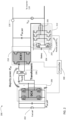
- FIG. 2 is a schematic diagram of a DC power system 200 in an example embodiment.
- the DC power system 200 may be referred to as a hybrid power system as it includes two types of power sources.
- a primary power source 202 provides a majority of the power for the transport refrigeration system 100.
- the primary power source 202 incudes a fuel cell.
- the primary power source 202 includes a battery.
- a secondary power source 204 augments the primary power source 202 when needed.
- the secondary power source 204 includes a battery.
- the output of the primary power source 202 may be a relatively low voltage, for example, 48 volts DC.
- the transport refrigeration system 100 may require a higher voltage, for example, 750 volts DC.
- the output of the primary power source 202 is connected to a DC-AC converter 206.
- the DC-AC converter 206 uses switches (e.g., silicon carbide (SiC) metal-oxide-semiconductor field-effect transistors (MOSFETs)) to produce an AC output.
- a controller 300 controls the switches in the DC-AC converter 206.
- the controller 300 may be implemented using a general-purpose microprocessor executing a computer program stored on a storage medium to perform the operations described herein. Alternatively, the controller 300 may be implemented in hardware (e.g., application-specific integrated circuit (ASIC), field-programmable gate array (FPGA)) or in a combination of hardware/software.
- ASIC application-specific integrated circuit
- FPGA field-programmable gate array
- the output of the DC-AC converter 206 is supplied to a transformer 208.
- the transformer 208 may be a high frequency, LLC transformer.
- the transformer 208 increases the AC output of the DC-AC converter 206 by a step up value (e.g., 15x).
- the stepped-up output of the transformer 208 is provided to an AC-DC converter 210.
- the AC-DC converter 210 uses switches (e.g., gallium nitride (GaN) MOSFETs) to produce a primary DC voltage.
- the controller 300 controls the switches in the AC-DC converter 210.
- the DC-AC converter 206, transformer 208 and AC-DC converter 210 provide an inductance, capacitance (LLC) converter (or dual active bridge) using a zero voltage switching (ZVS) mode to minimize switching losses, which results in increased efficiency, a smaller cooling system and overall smaller system.
- LLC inductance, capacitance
- ZVS zero voltage switching
- the secondary power source 204 is connected to the output of the AC-DC converter 210 though a DC-DC converter 212.
- the DC-DC converter 212 may be, for example, a buck converter.
- the DC-DC converter 212 uses switches (e.g., GaN MOSFETs) to produce a secondary DC voltage.
- the controller 300 controls the switches in the DC-DC converter 212.
- the secondary power source 204 and the DC-DC converter 212 are connected in electrical series with the output of AC-DC converter 210.
- the secondary power source 204 implements hard switching at the cost of higher switching losses to fine tune the secondary DC voltage and provide higher precision at the output voltage level.
- the voltage handled by the DC-DC converter 212 is low voltage (hence reducing switching losses) and GaN devices may be used for lower switching losses.
- the secondary power source 204 may utilize GaN switches to switch at higher frequency and interleaving branches of three inductors 205 to minimize inductor size, which provides higher power density.
- the DC-DC converter 212 utilizes the auxiliary leg 207 (two switches in series between the positive terminal of the battery 204 and the negative terminal of the battery 204) to change the polarity of the secondary DC voltage to be additive or subtractive to the primary DC voltage.
- the controller 300 monitors the primary DC voltage output by AC-DC converter 210 through a sensor 220. If the primary DC voltage is less than a reference (e.g., 750 volts DC), the controller 300 controls the DC-DC converter 212 to supply a positive secondary DC voltage, which is combined with the primary DC voltage.
- the controller 30 modifies a switching pattern of the DC-DC converter 212 to achieve the necessary remaining voltage needed for the final total Vdc output voltage of the DC/DC converter 200. If needed (due to high load demand by the refrigeration unit), the controller may command the DC-DC converter 212 to change the polarity of the secondary DC voltage (through auxiliary leg 207) to reduce extreme points in the primary DC voltage.
- the controller 300 controls the DC-DC converter 212 to supply a negative secondary DC voltage (through auxiliary leg 207), which is combined with the primary DC voltage.
- the combination of the primary DC voltage and the secondary DC voltage is the output of the DC power system 200.
- the secondary power source 204 accounts for transients in the primary DC voltage to provide a stable DC output from the DC power system 200.
- the primary power source 202 e.g., a battery or fuel cell
- the secondary power source 204 e.g., battery, capacitor, etc.
- the controller 300 operates the AC-DC converter 206 and AC-DC converter 210 to favor charging the battery 204 when the DC output voltage demand by the refrigeration system is relaxed, such as maintaining temperature as opposed to a "pull down" condition where the power requirement is high.
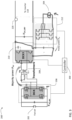
- FIG. 3 is a schematic diagram of a DC power system 200' in an example embodiment.
- the elements of FIG. 3 are similar to those in FIG. 2 .
- the notable difference in FIG. 3 is that the secondary power source 204 and the DC-DC converter 212 are connected in electrical parallel with the output of AC-DC converter 210.
- the DC power system 200' operates in a similar manner as DC power system 200 of FIG. 2 , in that the secondary power source 204 is used to increase or decrease the primary DC voltage output by AC-DC converter 210.
- Embodiments of this invention enable cost optimization of a transport refrigeration system by allowing a secondary power source 204 to account for transients in a primary power source 202.
- the DC-AC converter 206, transformer 208 and AC-DC converter 210 are designed to reduce losses and ensure efficiency.
- the secondary power source 204 and DC-DC converter 212 may be less efficient, but ensure that the DC power system satisfies the voltage requirement for the inverter 110.
- the DC-AC converter 206, AC-DC converter 210 and DC-DC converter 212 may use different types of switches.
- the DC-AC converter 206 may use SiC switches for handling high voltage and ZVS (soft switching).
- the AC-DC converter 210 may use GaN switches and the DC-DC converter 212 may use SiC switches.
Landscapes
- Engineering & Computer Science (AREA)
- Power Engineering (AREA)
- Mechanical Engineering (AREA)
- Physics & Mathematics (AREA)
- Thermal Sciences (AREA)
- General Engineering & Computer Science (AREA)
- Transportation (AREA)
- Life Sciences & Earth Sciences (AREA)
- Sustainable Development (AREA)
- Sustainable Energy (AREA)
- Dc-Dc Converters (AREA)
- Fuel Cell (AREA)
Abstract
Description
- The present invention relates to the art of transport refrigeration systems, and more specifically, to hybrid power systems for transport refrigeration systems.
- Transport refrigeration systems may use multiple power sources, such as AC main power, fuel powered generators, batteries, etc. While existing power systems are well suited for their intended purposes, improvements in efficiency and/or size would be beneficial.
- According to a first aspect, a transport refrigeration system includes a compressor, condenser and evaporator; an inverter providing a multiphase, AC output voltage to the compressor; and a DC power system having an output coupled to the inverter, the DC power system including: a primary power source; a DC-AC converter connected to the primary power source; a transformer connected to the DC-AC converter; an AC-DC converter connected to the transformer, the AC-DC converter outputting a primary DC voltage; a secondary power source; and a DC-DC converter connected to the secondary power source, the DC-DC converter outputting a secondary DC voltage; wherein a combination of the primary DC voltage and the secondary DC voltage provides the output of the DC power system.
- Optionally, the primary power source may include a fuel cell.
- Optionally, the primary power source may include a battery.
- Optionally, the secondary power source may include a battery.
- Optionally, the DC-DC converter may be connected in electrical series with the AC-DC converter.
- Optionally, the DC-DC converter may be connected in electrical parallel with the AC-DC converter.
- Optionally, a controller may be coupled to the DC-DC converter.
- Optionally, a sensor may be in communication with the controller, the sensor configured to detect the primary DC voltage.
- Optionally, the controller may be configured to compare the primary DC voltage to a reference.
- Optionally, the controller may be configured to make the secondary DC voltage positive when the primary DC voltage is less than the reference.
- Optionally, the controller may be configured to make the secondary DC voltage negative when the primary DC voltage is greater than the reference.
- Optionally, the DC-AC converter may include SiC switches, the AC-DC converter may include GaN switches and the DC-DC converter may include GaN switches.
- Optionally, the DC-AC converter may include SiC switches, the AC-DC converter may include GaN switches and the DC-DC converter may include SiC switches.
- Optionally, the transformer may be a high switching frequency transformer with zero voltage switching.
- According to a second aspect, a transport refrigeration system includes a compressor, condenser and evaporator; an inverter providing a multiphase, AC output voltage to the compressor; and a DC power system having an output coupled to the inverter, the DC power system including: a primary power source; a DC-AC converter connected to the primary power source; a transformer connected to the DC-AC converter; an AC-DC converter connected to the transformer, the AC-DC converter outputting a primary DC voltage; a secondary power source; and a DC-DC converter connected to the secondary power source, the DC-DC converter outputting a secondary DC voltage; wherein a combination of the primary DC voltage and the secondary DC voltage provides the output of the DC power system; wherein the primary power source includes a fuel cell; wherein the DC-DC converter is connected in electrical series with the AC-DC converter.
- Optionally a controller may be coupled to the DC-DC converter; wherein the controller is configured to make the secondary DC voltage positive when the primary DC voltage is less than a reference.
- Optionally, the controller may be configured to make the secondary DC voltage negative when the primary DC voltage is greater than the reference.
- According to a third aspect, a transport refrigeration system includes a compressor, condenser and evaporator; an inverter providing a multiphase, AC output voltage to the compressor; and a DC power system having an output coupled to the inverter, the DC power system including: a primary power source; a DC-AC converter connected to the primary power source; a transformer connected to the DC-AC converter; an AC-DC converter connected to the transformer, the AC-DC converter outputting a primary DC voltage; a secondary power source; and a DC-DC converter connected to the secondary power source, the DC-DC converter outputting a secondary DC voltage; wherein a combination of the primary DC voltage and the secondary DC voltage provides the output of the DC power system; wherein the primary power source includes a fuel cell; wherein the DC-DC converter is connected in electrical parallel with the AC-DC converter.
- Optionally a controller may be coupled to the DC-DC converter; wherein the controller is configured to make the secondary DC voltage positive when the primary DC voltage is less than a reference.
- Optionally, the controller may be configured to make the secondary DC voltage negative when the primary DC voltage is greater than the reference.
- Additional technical features and benefits are realized through the techniques of the present invention. Embodiments and aspects of the invention are described in detail herein and are considered a part of the claimed subject matter. For a better understanding, refer to the detailed description and to the drawings.
- The following descriptions should not be considered limiting in any way. With reference to the accompanying drawings, like elements are numbered alike:
-
FIG. 1 is a block diagram of a transport refrigeration system; -
FIG. 2 is a schematic diagram of a DC power system; -
FIG. 3 is a schematic diagram of a DC power system. - A detailed description of one or more exemplary embodiments of the disclosed apparatus and method are presented herein by way of exemplification and not limitation with reference to the Figures.
-
FIG. 1 is a block diagram of atransport refrigeration system 100. Thetransport refrigeration system 100 may be configured to condition air in acargo space 20, which may include a refrigerated container, a refrigerated trailer, etc. - The
transport refrigeration system 100 includes avariable speed motor 102 that is coupled to acompressor 104. Thecompressor 104 includes an impeller/rotor that rotates and compresses liquid refrigerant to a superheated refrigerant vapor for delivery to a condenser 106. In the condenser 106, the refrigerant vapor is liquefied at high pressure and rejects heat (e.g., to the outside air via a condenser fan in an air-cooled application). The liquid refrigerant exiting the condenser 106 is delivered to anevaporator 108 through anexpansion valve 107. The refrigerant passes through theexpansion valve 107 where a pressure drop causes the high-pressure liquid refrigerant to achieve a lower pressure combination of liquid and vapor. As fluid passes theevaporator 108, the low-pressure liquid refrigerant evaporates, absorbing heat from the fluid, thereby cooling the fluid and evaporating the refrigerant. The low-pressure refrigerant is again delivered to thecompressor 104 where it is compressed to a high-pressure, high temperature gas, and delivered to the condenser 106 to start the refrigeration cycle again. It is to be appreciated that while a specific transport refrigeration system is shown inFIG. 1 , the present teachings are applicable to any transport refrigeration system. - As shown in
FIG. 1 , thecompressor 104 is driven by avariable speed motor 102 from power supplied from a direct current (DC)power system 200 and a DC-alternating current (AC)inverter 110. Theinverter 110 includes solid-state electronics to produce multiphase, AC output voltage. In an embodiment, theinverter 110 converts the DC voltage from theDC power system 200 into a multiphase, AC output voltage, at a desired frequency and/or magnitude in order to drive themultiphase motor 102.Such inverters 110 are known in the art. -
FIG. 2 is a schematic diagram of aDC power system 200 in an example embodiment. The DCpower system 200 may be referred to as a hybrid power system as it includes two types of power sources. Aprimary power source 202 provides a majority of the power for thetransport refrigeration system 100. In the example embodiment ofFIG. 2 , theprimary power source 202 incudes a fuel cell. In other embodiments, theprimary power source 202 includes a battery. Asecondary power source 204 augments theprimary power source 202 when needed. In the example embodiment ofFIG. 2 , thesecondary power source 204 includes a battery. - The output of the
primary power source 202 may be a relatively low voltage, for example, 48 volts DC. Thetransport refrigeration system 100 may require a higher voltage, for example, 750 volts DC. The output of theprimary power source 202 is connected to a DC-AC converter 206. The DC-AC converter 206 uses switches (e.g., silicon carbide (SiC) metal-oxide-semiconductor field-effect transistors (MOSFETs)) to produce an AC output. Acontroller 300 controls the switches in the DC-AC converter 206. Thecontroller 300 may be implemented using a general-purpose microprocessor executing a computer program stored on a storage medium to perform the operations described herein. Alternatively, thecontroller 300 may be implemented in hardware (e.g., application-specific integrated circuit (ASIC), field-programmable gate array (FPGA)) or in a combination of hardware/software. - The output of the DC-
AC converter 206 is supplied to atransformer 208. Thetransformer 208 may be a high frequency, LLC transformer. Thetransformer 208 increases the AC output of the DC-AC converter 206 by a step up value (e.g., 15x). The stepped-up output of thetransformer 208 is provided to an AC-DC converter 210. The AC-DC converter 210 uses switches (e.g., gallium nitride (GaN) MOSFETs) to produce a primary DC voltage. Thecontroller 300 controls the switches in the AC-DC converter 210. The DC-AC converter 206,transformer 208 and AC-DC converter 210 provide an inductance, capacitance (LLC) converter (or dual active bridge) using a zero voltage switching (ZVS) mode to minimize switching losses, which results in increased efficiency, a smaller cooling system and overall smaller system. - The
secondary power source 204 is connected to the output of the AC-DC converter 210 though a DC-DC converter 212. The DC-DC converter 212 may be, for example, a buck converter. The DC-DC converter 212 uses switches (e.g., GaN MOSFETs) to produce a secondary DC voltage. Thecontroller 300 controls the switches in the DC-DC converter 212. Thesecondary power source 204 and the DC-DC converter 212 are connected in electrical series with the output of AC-DC converter 210. Thesecondary power source 204 implements hard switching at the cost of higher switching losses to fine tune the secondary DC voltage and provide higher precision at the output voltage level. However, the voltage handled by the DC-DC converter 212 is low voltage (hence reducing switching losses) and GaN devices may be used for lower switching losses. - The
secondary power source 204 may utilize GaN switches to switch at higher frequency and interleaving branches of threeinductors 205 to minimize inductor size, which provides higher power density. The DC-DC converter 212 utilizes the auxiliary leg 207 (two switches in series between the positive terminal of thebattery 204 and the negative terminal of the battery 204) to change the polarity of the secondary DC voltage to be additive or subtractive to the primary DC voltage. - In operation, the
controller 300 monitors the primary DC voltage output by AC-DC converter 210 through asensor 220. If the primary DC voltage is less than a reference (e.g., 750 volts DC), thecontroller 300 controls the DC-DC converter 212 to supply a positive secondary DC voltage, which is combined with the primary DC voltage. The controller 30 modifies a switching pattern of the DC-DC converter 212 to achieve the necessary remaining voltage needed for the final total Vdc output voltage of the DC/DC converter 200. If needed (due to high load demand by the refrigeration unit), the controller may command the DC-DC converter 212 to change the polarity of the secondary DC voltage (through auxiliary leg 207) to reduce extreme points in the primary DC voltage. - If the primary DC voltage is greater than the reference, the
controller 300 controls the DC-DC converter 212 to supply a negative secondary DC voltage (through auxiliary leg 207), which is combined with the primary DC voltage. The combination of the primary DC voltage and the secondary DC voltage is the output of theDC power system 200. In this way, thesecondary power source 204 accounts for transients in the primary DC voltage to provide a stable DC output from theDC power system 200. - During time periods where there is low or no demand for power from the
DC power system 200, the primary power source 202 (e.g., a battery or fuel cell) may be used to charge the secondary power source 204 (e.g., battery, capacitor, etc.). Thecontroller 300 operates the AC-DC converter 206 and AC-DC converter 210 to favor charging thebattery 204 when the DC output voltage demand by the refrigeration system is relaxed, such as maintaining temperature as opposed to a "pull down" condition where the power requirement is high. -
FIG. 3 is a schematic diagram of a DC power system 200' in an example embodiment. The elements ofFIG. 3 are similar to those inFIG. 2 . The notable difference inFIG. 3 , is that thesecondary power source 204 and the DC-DC converter 212 are connected in electrical parallel with the output of AC-DC converter 210. The DC power system 200' operates in a similar manner asDC power system 200 ofFIG. 2 , in that thesecondary power source 204 is used to increase or decrease the primary DC voltage output by AC-DC converter 210. - Embodiments of this invention enable cost optimization of a transport refrigeration system by allowing a
secondary power source 204 to account for transients in aprimary power source 202. The DC-AC converter 206,transformer 208 and AC-DC converter 210 are designed to reduce losses and ensure efficiency. Thesecondary power source 204 and DC-DC converter 212 may be less efficient, but ensure that the DC power system satisfies the voltage requirement for theinverter 110. - The DC-
AC converter 206, AC-DC converter 210 and DC-DC converter 212 may use different types of switches. For example, the DC-AC converter 206 may use SiC switches for handling high voltage and ZVS (soft switching). The AC-DC converter 210 may use GaN switches and the DC-DC converter 212 may use SiC switches. - The terminology used herein is for the purpose of describing particular embodiments only and is not intended to be limiting of the present invention. As used herein, the singular forms "a", "an" and "the" are intended to include the plural forms as well, unless the context clearly indicates otherwise. It will be further understood that the terms "comprises" and/or "comprising," when used in this specification, specify the presence of stated features, integers, steps, operations, elements, and/or components, but do not preclude the presence or addition of one or more other features, integers, steps, operations, element components, and/or groups thereof.
- While the present invention has been described with reference to an exemplary embodiment or embodiments, it will be understood by those skilled in the art that various changes may be made and equivalents may be substituted for elements thereof without departing from the scope of the present invention as defined by the claims. In addition, many modifications may be made to adapt a particular situation or material to the teachings of the present invention without departing from the scope of the claims. Therefore, it is intended that the present invention not be limited to the particular embodiment disclosed as the best mode contemplated for carrying out this present invention, but that the present invention will include all embodiments falling within the scope of the claims.
Claims (15)
- A transport refrigeration system (100) comprising:a compressor (104), condenser (106) and evaporator (108);an inverter (110) providing a multiphase, AC output voltage to the compressor; anda DC power system (200; 200') having an output coupled to the inverter, the DC power system including:a primary power source (202);a DC-AC converter (206) connected to the primary power source;a transformer (208) connected to the DC-AC converter;an AC-DC converter (210) connected to the transformer, the AC-DC converter outputting a primary DC voltage;a secondary power source (204); anda DC-DC converter (212) connected to the secondary power source, the DC-DC converter outputting a secondary DC voltage;wherein a combination of the primary DC voltage and the secondary DC voltage provides the output of the DC power system (200; 200').
- The transport refrigeration system of claim 1, wherein the primary power source (202) includes a fuel cell; or
wherein the primary power source (202) includes a battery. - The transport refrigeration system of claim 1 or 2, wherein the secondary power source (204) includes a battery.
- The transport refrigeration system of any preceding claim, wherein the DC-DC converter (212) is connected in electrical series with the AC-DC converter (210); or
wherein the DC-DC converter (212) is connected in electrical parallel with the AC-DC converter (210). - The transport refrigeration system of any preceding claim, further comprising a controller (300) coupled to the DC-DC converter (212).
- The transport refrigeration system of claim 5, further comprising a sensor (220) in communication with the controller (300), the sensor configured to detect the primary DC voltage.
- The transport refrigeration system of claim 5 or 6, wherein the controller (300) is configured to compare the primary DC voltage to a reference.
- The transport refrigeration system of claim 7, wherein the controller (300) is configured to make the secondary DC voltage positive when the primary DC voltage is less than the reference; and/or
wherein the controller (300) is configured to make the secondary DC voltage negative when the primary DC voltage is greater than the reference. - The transport refrigeration system of any preceding claim, wherein the DC-AC converter (206) includes SiC switches, the AC-DC converter (210) includes GaN switches, and the DC-DC converter (212) includes GaN switches.
- The transport refrigeration system of any of claims 1-8, wherein the DC-AC converter (206) includes SiC switches, the AC-DC converter (210) includes GaN switches, and the DC-DC converter (212) includes SiC switches.
- The transport refrigeration system of any preceding claim, wherein the transformer (208) is a high switching frequency transformer with zero voltage switching.
- A transport refrigeration system (100) comprising:a compressor (104), condenser (106) and evaporator (108);an inverter (110) providing a multiphase, AC output voltage to the compressor; anda DC power system (200) having an output coupled to the inverter, the DC power system including:a primary power source (202);a DC-AC converter (206) connected to the primary power source;a transformer (208) connected to the DC-AC converter;an AC-DC converter (210) connected to the transformer, the AC-DC converter outputting a primary DC voltage;a secondary power source (204); anda DC-DC converter (212) connected to the secondary power source, the DC-DC converter outputting a secondary DC voltage;wherein a combination of the primary DC voltage and the secondary DC voltage provides the output of the DC power system (200);wherein the primary power source (202) includes a fuel cell; andwherein the DC-DC converter (212) is connected in electrical series with the AC-DC converter (210).
- The transport refrigeration system of claim 12, further comprising a controller (300) coupled to the DC-DC converter (212);wherein the controller is configured to make the secondary DC voltage positive when the primary DC voltage is less than a reference; and/orwherein the controller (300) is configured to make the secondary DC voltage negative when the primary DC voltage is greater than the reference.
- A transport refrigeration system (100) comprising:a compressor (104), condenser (106) and evaporator (108);an inverter (110) providing a multiphase, AC output voltage to the compressor; anda DC power system (200') having an output coupled to the inverter, the DC power system including:a primary power source (202);a DC-AC converter (206) connected to the primary power source;a transformer (208) connected to the DC-AC converter;an AC-DC converter (210) connected to the transformer, the AC-DC converter outputting a primary DC voltage;a secondary power source (204); anda DC-DC converter (212) connected to the secondary power source, the DC-DC converter outputting a secondary DC voltage;wherein a combination of the primary DC voltage and the secondary DC voltage provides the output of the DC power system (200');wherein the primary power source (202) includes a fuel cell; andwherein the DC-DC converter (212) is connected in electrical parallel with the AC-DC converter (210).
- The transport refrigeration system of claim 14, further comprising a controller (300) coupled to the DC-DC converter (212);wherein the controller is configured to make the secondary DC voltage positive when the primary DC voltage is less than a reference; and/orwherein the controller (300) is configured to make the secondary DC voltage negative when the primary DC voltage is greater than the reference.
Applications Claiming Priority (1)
| Application Number | Priority Date | Filing Date | Title |
|---|---|---|---|
| US202263390028P | 2022-07-18 | 2022-07-18 |
Publications (2)
| Publication Number | Publication Date |
|---|---|
| EP4310417A2 true EP4310417A2 (en) | 2024-01-24 |
| EP4310417A3 EP4310417A3 (en) | 2024-03-20 |
Family
ID=87377908
Family Applications (1)
| Application Number | Title | Priority Date | Filing Date |
|---|---|---|---|
| EP23185943.0A Pending EP4310417A3 (en) | 2022-07-18 | 2023-07-17 | Hybrid power system for transport refrigeration systems |
Country Status (3)
| Country | Link |
|---|---|
| US (1) | US12355339B2 (en) |
| EP (1) | EP4310417A3 (en) |
| CN (1) | CN117416186A (en) |
Citations (2)
| Publication number | Priority date | Publication date | Assignee | Title |
|---|---|---|---|---|
| US20090302818A1 (en) * | 2006-06-01 | 2009-12-10 | Toyota Jidosha Kabushiki Kaisha | Power Supply Device and Control Method of the Same |
| US20110084645A1 (en) * | 2009-10-13 | 2011-04-14 | Samsung Electronics Co., Ltd. | Power supply device and driving method thereof |
Family Cites Families (15)
| Publication number | Priority date | Publication date | Assignee | Title |
|---|---|---|---|---|
| US4979967A (en) | 1989-05-04 | 1990-12-25 | Microclean Environmental Transport Services, Ltd. | Contaminant transport apparatus |
| US5761908A (en) | 1994-06-10 | 1998-06-09 | Air Quality Engineering | Apparatus suited for ventilating rooms contaminated with infectious disease organisms |
| KR100199506B1 (en) * | 1996-10-29 | 1999-06-15 | 윤문수 | A zero voltage/current switching circuit for reduced ripple current of the full-bridge dc/dc converter |
| WO2016004399A1 (en) | 2014-07-02 | 2016-01-07 | Free Air, Inc. | Room air cleaner systems and methods related thereto |
| JP6177734B2 (en) | 2014-07-22 | 2017-08-09 | ダイキン工業株式会社 | Air cleaner |
| KR102473895B1 (en) | 2015-05-14 | 2022-12-07 | 코웨이 주식회사 | Dehumidification apparatus |
| WO2016203787A1 (en) | 2015-06-18 | 2016-12-22 | シャープ株式会社 | Air blowing device |
| KR20190018181A (en) | 2017-08-14 | 2019-02-22 | 상상한자리 주식회사 | Portable air cleaner |
| EP3626489A1 (en) | 2018-09-19 | 2020-03-25 | Thermo King Corporation | Methods and systems for energy management of a transport climate control system |
| US11932076B2 (en) | 2018-09-28 | 2024-03-19 | Carrier Corporation | Transportation refrigeration unit with external AC generator power source |
| CN112334341B (en) | 2018-09-28 | 2025-02-28 | 开利公司 | Electrical architecture for powering transport refrigeration units |
| US10926610B2 (en) | 2018-10-31 | 2021-02-23 | Thermo King Corporation | Methods and systems for controlling a mild hybrid system that powers a transport climate control system |
| US11554638B2 (en) | 2018-12-28 | 2023-01-17 | Thermo King Llc | Methods and systems for preserving autonomous operation of a transport climate control system |
| US11794551B2 (en) * | 2019-09-09 | 2023-10-24 | Thermo King Llc | Optimized power distribution to transport climate control systems amongst one or more electric supply equipment stations |
| US11254223B2 (en) * | 2019-11-06 | 2022-02-22 | GM Global Technology Operations LLC | Operating mode optimization for electric propulsion system with downsized DC-DC converter |
-
2023
- 2023-07-06 US US18/347,976 patent/US12355339B2/en active Active
- 2023-07-17 EP EP23185943.0A patent/EP4310417A3/en active Pending
- 2023-07-17 CN CN202310871849.5A patent/CN117416186A/en active Pending
Patent Citations (2)
| Publication number | Priority date | Publication date | Assignee | Title |
|---|---|---|---|---|
| US20090302818A1 (en) * | 2006-06-01 | 2009-12-10 | Toyota Jidosha Kabushiki Kaisha | Power Supply Device and Control Method of the Same |
| US20110084645A1 (en) * | 2009-10-13 | 2011-04-14 | Samsung Electronics Co., Ltd. | Power supply device and driving method thereof |
Also Published As
| Publication number | Publication date |
|---|---|
| EP4310417A3 (en) | 2024-03-20 |
| US12355339B2 (en) | 2025-07-08 |
| CN117416186A (en) | 2024-01-19 |
| US20240022160A1 (en) | 2024-01-18 |
Similar Documents
| Publication | Publication Date | Title |
|---|---|---|
| CN103125066B (en) | Power conversion equipment and refrigeration and air conditioning equipment | |
| JP6071300B2 (en) | Transport refrigeration system | |
| US20190074789A1 (en) | Dc to dc converter sourcing variable dc link voltage | |
| US11424640B2 (en) | Integrated high-voltage-low-voltage DC-DC converter and charger with active filter | |
| US20160181925A1 (en) | Bidirectional dc-dc converter | |
| US8514601B2 (en) | Power conversion with added pseudo-phase | |
| US8278778B2 (en) | HVAC/R battery back-up power supply system having a variable frequency drive (VFD) power supply | |
| US8193660B2 (en) | HVAC/R system having power back-up system with a DC-DC converter | |
| US9800077B2 (en) | DC power-supply device and refrigeration-cycle application device including the same | |
| He et al. | Design of 1 kW bidirectional half-bridge CLLC converter for electric vehicle charging systems | |
| CN104539184A (en) | Efficient transport refrigeration machine | |
| JP4957350B2 (en) | Power conversion device and inverter control device for motor drive using the same | |
| CN101932836A (en) | Apparatus and method for controlling the operation of a compressor | |
| US20050189904A1 (en) | System and method for increasing output horsepower and efficiency in a motor | |
| US12355339B2 (en) | Hybrid power system for transport refrigeration systems | |
| US20180358906A1 (en) | Direct-current power supply device and refrigeration cycle-applied apparatus | |
| EP4138289A1 (en) | Dual mode converter for air conditioning system | |
| KR102204470B1 (en) | A hybrid cooling system using of electric and hydraulic motors | |
| KR101796741B1 (en) | DC-DC converter for vehicle and air conditioner system for vehicle having the same | |
| EP3905468B1 (en) | Three-phase generator with adaptive taps for use in a transport climate control system | |
| CN104501487A (en) | High-reliability transportation refrigerator | |
| CN212992208U (en) | Interleaved LLC resonant converter for vehicle-mounted PEV battery charger | |
| KR101850196B1 (en) | Power conversion device, and cooling air conditioning device | |
| KR20180042830A (en) | A cooling system using of hydraulic transmission | |
| US20250158535A1 (en) | Dc bus capacitor assemblies for vienna vfd in air conditioning systems |
Legal Events
| Date | Code | Title | Description |
|---|---|---|---|
| PUAI | Public reference made under article 153(3) epc to a published international application that has entered the european phase |
Free format text: ORIGINAL CODE: 0009012 |
|
| STAA | Information on the status of an ep patent application or granted ep patent |
Free format text: STATUS: THE APPLICATION HAS BEEN PUBLISHED |
|
| AK | Designated contracting states |
Kind code of ref document: A2 Designated state(s): AL AT BE BG CH CY CZ DE DK EE ES FI FR GB GR HR HU IE IS IT LI LT LU LV MC ME MK MT NL NO PL PT RO RS SE SI SK SM TR |
|
| PUAL | Search report despatched |
Free format text: ORIGINAL CODE: 0009013 |
|
| AK | Designated contracting states |
Kind code of ref document: A3 Designated state(s): AL AT BE BG CH CY CZ DE DK EE ES FI FR GB GR HR HU IE IS IT LI LT LU LV MC ME MK MT NL NO PL PT RO RS SE SI SK SM TR |
|
| RIC1 | Information provided on ipc code assigned before grant |
Ipc: H02M 7/00 20060101ALN20240212BHEP Ipc: F25B 49/02 20060101ALI20240212BHEP Ipc: F25B 27/00 20060101AFI20240212BHEP |
|
| STAA | Information on the status of an ep patent application or granted ep patent |
Free format text: STATUS: REQUEST FOR EXAMINATION WAS MADE |
|
| 17P | Request for examination filed |
Effective date: 20240919 |
|
| RBV | Designated contracting states (corrected) |
Designated state(s): AL AT BE BG CH CY CZ DE DK EE ES FI FR GB GR HR HU IE IS IT LI LT LU LV MC ME MK MT NL NO PL PT RO RS SE SI SK SM TR |
|
| STAA | Information on the status of an ep patent application or granted ep patent |
Free format text: STATUS: EXAMINATION IS IN PROGRESS |
|
| 17Q | First examination report despatched |
Effective date: 20260219 |