EP4310317B1 - Variable speed reconfigurable pump/turbine clusters - Google Patents
Variable speed reconfigurable pump/turbine clusters Download PDFInfo
- Publication number
- EP4310317B1 EP4310317B1 EP23184819.3A EP23184819A EP4310317B1 EP 4310317 B1 EP4310317 B1 EP 4310317B1 EP 23184819 A EP23184819 A EP 23184819A EP 4310317 B1 EP4310317 B1 EP 4310317B1
- Authority
- EP
- European Patent Office
- Prior art keywords
- hrms
- hrm
- controller
- cluster
- flow path
- Prior art date
- Legal status (The legal status is an assumption and is not a legal conclusion. Google has not performed a legal analysis and makes no representation as to the accuracy of the status listed.)
- Active
Links
Images



Classifications
-
- F—MECHANICAL ENGINEERING; LIGHTING; HEATING; WEAPONS; BLASTING
- F03—MACHINES OR ENGINES FOR LIQUIDS; WIND, SPRING, OR WEIGHT MOTORS; PRODUCING MECHANICAL POWER OR A REACTIVE PROPULSIVE THRUST, NOT OTHERWISE PROVIDED FOR
- F03B—MACHINES OR ENGINES FOR LIQUIDS
- F03B13/00—Adaptations of machines or engines for special use; Combinations of machines or engines with driving or driven apparatus; Power stations or aggregates
- F03B13/06—Stations or aggregates of water-storage type, e.g. comprising a turbine and a pump
-
- F—MECHANICAL ENGINEERING; LIGHTING; HEATING; WEAPONS; BLASTING
- F04—POSITIVE - DISPLACEMENT MACHINES FOR LIQUIDS; PUMPS FOR LIQUIDS OR ELASTIC FLUIDS
- F04D—NON-POSITIVE-DISPLACEMENT PUMPS
- F04D27/00—Control, e.g. regulation, of pumps, pumping installations or pumping systems specially adapted for elastic fluids
- F04D27/001—Testing thereof; Determination or simulation of flow characteristics; Stall or surge detection, e.g. condition monitoring
-
- F—MECHANICAL ENGINEERING; LIGHTING; HEATING; WEAPONS; BLASTING
- F16—ENGINEERING ELEMENTS AND UNITS; GENERAL MEASURES FOR PRODUCING AND MAINTAINING EFFECTIVE FUNCTIONING OF MACHINES OR INSTALLATIONS; THERMAL INSULATION IN GENERAL
- F16H—GEARING
- F16H41/00—Rotary fluid gearing of the hydrokinetic type
- F16H41/04—Combined pump-turbine units
- F16H41/22—Gearing systems consisting of a plurality of hydrokinetic units operating alternatively, e.g. made effective or ineffective by filling or emptying or by mechanical clutches
-
- F—MECHANICAL ENGINEERING; LIGHTING; HEATING; WEAPONS; BLASTING
- F03—MACHINES OR ENGINES FOR LIQUIDS; WIND, SPRING, OR WEIGHT MOTORS; PRODUCING MECHANICAL POWER OR A REACTIVE PROPULSIVE THRUST, NOT OTHERWISE PROVIDED FOR
- F03B—MACHINES OR ENGINES FOR LIQUIDS
- F03B15/00—Controlling
-
- F—MECHANICAL ENGINEERING; LIGHTING; HEATING; WEAPONS; BLASTING
- F03—MACHINES OR ENGINES FOR LIQUIDS; WIND, SPRING, OR WEIGHT MOTORS; PRODUCING MECHANICAL POWER OR A REACTIVE PROPULSIVE THRUST, NOT OTHERWISE PROVIDED FOR
- F03B—MACHINES OR ENGINES FOR LIQUIDS
- F03B15/00—Controlling
- F03B15/02—Controlling by varying liquid flow
- F03B15/04—Controlling by varying liquid flow of turbines
- F03B15/06—Regulating, i.e. acting automatically
- F03B15/08—Regulating, i.e. acting automatically by speed, e.g. by measuring electric frequency or liquid flow
-
- F—MECHANICAL ENGINEERING; LIGHTING; HEATING; WEAPONS; BLASTING
- F03—MACHINES OR ENGINES FOR LIQUIDS; WIND, SPRING, OR WEIGHT MOTORS; PRODUCING MECHANICAL POWER OR A REACTIVE PROPULSIVE THRUST, NOT OTHERWISE PROVIDED FOR
- F03B—MACHINES OR ENGINES FOR LIQUIDS
- F03B15/00—Controlling
- F03B15/02—Controlling by varying liquid flow
- F03B15/04—Controlling by varying liquid flow of turbines
- F03B15/06—Regulating, i.e. acting automatically
- F03B15/18—Regulating, i.e. acting automatically for safety purposes, e.g. preventing overspeed
-
- F—MECHANICAL ENGINEERING; LIGHTING; HEATING; WEAPONS; BLASTING
- F04—POSITIVE - DISPLACEMENT MACHINES FOR LIQUIDS; PUMPS FOR LIQUIDS OR ELASTIC FLUIDS
- F04D—NON-POSITIVE-DISPLACEMENT PUMPS
- F04D25/00—Pumping installations or systems
- F04D25/16—Combinations of two or more pumps ; Producing two or more separate gas flows
-
- F—MECHANICAL ENGINEERING; LIGHTING; HEATING; WEAPONS; BLASTING
- F04—POSITIVE - DISPLACEMENT MACHINES FOR LIQUIDS; PUMPS FOR LIQUIDS OR ELASTIC FLUIDS
- F04D—NON-POSITIVE-DISPLACEMENT PUMPS
- F04D27/00—Control, e.g. regulation, of pumps, pumping installations or pumping systems specially adapted for elastic fluids
- F04D27/004—Control, e.g. regulation, of pumps, pumping installations or pumping systems specially adapted for elastic fluids by varying driving speed
-
- F—MECHANICAL ENGINEERING; LIGHTING; HEATING; WEAPONS; BLASTING
- F16—ENGINEERING ELEMENTS AND UNITS; GENERAL MEASURES FOR PRODUCING AND MAINTAINING EFFECTIVE FUNCTIONING OF MACHINES OR INSTALLATIONS; THERMAL INSULATION IN GENERAL
- F16H—GEARING
- F16H41/00—Rotary fluid gearing of the hydrokinetic type
- F16H41/24—Details
-
- F—MECHANICAL ENGINEERING; LIGHTING; HEATING; WEAPONS; BLASTING
- F16—ENGINEERING ELEMENTS AND UNITS; GENERAL MEASURES FOR PRODUCING AND MAINTAINING EFFECTIVE FUNCTIONING OF MACHINES OR INSTALLATIONS; THERMAL INSULATION IN GENERAL
- F16H—GEARING
- F16H61/00—Control functions within control units of change-speed- or reversing-gearings for conveying rotary motion ; Control of exclusively fluid gearing, friction gearing, gearings with endless flexible members or other particular types of gearing
- F16H61/38—Control of exclusively fluid gearing
- F16H61/48—Control of exclusively fluid gearing hydrodynamic
- F16H61/50—Control of exclusively fluid gearing hydrodynamic controlled by changing the flow, force, or reaction of the liquid in the working circuit, while maintaining a completely filled working circuit
-
- G—PHYSICS
- G05—CONTROLLING; REGULATING
- G05D—SYSTEMS FOR CONTROLLING OR REGULATING NON-ELECTRIC VARIABLES
- G05D13/00—Control of linear speed; Control of angular speed; Control of acceleration or deceleration, e.g. of a prime mover
- G05D13/08—Control of linear speed; Control of angular speed; Control of acceleration or deceleration, e.g. of a prime mover without auxiliary power
- G05D13/10—Centrifugal governors with fly-weights
- G05D13/22—Centrifugal governors with fly-weights counterbalanced by fluid pressure acting upon the articulated riser
-
- F—MECHANICAL ENGINEERING; LIGHTING; HEATING; WEAPONS; BLASTING
- F05—INDEXING SCHEMES RELATING TO ENGINES OR PUMPS IN VARIOUS SUBCLASSES OF CLASSES F01-F04
- F05B—INDEXING SCHEME RELATING TO WIND, SPRING, WEIGHT, INERTIA OR LIKE MOTORS, TO MACHINES OR ENGINES FOR LIQUIDS COVERED BY SUBCLASSES F03B, F03D AND F03G
- F05B2220/00—Application
- F05B2220/20—Application within closed fluid conduits, e.g. pipes
-
- F—MECHANICAL ENGINEERING; LIGHTING; HEATING; WEAPONS; BLASTING
- F05—INDEXING SCHEMES RELATING TO ENGINES OR PUMPS IN VARIOUS SUBCLASSES OF CLASSES F01-F04
- F05B—INDEXING SCHEME RELATING TO WIND, SPRING, WEIGHT, INERTIA OR LIKE MOTORS, TO MACHINES OR ENGINES FOR LIQUIDS COVERED BY SUBCLASSES F03B, F03D AND F03G
- F05B2240/00—Components
- F05B2240/40—Use of a multiplicity of similar components
-
- F—MECHANICAL ENGINEERING; LIGHTING; HEATING; WEAPONS; BLASTING
- F05—INDEXING SCHEMES RELATING TO ENGINES OR PUMPS IN VARIOUS SUBCLASSES OF CLASSES F01-F04
- F05B—INDEXING SCHEME RELATING TO WIND, SPRING, WEIGHT, INERTIA OR LIKE MOTORS, TO MACHINES OR ENGINES FOR LIQUIDS COVERED BY SUBCLASSES F03B, F03D AND F03G
- F05B2260/00—Function
- F05B2260/42—Storage of energy
- F05B2260/422—Storage of energy in the form of potential energy, e.g. pressurized or pumped fluid
-
- F—MECHANICAL ENGINEERING; LIGHTING; HEATING; WEAPONS; BLASTING
- F05—INDEXING SCHEMES RELATING TO ENGINES OR PUMPS IN VARIOUS SUBCLASSES OF CLASSES F01-F04
- F05B—INDEXING SCHEME RELATING TO WIND, SPRING, WEIGHT, INERTIA OR LIKE MOTORS, TO MACHINES OR ENGINES FOR LIQUIDS COVERED BY SUBCLASSES F03B, F03D AND F03G
- F05B2260/00—Function
- F05B2260/80—Diagnostics
-
- F—MECHANICAL ENGINEERING; LIGHTING; HEATING; WEAPONS; BLASTING
- F05—INDEXING SCHEMES RELATING TO ENGINES OR PUMPS IN VARIOUS SUBCLASSES OF CLASSES F01-F04
- F05B—INDEXING SCHEME RELATING TO WIND, SPRING, WEIGHT, INERTIA OR LIKE MOTORS, TO MACHINES OR ENGINES FOR LIQUIDS COVERED BY SUBCLASSES F03B, F03D AND F03G
- F05B2270/00—Control
- F05B2270/10—Purpose of the control system
- F05B2270/101—Purpose of the control system to control rotational speed (n)
-
- F—MECHANICAL ENGINEERING; LIGHTING; HEATING; WEAPONS; BLASTING
- F05—INDEXING SCHEMES RELATING TO ENGINES OR PUMPS IN VARIOUS SUBCLASSES OF CLASSES F01-F04
- F05B—INDEXING SCHEME RELATING TO WIND, SPRING, WEIGHT, INERTIA OR LIKE MOTORS, TO MACHINES OR ENGINES FOR LIQUIDS COVERED BY SUBCLASSES F03B, F03D AND F03G
- F05B2270/00—Control
- F05B2270/10—Purpose of the control system
- F05B2270/20—Purpose of the control system to optimise the performance of a machine
-
- F—MECHANICAL ENGINEERING; LIGHTING; HEATING; WEAPONS; BLASTING
- F05—INDEXING SCHEMES RELATING TO ENGINES OR PUMPS IN VARIOUS SUBCLASSES OF CLASSES F01-F04
- F05B—INDEXING SCHEME RELATING TO WIND, SPRING, WEIGHT, INERTIA OR LIKE MOTORS, TO MACHINES OR ENGINES FOR LIQUIDS COVERED BY SUBCLASSES F03B, F03D AND F03G
- F05B2270/00—Control
- F05B2270/30—Control parameters, e.g. input parameters
- F05B2270/327—Rotor or generator speeds
-
- F—MECHANICAL ENGINEERING; LIGHTING; HEATING; WEAPONS; BLASTING
- F05—INDEXING SCHEMES RELATING TO ENGINES OR PUMPS IN VARIOUS SUBCLASSES OF CLASSES F01-F04
- F05B—INDEXING SCHEME RELATING TO WIND, SPRING, WEIGHT, INERTIA OR LIKE MOTORS, TO MACHINES OR ENGINES FOR LIQUIDS COVERED BY SUBCLASSES F03B, F03D AND F03G
- F05B2270/00—Control
- F05B2270/40—Type of control system
- F05B2270/404—Type of control system active, predictive, or anticipative
-
- F—MECHANICAL ENGINEERING; LIGHTING; HEATING; WEAPONS; BLASTING
- F05—INDEXING SCHEMES RELATING TO ENGINES OR PUMPS IN VARIOUS SUBCLASSES OF CLASSES F01-F04
- F05B—INDEXING SCHEME RELATING TO WIND, SPRING, WEIGHT, INERTIA OR LIKE MOTORS, TO MACHINES OR ENGINES FOR LIQUIDS COVERED BY SUBCLASSES F03B, F03D AND F03G
- F05B2270/00—Control
- F05B2270/50—Control logic embodiment by
- F05B2270/506—Control logic embodiment by hydraulic means, e.g. hydraulic valves within a hydraulic circuit
Definitions
- the invention relates to pumps and turbines, and more particularly, to pumps and turbines that are required to maintain high efficiency over a wide range of conditions of service.
- pumps 102, turbines, and combination pump-turbines are traditionally operated at a fixed rotating speed, which is determined by the driving motor type and/or by the frequency of the power 110 derived from the electrical supply net 100.
- HRM condition of service
- an HRM can have a relatively wide condition of service (“COS") range over which it can be operated, optimal efficiency is typically realized only when the COS is a close match to the "best efficiency point" or BEP of the HRM, which is typically defined in terms of specified ranges of flow rate, flow volume, inlet and outlet pressure, inlet and outlet temperature, and sometimes also gas fraction and solid/liquid fraction, among other conditions.
- COS condition of service
- One approach to maintaining HRM efficiency over wider COS ranges is to implement an HRM that can be driven at variable speeds.
- the BEP of the HRM can be shifted so that it remains close to a varying COS, thereby optimizing the overall efficiency of the process to which the HRM is applied.
- this approach can still be insufficient for some applications that require efficient operation over a very wide COS range.
- HRMs can be used to drive heat pump cycles that store energy by heating or cooling a thermal storage medium.
- a separate pump and turbine can be implemented, or a dual mode pump/turbine HRM can be used to meet the requirements of both the energy storage cycle and the energy recovery cycle of an energy storage system.
- the invention comprises a plurality, or "cluster,” of variable speed HRMs having operating speeds that are independently controlled by an HRM controller.
- the HRMs in the cluster are interconnected with each other by an HRM plumbing system that includes an inlet, an outlet, and one or more valves that can be actuated by the HRM controller to configure a flow path through which a process fluid flows from the inlet to the outlet via one or more of the HRMs in the cluster.
- the following is a very simple example directed to a hypothetical HRM cluster comprising two identical, variable speed pumps, where the HRM cluster is used to store energy resulting from excess capacity of a green energy source by compressing a gas into a storage container.
- the operating speed of each of the pumps can be varied so as to maintain optimal efficiency when the volumetric flow rate through the pump is between 51 and 85 m 3 /h (30 and 50 cubic feet per minute (cfm)), and the output pressure is between 0 and 2,75 bar (0 and 40 psi) higher than the input pressure.
- the HRM controller has the option of either bypassing one of the pumps and adjusting the speed of the other pump to deliver gas to the storage container at 51-85 m 3 /h (30-50 cfm), or connecting the two pumps in parallel to deliver the gas to the storage container at a flow rate of 102-170 m 3 /h (60-100 cfm).
- the choice between these two options may depend, for example, on the amount of excess energy that is currently available from the green energy system.
- the HRM controller reconfigures the pumps into a series configuration, and adjusts their operating speeds such that they are each efficiently pumping between 51 and 85 m 3 /h (30 and 50 cfm) over a pressure differential of 1,37 bar (20 psi) per pump.
- the operating speeds of the two pumps are varied so as to maintain optimum energy efficiency.
- optimal hydraulic efficiency of the HRM cluster can be maintained up to a maximum of 2,75 bar (40 psi) per pump, i.e. 5,5 bar (80 psi) total.
- This approach can be extended to clusters of more than two pumps as needed.
- a cluster that includes four identical pumps as described above could be configured by an HRM controller to be entirely in parallel for container pressures up to 2,75 bar (40 psi), in a series/parallel arrangement from 2,75 to 5,5 bar (40 to 80 psi), and all in series for pressures from 5,5 to 11 bar (80 to 160 psi), where the operating rates of the HRMs would be adjusted as needed such that each of the pumps operates at or near its BEP over this entire range.
- this approach can be extended to clusters that include any combination of pumps, turbines, and/or hybrid pump/turbine HRMs ("hybrid" HRMs).
- the cluster includes only one type of HRM, for example one type of pump for clusters that are used only for pumping fluids, only one type of turbine for clusters that are used only for generating turboelectric energy, or only one type of hybrid HRM for clusters that are used both for pumping fluids and for generating turboelectric energy.
- the cluster includes a limited range of HRM types, such as a plurality of identical pumps and a plurality of identical turbines.
- HRM clusters comprising a plurality of different types of pumps, turbines, and/or hybrid HRMs having different BEPs, as well as HRMs that can tolerate different gas fractions and/or solid/liquid ratios.
- This approach can reduce the number of HRMs that are required to enable the cluster to maintain optimal energy efficiency over a wide range of COS.
- an HRM cluster might include at least one pump that is optimized for pumping a pure liquid and another pump that is optimized for pumping a hybrid fluid that includes gas and/or solids mixed with a liquid.
- the controller adjusts the operating speeds and interconnections of the HRMs based upon information received from one or more information sources.
- the information can include, for example, the energy status at any given time of a green energy source such as a solar panel or wind turbine, i.e. how much excess energy is available to be stored, or how much previously stored energy is currently needed.
- the information can also include sensed information regarding energy being consumed by pumps and/or generated by turbines in the cluster, as well as various process fluid parameters, such as pressures, volumetric flow rates, mass flow rates, geodetic fluid levels, static and dynamic fluid levels, static and dynamic fluid energies, fluid temperatures, fluid densities, fluid phases (gas, liquified, supercritical, solidified), amounts of solids and/or suspensions present in the fluid, gas fractions, and/or solid/liquid ratios, among others.
- process fluid parameters such as pressures, volumetric flow rates, mass flow rates, geodetic fluid levels, static and dynamic fluid levels, static and dynamic fluid energies, fluid temperatures, fluid densities, fluid phases (gas, liquified, supercritical, solidified), amounts of solids and/or suspensions present in the fluid, gas fractions, and/or solid/liquid ratios, among others.
- the HRM controller applies a process-dependent algorithm to these inputs so as to determine which of the HRMs in the cluster should be included in the flow path, how they should be interconnected, and at what speed each of the HRMs should be operated, thereby ensuring that each of the HRMs in the flow path continues to operate at or near its "best efficiency point" (BEP) as the conditions of service vary over a wide range.
- BEP best efficiency point
- the HRM controller also monitors the health of the HRMs in the clusters, for example by monitoring bearing temperatures, noise levels, vibrations, wear rates, and component deflections. The HRM controller is thereby able to predict when an HRM is nearing failure and should be repaired or replaced. Similarly, in various embodiments the HRM controller monitors the health of the overall process with which the HRM cluster is associated, for example detecting leaks and other problems by monitoring pressures, temperatures, and/or flow rates at various points in the process.
- the non-transient media contains instructions that, when executed by the controller, cause the controller to accept information regarding at least one of a status of the process and the COS of the process fluid, and according to said information, control the operating speeds of the HRMs and the selection and arrangement of the HRMs in the flow path so as to continuously satisfy at least one requirement of the process while ensuring that the HRMs in the flow path operate substantially at their optimal hydraulic efficiency points over said widely varying COS of the process fluid.
- all of the HRMs in the plurality of HRMs are identical to each other.
- the plurality of HRMs can include pumps and turbines, all of the pumps in the plurality of HRMs being identical to each other, and all of the turbines in the plurality of HRMs being identical to each other.
- the controller can be able to change the configuration of the flow path such that an interconnection of a pair of the HRMs in the flow path is changed between a parallel interconnection and a serial interconnection.
- the controller can be able to change the configuration of the flow path such that an interconnection between four of the HRMs in the cluster is changed between a fully parallel interconnection, a series-parallel interconnection, and a fully series interconnection.
- the cluster can include at least one HRM that is configured for efficient operation upon a process fluid that is a mixture of a liquid and a gas.
- the cluster can include at least one HRM that is configured for efficient operation upon a process fluid that is a liquid mixed with solids.
- the cluster can include a first pump having first operating characteristics and a second pump having second operating characteristics that are distinct from the first operating characteristics.
- the cluster includes a first turbine having first operating characteristics and a second turbine having second operating characteristics that are distinct from the first operating characteristics.
- the cluster can include a first hybrid pump/turbine having first operating characteristics and a second hybrid pump/turbine having second operating characteristics that are distinct from the first operating characteristics.
- the information received by the controller can include information pertaining to an operating health of an HRM in the cluster, and wherein the instructions, when executed by the controller, further cause the controller to predict a time until failure of the HRM.
- a second general aspect of the present invention is a method of efficiently controlling a process fluid of a process according to the related appended claim, said process fluid having widely varying conditions of service (COS).
- the method includes providing a controller, providing a plurality of HRMs having variable operating speeds, each of the HRMs being a pump, a turbine, or a hybrid pump/turbine, interconnecting the HRMs via an HRM plumbing system to form an HRM cluster, the HRM plumbing system comprising a plurality of valves, controlling of the valves by the controller so as to configure a flow path through which the process fluid can flow from an inlet of the HRM plumbing system to an outlet of the HRM plumbing system, said flow path comprising a selection of the HRMs of the cluster arranged in an HRM arrangement, causing the process fluid to flow through the flow path, receiving by the controller of information regarding at least one of a status of the process and the COS of the process fluid, and according to said information, controlling by the controller of the operating speeds of the HRMs and the
- the invention comprises a plurality, or "cluster" 212, of variable speed HRMs 102, 202 having operating speeds that are independently controlled 206 by an HRM controller 200.
- the HRMs 102, 202 in the cluster 212 are interconnected with each other by an HRM plumbing system 204 that includes an inlet 300, an outlet 302, and one or more valves 104 that can be actuated by the HRM controller 200 to configure a flow path 306 through which a process fluid flows from the inlet 300 to the outlet 302 via one or more of the HRMs 102, 202 in the cluster 212.
- the HRM controller 200 is able to ensure that the HRM cluster 212 continues to operate at optimal efficiency as the COS fluctuates over a very wide range.
- Figs. 3A - 3B illustrate a very simple example of a hypothetical HRM cluster 212 comprising two identical, variable speed pumps 102a, 102b, where the HRM cluster 212 is used to store energy resulting from excess capacity of a green energy source by pumping water into a storage compressor, thereby compressing a gas that is contained within the storage container (not shown).
- the operating speed of each of the pumps 102a, 102b can be varied so as to maintain optimal hydraulic efficiency when the volumetric flow rate through the pump 102a, 102b is between 51 and 85 m 3 /h (30 and 50 cubic feet per minute (cfm)), and the output pressure is between 0 and 2,75 bar (0 and 40 psi) higher than the input pressure.
- the HRM controller 200 has the option of either bypassing one of the pumps 102b and adjusting the speed of the other pump 102a to deliver gas to the storage container at 51-85 m 3 /h (30-50 cfm).
- Fig. 3A illustrates the other possibility, which is to cause the valves 104 to interconnect the two pumps 102a, 102b in a parallel configuration to deliver the gas to the storage container at a flow rate of 102-170 m 3 /h (60-100 cfm).
- the choice between these two options may depend, for example, on the amount of excess energy that is currently available from the green energy system.
- the HRM controller causes the valves 104 to reconfigure the pumps 102a, 102b, into a series configuration, and adjusts their operating speeds such that they are each pumping between 51 and 85 m 3 /h (30 and 50 cfm) over a pressure differential of 1,37 bar (20 psi) per pump.
- the operating speeds of the two pumps 102a, 102b are varied so as to maintain optimum energy efficiency.
- optimal efficiency of the HRM cluster 212 can be maintained up to a maximum of 2,75 bar (40 psi) per pump, i.e. 5,5 bar (80 psi) total.
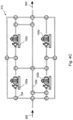
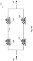
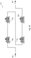
- a cluster 212 that includes four identical pumps 102a, 102b, 102c, 102d (collectively 102) as described above could be configured by an HRM controller 200 to be entirely in parallel for container pressures up to 2,75 bar (40 psi), as illustrated by Fig. 4A .
- the flow path for this configuration is illustrated by Fig. 4B .
- the controller 200 can then cause the valves 104 in the HRM plumbing system to reconfigure the pumps 102 into a series/parallel arrangement, as illustrated in Fig. 4C .
- the flow path 204 for this configuration is illustrated in Fig. 4D .
- the controller 200 can configure the pumps 200 so that they are all in series, thereby enabling the cluster 212 to continue operating at optimum efficiency for pressure differentials from 5,5 to 11 bar (80 to 160 psi).
- the cluster 212 includes only one type of HRM, for example one type of pump 102 for clusters that are used only for pumping fluids, only one type of turbine 202 for clusters that are used only for generating turboelectric energy, or only one type of hybrid HRM for clusters that are used both for pumping fluids and for generating turboelectric energy.
- the cluster 212 includes a limited range of HRM types, such as a plurality of identical pumps 102 and a plurality of identical turbines 202.
- an HRM cluster 212 can include at least one pump 102 that is optimized for pumping a pure liquid and another pump 102 that is optimized for pumping a hybrid fluid that includes gas and/or solids mixed with a liquid.
- the HRM controller 200 adjusts the HRM operating speeds and interconnections based upon information received from one or more information sources.
- the information can include, for example, the energy status at any given time of a green energy source such as a solar panel or wind turbine 500, i.e. how much excess energy is available to be stored, or how much previously stored energy is currently needed.
- the information can also include sensed information regarding energy being consumed 214 by pumps 102 and/or generated 210 by turbines 202 in the cluster 212, as well as information regarding the status of the process 108, such as pressures, flow rates, mass flow rates, geodetic fluid levels, static and dynamic fluid levels, static and dynamic fluid energies, fluid temperatures, fluid densities, fluid phases (gas, liquified, supercritical, solidified), amounts of solids and/or suspensions present in the process fluid, gas fractions, and/or solid/liquid ratios, among others.
- sensed information regarding energy being consumed 214 by pumps 102 and/or generated 210 by turbines 202 in the cluster 212 as well as information regarding the status of the process 108, such as pressures, flow rates, mass flow rates, geodetic fluid levels, static and dynamic fluid levels, static and dynamic fluid energies, fluid temperatures, fluid densities, fluid phases (gas, liquified, supercritical, solidified), amounts of solids and/or suspensions present in the process fluid, gas fractions,
- the HRM controller 200 also monitors 208 the health of the HRMs in the cluster 212, for example by monitoring bearing temperatures, noise levels, vibrations, wear rates, and component deflections. The HRM controller is thereby able to predict when an HRM is nearing failure and should be repaired or replaced. Similarly, in various embodiments the HRM controller 200 monitors 208 the health of the overall process 108 with which the HRM cluster 200 is associated, for example detecting leaks and other problems by monitoring pressures, temperatures, and/or flow rates at various points in the process.
Landscapes
- Engineering & Computer Science (AREA)
- General Engineering & Computer Science (AREA)
- Mechanical Engineering (AREA)
- Chemical & Material Sciences (AREA)
- Combustion & Propulsion (AREA)
- Physics & Mathematics (AREA)
- Fluid Mechanics (AREA)
- General Physics & Mathematics (AREA)
- Automation & Control Theory (AREA)
- Control Of Turbines (AREA)
- Control Of Positive-Displacement Pumps (AREA)
- Details Of Reciprocating Pumps (AREA)
Description
- The invention relates to pumps and turbines, and more particularly, to pumps and turbines that are required to maintain high efficiency over a wide range of conditions of service.
- With reference to
Fig. 1 ,pumps 102, turbines, and combination pump-turbines, referred to herein generically as "hydraulic rotating machinery" or "HRM," are traditionally operated at a fixed rotating speed, which is determined by the driving motor type and/or by the frequency of thepower 110 derived from theelectrical supply net 100. While an HRM can have a relatively wide condition of service ("COS") range over which it can be operated, optimal efficiency is typically realized only when the COS is a close match to the "best efficiency point" or BEP of the HRM, which is typically defined in terms of specified ranges of flow rate, flow volume, inlet and outlet pressure, inlet and outlet temperature, and sometimes also gas fraction and solid/liquid fraction, among other conditions. - If the COS that is demanded by a
process 108 deviates too far from the BEP of the HRM, the HRM will run at a much lower hydraulic efficiency. Also, an HRM can sometimes be subject to increased wear and reduced operating life when the COS is far from the BEP, due to resulting forces such as bearing loads and vibration levels. In addition, the only way to control thehydraulic output 112 of such fixed speed HRMs is to usethrottle valves 104, controlled for example by the measurements of aflow rate sensor 106, which introduces further energy losses. - One approach to maintaining HRM efficiency over wider COS ranges is to implement an HRM that can be driven at variable speeds. By changing the operating speed of a variable speed HRM, the BEP of the HRM can be shifted so that it remains close to a varying COS, thereby optimizing the overall efficiency of the process to which the HRM is applied. However, this approach can still be insufficient for some applications that require efficient operation over a very wide COS range.
- Technologies for green energy storage and recovery can require the operation of HRMs over especially wide COS ranges. HRMs are typically used in these technologies both to store energy (pumping mode) and recover the energy (turbine mode). For example, excess energy can be used to pump water from a low-lying reservoir to an elevated reservoir during times of low energy demand, and then turbines can be used to recapture the energy as the water is allowed to flow from the elevated reservoir back to the low-lying reservoir during periods of high energy demand.
- Similarly, HRMs can be used to pressurize and/or liquify a gas within a storage container during times when excess energy is available, and then the stored gas can be allowed to vaporize and/or expand during periods of high energy demand so that it can be used to operate a turbine. For example, energy can be stored by compressing carbon dioxide into a supercritical liquid state within a holding tank, and then vaporizing the carbon dioxide and directing the resulting gas through a turbine to recover the saved energy.
- As another example, HRMs can be used to drive heat pump cycles that store energy by heating or cooling a thermal storage medium. In each case, a separate pump and turbine can be implemented, or a dual mode pump/turbine HRM can be used to meet the requirements of both the energy storage cycle and the energy recovery cycle of an energy storage system.
- The full cycle of energy storage and subsequent energy recovery in such systems is referred to as the "round trip," and the efficiency of the round trip is called the "round trip efficiency" or "RTE." The RTE is defined as the ratio of the energy which can be recovered by the energy storage process, divided by the energy that was required to store the same energy. For example, if 100 MWH are used to store energy, and 80 MWh can be recovered from the stored energy as usable energy, the RTE is 80MWh / 100MWh * 100% = 80%. The optimization of the RTE is extremely important for the economics of any given energy storage and recovery process, including green energy systems that require HRM operation over wide COS ranges.
- Document
US 2015/260151 A1 discloses a system for controlling water turbine generator for waterworks. DocumentUS 2018/313324 A1 discloses a stepwise operating parallel type small hydro power generation system having fixed flow path. - What is needed, therefore, is an HRM solution that can provide optimal hydraulic energy efficiency over a very wide COS range.
- The present invention is a "hydraulic rotating machinery" ("HRM") system according to the related appended claims, that can provide optimal hydraulic energy efficiency over a very wide condition of service ("COS") range. In energy storage embodiments, the invention provides maximal round-trip efficiency ("RTE") for energy storage and recovery.
- The invention comprises a plurality, or "cluster," of variable speed HRMs having operating speeds that are independently controlled by an HRM controller. The HRMs in the cluster are interconnected with each other by an HRM plumbing system that includes an inlet, an outlet, and one or more valves that can be actuated by the HRM controller to configure a flow path through which a process fluid flows from the inlet to the outlet via one or more of the HRMs in the cluster. By actively selecting the HRMs that are included in the flow path, the interconnections therebetween, and the operating speeds thereof, the HRM controller is able to ensure that the HRM cluster continues to operate at optimal efficiency as the COS fluctuates over a very wide range.
- The following is a very simple example directed to a hypothetical HRM cluster comprising two identical, variable speed pumps, where the HRM cluster is used to store energy resulting from excess capacity of a green energy source by compressing a gas into a storage container. In this example, the operating speed of each of the pumps can be varied so as to maintain optimal efficiency when the volumetric flow rate through the pump is between 51 and 85 m3/h (30 and 50 cubic feet per minute (cfm)), and the output pressure is between 0 and 2,75 bar (0 and 40 psi) higher than the input pressure. As the process begins, the HRM controller has the option of either bypassing one of the pumps and adjusting the speed of the other pump to deliver gas to the storage container at 51-85 m3/h (30-50 cfm), or connecting the two pumps in parallel to deliver the gas to the storage container at a flow rate of 102-170 m3/h (60-100 cfm). The choice between these two options may depend, for example, on the amount of excess energy that is currently available from the green energy system.
- Once the pressure in the storage container reaches 2,75 bar (40 psi), the HRM controller reconfigures the pumps into a series configuration, and adjusts their operating speeds such that they are each efficiently pumping between 51 and 85 m3/h (30 and 50 cfm) over a pressure differential of 1,37 bar (20 psi) per pump. As the pressure within the storage container continues to rise above 2,75 bar (40 psi), the operating speeds of the two pumps are varied so as to maintain optimum energy efficiency. In this series configuration, by controlling the operating speeds of the pumps, optimal hydraulic efficiency of the HRM cluster can be maintained up to a maximum of 2,75 bar (40 psi) per pump, i.e. 5,5 bar (80 psi) total.
- This approach can be extended to clusters of more than two pumps as needed. For example, a cluster that includes four identical pumps as described above could be configured by an HRM controller to be entirely in parallel for container pressures up to 2,75 bar (40 psi), in a series/parallel arrangement from 2,75 to 5,5 bar (40 to 80 psi), and all in series for pressures from 5,5 to 11 bar (80 to 160 psi), where the operating rates of the HRMs would be adjusted as needed such that each of the pumps operates at or near its BEP over this entire range. In the same way, this approach can be extended to clusters that include any combination of pumps, turbines, and/or hybrid pump/turbine HRMs ("hybrid" HRMs).
- In some embodiments, the cluster includes only one type of HRM, for example one type of pump for clusters that are used only for pumping fluids, only one type of turbine for clusters that are used only for generating turboelectric energy, or only one type of hybrid HRM for clusters that are used both for pumping fluids and for generating turboelectric energy. In similar embodiments, the cluster includes a limited range of HRM types, such as a plurality of identical pumps and a plurality of identical turbines.
- Limiting the number of different types of HRM that are included in a cluster can simplify the support and maintenance of the cluster and reduces costs, because only a relatively small inventory of "spare" HRMs is required to enable failed units in the cluster to be quickly replaced. This approach also enables the cluster to be readily expanded as needed, simply by adding additional HRMs from inventory to the cluster, and making corresponding extensions to the HRM plumbing system and controller, thereby enabling the cluster to be readily adapted to changing requirements of the process.
- Other embodiments include HRM clusters comprising a plurality of different types of pumps, turbines, and/or hybrid HRMs having different BEPs, as well as HRMs that can tolerate different gas fractions and/or solid/liquid ratios. This approach can reduce the number of HRMs that are required to enable the cluster to maintain optimal energy efficiency over a wide range of COS. For example, if the process fluid is normally a liquid, but sometimes also includes gas and/or solids, then an HRM cluster might include at least one pump that is optimized for pumping a pure liquid and another pump that is optimized for pumping a hybrid fluid that includes gas and/or solids mixed with a liquid.
- According to the present invention, the controller adjusts the operating speeds and interconnections of the HRMs based upon information received from one or more information sources. The information can include, for example, the energy status at any given time of a green energy source such as a solar panel or wind turbine, i.e. how much excess energy is available to be stored, or how much previously stored energy is currently needed. The information can also include sensed information regarding energy being consumed by pumps and/or generated by turbines in the cluster, as well as various process fluid parameters, such as pressures, volumetric flow rates, mass flow rates, geodetic fluid levels, static and dynamic fluid levels, static and dynamic fluid energies, fluid temperatures, fluid densities, fluid phases (gas, liquified, supercritical, solidified), amounts of solids and/or suspensions present in the fluid, gas fractions, and/or solid/liquid ratios, among others.
- The HRM controller applies a process-dependent algorithm to these inputs so as to determine which of the HRMs in the cluster should be included in the flow path, how they should be interconnected, and at what speed each of the HRMs should be operated, thereby ensuring that each of the HRMs in the flow path continues to operate at or near its "best efficiency point" (BEP) as the conditions of service vary over a wide range.
- In embodiments, the HRM controller also monitors the health of the HRMs in the clusters, for example by monitoring bearing temperatures, noise levels, vibrations, wear rates, and component deflections. The HRM controller is thereby able to predict when an HRM is nearing failure and should be repaired or replaced. Similarly, in various embodiments the HRM controller monitors the health of the overall process with which the HRM cluster is associated, for example detecting leaks and other problems by monitoring pressures, temperatures, and/or flow rates at various points in the process.
- One general aspect of the present invention is a hydraulic rotating machinery (HRM) system that is configured to control a process fluid of a process, said process fluid having widely varying conditions of service (COS). The HRM system includes a controller, an HRM cluster comprising a plurality of HRMs having variable operating speeds, each of the HRMs being a pump, a turbine, or a hybrid pump/turbine, the operating speeds of the HRMs being controlled by the controller, an HRM plumbing system, the HRMs being interconnectable by the HRM plumbing system to form a flow path through which the process fluid can flow from an inlet of the HRM plumbing system to an outlet of the HRM plumbing system, a plurality of valves included in the HRM plumbing system, the controller being able to actuate the valves so as to control a selection of the HRMs that are included in the flow path and an arrangement in which the HRMs of the selection are included in the flow path, and non-transient media cooperative with the controller.
- The non-transient media contains instructions that, when executed by the controller, cause the controller to accept information regarding at least one of a status of the process and the COS of the process fluid, and according to said information, control the operating speeds of the HRMs and the selection and arrangement of the HRMs in the flow path so as to continuously satisfy at least one requirement of the process while ensuring that the HRMs in the flow path operate substantially at their optimal hydraulic efficiency points over said widely varying COS of the process fluid.
- In embodiments, all of the HRMs in the plurality of HRMs are identical to each other.
- In any of the above embodiments, the plurality of HRMs can include pumps and turbines, all of the pumps in the plurality of HRMs being identical to each other, and all of the turbines in the plurality of HRMs being identical to each other.
- In any of the above embodiments, the controller can be able to change the configuration of the flow path such that an interconnection of a pair of the HRMs in the flow path is changed between a parallel interconnection and a serial interconnection.
- In any of the above embodiments, the controller can be able to change the configuration of the flow path such that an interconnection between four of the HRMs in the cluster is changed between a fully parallel interconnection, a series-parallel interconnection, and a fully series interconnection.
- In any of the above embodiments, the process can be an energy generating process, and the HRM system can be configured to store a surplus energy output of the process when the process is subject to a low energy demand, and to recover said stored energy and supply the recovered energy to the process when the process is subject to a high energy demand.
- In any of the above embodiments, the cluster can include at least one HRM that is configured for efficient operation upon a process fluid that is a mixture of a liquid and a gas.
- In any of the above embodiments, the cluster can include at least one HRM that is configured for efficient operation upon a process fluid that is a liquid mixed with solids.
- In any of the above embodiments, the cluster can include a first pump having first operating characteristics and a second pump having second operating characteristics that are distinct from the first operating characteristics.
- In any of the above embodiments, the cluster includes a first turbine having first operating characteristics and a second turbine having second operating characteristics that are distinct from the first operating characteristics.
- In any of the above embodiments, the cluster can include a first hybrid pump/turbine having first operating characteristics and a second hybrid pump/turbine having second operating characteristics that are distinct from the first operating characteristics.
- In any of the above embodiments, the information received by the controller can include information pertaining to an operating health of an HRM in the cluster, and wherein the instructions, when executed by the controller, further cause the controller to predict a time until failure of the HRM.
- A second general aspect of the present invention is a method of efficiently controlling a process fluid of a process according to the related appended claim, said process fluid having widely varying conditions of service (COS). The method includes providing a controller, providing a plurality of HRMs having variable operating speeds, each of the HRMs being a pump, a turbine, or a hybrid pump/turbine, interconnecting the HRMs via an HRM plumbing system to form an HRM cluster, the HRM plumbing system comprising a plurality of valves, controlling of the valves by the controller so as to configure a flow path through which the process fluid can flow from an inlet of the HRM plumbing system to an outlet of the HRM plumbing system, said flow path comprising a selection of the HRMs of the cluster arranged in an HRM arrangement, causing the process fluid to flow through the flow path, receiving by the controller of information regarding at least one of a status of the process and the COS of the process fluid, and according to said information, controlling by the controller of the operating speeds of the HRMs and the selection and arrangement of the HRMs in the flow path so as to continuously satisfy at least one requirement of the process while ensuring that the HRMs in the flow path operate substantially at their optimal hydraulic efficiency points over said widely varying COS of the process fluid.
- The features and advantages described herein are not all-inclusive and, in particular, many additional features and advantages will be apparent to one of ordinary skill in the art in view of the drawings, specification, and claims. Moreover, it should be noted that the language used in the specification has been principally selected for readability and instructional purposes, and not to limit the scope of the inventive subject matter.
-
-
Fig. 1 illustrates control of a process fluid by an HRM in an example of the prior art; -
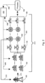
Fig. 2 illustrates an embodiment of the present invention in which an HRM cluster stores and then retrieves energy in support of a green energy system; -
Fig. 3A illustrates an HRM cluster comprising two HRMs, where the HRMs are connected in parallel by the HRM plumbing system according to an embodiment of the present invention; -
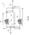
Fig. 3B illustrates an HRM cluster comprising two HRMs, where the HRMs are connected in series by the HRM plumbing system; -
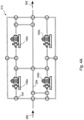
Fig. 4A is a block diagram of an HRM cluster comprising four HRMs, where the HRMs are connected in parallel by the HRM plumbing system according to an embodiment of the present invention; -
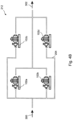
Fig. 4B is a simplified block diagram of the cluster ofFig. 4A , showing the flow path through the cluster; -
Fig. 4C is a block diagram of an HRM cluster comprising four HRMs, where the HRMs are connected in a series-parallel arrangement by the HRM plumbing system according to an embodiment of the present invention; -
Fig. 4D is a simplified block diagram of the cluster ofFig. 4C , showing the flow path through the cluster; -
Fig. 4E is a block diagram of an HRM cluster comprising four HRMs, where the HRMs are connected in series by the HRM plumbing system according to an embodiment of the present invention; -
Fig. 4F is a simplified block diagram of the cluster ofFig. 4E , showing the flow path through the cluster; and -
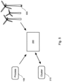
Fig. 5 is a block diagram that illustrates an exchange of information between a controller and an HRM cluster, a process, and a green energy system; - The present invention is a "hydraulic rotating machinery" ("HRM") system that can provide high energy efficiency over a very wide condition of service ("COS") range. In energy storage embodiments, the invention provides maximal round-trip efficiency ("RTE") for energy storage and recovery.
- With reference to
Figs. 2 and3A , the invention comprises a plurality, or "cluster" 212, ofvariable speed HRMs HRM controller 200. TheHRMs cluster 212 are interconnected with each other by anHRM plumbing system 204 that includes aninlet 300, anoutlet 302, and one ormore valves 104 that can be actuated by theHRM controller 200 to configure aflow path 306 through which a process fluid flows from theinlet 300 to theoutlet 302 via one or more of theHRMs cluster 212. By actively selecting which of theHRMs flow path 306, the interconnections therebetween, and the operating speeds thereof, theHRM controller 200 is able to ensure that theHRM cluster 212 continues to operate at optimal efficiency as the COS fluctuates over a very wide range. -
Figs. 3A - 3B illustrate a very simple example of ahypothetical HRM cluster 212 comprising two identical,variable speed pumps HRM cluster 212 is used to store energy resulting from excess capacity of a green energy source by pumping water into a storage compressor, thereby compressing a gas that is contained within the storage container (not shown). In this hypothetical example, the operating speed of each of thepumps pump HRM controller 200 has the option of either bypassing one of thepumps 102b and adjusting the speed of theother pump 102a to deliver gas to the storage container at 51-85 m3/h (30-50 cfm).Fig. 3A illustrates the other possibility, which is to cause thevalves 104 to interconnect the twopumps - With reference to
Fig. 3B , once the pressure in the storage container reaches 2,75 bar (40 psi), the HRM controller causes thevalves 104 to reconfigure thepumps pumps Fig. 3B , by controlling the operating speeds of the pumps, optimal efficiency of theHRM cluster 212 can be maintained up to a maximum of 2,75 bar (40 psi) per pump, i.e. 5,5 bar (80 psi) total. - This approach can be extended to clusters of more than two pumps so as to cover even wider COS ranges as needed. For example, with reference to
Figs. 4A - 4B , acluster 212 that includes fouridentical pumps HRM controller 200 to be entirely in parallel for container pressures up to 2,75 bar (40 psi), as illustrated byFig. 4A . The flow path for this configuration is illustrated byFig. 4B . As the pressure differential varies from 2,75 to 5,5 bar (40 to 80 psi), thecontroller 200 can then cause thevalves 104 in the HRM plumbing system to reconfigure thepumps 102 into a series/parallel arrangement, as illustrated inFig. 4C . Theflow path 204 for this configuration is illustrated inFig. 4D . Once the pressure differential rises above 5,5 bar (80 psi), thecontroller 200 can configure thepumps 200 so that they are all in series, thereby enabling thecluster 212 to continue operating at optimum efficiency for pressure differentials from 5,5 to 11 bar (80 to 160 psi). According to this simple example, by varying both the operating speeds of the pumps and the interconnections between the pumps, thecontroller 200 is able to ensure that each of the pumps continues to operate at or near its BEP over this entire range. In the same way, this approach can be extended to clusters that include any combination of pumps, turbines, and/or hybrid pump/turbine HRMs ("hybrid" HRMs). - In some embodiments, the
cluster 212 includes only one type of HRM, for example one type ofpump 102 for clusters that are used only for pumping fluids, only one type ofturbine 202 for clusters that are used only for generating turboelectric energy, or only one type of hybrid HRM for clusters that are used both for pumping fluids and for generating turboelectric energy. In similar embodiments, thecluster 212 includes a limited range of HRM types, such as a plurality ofidentical pumps 102 and a plurality ofidentical turbines 202. - Limiting the number of different types of HRM that are included in a
cluster 212 can simplify the support and maintenance of thecluster 212 and reduces costs, because only a relatively small inventory of "spare" HRMs is required to enable failed units in thecluster 212 to be quickly replaced. This modular approach also enables thecluster 212 to be readily expanded as need, simply by adding additional HRMs from inventory to thecluster 212, with appropriate extensions to theHRM plumbing system 204 and to thecontroller 200, thereby enabling thecluster 212 to be readily adapted to changing requirements of the process. - Other embodiments include clusters comprising a plurality of different types of
pumps 102,turbines 202, and/or hybrid HRMs having different BEPs, as well as HRMs that can tolerate different gas fractions and/or solid/liquid ratios. This approach can reduce the number of HRMs that are required to enable thecluster 212 to maintain optimal energy efficiency over a wide range of COS. For example, if the process fluid is normally a liquid, but sometimes also includes gas and/or solids, then anHRM cluster 212 can include at least onepump 102 that is optimized for pumping a pure liquid and anotherpump 102 that is optimized for pumping a hybrid fluid that includes gas and/or solids mixed with a liquid. - With reference to
Fig. 5 , theHRM controller 200 adjusts the HRM operating speeds and interconnections based upon information received from one or more information sources. The information can include, for example, the energy status at any given time of a green energy source such as a solar panel orwind turbine 500, i.e. how much excess energy is available to be stored, or how much previously stored energy is currently needed. The information can also include sensed information regarding energy being consumed 214 bypumps 102 and/or generated 210 byturbines 202 in thecluster 212, as well as information regarding the status of theprocess 108, such as pressures, flow rates, mass flow rates, geodetic fluid levels, static and dynamic fluid levels, static and dynamic fluid energies, fluid temperatures, fluid densities, fluid phases (gas, liquified, supercritical, solidified), amounts of solids and/or suspensions present in the process fluid, gas fractions, and/or solid/liquid ratios, among others. - The HRM controller applies a process-dependent algorithm to this information so as to determine which of the HRMs in the
cluster 212 should be included in the flow path, how they should be interconnected, and at what speed each of the HRMs should be operated, thereby ensuring that each of the HRMs in the flow path operates at or near its "best efficiency point" (BEP). - In embodiments, the
HRM controller 200 also monitors 208 the health of the HRMs in thecluster 212, for example by monitoring bearing temperatures, noise levels, vibrations, wear rates, and component deflections. The HRM controller is thereby able to predict when an HRM is nearing failure and should be repaired or replaced. Similarly, in various embodiments theHRM controller 200monitors 208 the health of theoverall process 108 with which theHRM cluster 200 is associated, for example detecting leaks and other problems by monitoring pressures, temperatures, and/or flow rates at various points in the process. - The foregoing description of the embodiments of the invention has been presented for the purposes of illustration and description. Each and every page of this submission, and all contents thereon, however characterized, identified, or numbered, is considered a substantive part of this application for all purposes, irrespective of form or placement within the application. This specification is not intended to be exhaustive or to limit the invention to the precise form disclosed. Many modifications and variations are possible in light of this disclosure.
- Although the present application is shown in a limited number of forms, the scope of the invention is not limited to just these forms, but is amenable to various changes and modifications. The disclosure presented herein does not explicitly disclose all possible combinations of features that fall within the scope of the invention. The features disclosed herein for the various embodiments can generally be interchanged and combined into any combinations that are not self-contradictory without departing from the scope of the invention, defined in the claims. In particular,
the limitations presented in dependent claims below can be combined with their corresponding independent claims in any number and in any order without departing from the scope of the invention, unless the dependent claims are logically incompatible with each other.
Claims (13)
- A hydraulic rotating machinery (HRM) system that is configured to control a process fluid of a process, said process fluid having widely varying conditions of service (COS), the HRM system comprising:a controller (200);an HRM cluster (212) comprising a plurality of HRMs (102, 202) having variable operating speeds, each of the HRMs (102, 202) being a pump (102), a turbine (202), or a hybrid pump/turbine, the operating speeds of the HRMs (102, 202) being controlled by the controller (200);an HRM plumbing system (204), the HRMs (102, 202) being interconnectable by the HRM plumbing system (204) to form a flow path (306) through which the process fluid can flow from an inlet (300) of the HRM plumbing system (204) to an outlet (302) of the HRM plumbing system (204);a plurality of valves (104) included in the HRM plumbing system (204), the controller (200) being able to actuate the valves (104) so as to control a selection of the HRMs (102, 202) that are included in the flow path (306) and an arrangement in which the HRMs (102, 202) of the selection are included in the flow path (306);wherein the controller is further able to switch interconnections between four of the HRMs in the cluster such that, for all possible combinations of two selected HRMs of the four HRMs, the controller is able to actuate the valves so as to connect the two selected HRMs in series while the other two HRMs of the four HRMs are bypassed; andnon-transient media cooperative with the controller (200), the non-transient media containing instructions that, when executed by the controller (200), cause the controller (200) to:accept information regarding at least one of a status of the process and the COS of the process fluid; andaccording to said information, control the operating speeds of the HRMs (102, 202) and the selection and arrangement of the HRMs (102, 202) in the flow path (306) so as to continuously satisfy at least one requirement of the process while ensuring that the HRMs (102, 202) in the flow path (306) operate substantially at their optimal hydraulic efficiency points over said widely varying COS of the process fluid.
- The HRM system of claim 1, wherein all of the HRMs (102, 202) in the plurality of HRMs (102, 202) are identical to each other.
- The HRM system of any preceding claim, wherein the plurality of HRMs (102, 202) includes pumps (102) and turbines (202), all of the pumps (102) in the plurality of HRMs (102, 202) being identical to each other, and all of the turbines (202) in the plurality of HRMs (102, 202) being identical to each other.
- The HRM system of any preceding claim, wherein the controller (200) is able to change the configuration of the flow path such that an interconnection of a pair of the HRMs (102, 202) in the flow path is changed between a parallel interconnection and a serial interconnection.
- The HRM system of any preceding claim, wherein the controller (200) is able to change the configuration of the flow path such that an interconnection between four of the HRMs (102, 202) in the cluster (212) is changed between a fully parallel interconnection, a series-parallel interconnection, and a fully series interconnection.
- The HRM system of any preceding claim, wherein the process is an energy generating process, and the HRM system is configured to store a surplus energy output of the process when the process is subject to a low energy demand, and to recover said stored energy and supply the recovered energy to the process when the process is subject to a high energy demand.
- The HRM system of any preceding claim, wherein the cluster (212) includes at least one HRM that is configured for efficient operation upon a process fluid that is a mixture of a liquid and a gas.
- The HRM system of any preceding claim, wherein the cluster (212) includes at least one HRM that is configured for efficient operation upon a process fluid that is a liquid mixed with solids.
- The HRM system of any preceding claim except claim 2 or 3, wherein the cluster (212) includes a first pump (102) having first operating characteristics and a second pump (102) having second operating characteristics that are distinct from the first operating characteristics.
- The HRM system of any preceding claim except claim 2 or 3, wherein the cluster (212) includes a first turbine (202) having first operating characteristics and a second turbine (202) having second operating characteristics that are distinct from the first operating characteristics.
- The HRM system of any preceding claim except claim 2 or 3, wherein the cluster (212) includes a first hybrid pump/turbine having first operating characteristics and a second hybrid pump/turbine having second operating characteristics that are distinct from the first operating characteristics.
- The HRM system of any preceding claim, wherein the information received by the controller (200) includes information pertaining to an operating health of an HRM in the cluster (212), and wherein the instructions, when executed by the controller (200), further cause the controller to predict a time until failure of the HRM.
- A method of efficiently controlling a process fluid of a process, said process fluid having widely varying conditions of service (COS), the method comprising:providing a controller (200);providing a plurality of HRMs (102, 202) having variable operating speeds, each of the HRMs (102, 202) being a pump (102), a turbine (202), or a hybrid pump/turbine;interconnecting the HRMs (102, 202) via an HRM plumbing system (204) to form an HRM cluster (212), the HRM plumbing system comprising a plurality of valves (104);controlling of the valves (104) by the controller (200) so as to configure a flow path (306) through which the process fluid can flow from an inlet (300) of the HRM plumbing system (204) to an outlet (302) of the HRM plumbing system (204), said flow path comprising a selection of the HRMs (102, 202) of the cluster (212) arranged in an HRM arrangement, wherein the controller is further able to switch interconnections between four of the HRMs in the cluster such that, for all possible combinations of two selected HRMs of the four HRMs, the controller is able to actuate the valves so as to connect the two selected HRMs in series while the other two HRMs of the four HRMs are bypassed;causing the process fluid to flow through the flow path (306);receiving by the controller (200) of information regarding at least one of a status of the process and the COS of the process fluid; andaccording to said information, controlling by the controller (200) of the operating speeds of the HRMs (102, 202) and the selection and arrangement of the HRMs (102, 202) in the flow path (306) so as to continuously satisfy at least one requirement of the process while ensuring that the HRMs (102, 202) in the flow path (306) operate substantially at their optimal hydraulic efficiency points over said widely varying COS of the process fluid.
Applications Claiming Priority (1)
| Application Number | Priority Date | Filing Date | Title |
|---|---|---|---|
| US17/863,591 US12292026B2 (en) | 2022-07-13 | 2022-07-13 | Variable speed reconfigurable pump/turbine clusters |
Publications (3)
| Publication Number | Publication Date |
|---|---|
| EP4310317A1 EP4310317A1 (en) | 2024-01-24 |
| EP4310317B1 true EP4310317B1 (en) | 2025-07-02 |
| EP4310317C0 EP4310317C0 (en) | 2025-07-02 |
Family
ID=87245732
Family Applications (1)
| Application Number | Title | Priority Date | Filing Date |
|---|---|---|---|
| EP23184819.3A Active EP4310317B1 (en) | 2022-07-13 | 2023-07-11 | Variable speed reconfigurable pump/turbine clusters |
Country Status (7)
| Country | Link |
|---|---|
| US (1) | US12292026B2 (en) |
| EP (1) | EP4310317B1 (en) |
| JP (1) | JP2024012136A (en) |
| KR (1) | KR102812598B1 (en) |
| CN (1) | CN117404441A (en) |
| AU (1) | AU2023204221B2 (en) |
| IL (1) | IL304483B2 (en) |
Citations (1)
| Publication number | Priority date | Publication date | Assignee | Title |
|---|---|---|---|---|
| US20180313324A1 (en) * | 2017-04-28 | 2018-11-01 | Keunnamu Co., Ltd. | Stepwise operating parallel type small hydro power generation system having fixed flow path |
Family Cites Families (57)
| Publication number | Priority date | Publication date | Assignee | Title |
|---|---|---|---|---|
| US3006288A (en) | 1952-09-16 | 1961-10-31 | Brown Owen | System for high-speed transport |
| US2973894A (en) | 1957-06-17 | 1961-03-07 | Turbo Res Corp | Centrifugal compressor for starting jet engines |
| CH503900A (en) * | 1965-05-24 | 1971-02-28 | Vevey Atel Const Mec | Method for adjusting a hydraulic machine with variable-pitch propeller and installation for implementing this method |
| US3922110A (en) | 1974-01-28 | 1975-11-25 | Henry Huse | Multi-stage vacuum pump |
| DE2430314C3 (en) | 1974-06-24 | 1982-11-25 | Siemens AG, 1000 Berlin und 8000 München | Liquid ring vacuum pump with upstream compressor |
| US4505647A (en) | 1978-01-26 | 1985-03-19 | Grumman Allied Industries, Inc. | Vacuum pumping system |
| CH625854A5 (en) * | 1978-11-17 | 1981-10-15 | Vevey Atel Const Mec | Reversible hydroelectric machine |
| US4699570A (en) | 1986-03-07 | 1987-10-13 | Itt Industries, Inc | Vacuum pump system |
| US4850809A (en) | 1988-04-14 | 1989-07-25 | Smith William C | Air operated low pressure spraying system |
| JPH02130269A (en) * | 1988-11-09 | 1990-05-18 | Toshiba Eng Co Ltd | Cascade type hydraulic power generation set |
| DE19500823A1 (en) | 1995-01-13 | 1996-07-18 | Sgi Prozess Technik Gmbh | Vacuum pumping station |
| DE19524609A1 (en) | 1995-07-06 | 1997-01-09 | Leybold Ag | Device for the rapid evacuation of a vacuum chamber |
| JP3374696B2 (en) * | 1997-03-03 | 2003-02-10 | 株式会社日立製作所 | Pump turbine |
| US5944049A (en) | 1997-07-15 | 1999-08-31 | Applied Materials, Inc. | Apparatus and method for regulating a pressure in a chamber |
| US6602044B1 (en) * | 1999-10-29 | 2003-08-05 | Takao Kuwabara | Pump turbine, method of controlling thereof, and method of stopping thereof |
| US6633828B2 (en) * | 2001-03-21 | 2003-10-14 | Honeywell International Inc. | Speed signal variance detection fault system and method |
| JP2002295356A (en) * | 2001-03-30 | 2002-10-09 | Tokyo Electric Power Co Inc:The | Multi-stage hydroelectric generator |
| US6589023B2 (en) | 2001-10-09 | 2003-07-08 | Applied Materials, Inc. | Device and method for reducing vacuum pump energy consumption |
| GB0214273D0 (en) | 2002-06-20 | 2002-07-31 | Boc Group Plc | Apparatus for controlling the pressure in a process chamber and method of operating same |
| JP4398167B2 (en) | 2003-03-04 | 2010-01-13 | 株式会社荏原製作所 | Power generation equipment using pump reverse turbine |
| US20060266038A1 (en) * | 2003-05-29 | 2006-11-30 | Krouse Wayne F | Machine and system for power generation through movement of water |
| JP4610866B2 (en) * | 2003-06-11 | 2011-01-12 | 株式会社日立産機システム | Energy recovery system and control method, and multiple turbine generator system and operation control method |
| US7021888B2 (en) | 2003-12-16 | 2006-04-04 | Universities Research Association, Inc. | Ultra-high speed vacuum pump system with first stage turbofan and second stage turbomolecular pump |
| WO2007133774A2 (en) | 2006-05-15 | 2007-11-22 | Federal Signal Corporation | Dust separation system for use with mobile equipment |
| WO2009061443A1 (en) | 2007-11-08 | 2009-05-14 | Us Airflow | Compression apparatus |
| US8016548B2 (en) * | 2007-03-30 | 2011-09-13 | Mark R. Ziegenfuss | Water supply tunnel secondary purpose turbine electric power generator system |
| JP5032220B2 (en) | 2007-06-30 | 2012-09-26 | 三州産業株式会社 | Leaf tobacco dry leaf take-off equipment |
| JP2010229962A (en) * | 2009-03-30 | 2010-10-14 | Mitsubishi Electric Corp | Speed control device for water turbine or pump turbine |
| US20100270801A1 (en) * | 2009-04-28 | 2010-10-28 | Liu Kuo-Shen | Electricity storage and recovery system |
| JP5450110B2 (en) * | 2010-01-07 | 2014-03-26 | 日立三菱水力株式会社 | Power generation system controller for variable speed pumped storage power plant |
| JP5667863B2 (en) * | 2010-12-20 | 2015-02-12 | 四国電力株式会社 | Output control device, output control method, and water turbine power generation system including the output control device |
| JP5406234B2 (en) | 2011-03-02 | 2014-02-05 | 網矢 貞幸 | tunnel |
| US20120326443A1 (en) * | 2011-06-21 | 2012-12-27 | Genalta Power, Inc. | Variable speed power generation from industrial fluid energy sources |
| KR101544963B1 (en) | 2014-03-17 | 2015-08-18 | 엘에스산전 주식회사 | System for controlling water turbine generator for waterworks |
| PE20170240A1 (en) * | 2014-04-23 | 2017-03-30 | Alstom Renewable Technologies | HYDRAULIC INSTALLATION AND METHOD TO MAKE AN INSTALLATION OF THIS TYPE WORK |
| AU2015334312B2 (en) * | 2014-10-23 | 2018-10-04 | Daikin Industries, Ltd. | Fluid system |
| JP2016125773A (en) | 2015-01-05 | 2016-07-11 | 三菱重工業株式会社 | Liquefied gas cooling device |
| US9599235B2 (en) | 2015-02-08 | 2017-03-21 | Hyperloop Technologies, Inc. | Gate valves and airlocks for a transportation system |
| US9764648B2 (en) | 2015-02-08 | 2017-09-19 | Hyperloop Technologies, Inc. | Power supply system and method for a movable vehicle within a structure |
| US10094381B2 (en) | 2015-06-05 | 2018-10-09 | Agilent Technologies, Inc. | Vacuum pump system with light gas pumping and leak detection apparatus comprising the same |
| US10408186B2 (en) * | 2015-11-17 | 2019-09-10 | Adebukola Olatunde | Combined pump and turbine |
| EP3387191B1 (en) | 2015-12-11 | 2019-11-06 | Grundfos Holding A/S | Ship lock system for a canal |
| US10794166B2 (en) | 2016-10-14 | 2020-10-06 | Dresser-Rand Company | Electric hydraulic fracturing system |
| US10612512B2 (en) * | 2016-12-28 | 2020-04-07 | North China Electric Power University (NCEPU) | Energy storage and power generation system and method |
| JP6473283B1 (en) | 2017-05-30 | 2019-02-20 | 株式会社アルバック | Vacuum pump |
| KR102338118B1 (en) * | 2017-09-22 | 2021-12-10 | 가부시키가이샤 히다치 산키시스템 | Hydropower grid linkage system |
| CN108035838B (en) * | 2017-12-07 | 2020-11-03 | 武汉四创自动控制技术有限责任公司 | Health state evaluation and optimization method for speed regulation system of water turbine of whole plant |
| US10865762B1 (en) | 2018-02-14 | 2020-12-15 | Mirko Dusan Vojnovic | Scalable fluid generator array |
| KR101920414B1 (en) | 2018-07-12 | 2018-11-20 | 한국진공주식회사 | Gate valve of Vacuum chamber apparatus |
| US10784658B2 (en) | 2018-09-06 | 2020-09-22 | General Electric Company | Mobile power generation restraint assembly |
| WO2020050675A1 (en) * | 2018-09-07 | 2020-03-12 | 김성식 | Conduit turbine for supporting conduit of water wheel rotational body, and hydroelectric generator having conduit turbines serially provided in multiple levels |
| CN109356647B (en) | 2018-12-03 | 2020-03-31 | 西京学院 | Ultra-thin vacuum pipeline traffic isolation door capable of being embedded into rail gap |
| WO2020123941A1 (en) * | 2018-12-14 | 2020-06-18 | Go Team CCR LLC | Apparatus and method for generation of electricity with pressurized water and air flow media |
| CA3128765A1 (en) * | 2019-02-08 | 2020-08-13 | Hydrostor Inc. | Over-pressurization for compressed air energy storage systems |
| CN111720253A (en) | 2019-03-21 | 2020-09-29 | 伟尔矿物澳大利亚私人有限公司 | Method and system for treating slurry |
| JP6849034B1 (en) * | 2019-09-26 | 2021-03-24 | ダイキン工業株式会社 | Hydropower system and generator control method |
| NL2027210B1 (en) * | 2020-12-23 | 2022-07-20 | Tree Energy Solutions B V | Energy storage system |
-
2022
- 2022-07-13 US US17/863,591 patent/US12292026B2/en active Active
-
2023
- 2023-06-30 AU AU2023204221A patent/AU2023204221B2/en active Active
- 2023-07-04 KR KR1020230086705A patent/KR102812598B1/en active Active
- 2023-07-07 JP JP2023112239A patent/JP2024012136A/en active Pending
- 2023-07-11 CN CN202310848189.9A patent/CN117404441A/en active Pending
- 2023-07-11 EP EP23184819.3A patent/EP4310317B1/en active Active
- 2023-07-13 IL IL304483A patent/IL304483B2/en unknown
Patent Citations (1)
| Publication number | Priority date | Publication date | Assignee | Title |
|---|---|---|---|---|
| US20180313324A1 (en) * | 2017-04-28 | 2018-11-01 | Keunnamu Co., Ltd. | Stepwise operating parallel type small hydro power generation system having fixed flow path |
Also Published As
| Publication number | Publication date |
|---|---|
| IL304483A (en) | 2024-02-01 |
| CN117404441A (en) | 2024-01-16 |
| US12292026B2 (en) | 2025-05-06 |
| KR20240009356A (en) | 2024-01-22 |
| AU2023204221A1 (en) | 2024-02-01 |
| IL304483B2 (en) | 2026-05-01 |
| KR102812598B1 (en) | 2025-05-23 |
| EP4310317C0 (en) | 2025-07-02 |
| IL304483B1 (en) | 2026-01-01 |
| JP2024012136A (en) | 2024-01-25 |
| US20240018934A1 (en) | 2024-01-18 |
| AU2023204221B2 (en) | 2024-06-13 |
| EP4310317A1 (en) | 2024-01-24 |
Similar Documents
| Publication | Publication Date | Title |
|---|---|---|
| US8375716B2 (en) | Operating a sub-sea organic Rankine cycle (ORC) system using individual pressure vessels | |
| JP2009138684A (en) | Rankine cycle equipment | |
| EP3758190A1 (en) | Compressed air energy storage and power generation device | |
| US20140088773A1 (en) | Systems and methods for part load control of electrical power generating systems | |
| CN116575993A (en) | Dual power system pumped thermoelectric storage with inventory control and purge | |
| Schneider | Selection, operation and control of a work exchanger energy recovery system based on the Singapore project | |
| WO2011076926A2 (en) | Compressed air energy storage system | |
| US3869857A (en) | Thermal power plant | |
| EP2824029B1 (en) | Waste heat recovery system for vessel | |
| AU2023204221B2 (en) | Variable speed reconfigurable pump/turbine clusters | |
| US6851265B2 (en) | Steam cooling control for a combined cycle power plant | |
| US11952941B2 (en) | Compressed air energy storage power generation device | |
| CN111608866B (en) | An Efficiency Analysis Method of Power Generation System | |
| CN109578093A (en) | For driving the driving equipment of acting machine | |
| KR20230092307A (en) | Carnot battery system | |
| CN111502890B (en) | A multi-stage power generation system and operation method thereof | |
| US20210178328A1 (en) | Method and system for performing reverse osmosis with integrated pump storage | |
| JP2025527416A (en) | Multi-stage pumps or turbines for controlling fluids with large variations in gas fraction | |
| JP6862514B2 (en) | Compressed air storage power generator | |
| CN120759727A (en) | Geothermal resource development system and method | |
| CN120487299A (en) | Underwater compressed air energy storage system considering multi-level gas storage structure | |
| WO2026062069A1 (en) | Method and plant for multi-stage gas compression | |
| KR20200140575A (en) | Heat exchange system and offshore structure having the same | |
| JP2011117600A (en) | System for controlling thrust affecting shaft | |
| Hartman | Network based control of fluid distribution systems |
Legal Events
| Date | Code | Title | Description |
|---|---|---|---|
| PUAI | Public reference made under article 153(3) epc to a published international application that has entered the european phase |
Free format text: ORIGINAL CODE: 0009012 |
|
| STAA | Information on the status of an ep patent application or granted ep patent |
Free format text: STATUS: REQUEST FOR EXAMINATION WAS MADE |
|
| 17P | Request for examination filed |
Effective date: 20230711 |
|
| AK | Designated contracting states |
Kind code of ref document: A1 Designated state(s): AL AT BE BG CH CY CZ DE DK EE ES FI FR GB GR HR HU IE IS IT LI LT LU LV MC ME MK MT NL NO PL PT RO RS SE SI SK SM TR |
|
| STAA | Information on the status of an ep patent application or granted ep patent |
Free format text: STATUS: EXAMINATION IS IN PROGRESS |
|
| 17Q | First examination report despatched |
Effective date: 20240730 |
|
| GRAP | Despatch of communication of intention to grant a patent |
Free format text: ORIGINAL CODE: EPIDOSNIGR1 |
|
| STAA | Information on the status of an ep patent application or granted ep patent |
Free format text: STATUS: GRANT OF PATENT IS INTENDED |
|
| INTG | Intention to grant announced |
Effective date: 20250331 |
|
| GRAS | Grant fee paid |
Free format text: ORIGINAL CODE: EPIDOSNIGR3 |
|
| GRAA | (expected) grant |
Free format text: ORIGINAL CODE: 0009210 |
|
| STAA | Information on the status of an ep patent application or granted ep patent |
Free format text: STATUS: THE PATENT HAS BEEN GRANTED |
|
| AK | Designated contracting states |
Kind code of ref document: B1 Designated state(s): AL AT BE BG CH CY CZ DE DK EE ES FI FR GB GR HR HU IE IS IT LI LT LU LV MC ME MK MT NL NO PL PT RO RS SE SI SK SM TR |
|
| REG | Reference to a national code |
Ref country code: GB Ref legal event code: FG4D |
|
| REG | Reference to a national code |
Ref country code: CH Ref legal event code: EP |
|
| REG | Reference to a national code |
Ref country code: DE Ref legal event code: R096 Ref document number: 602023004459 Country of ref document: DE |
|
| REG | Reference to a national code |
Ref country code: IE Ref legal event code: FG4D |
|
| U01 | Request for unitary effect filed |
Effective date: 20250716 |
|
| U07 | Unitary effect registered |
Designated state(s): AT BE BG DE DK EE FI FR IT LT LU LV MT NL PT RO SE SI Effective date: 20250725 |
|
| U20 | Renewal fee for the european patent with unitary effect paid |
Year of fee payment: 3 Effective date: 20250728 |
|
| PG25 | Lapsed in a contracting state [announced via postgrant information from national office to epo] |
Ref country code: IS Free format text: LAPSE BECAUSE OF FAILURE TO SUBMIT A TRANSLATION OF THE DESCRIPTION OR TO PAY THE FEE WITHIN THE PRESCRIBED TIME-LIMIT Effective date: 20251102 |
|
| PG25 | Lapsed in a contracting state [announced via postgrant information from national office to epo] |
Ref country code: NO Free format text: LAPSE BECAUSE OF FAILURE TO SUBMIT A TRANSLATION OF THE DESCRIPTION OR TO PAY THE FEE WITHIN THE PRESCRIBED TIME-LIMIT Effective date: 20251002 |
|
| PG25 | Lapsed in a contracting state [announced via postgrant information from national office to epo] |
Ref country code: HR Free format text: LAPSE BECAUSE OF FAILURE TO SUBMIT A TRANSLATION OF THE DESCRIPTION OR TO PAY THE FEE WITHIN THE PRESCRIBED TIME-LIMIT Effective date: 20250702 |
|
| PG25 | Lapsed in a contracting state [announced via postgrant information from national office to epo] |
Ref country code: GR Free format text: LAPSE BECAUSE OF FAILURE TO SUBMIT A TRANSLATION OF THE DESCRIPTION OR TO PAY THE FEE WITHIN THE PRESCRIBED TIME-LIMIT Effective date: 20251003 |
|
| PG25 | Lapsed in a contracting state [announced via postgrant information from national office to epo] |
Ref country code: CZ Free format text: LAPSE BECAUSE OF FAILURE TO SUBMIT A TRANSLATION OF THE DESCRIPTION OR TO PAY THE FEE WITHIN THE PRESCRIBED TIME-LIMIT Effective date: 20250702 |
|
| PG25 | Lapsed in a contracting state [announced via postgrant information from national office to epo] |
Ref country code: PL Free format text: LAPSE BECAUSE OF FAILURE TO SUBMIT A TRANSLATION OF THE DESCRIPTION OR TO PAY THE FEE WITHIN THE PRESCRIBED TIME-LIMIT Effective date: 20250702 |
|
| PG25 | Lapsed in a contracting state [announced via postgrant information from national office to epo] |
Ref country code: RS Free format text: LAPSE BECAUSE OF FAILURE TO SUBMIT A TRANSLATION OF THE DESCRIPTION OR TO PAY THE FEE WITHIN THE PRESCRIBED TIME-LIMIT Effective date: 20251002 |
|
| PG25 | Lapsed in a contracting state [announced via postgrant information from national office to epo] |
Ref country code: ES Free format text: LAPSE BECAUSE OF FAILURE TO SUBMIT A TRANSLATION OF THE DESCRIPTION OR TO PAY THE FEE WITHIN THE PRESCRIBED TIME-LIMIT Effective date: 20250702 |
|
| PG25 | Lapsed in a contracting state [announced via postgrant information from national office to epo] |
Ref country code: SM Free format text: LAPSE BECAUSE OF FAILURE TO SUBMIT A TRANSLATION OF THE DESCRIPTION OR TO PAY THE FEE WITHIN THE PRESCRIBED TIME-LIMIT Effective date: 20250702 |
|
| PG25 | Lapsed in a contracting state [announced via postgrant information from national office to epo] |
Ref country code: SK Free format text: LAPSE BECAUSE OF FAILURE TO SUBMIT A TRANSLATION OF THE DESCRIPTION OR TO PAY THE FEE WITHIN THE PRESCRIBED TIME-LIMIT Effective date: 20250702 |
|
| PLBE | No opposition filed within time limit |
Free format text: ORIGINAL CODE: 0009261 |
|
| STAA | Information on the status of an ep patent application or granted ep patent |
Free format text: STATUS: NO OPPOSITION FILED WITHIN TIME LIMIT |