EP4310009B1 - Andocksystem für raumfahrzeug und raumfahrzeug damit - Google Patents
Andocksystem für raumfahrzeug und raumfahrzeug damit Download PDFInfo
- Publication number
- EP4310009B1 EP4310009B1 EP21718631.1A EP21718631A EP4310009B1 EP 4310009 B1 EP4310009 B1 EP 4310009B1 EP 21718631 A EP21718631 A EP 21718631A EP 4310009 B1 EP4310009 B1 EP 4310009B1
- Authority
- EP
- European Patent Office
- Prior art keywords
- docking
- spacecraft
- satellite
- ring
- docking system
- Prior art date
- Legal status (The legal status is an assumption and is not a legal conclusion. Google has not performed a legal analysis and makes no representation as to the accuracy of the status listed.)
- Active
Links
Images



Classifications
-
- B—PERFORMING OPERATIONS; TRANSPORTING
- B64—AIRCRAFT; AVIATION; COSMONAUTICS
- B64G—COSMONAUTICS; VEHICLES OR EQUIPMENT THEREFOR
- B64G1/00—Cosmonautic vehicles
- B64G1/22—Parts of, or equipment specially adapted for fitting in or to, cosmonautic vehicles
- B64G1/64—Systems for coupling or separating cosmonautic vehicles or parts thereof, e.g. docking arrangements
- B64G1/646—Docking or rendezvous systems
- B64G1/6462—Docking or rendezvous systems characterised by the means for engaging other vehicles
-
- B—PERFORMING OPERATIONS; TRANSPORTING
- B64—AIRCRAFT; AVIATION; COSMONAUTICS
- B64G—COSMONAUTICS; VEHICLES OR EQUIPMENT THEREFOR
- B64G1/00—Cosmonautic vehicles
- B64G1/22—Parts of, or equipment specially adapted for fitting in or to, cosmonautic vehicles
- B64G1/64—Systems for coupling or separating cosmonautic vehicles or parts thereof, e.g. docking arrangements
- B64G1/641—Interstage or payload connectors
Definitions
- the present invention relates to a docking system for spacecraft and to a spacecraft that comprises such a docking system.
- the docking system is especially applicable to a satellite adapter in a launcher.
- a spacecraft is usually designed with a limited lifespan of around 10-15 years, depending on the mission.
- the main factor that limits the lifetime of a spacecraft is usually the lack of fuel to perform the orbital and attitude maneuvers.
- the mass and the volume of these vehicles are limited by the launcher characteristics, so an increase of the propellant mass to extend the lifespan is not a solution.
- the telecommunication satellites that perform in the geostationary orbit have been assigned a specific slot inside this orbit, in order to develop their missions without interfering with other vehicles. This occurs because the geostationary orbit is very strategical for telecommunication satellites, since they can always point to the same sub-satellite point to develop their activities.
- CSV Commercial Servicing Vehicle
- the first type of CSV that has been considered is the Mission Extension Vehicle (MEV).
- MEV Mission Extension Vehicle
- This vehicle is an independent vehicle designed and fabricated from the beginning, in order to perform the rendezvous and the docking with several target satellites and extend the lifespan of these satellites.
- a service satellite has an on-orbit docking and locking device to perform the docking and locking of the service satellite and a target satellite.
- CN104477417A discloses a satellite-to-satellite on-orbit docking and locking device that is used for docking a service satellite with a non-cooperative target satellite, and comprises a guide structure, a locking device, and a positioning pin, wherein the guide structure is mounted on the service satellite, the guide structure comprises a tapered surface for eliminating the deviation in the axial tilt angle of docking posture with the non-cooperative target satellite, the guide structure further comprises a sectioned notch with a bevel edge, and the sectioned notch is used for correcting the deviation in circumferential rotation angle with respect to a docking ring of the non-cooperative target satellite; the locking device is mounted on the service satellite, the locking device comprises a cam wheel, two clamping claws stretch out from the edge of the cam wheel, and a bayonet is formed between the two clamping claws, so as to restrain the inner edge of the docking ring of the non-cooperative target satellite.
- the positioning pin is arranged on the guide structure and is matched with a positioning pin hole on the docking ring of the non-cooperative target satellite, so as to precisely guide and restrain the relative position between the service satellite and the non-cooperative target satellite.
- the satellite-to-satellite on-orbit docking and locking device is applicable to all satellites with the docking ring; and the satellite-to-satellite on-orbit docking and locking device is substantially wide in application range, including large satellites, small satellites, and micro satellites.
- US6354540B1 discloses a fully androgynous, reconfigurable closed loop feedback controlled low impact docking system with load sensing electromagnetic capture ring.
- the docking system of the present invention preferably comprises two docking assemblies, each docking assembly comprising a load sensing ring having an outer face, one of more electromagnets, one or more load cells coupled to said load sensing ring.
- the docking assembly further comprises a plurality of actuator arms coupled to said load sensing ring and capable of dynamically adjusting the orientation of said load sensing ring and a reconfigurable closed loop control system capable of analyzing signals originating from said plurality of load cells and of outputting real time control for each of the actuators.
- the docking assembly incorporates an active load sensing system to automatically dynamically adjust the load sensing ring during capture instead of requiring significant force to push and realign the ring.
- the invention provides a docking system for spacecraft, comprising an end ring and a docking assembly, the docking assembly comprising:
- the invention also provides a spacecraft with a docking system that comprises a docking system for spacecraft of the invention on one end, such that one end of the linear actuators is attached to the inner surface of the spacecraft.
- This configuration of the docking system for spacecraft allows its integration in the volume of the spacecraft when the docking assembly is in its stowed position.
- a satellite adapter as a spacecraft with a docking system has a plurality of advantages.
- the design and fabrication cost of the satellite structure will be reduced, the economical saving will be considerable.
- the cost of the launch would disappear, since the satellite adapter would already be in-orbit once the first mission is completed (payload separation).
- the time needed to develop this mission for the extension of the satellite will be considerably lower, since many steps of the development of the satellite would be skipped.
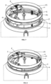
- the docking system 1 for spacecraft is shown in a stowed position in Fig. 1 and in a deployed position in Fig. 5 .
- the docking system 1 comprises an end ring 3 and a docking assembly 2.
- the docking assembly 2 comprises the following elements:
- the embodiment shown in the figures includes three docking platforms 5.
- Each docking platform 5 comprises:
- the support ring 4 and the end ring 3 are connected by elastic means 11 (in Figs. 6 and 7 the elastic means 11 are longitudinal springs), such that in a stowed position (see Fig. 1 ) the docking assembly 2 is placed inside the end ring 3 and in a deployed position (see Fig. 5 ) the docking assembly 2 is placed out of the end ring 3.
- the longitudinal springs can have one of its ends on a fixed element 22 in the end ring 3 (see Fig. 7 ).
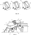
- the initial engagement means 9 can be latch mechanisms, as the ones shown in Figs. 7 , 9 and 15 . They can comprise a latch bracket 12, a spring and a latch 13 as a movable element.
- the docking platforms 5 can comprise an end stop and torque springs 14 with one pin 15 attached to the support ring 4 and one pin 15' attached to the main body 7 of the docking platform 5 (see Figs. 2 and 6 ).
- Fig. 16 As for the docking mechanism 10, it is represented in Fig. 16 and can comprise:
- the docking system 1 can be integrated in a spacecraft 20, such that one end of the linear actuators 6 is attached to the inner surface of the spacecraft 20, as seen in Figs. 3, 4 and 5 .
- the spacecraft 20 can be a satellite adapter in a launcher (see Figs. 10-14 ), and also a satellite with an interface ring.
- the satellite adapter can be equipped with the launcher last stage 21 that performs the control and guidance functions.
- This docking system 1 is especially applicable to a satellite adapter in a launcher.
- the last stage of the launcher places the payload (a customer satellite, for example) in the geostationary orbit.
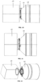
- Fig. 10 shows the satellite adapter 20, the last stage 21, the customer satellite 23 and the docking system 1 for spacecraft before the satellite separation.
- Fig. 11 shows the separation of the customer satellite 23 from the satellite adapter 20.
- Fig. 12 shows the deployment of the docking assembly 2 after the separation of the customer satellite 23 from the satellite adapter 20.
- the rendezvous When the separation of the customer satellite 23 from the satellite adapter 20 and the deployment of the docking assembly 2 have finished, the first phase of the mission for life extension of the satellite adapter starts (it is called the rendezvous).
- Fig. 13 shows the approximation of the satellite adapter 20 to the target satellite 24. It can be seen that the target satellite 24 is completely deployed. The target satellite 24 has an interface ring 25 that remains in it after the separation when it was launched into orbit, and there is no need for any special adaptations in the interface ring 25 for performing the docking.
- Fig. 14 shows the docking between the target satellite 24 and the satellite adapter 20.
- the satellite adapter 20 could give support to the target satellite 24, for example in orbit and attitude maneuvers, navigation, communication, etc.
- the docking assembly 2 is stowed, as it needs to be integrated inside the internal volume of the satellite adapter 20 (see Fig. 1 ).
- the first phase of the docking is the deployment of the docking assembly 2, shown in Figs. 1 to 4 .
- the joint element can also be an electrovalve.
- the joint between the docking platforms 5 and the satellite adapter 20 is cut-off, so the docking platforms 5 do not have the opposition of the joint and the torque springs 14 attached to the docking platforms 5 make them rotate.
- Fig. 2 the configuration of these torque springs 14 can be seen.
- this Fig. 2 there are two torque springs 14 attached to each docking platform 5, one at each end.
- the aim of the torque springs 14 is to apply a torque to the articulation that joins the docking platform 5 with the support ring 4, so one pin 15 needs to be fixed to the docking platform 5 and the other pin 15' needs to be fixed to the support ring 4.
- the docking platforms 5 start rotating.
- the docking platforms 5 rotate due to the action of the torque springs 14 until the lower surface of the main body 7 of the docking platforms 5 touches the upper surface of the support ring 4.
- a latch mechanism 9 can be introduced in the articulation between the docking platform 5 and the support ring 4, such that when the docking platform 5 touches the support ring 4, the latch 13 can be activated by a spring.
- Fig. 5 shows the position in which the support ring 4 is displaced vertically to achieve a gap between the docking assembly 2 and the upper surface of the satellite adapter 20. The aim of this gap is to protect the satellite adapter 20 and the target satellite 24 when the contact between them takes place. The shock energy is absorbed by the support ring 4.
- longitudinal springs 11 for instance, three ones, in Fig. 7 ) are arranged, fixed to the end ring 3 of the satellite adapter 20 on one end and to the support ring 4 on the other end.
- the longitudinal springs 11 are positioned around the support ring 4 circumference with the same angular distance between each other.
- the longitudinal springs 11 are compressed and the support ring 4 is held by the linear actuators 6.
- the actuators 6 stop applying force and the longitudinal springs 11 are elongated, displacing the support ring 4 in the axial direction.
- a fix element 22 has been designed to serve as a platform to fix the longitudinal springs 11.
- the other end of the spring 11 is attached to the bottom surface of the support ring 4, as seen in Fig. 7 .
- the next phase starts with the approximation of the satellite adapter 20 to the target satellite 24.
- the guide members 8 of the docking platform 5 correct the misalignments of the docking, and the interface ring 25 of the target satellite 24 touches the upper surface of the main body 7 of the docking platform 5.
- the initial engagement means 9 are latches. After this initial engagement the target satellite 24 is partially constrained by the initial engagement means 9 (i.e., the latches in figures 7 , 9 and 15 ).
- the latch 13 is outspread from its support element before the approach of the target satellite 24.
- the position of the latch 13 is achieved using a spring attached both to the latch 13 and to the latch support. Then, when the interface ring 25 of the target satellite 24 touches the latch 13, the spring 11 is compressed and the latch 13 is inserted progressively in the latch support. The target satellite 24 will continue approaching the satellite adapter 20 and finally, the ring 25 of the target satellite 24 makes contact with the docking platform 5. At that instant, the ring 25 stops making contact with the latch 13 and the latch 13 rotates to its initial position pushed by the force of the spring (see the steps in Fig. 15 ). Finally the latch 13 presses the inner flange of the interface ring 25 of the target satellite 24.
- the soft docking phase finishes.
- the satellite adapter 20 and the target satellite 24 are prevented from axial relative displacement between them. Then, the shock produced by the contact will compress the longitudinal springs 11 and will retract the support ring 4 until the maximum compression of the springs 11 is achieved. After that, the springs 11 will apply the same compression force in the opposite direction to the support ring 4 and an oscillatory movement between them will take place.
- This oscillatory movement is attenuated by the pull and push forces that the linear actuators 6 will apply, so, after some time, the relative movement between the satellite adapter 20 and the target satellite 24 will stop.
- This phase is performed by retracting the support ring 4 until it reaches its initial position (see Fig. 8 ).
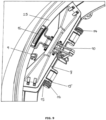
- the pressure member 16 of the docking mechanism 10 rotates, applying a force on the inner flange of the interface ring 25 of the target satellite 24 ( Figs. 8 and 9 ), thus completing the docking.
- This docking mechanism 10 is not only fixed to the docking platform 5, but is also articulated to the end ring 3 in the satellite adapter 20.
- the docking mechanism 10 makes the pressure member 16 (for instance, in the shape of a bridle) open.
- the pressure member 16 is moved in the opposite way, that is, the pressure member 16 closes. In this way, when the support ring 4 reaches its final position, the pressure member 16 applies the maximum force on the inner flange of the interface ring 25 of the target satellite 24 necessary to achieve a rigid docking.
- Figure 9 shows the configuration of the docking mechanism 10 in its final position.
- the actuators 6 retract the support ring 4, the springs 11 attached to this support ring 4 will compress. In this way, the actuators 6 will be placed in a configuration of continuous attraction in order to ensure the hard docking during the mission.
Landscapes
- Engineering & Computer Science (AREA)
- Remote Sensing (AREA)
- Aviation & Aerospace Engineering (AREA)
- Control Of Position, Course, Altitude, Or Attitude Of Moving Bodies (AREA)
- Motorcycle And Bicycle Frame (AREA)
Claims (10)
- Andocksystem (1) für Raumfahrzeuge, das einen Endring (3) und eine Andockbaugruppe (2) umfasst, wobei die Andockbaugruppe (2) einen Stützring (4) umfasst, der mit einer Vielzahl von Linearaktuatoren (6) zum Ausfahren und Einfahren verbunden ist, wobei der Stützring (4) und der Endring (3) so verbunden sind, dass die Andockbaugruppe (2) in einer verstauten Position in den Endring (3) eingesetzt ist und in einer ausgefahrenen Position die Andockbaugruppe (2) außerhalb des Endrings (3) positioniert ist,dadurch gekennzeichnet, dass die Andockbaugruppe mindestens drei Andockplattformen (5) umfasst, die an dem Stützring (4) angelenkt sind, wobei jede Andockplattform (5) Folgendes umfasst:- einen Hauptkörper (7),- ein Führungselement (8),- anfängliche Eingriffsmittel (9), und- einen Andockmechanismus (10), der an dem Hauptkörper (7) befestigt und an dem Endring (3) angelenkt ist,der Stützring (4) und der Endring (3) durch elastische Mittel (11) verbunden sind.
- Andocksystem (1) für Raumfahrzeuge nach Anspruch 1, wobei die elastischen Mittel (11) Längsfedern mit einem Ende an einem festen Element (22) im Endring (3) sind.
- Andocksystem (1) für Raumfahrzeuge nach einem der vorstehenden Ansprüche, wobei die anfänglichen Eingriffsmittel (9) Verriegelungsmechanismen sind
- Andocksystem (1) für Raumfahrzeuge nach Anspruch 3, wobei die Verriegelungsmechanismen eine Verriegelungshalterung (12), eine Feder und eine Verriegelung (13) als bewegliches Element umfassen.
- Andocksystem (1) für Raumfahrzeuge nach einem der vorstehenden Ansprüche, wobei die Andockplattformen (5) jeweils eine Anschlag- und Drehmomentfeder (14) mit einem Stift (15), der am Stützring (4) befestigt ist, und einem Stift (15'), der am Hauptkörper (7) der Andockplattform (5) befestigt ist, umfassen.
- Andocksystem (1) für Raumfahrzeuge nach einem der vorstehenden Ansprüche, wobei der Andockmechanismus (10) Folgendes umfasst:- ein Druckelement (16),- eine Halterung (17), die am Hauptkörper (7) der Andockplattform (5) befestigt ist,- vier Gelenkverbindungen (18), und- ein Befestigungselement (19), das in den Endring (3) integriert ist und das Ende eines der Glieder mit dem Endring (3) gelenkig verbindet.
- Raumfahrzeug (20) mit einem Andocksystem (1) für Raumfahrzeuge, dadurch gekennzeichnet, dass es ein Andocksystem (1) für Raumfahrzeuge nach den Ansprüchen 1 bis 6 an einem Ende umfasst, so dass ein Ende der Linearaktuatoren (6) an einer Innenfläche des Raumfahrzeugs (20) befestigt ist.
- Raumfahrzeug (20) mit einem Andocksystem (1) für Raumfahrzeuge nach Anspruch 7, wobei das Raumfahrzeug (20) ein Satellitenadapter in einer Trägerrakete ist.
- Raumfahrzeug (20) mit einem Andocksystem (1) für Raumfahrzeuge nach Anspruch 7, wobei das Raumfahrzeug (20) ein Satellit mit einem Schnittstellenring ist.
- Raumfahrzeug (20) mit einem Andocksystem (1) für Raumfahrzeuge nach Anspruch 8, wobei der Satellitenadapter mit der letzten Stufe (21) der Trägerrakete ausgestattet ist, die die Steuerungs- und Führungsfunktionen ausführt.
Applications Claiming Priority (1)
| Application Number | Priority Date | Filing Date | Title |
|---|---|---|---|
| PCT/ES2021/070199 WO2022195137A1 (es) | 2021-03-18 | 2021-03-18 | Sistema de acoplamiento para vehículos espaciales y vehículo espacial que lo comprende |
Publications (3)
| Publication Number | Publication Date |
|---|---|
| EP4310009A1 EP4310009A1 (de) | 2024-01-24 |
| EP4310009C0 EP4310009C0 (de) | 2024-12-18 |
| EP4310009B1 true EP4310009B1 (de) | 2024-12-18 |
Family
ID=75497959
Family Applications (1)
| Application Number | Title | Priority Date | Filing Date |
|---|---|---|---|
| EP21718631.1A Active EP4310009B1 (de) | 2021-03-18 | 2021-03-18 | Andocksystem für raumfahrzeug und raumfahrzeug damit |
Country Status (3)
| Country | Link |
|---|---|
| EP (1) | EP4310009B1 (de) |
| ES (1) | ES3014519T3 (de) |
| WO (1) | WO2022195137A1 (de) |
Families Citing this family (1)
| Publication number | Priority date | Publication date | Assignee | Title |
|---|---|---|---|---|
| CN118618640A (zh) * | 2024-04-30 | 2024-09-10 | 哈尔滨工业大学 | 一种非杆锥式的模块化立方星电磁对接机构 |
Family Cites Families (4)
| Publication number | Priority date | Publication date | Assignee | Title |
|---|---|---|---|---|
| US5040749A (en) * | 1989-02-22 | 1991-08-20 | Space Industries, Inc. | Spacecraft berthing mechanism with discrete impact attennation means |
| US6354540B1 (en) * | 1998-09-29 | 2002-03-12 | The United States Of America As Represented By The Administrator Of The National Aeronautics And Space Administration | Androgynous, reconfigurable closed loop feedback controlled low impact docking system with load sensing electromagnetic capture ring |
| CN103926936B (zh) * | 2014-03-25 | 2016-04-20 | 哈尔滨工业大学 | 一种用于纵向运动模拟的六自由度并联组装机构 |
| CN104477417B (zh) | 2014-09-19 | 2016-08-24 | 航天东方红卫星有限公司 | 一种星星在轨对接及锁定装置 |
-
2021
- 2021-03-18 WO PCT/ES2021/070199 patent/WO2022195137A1/es not_active Ceased
- 2021-03-18 ES ES21718631T patent/ES3014519T3/es active Active
- 2021-03-18 EP EP21718631.1A patent/EP4310009B1/de active Active
Also Published As
| Publication number | Publication date |
|---|---|
| WO2022195137A1 (es) | 2022-09-22 |
| EP4310009A1 (de) | 2024-01-24 |
| EP4310009C0 (de) | 2024-12-18 |
| ES3014519T3 (en) | 2025-04-23 |
Similar Documents
| Publication | Publication Date | Title |
|---|---|---|
| RU2155146C2 (ru) | Наклонный адаптер для транспортирования нескольких полезных нагрузок на одной ракете-носителе | |
| CN110914157B (zh) | 用于捕获客户飞行器的系统和相关方法 | |
| US5040749A (en) | Spacecraft berthing mechanism with discrete impact attennation means | |
| EP4237338A1 (de) | Erfassungssystem zur erfassung von raumobjekten, insbesondere zur rückgewinnung oder deorbitierung | |
| WO1986001484A1 (en) | Satelite transfer vehicle | |
| US4326684A (en) | Spacecraft with internal propulsion stages | |
| UA128746C2 (uk) | Пристрій множинного утримування та відділення для космічного апарата та способи відділення космічного апарата з вивідного пристрою ракети-носія та встановлення пристрою множинного утримування та відділення для космічного апарата | |
| US20240228070A1 (en) | Rotary-ring separation device and method | |
| EP4310009B1 (de) | Andocksystem für raumfahrzeug und raumfahrzeug damit | |
| DE69532522T3 (de) | Verfahren und vorrichtung für das arbeiten von satelliten im weltraum | |
| US10214303B1 (en) | Low cost launch vehicle fairing | |
| US20170260929A1 (en) | Device and locking of a fueling device | |
| US4324374A (en) | Integrated spacecraft and cradle structure | |
| JP7270461B2 (ja) | 電気機械的点分離システム | |
| US4300737A (en) | Satellite deployment system with remotely controlled relocking capability | |
| US12378010B2 (en) | Vehicle capture assemblies and related devices, systems, and methods | |
| US4213586A (en) | Spin activated safety circuit for spacecraft | |
| US4290570A (en) | Three point attachment for an ejectable spacecraft | |
| US4303214A (en) | Apparatus for gyroscopic ejection of shuttle launched spacecraft | |
| EP3438003A1 (de) | Multireflektorniederhalteanordnung | |
| EP4588811A1 (de) | System zur befestigung und trennung von strukturen | |
| EP4667364A1 (de) | Verschlussanordnung eines hitzeschildes eines luft- und raumfahrzeuges mit direktionaler bremsfunktion während der sinkphase | |
| US11964781B2 (en) | Coupling unit for detachable coupling parts of a spacecraft | |
| Qureshi et al. | Cutting the Cost of a Star Shade Occulter Using In-Space Assembly | |
| Fosness et al. | Overview of spacecraft deployment and release devices efforts at the Air Force Research Laboratory |
Legal Events
| Date | Code | Title | Description |
|---|---|---|---|
| STAA | Information on the status of an ep patent application or granted ep patent |
Free format text: STATUS: UNKNOWN |
|
| STAA | Information on the status of an ep patent application or granted ep patent |
Free format text: STATUS: THE INTERNATIONAL PUBLICATION HAS BEEN MADE |
|
| PUAI | Public reference made under article 153(3) epc to a published international application that has entered the european phase |
Free format text: ORIGINAL CODE: 0009012 |
|
| STAA | Information on the status of an ep patent application or granted ep patent |
Free format text: STATUS: REQUEST FOR EXAMINATION WAS MADE |
|
| 17P | Request for examination filed |
Effective date: 20231017 |
|
| AK | Designated contracting states |
Kind code of ref document: A1 Designated state(s): AL AT BE BG CH CY CZ DE DK EE ES FI FR GB GR HR HU IE IS IT LI LT LU LV MC MK MT NL NO PL PT RO RS SE SI SK SM TR |
|
| DAV | Request for validation of the european patent (deleted) | ||
| DAX | Request for extension of the european patent (deleted) | ||
| GRAP | Despatch of communication of intention to grant a patent |
Free format text: ORIGINAL CODE: EPIDOSNIGR1 |
|
| STAA | Information on the status of an ep patent application or granted ep patent |
Free format text: STATUS: GRANT OF PATENT IS INTENDED |
|
| INTG | Intention to grant announced |
Effective date: 20240827 |
|
| GRAS | Grant fee paid |
Free format text: ORIGINAL CODE: EPIDOSNIGR3 |
|
| GRAA | (expected) grant |
Free format text: ORIGINAL CODE: 0009210 |
|
| STAA | Information on the status of an ep patent application or granted ep patent |
Free format text: STATUS: THE PATENT HAS BEEN GRANTED |
|
| RAP3 | Party data changed (applicant data changed or rights of an application transferred) |
Owner name: AIRBUS DEFENCE AND SPACE, S.A. |
|
| AK | Designated contracting states |
Kind code of ref document: B1 Designated state(s): AL AT BE BG CH CY CZ DE DK EE ES FI FR GB GR HR HU IE IS IT LI LT LU LV MC MK MT NL NO PL PT RO RS SE SI SK SM TR |
|
| REG | Reference to a national code |
Ref country code: CH Ref legal event code: EP |
|
| REG | Reference to a national code |
Ref country code: DE Ref legal event code: R096 Ref document number: 602021023557 Country of ref document: DE |
|
| REG | Reference to a national code |
Ref country code: IE Ref legal event code: FG4D |
|
| U01 | Request for unitary effect filed |
Effective date: 20250109 |
|
| U07 | Unitary effect registered |
Designated state(s): AT BE BG DE DK EE FI FR IT LT LU LV MT NL PT RO SE SI Effective date: 20250114 |
|
| PG25 | Lapsed in a contracting state [announced via postgrant information from national office to epo] |
Ref country code: HR Free format text: LAPSE BECAUSE OF FAILURE TO SUBMIT A TRANSLATION OF THE DESCRIPTION OR TO PAY THE FEE WITHIN THE PRESCRIBED TIME-LIMIT Effective date: 20241218 |
|
| PG25 | Lapsed in a contracting state [announced via postgrant information from national office to epo] |
Ref country code: NO Free format text: LAPSE BECAUSE OF FAILURE TO SUBMIT A TRANSLATION OF THE DESCRIPTION OR TO PAY THE FEE WITHIN THE PRESCRIBED TIME-LIMIT Effective date: 20250318 |
|
| REG | Reference to a national code |
Ref country code: ES Ref legal event code: FG2A Ref document number: 3014519 Country of ref document: ES Kind code of ref document: T3 Effective date: 20250423 |
|
| PG25 | Lapsed in a contracting state [announced via postgrant information from national office to epo] |
Ref country code: GR Free format text: LAPSE BECAUSE OF FAILURE TO SUBMIT A TRANSLATION OF THE DESCRIPTION OR TO PAY THE FEE WITHIN THE PRESCRIBED TIME-LIMIT Effective date: 20250319 |
|
| PG25 | Lapsed in a contracting state [announced via postgrant information from national office to epo] |
Ref country code: RS Free format text: LAPSE BECAUSE OF FAILURE TO SUBMIT A TRANSLATION OF THE DESCRIPTION OR TO PAY THE FEE WITHIN THE PRESCRIBED TIME-LIMIT Effective date: 20250318 |
|
| U20 | Renewal fee for the european patent with unitary effect paid |
Year of fee payment: 5 Effective date: 20250325 |
|
| PG25 | Lapsed in a contracting state [announced via postgrant information from national office to epo] |
Ref country code: SM Free format text: LAPSE BECAUSE OF FAILURE TO SUBMIT A TRANSLATION OF THE DESCRIPTION OR TO PAY THE FEE WITHIN THE PRESCRIBED TIME-LIMIT Effective date: 20241218 |
|
| PG25 | Lapsed in a contracting state [announced via postgrant information from national office to epo] |
Ref country code: PL Free format text: LAPSE BECAUSE OF FAILURE TO SUBMIT A TRANSLATION OF THE DESCRIPTION OR TO PAY THE FEE WITHIN THE PRESCRIBED TIME-LIMIT Effective date: 20241218 |
|
| PGFP | Annual fee paid to national office [announced via postgrant information from national office to epo] |
Ref country code: ES Payment date: 20250429 Year of fee payment: 5 |
|
| PG25 | Lapsed in a contracting state [announced via postgrant information from national office to epo] |
Ref country code: IS Free format text: LAPSE BECAUSE OF FAILURE TO SUBMIT A TRANSLATION OF THE DESCRIPTION OR TO PAY THE FEE WITHIN THE PRESCRIBED TIME-LIMIT Effective date: 20250418 |
|
| PG25 | Lapsed in a contracting state [announced via postgrant information from national office to epo] |
Ref country code: SK Free format text: LAPSE BECAUSE OF FAILURE TO SUBMIT A TRANSLATION OF THE DESCRIPTION OR TO PAY THE FEE WITHIN THE PRESCRIBED TIME-LIMIT Effective date: 20241218 |
|
| PG25 | Lapsed in a contracting state [announced via postgrant information from national office to epo] |
Ref country code: CZ Free format text: LAPSE BECAUSE OF FAILURE TO SUBMIT A TRANSLATION OF THE DESCRIPTION OR TO PAY THE FEE WITHIN THE PRESCRIBED TIME-LIMIT Effective date: 20241218 |
|
| PG25 | Lapsed in a contracting state [announced via postgrant information from national office to epo] |
Ref country code: MC Free format text: LAPSE BECAUSE OF FAILURE TO SUBMIT A TRANSLATION OF THE DESCRIPTION OR TO PAY THE FEE WITHIN THE PRESCRIBED TIME-LIMIT Effective date: 20241218 |
|
| PLBE | No opposition filed within time limit |
Free format text: ORIGINAL CODE: 0009261 |
|
| REG | Reference to a national code |
Ref country code: CH Ref legal event code: H13 Free format text: ST27 STATUS EVENT CODE: U-0-0-H10-H13 (AS PROVIDED BY THE NATIONAL OFFICE) Effective date: 20251023 |
|
| STAA | Information on the status of an ep patent application or granted ep patent |
Free format text: STATUS: NO OPPOSITION FILED WITHIN TIME LIMIT |
|
| 26N | No opposition filed |
Effective date: 20250919 |
|
| PG25 | Lapsed in a contracting state [announced via postgrant information from national office to epo] |
Ref country code: CH Free format text: LAPSE BECAUSE OF NON-PAYMENT OF DUE FEES Effective date: 20250331 |
|
| PG25 | Lapsed in a contracting state [announced via postgrant information from national office to epo] |
Ref country code: IE Free format text: LAPSE BECAUSE OF NON-PAYMENT OF DUE FEES Effective date: 20250318 |
|
| PGFP | Annual fee paid to national office [announced via postgrant information from national office to epo] |
Ref country code: GB Payment date: 20260324 Year of fee payment: 6 |
|
| U20 | Renewal fee for the european patent with unitary effect paid |
Year of fee payment: 6 Effective date: 20260326 |