EP4310005A1 - Ensemble propulsif à hélice pour aéronef - Google Patents
Ensemble propulsif à hélice pour aéronef Download PDFInfo
- Publication number
- EP4310005A1 EP4310005A1 EP23186125.3A EP23186125A EP4310005A1 EP 4310005 A1 EP4310005 A1 EP 4310005A1 EP 23186125 A EP23186125 A EP 23186125A EP 4310005 A1 EP4310005 A1 EP 4310005A1
- Authority
- EP
- European Patent Office
- Prior art keywords
- plate
- propulsion assembly
- propulsion
- fixing
- fixing means
- Prior art date
- Legal status (The legal status is an assumption and is not a legal conclusion. Google has not performed a legal analysis and makes no representation as to the accuracy of the status listed.)
- Granted
Links
Images



Classifications
-
- B—PERFORMING OPERATIONS; TRANSPORTING
- B64—AIRCRAFT; AVIATION; COSMONAUTICS
- B64D—EQUIPMENT FOR FITTING IN OR TO AIRCRAFT; FLIGHT SUITS; PARACHUTES; ARRANGEMENT OR MOUNTING OF POWER PLANTS OR PROPULSION TRANSMISSIONS IN AIRCRAFT
- B64D27/00—Arrangement or mounting of power plants in aircraft; Aircraft characterised by the type or position of power plants
- B64D27/02—Aircraft characterised by the type or position of power plants
- B64D27/24—Aircraft characterised by the type or position of power plants using steam or spring force
-
- B—PERFORMING OPERATIONS; TRANSPORTING
- B64—AIRCRAFT; AVIATION; COSMONAUTICS
- B64D—EQUIPMENT FOR FITTING IN OR TO AIRCRAFT; FLIGHT SUITS; PARACHUTES; ARRANGEMENT OR MOUNTING OF POWER PLANTS OR PROPULSION TRANSMISSIONS IN AIRCRAFT
- B64D27/00—Arrangement or mounting of power plants in aircraft; Aircraft characterised by the type or position of power plants
- B64D27/40—Arrangements for mounting power plants in aircraft
- B64D27/402—Arrangements for mounting power plants in aircraft comprising box like supporting frames, e.g. pylons or arrangements for embracing the power plant
-
- B—PERFORMING OPERATIONS; TRANSPORTING
- B64—AIRCRAFT; AVIATION; COSMONAUTICS
- B64C—AEROPLANES; HELICOPTERS
- B64C11/00—Propellers, e.g. of ducted type; Features common to propellers and rotors for rotorcraft
-
- B—PERFORMING OPERATIONS; TRANSPORTING
- B64—AIRCRAFT; AVIATION; COSMONAUTICS
- B64D—EQUIPMENT FOR FITTING IN OR TO AIRCRAFT; FLIGHT SUITS; PARACHUTES; ARRANGEMENT OR MOUNTING OF POWER PLANTS OR PROPULSION TRANSMISSIONS IN AIRCRAFT
- B64D27/00—Arrangement or mounting of power plants in aircraft; Aircraft characterised by the type or position of power plants
- B64D27/02—Aircraft characterised by the type or position of power plants
- B64D27/30—Aircraft characterised by electric power plants
-
- B—PERFORMING OPERATIONS; TRANSPORTING
- B64—AIRCRAFT; AVIATION; COSMONAUTICS
- B64D—EQUIPMENT FOR FITTING IN OR TO AIRCRAFT; FLIGHT SUITS; PARACHUTES; ARRANGEMENT OR MOUNTING OF POWER PLANTS OR PROPULSION TRANSMISSIONS IN AIRCRAFT
- B64D27/00—Arrangement or mounting of power plants in aircraft; Aircraft characterised by the type or position of power plants
- B64D27/02—Aircraft characterised by the type or position of power plants
- B64D27/30—Aircraft characterised by electric power plants
- B64D27/34—All-electric aircraft
-
- B—PERFORMING OPERATIONS; TRANSPORTING
- B64—AIRCRAFT; AVIATION; COSMONAUTICS
- B64D—EQUIPMENT FOR FITTING IN OR TO AIRCRAFT; FLIGHT SUITS; PARACHUTES; ARRANGEMENT OR MOUNTING OF POWER PLANTS OR PROPULSION TRANSMISSIONS IN AIRCRAFT
- B64D27/00—Arrangement or mounting of power plants in aircraft; Aircraft characterised by the type or position of power plants
- B64D27/02—Aircraft characterised by the type or position of power plants
- B64D27/30—Aircraft characterised by electric power plants
- B64D27/35—Arrangements for on-board electric energy production, distribution, recovery or storage
- B64D27/355—Arrangements for on-board electric energy production, distribution, recovery or storage using fuel cells
-
- B—PERFORMING OPERATIONS; TRANSPORTING
- B64—AIRCRAFT; AVIATION; COSMONAUTICS
- B64D—EQUIPMENT FOR FITTING IN OR TO AIRCRAFT; FLIGHT SUITS; PARACHUTES; ARRANGEMENT OR MOUNTING OF POWER PLANTS OR PROPULSION TRANSMISSIONS IN AIRCRAFT
- B64D29/00—Power-plant nacelles, fairings or cowlings
- B64D29/02—Power-plant nacelles, fairings or cowlings associated with wings
-
- H—ELECTRICITY
- H01—ELECTRIC ELEMENTS
- H01M—PROCESSES OR MEANS, e.g. BATTERIES, FOR THE DIRECT CONVERSION OF CHEMICAL ENERGY INTO ELECTRICAL ENERGY
- H01M8/00—Fuel cells; Manufacture thereof
- H01M8/24—Grouping of fuel cells, e.g. stacking of fuel cells
- H01M8/2465—Details of groupings of fuel cells
-
- B—PERFORMING OPERATIONS; TRANSPORTING
- B64—AIRCRAFT; AVIATION; COSMONAUTICS
- B64D—EQUIPMENT FOR FITTING IN OR TO AIRCRAFT; FLIGHT SUITS; PARACHUTES; ARRANGEMENT OR MOUNTING OF POWER PLANTS OR PROPULSION TRANSMISSIONS IN AIRCRAFT
- B64D41/00—Power installations for auxiliary purposes
- B64D2041/005—Fuel cells
-
- H—ELECTRICITY
- H01—ELECTRIC ELEMENTS
- H01M—PROCESSES OR MEANS, e.g. BATTERIES, FOR THE DIRECT CONVERSION OF CHEMICAL ENERGY INTO ELECTRICAL ENERGY
- H01M2250/00—Fuel cells for particular applications; Specific features of fuel cell system
- H01M2250/20—Fuel cells in motive systems, e.g. vehicle, ship, plane
-
- Y—GENERAL TAGGING OF NEW TECHNOLOGICAL DEVELOPMENTS; GENERAL TAGGING OF CROSS-SECTIONAL TECHNOLOGIES SPANNING OVER SEVERAL SECTIONS OF THE IPC; TECHNICAL SUBJECTS COVERED BY FORMER USPC CROSS-REFERENCE ART COLLECTIONS [XRACs] AND DIGESTS
- Y02—TECHNOLOGIES OR APPLICATIONS FOR MITIGATION OR ADAPTATION AGAINST CLIMATE CHANGE
- Y02T—CLIMATE CHANGE MITIGATION TECHNOLOGIES RELATED TO TRANSPORTATION
- Y02T90/00—Enabling technologies or technologies with a potential or indirect contribution to GHG emissions mitigation
- Y02T90/40—Application of hydrogen technology to transportation, e.g. using fuel cells
Definitions
- the present invention relates to a propeller propulsion assembly for an aircraft, said propulsion assembly comprising a chassis fixed to a structure of a wing of the aircraft and a propulsion system consisting of at least one plate carrying at least one piece of equipment where the chassis has an opening in the lower part and where the tray is fixed to the chassis through said opening.
- the invention also relates to an aircraft comprising at least one such propulsion assembly.
- an aircraft conventionally comprises at least one propulsion assembly comprising a propulsion system arranged in a nacelle.
- the propulsion system comprises a frame, a motor attached to the frame and a propeller rotated by the motor.
- the chassis of the nacelle is fixed under a mast which is itself fixed under a wing structure of the aircraft.
- the propulsion system and more particularly the engine, comprises numerous elements which are fixed either to the mast or to the chassis and these elements are generally nested in a complex manner inside the chassis.
- the dismantling of the elements can be complex due to the fact that the elements to be checked can be fixed behind other elements which must be dismantled before accessing the elements to be checked.
- An object of the present invention is to propose a propulsion assembly which allows easy disassembly and reassembly of the elements constituting the propulsion system.
- the frame comprises a plurality of arches arranged one after the other and, between two successive arches, beams fixed by their ends to the two successive arches, where each arch is open downwards, and where for two arches successively, the two lower port ends of the two arches are connected by a lower beam and the two lower starboard ends of the two arches are connected by another lower beam.
- the fixing means takes the form of a stirrup with two legs, each pierced with a bore and secured to the plate, a tongue secured to the chassis and which has a spherical bore in which a sphere itself is housed crossed by a bore, and a bolt whose threaded rod passes through each bore.
- the fixing means takes the form of a first tongue pierced with a bore and secured to the plate, a second tongue pierced with a bore and secured to the chassis, a block made of a flexible material, two threaded rods secured to said block and arranged coaxially with respect to each other on either side of the block and for each threaded rod, a nut which tightens against the corresponding tongue.
- the fixing means takes the form of a connecting rod with three fixing points where each fixing point allows rotation around an axis parallel to a transverse direction of the propulsion assembly where the connecting rod is fixed by two points of fixation. fixing to the plate and by a fixing point to the chassis.
- the fixing means takes the form of a connecting rod with three fixing points where each fixing point allows rotation around an axis parallel to a longitudinal direction of the propulsion assembly where the connecting rod is fixed by two points of fixation. fixing to the plate and by a fixing point to the chassis.
- said propulsion assembly comprises a nacelle made up of covers and the fixing means also ensure the fixing of the covers to the chassis.
- said propulsion assembly comprises additional fixing means which directly fix the covers to the plate.
- the plate is made up of several sub-plates arranged one behind the other along a longitudinal direction of the propulsion assembly and where each sub-plate is fixed to the chassis using fixing means.
- the electric motor with the propeller is carried by the most forward sub-plate.
- the invention also proposes an aircraft comprising at least one propulsion assembly according to one of the preceding variants.
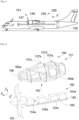
- FIG. 1 shows an aircraft 100 which has a fuselage 102 on either side of which is fixed a wing 104. Under each wing 104 is fixed at least one propulsion assembly 151 which comprises a nacelle 149 made up of covers 147 forming an aerodynamic exterior surface.
- Fig. 2 shows the propulsion assembly 151 without the nacelle 149 and which also includes a propulsion system 150 which is in exploded view.
- the propulsion assembly 151 has a longitudinal direction parallel to the longitudinal direction X of the aircraft 100, a transverse direction parallel to the transverse direction Y of the aircraft 100 and a vertical direction parallel to the vertical direction Z of the aircraft 100 .
- the propulsion system 150 comprises an electric motor 154a and a propeller 152 mounted on the shaft of the electric motor 154a and therefore rotated by said electric motor 154a.
- the axis of rotation of the propeller 152 is generally parallel to the longitudinal direction X.
- the propulsion assembly 151 also comprises a chassis 156 extending parallel to the longitudinal direction X and comprising structural elements connected together to form a cage.
- the chassis 156 constitutes a mast fixed to a structure of the wing 104 by fixing points 157a-d arranged in the upper part of the chassis 156 and which here are four in number.
- There is a rear fixing point 157a which is arranged at the rear of the chassis 156 and compensates for the forces in Z.
- There is a front fixing point 157b which is at the front of the rear fixing point 157a and which compensates for the forces Y.
- the structural elements of the chassis 156 comprise a plurality of arches 158, here five, arranged one after the other along the longitudinal direction successive 158 arches.
- Each arch 158 is open downwards.
- the two lower port ends of the two arches 158 are connected by a lower beam 160b and the two lower starboard ends of the two arches 158 are connected by another lower beam 160b.
- the lower beams 160b and the arches 158 define an opening 162 which is open downwards.
- the propulsion system 150 also includes a fuel cell 154b, a tank 154c containing dihydrogen, and a cooling system 154d.
- the propulsion system 150 may include other elements such as for example air supply systems, etc.
- the propulsion system 150 thus comprises the following propulsion elements: the electric motor 154a, the fuel cell 154b, the tank 154c and the cooling system 154d.
- the fuel cell 154b is supplied with air and hydrogen from the tank 154c to generate electricity which powers the electric motor 154a.
- the cooling system 154d is designed to cool the different elements of the propulsion system 150. These different elements 154a-d are known to those skilled in the art and are not described more precisely. The different cables, pipes, etc., which connect the different elements 154a-d together are not shown.
- the propulsion assembly 151 also comprises at least one plate 180 and on said or each plate at least one propulsion element 154a-d of the propulsion system 150 is fixed by any appropriate means such as screw elements, welds, etc.
- each plate 180 equipped with at least one propelling element 154a-d is placed in the chassis 156 from the bottom passing through the opening 162 and it is fixed to said chassis 156 by fixing means 182.
- Each fixing means 182 ensures the fixing of the plate 180 to an arch 158 or to a beam 160a-b.
- the fixing means 182 are distributed to port and starboard of the plate 180 and such an arrangement also makes it possible to structurally reinforce the chassis 156.
- the chassis 156 constitutes a cage which is hollow and has in the lower part an opening 162 through which the or each plate 180 equipped with at least one propelling element 154a-d is fixed, and it can therefore be introduced and removed during maintenance operations through said opening 162 and where the or each plate 180 closes the opening 162 when it is in place.
- each plate 180 equipped with at least one propelling element 154a-d performs an upward movement and, upon disassembly, it performs a downward movement.
- a single plate 180 which carries all the propulsion elements 154a-d of the propulsion system 150.
- FIG. 3 is a schematic representation of the first embodiment of the invention with a single plate 180 and where each fixing means 182 (seen here in dotted lines) is fixed between the plate 180 and the arches 158. In this embodiment, it There are four fixing means 182 on the port side and four on the starboard side distributed over the length of the plate 180.
- Each fixing means 182 can be a rigid system, such as for example a screw/nut system, connecting rods, but it can also be a flexible system.
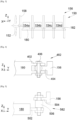
- Fig. 4 and the Fig. 5 show two particular embodiments of flexible systems which filter vibrations.
- the fixing means 482 takes the form of a stirrup 402 with two legs and secured to the plate 180 and a tongue 404 secured to the frame 156, that is to say an arch 158 or a beam 160a-b.
- the tongue 404 has a spherical bore in which is housed a sphere itself crossed by a bore.
- the tongue 404 is introduced into the stirrup 402 and the fixing means 482 also includes a bolt 406 which passes through each leg of the stirrup 402 through bores provided for this purpose and the sphere through the bore provided for this purpose.
- the threaded rod of the bolt 406 thus passes through each bore and the head of the screw and the nut rest against the legs of the stirrup 402.
- the presence of the sphere makes it possible to create a ball joint between the chassis 156 and the plate 180.
- the fixing means 482 ensure a recovery of the forces in X, Y and Z.
- the fixing means 582 takes the form of a first tongue 502 secured to the plate 180 and a second tongue 504 secured to the frame 156, that is to say an arch 158 or a beam 160a- b.
- the first tongue 502 and the second tongue 504 each have a bore and the fixing means 582 comprises a block 506 made of a flexible material such as rubber, and two threaded rods secured to said block 506 and arranged coaxially one by relative to each other on either side of the block 506.
- Each threaded rod is housed in one of the bores of the tongues 502 and 504 and receives a nut which tightens against the corresponding tongue 502, 504.
- the fixing means 582 ensure a recovery of the forces in X, Y and Z.
- FIG. 6 shows a second embodiment in which the plate 180 is fixed to the chassis 156 by two fixing means 182 at the front (one to port and one to starboard) and by two fixing means 682 to the rear (one to port and one to starboard).
- the fixing means 182 at the front can be rigid or flexible like those described in Figs. 4 and 5 and ensure a recovery of efforts in X, Y and Z.
- Each fixing means 682 at the rear takes the form of a connecting rod with three fixing points where each fixing point allows rotation around an axis parallel to the transverse direction of the propulsion assembly 151, i.e. i.e. horizontal and perpendicular to the longitudinal direction.
- the connecting rod is fixed by two fixing points to the plate 180 and by a fixing point to the chassis 156 here at the level of a beam 160a.
- Each fixing means 682 ensures a recovery of the forces in X and Z. Of course a reverse assembly is possible with two fixing points to the chassis 156 and one fixing point to the plate 180.
- FIG. 7 shows a third embodiment in which the plate 180 is fixed to the chassis 156 by two pairs of fixing means 182, a pair at the front and a pair at the rear and for each pair, a fixing means 182 on the port side and one to starboard.
- the fixing is completed by two fixing means 782 (one to port and one to starboard) between the pair at the front and the pair at the rear.
- the fixing means 182 at the front and rear can be rigid or flexible like those described in Figs. 4 and 5 and ensure a recovery of efforts in X, Y and Z.
- Each intermediate fixing means 782 takes the form of a connecting rod with three fixing points where each fixing point allows rotation around an axis parallel to the transverse direction of the propulsion assembly 151, that is to say horizontal and perpendicular to the longitudinal direction.
- the connecting rod is fixed by two fixing points to the plate 180 and by a fixing point to the chassis 156 here at the level of a beam 160a.
- Each fixing means 782 ensures a recovery of the forces in X and Z. Of course a reverse assembly is possible with two fixing points to the chassis 156 and one fixing point to the plate 180.
- FIG. 8 shows a fourth embodiment in which the plate 180 is fixed to the chassis 156 by two fixing means 182 at the front (one to port and one to starboard) and by one fixing means 882 to the rear.
- the fixing means 182 at the front can be rigid or flexible like those described in Figs. 4 and 5 and ensure a recovery of efforts in X, Y and Z.
- the fixing means 882 at the rear takes the form of a connecting rod with three fixing points where each fixing point allows rotation around an axis parallel to the longitudinal direction of the propulsion assembly 151.
- the connecting rod is fixed by two points of attachment to the plate 180 and by a point of attachment to the chassis 156.
- the fixing means 882 ensures a recovery of the forces in Y and Z.
- a reverse assembly is possible with two points of attachment to the chassis 156 and a point of attachment to the plate 180.
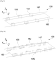
- the plate 180 is fixed to the chassis 156 represented here by the arches 158 by fixing means 182 which here take the form of rivets or screw elements like a screw/nut system and which simultaneously fix the plate 180 and the covers 147 from nacelle 149 to chassis 156.
- the plate 180 is thus housed inside the chassis 156 and the covers 147 are outside the chassis 156.
- the plate 180 and the covers 147 of the nacelle 149 are fixed to the chassis 156 represented here by the arches 158 by fixing means 182 which here take the form of rivets or screw elements such as a screw/nut system and which simultaneously fix the plate 180 and the covers 147 of the nacelle 149 to the chassis 156.
- the propulsion assembly 151 also includes additional fixing means 1082 which directly fix the covers 147 to the plate 180 and which also take the form of rivets or screw elements such as a screw/nut system.
- each plate 180 is made up of several sub-plates independent of each other for Figs. 11 and 12 and connected to each other for Fig. 13 .
- Each sub-platform is fixed to the chassis 156 by fixing means 182.
- the fixing means 182 shown are arranged in pairs with one fixing means 182 on the port side and one on the starboard side of each sub-platform, thus repeating the fixing means 482, 582 described in Figs. 4 and 5 , but each fixing means can have a different location and have a different shape and take other forms such as for example those described in Figs. 6 to 10 .
- the plate 180 consists of two sub-plates 1180a-b separated from each other and arranged one behind the other in the direction of the longitudinal direction. On each sub-plate 1180a-b is fixed at least one propulsion element 154a-d of the propulsion system 150.
- the plate 180 consists of four sub-plates 1280a-d separated from each other and arranged one behind the other in the direction of the longitudinal direction. On each sub-plate 1280a-d is fixed at least one propulsion element 154a-d of the propulsion system 150.
- the plate 180 consists of three sub-plates 1380a-c arranged one behind the other in the direction of the longitudinal direction. On each sub-plate 1380a-c is fixed at least one propulsion element 154a-d of the propulsion system 150.
- the sub-plate 1380a is separated from the other sub-plates 1380b-c while the two other sub-plates 1380c-d are linked to each other by a pivot connection 1302 with a vertical axis.
- the separation of the plate 180 into several sub-plates makes it possible, among other things, to separate the elements 154a-d generating the most vibrations from the other elements, in particular the sensitive elements.
- the element generating the most vibrations is the electric motor 154a with the propeller 152 and is carried by the most forward sub-plate.
Landscapes
- Engineering & Computer Science (AREA)
- Aviation & Aerospace Engineering (AREA)
- Life Sciences & Earth Sciences (AREA)
- Manufacturing & Machinery (AREA)
- Sustainable Development (AREA)
- Sustainable Energy (AREA)
- Chemical & Material Sciences (AREA)
- Chemical Kinetics & Catalysis (AREA)
- Electrochemistry (AREA)
- General Chemical & Material Sciences (AREA)
- Transmission Devices (AREA)
- Arrangement Or Mounting Of Propulsion Units For Vehicles (AREA)
Abstract
Description
- La présente invention concerne un ensemble propulsif à hélice pour un aéronef, ledit ensemble propulsif comprenant un châssis fixé à une structure d'une voilure de l'aéronef et un système de propulsion constitué d'au moins un plateau portant au moins un équipement où le châssis présente une ouverture en partie basse et où le plateau se fixe au châssis à travers ladite ouverture. L'invention concerne également un aéronef comportant au moins un tel ensemble propulsif.
- Afin de se déplacer, un aéronef comporte classiquement au moins un ensemble propulsif comprenant un système de propulsion arrangé dans une nacelle. Le système de propulsion comporte un châssis, un moteur fixé au châssis et une hélice entraînée en rotation par le moteur. Le châssis de la nacelle est fixé sous un mât qui est lui-même fixé sous une structure de la voilure de l'aéronef.
- Le système de propulsion, et plus particulièrement le moteur, comporte de nombreux éléments qui sont fixés soit au mât, soit au châssis et ces éléments sont généralement imbriqués de manière complexe à l'intérieur du châssis.
- Lors des opérations de maintenance de l'ensemble propulsif, le démontage des éléments peut être complexe du fait que les éléments à contrôler peuvent être fixés derrière d'autres éléments qui doivent être démontés avant d'accéder aux éléments à contrôler.
- Un objet de la présente invention est de proposer un ensemble propulsif qui permet un démontage et un remontage aisés des éléments constituant le système de propulsion.
- À cet effet, est proposé un ensemble propulsif pour un aéronef comportant :
- un châssis creux et présentant en partie basse une ouverture,
- un système de propulsion comportant les éléments propulsifs suivants : un moteur électrique sur l'arbre moteur duquel est montée une hélice, une pile à combustible qui alimente électriquement le moteur électrique, un réservoir qui alimente en dihydrogène la pile à combustible et un système de refroidissement, et
- au moins un plateau, où ledit ou chaque plateau est fixé audit châssis par des moyens de fixation et ferme ladite ouverture et où sur ledit ou chaque plateau est fixé au moins un élément propulsif du système de propulsion.
- Avec un tel arrangement, il est facile de démonter chaque plateau par le dessous du châssis lors des opérations de maintenance.
- Avantageusement, le châssis comporte une pluralité d'arches disposées les unes à la suite des autres et, entre deux arches successives, des poutres fixées par leurs extrémités aux deux arches successives, où chaque arche est ouverte vers le bas, et où pour deux arches successives, les deux extrémités inférieures bâbord des deux arches sont reliées par une poutre inférieure et les deux extrémités inférieures tribord des deux arches sont reliées par une autre poutre inférieure.
- Avantageusement, le moyen de fixation prend la forme d'un étrier à deux pattes, chacune percée d'un alésage et solidaire du plateau, d'une languette solidaire du châssis et qui présente un alésage sphérique dans lequel est logée une sphère elle-même traversée par un alésage, et d'un boulon dont la tige filetée traverse chaque alésage.
- Avantageusement, le moyen de fixation prend la forme d'une première languette percée d'un alésage et solidaire du plateau, d'une deuxième languette percée d'un alésage et solidaire du châssis, d'un bloc constitué d'un matériau souple, de deux tiges filetées solidaires dudit bloc et arrangées de manière coaxiale l'une par rapport à l'autre de part et d'autre du bloc et pour chaque tige filetée, d'un écrou qui se serre contre la languette correspondante.
- Avantageusement, le moyen de fixation prend la forme d'une bielle à trois points de fixation où chaque point de fixation autorise une rotation autour d'un axe parallèle à une direction transversale de l'ensemble propulsif où la bielle est fixée par deux points de fixation au plateau et par un point de fixation au châssis.
- Avantageusement, le moyen de fixation prend la forme d'une bielle à trois points de fixation où chaque point de fixation autorise une rotation autour d'un axe parallèle à une direction longitudinale de l'ensemble propulsif où la bielle est fixée par deux points de fixation au plateau et par un point de fixation au châssis.
- Avantageusement, ledit ensemble propulsif comporte une nacelle constituée de capots et les moyens de fixation assurent également la fixation des capots au châssis.
- Avantageusement, ledit ensemble propulsif comporte des moyens additionnels de fixation qui fixent directement les capots au plateau.
- Avantageusement, le plateau est constitué de plusieurs sous-plateaux disposés les uns derrière les autres le long d'une direction longitudinale de l'ensemble propulsif et où chaque sous-plateau est fixé au châssis à l'aide de moyens de fixation.
- Avantageusement, le moteur électrique avec l'hélice est porté par le sous-plateau le plus en avant.
- L'invention propose également un aéronef comportant au moins un ensemble propulsif selon l'une des variantes précédentes.
- Les caractéristiques de l'invention mentionnées ci-dessus, ainsi que d'autres, apparaîtront plus clairement à la lecture de la description suivante d'un exemple de réalisation, ladite description étant faite en relation avec les dessins joints, parmi lesquels :
-
Fig. 1 est une vue de côté d'un aéronef comportant un ensemble propulsif selon l'invention, -
Fig. 2 est une vue éclatée et en perspective d'un ensemble propulsif selon l'invention, -
Fig. 3 est une représentation schématique vue de côté d'un ensemble propulsif selon un premier mode de réalisation de l'invention avec un plateau selon une première variante de l'invention, -
Fig. 4 est une vue en coupe d'un système de fixation selon une première variante de réalisation de l'invention, -
Fig. 5 est une vue en coupe d'un système de fixation selon une deuxième variante de réalisation de l'invention, -
Fig. 6 est une représentation schématique vue de côté d'un ensemble propulsif selon un deuxième mode de réalisation de l'invention, -
Fig. 7 est une représentation schématique vue de côté d'un ensemble propulsif selon un troisième mode de réalisation de l'invention, -
Fig. 8 est une représentation schématique vue de côté d'un ensemble propulsif selon un quatrième mode de réalisation de l'invention, -
Fig. 9 est une représentation schématique d'une vue en coupe par un plan horizontal de l'ensemble propulsif selon une variante de l'invention, -
Fig. 10 est une représentation schématique d'une vue en coupe par un plan horizontal de l'ensemble propulsif selon une autre variante de l'invention, -
Fig. 11 est une représentation schématique d'un plateau selon une deuxième variante de l'invention, -
Fig. 12 est une représentation schématique d'un plateau selon une troisième variante de l'invention, et -
Fig. 13 est une représentation schématique d'un plateau selon une quatrième variante de l'invention. - Dans la description qui suit, les termes relatifs à une position sont pris en référence à un aéronef en position d'avancement, c'est-à-dire comme il est représenté sur la
Fig. 1 où la flèche F montre la direction d'avancement de l'aéronef. - Dans la description qui suit, et par convention, on appelle X la direction longitudinale qui correspond à l'axe de l'aéronef orienté positivement vers l'avant dans le sens d'avancement de l'aéronef, on appelle Y la direction transversale qui est horizontale lorsque l'aéronef est au sol, et Z la direction verticale ou hauteur verticale lorsque l'aéronef est au sol, ces trois directions X, Y et Z étant orthogonales entre elles.
- La
Fig. 1 montre un aéronef 100 qui présente un fuselage 102 de part et d'autre duquel est fixée une aile 104. Sous chaque aile 104 est fixé au moins un ensemble propulsif 151 qui comporte une nacelle 149 constituée de capots 147 formant une surface extérieure aérodynamique. - La
Fig. 2 montre l'ensemble propulsif 151 sans la nacelle 149 et qui comporte également un système de propulsion 150 qui est en vue éclatée. L'ensemble propulsif 151 présente une direction longitudinale parallèle à la direction longitudinale X de l'aéronef 100, une direction transversale parallèle à la direction transversale Y de l'aéronef 100 et une direction verticale parallèle à la direction verticale Z de l'aéronef 100. - Le système de propulsion 150 comporte un moteur électrique 154a et une hélice 152 montée sur l'arbre du moteur électrique 154a et donc entraînée en rotation par ledit moteur électrique 154a. L'axe de rotation de l'hélice 152 est globalement parallèle à la direction longitudinale X.
- L'ensemble propulsif 151 comporte également un châssis 156 s'étendant parallèlement à la direction longitudinale X et comportant des éléments structurels reliés entre eux pour former une cage.
- Le châssis 156 constitue un mât fixé à une structure de l'aile 104 par des points de fixation 157a-d disposés en partie haute du châssis 156 et qui sont ici au nombre de quatre. Il y a un point de fixation arrière 157a qui est disposé à l'arrière du châssis 156 et compense les efforts en Z. Il y a un point de fixation avant 157b qui est à l'avant du point de fixation arrière 157a et qui compense les efforts Y. Il y a deux points de fixation latéraux 157c-d disposés de part et d'autre du point de fixation avant 157b et chacun compense les efforts en X et Z. Ces différents points de fixation ne font pas partie de l'invention et prennent toutes formes connues de l'homme du métier.
- Les éléments structurels du châssis 156 comportent une pluralité d'arches 158, ici cinq, disposées les unes à la suite des autres le long de la direction longitudinale X et entre deux arches 158 successives, des poutres 160a-b fixées par leurs extrémités aux deux arches 158 successives.
- Chaque arche 158 est ouverte vers le bas. Pour deux arches 158 successives, les deux extrémités inférieures bâbord des deux arches 158 sont reliées par une poutre inférieure 160b et les deux extrémités inférieures tribord des deux arches 158 sont reliées par une autre poutre inférieure 160b. Il n'y a pas de poutre qui relie une extrémité inférieure bâbord, respectivement tribord, d'une arche 158 à une extrémité inférieure tribord, respectivement tribord, de l'arche 158 suivante de manière à ne pas encombrer.
- Il y a d'autres poutres 160a qui relient les arches 158 entre elles, au-dessus des poutres inférieures 160b, de manière à former un espace confiné et creux à l'intérieur du châssis 156.
- Les poutres inférieures 160b et les arches 158 délimitent une ouverture 162 qui est ouverte vers le bas.
- Dans le cas d'un aéronef 100 utilisant une pile à combustible, le système de propulsion 150 comporte également une pile à combustible 154b, un réservoir 154c contenant du dihydrogène, et un système de refroidissement 154d. Selon le cas, le système de propulsion 150 peut comporter d'autres éléments comme par exemple des systèmes d'approvisionnement en air, ...
- Le système de propulsion 150 comporte ainsi les éléments propulsifs suivants : le moteur électrique 154a, la pile à combustible 154b, le réservoir 154c et le système de refroidissement 154d.
- Classiquement, la pile à combustible 154b est alimentée en air et en dihydrogène depuis le réservoir 154c pour générer de l'électricité qui alimente le moteur électrique 154a. Le système de refroidissement 154d est conçu pour refroidir les différents éléments du système de propulsion 150. Ces différents éléments 154a-d sont connus de l'homme du métier et ne sont pas décrits plus précisément. Les différents câbles, conduites, etc., qui relient les différents éléments 154a-d entre eux ne sont pas représentés.
- L'ensemble propulsif 151 comporte également au moins un plateau 180 et sur ledit ou chaque plateau est fixé au moins un élément propulsif 154a-d du système de propulsion 150 par tous moyens appropriés comme des éléments de visserie, des soudures, etc.
- Dans le cadre de l'invention, le ou chaque plateau 180 équipé d'au moins un élément propulsif 154a-d est mis en place dans le châssis 156 depuis le bas en traversant l'ouverture 162 et il est fixé audit châssis 156 par des moyens de fixation 182. Chaque moyen de fixation 182 assure la fixation du plateau 180 à une arche 158 ou à une poutre 160a-b. Les moyens de fixation 182 sont répartis à bâbord et à tribord du plateau 180 et un tel arrangement permet également de renforcer structurellement le châssis 156.
- Ainsi, d'une manière générale, le châssis 156 constitue une cage qui est creuse et présente en partie basse une ouverture 162 à travers laquelle le ou chaque plateau 180 équipé d'au moins un élément propulsif 154a-d est fixé, et il peut donc être introduit et retiré lors des opérations de maintenance à travers ladite ouverture 162 et où le ou chaque plateau 180 ferme l'ouverture 162 lorsqu'il est en place.
- Le montage et le démontage des éléments 154a-d sont donc facilités par rapport à l'état de la technique. Lors du montage, le ou chaque plateau 180 équipé d'au moins un élément propulsif 154a-d effectue un mouvement ascendant et, lors du démontage, il effectue un mouvement descendant.
- Dans le mode de réalisation de l'invention de la
Fig. 1 , il y a un seul plateau 180 qui porte tous les éléments propulsifs 154a-d du système de propulsion 150. - La
Fig. 3 est une représentation schématique du premier mode de réalisation de l'invention avec un seul plateau 180 et où chaque moyen de fixation 182 (vu ici en traits pointillés) est fixé entre le plateau 180 et les arches 158. Dans ce mode de réalisation, il y a quatre moyens de fixation 182 à bâbord et quatre à tribord répartis sur la longueur du plateau 180. - Chaque moyen de fixation 182 peut être un système rigide, comme par exemple un système vis/écrou, des bielles, mais il peut être également un système souple. La
Fig. 4 et laFig. 5 montrent deux modes de réalisation particuliers de systèmes souples qui filtrent les vibrations. - Dans le cas de la
Fig. 4 , le moyen de fixation 482 prend la forme d'un étrier 402 à deux pattes et solidaire du plateau 180 et d'une languette 404 solidaire du châssis 156, c'est-à-dire d'une arche 158 ou d'une poutre 160a-b. La languette 404 présente un alésage sphérique dans lequel est logée une sphère elle-même traversée par un alésage. La languette 404 est introduite dans l'étrier 402 et le moyen de fixation 482 comporte également un boulon 406 qui traverse chaque patte de l'étrier 402 à travers des alésages prévus à cet effet et la sphère à travers l'alésage prévu à cet effet. La tige filetée du boulon 406 traverse ainsi chaque alésage et la tête de la vis et l'écrou sont en appui contre les pattes de l'étrier 402. La présence de la sphère permet de créer une liaison rotule entre le châssis 156 et le plateau 180. Les moyens de fixation 482 assurent une reprise des efforts en X, Y et Z. - Dans le cas de la
Fig. 5 , le moyen de fixation 582 prend la forme d'une première languette 502 solidaire du plateau 180 et d'une deuxième languette 504 solidaire du châssis 156, c'est-à-dire d'une arche 158 ou d'une poutre 160a-b. La première languette 502 et la deuxième languette 504 présentent chacune un alésage et le moyen de fixation 582 comporte un bloc 506 constitué d'un matériau souple comme le caoutchouc, et deux tiges filetées solidaires dudit bloc 506 et arrangées de manière coaxiale l'une par rapport à l'autre de part et d'autre du bloc 506. Chaque tige filetée est logée dans un des alésages des languettes 502 et 504 et reçoit un écrou qui se serre contre la languette 502, 504 correspondante. Les moyens de fixation 582 assurent une reprise des efforts en X, Y et Z. - La
Fig. 6 montre un deuxième mode de réalisation dans lequel le plateau 180 est fixé au châssis 156 par deux moyens de fixation 182 à l'avant (un à bâbord et un à tribord) et par deux moyens de fixation 682 à l'arrière (un à bâbord et un à tribord). - Les moyens de fixation 182 à l'avant peuvent être rigides ou souples comme ceux décrits aux
Figs. 4 et 5 et assurent une reprise des efforts en X, Y et Z. - Chaque moyen de fixation 682 à l'arrière prend la forme d'une bielle à trois points de fixation où chaque point de fixation autorise une rotation autour d'un axe parallèle à la direction transversale de l'ensemble propulsif 151, c'est-à-dire horizontal et perpendiculaire à la direction longitudinale. La bielle est fixée par deux points de fixation au plateau 180 et par un point de fixation au châssis 156 ici au niveau d'une poutre 160a. Chaque moyen de fixation 682 assure une reprise des efforts en X et Z. Bien sûr un montage inverse est possible avec deux points de fixation au châssis 156 et un point de fixation au plateau 180.
- La
Fig. 7 montre un troisième mode de réalisation dans lequel le plateau 180 est fixé au châssis 156 par deux paires de moyens de fixation 182, une paire à l'avant et une paire à l'arrière et pour chaque paire, un moyen de fixation 182 à bâbord et un à tribord. La fixation est complétée par deux moyens de fixation 782 (un à bâbord et un à tribord) entre la paire à l'avant et la paire à l'arrière. - Les moyens de fixation 182 à l'avant et à l'arrière peuvent être rigides ou souples comme ceux décrits aux
Figs. 4 et 5 et assurent une reprise des efforts en X, Y et Z. - Chaque moyen de fixation 782 intermédiaire prend la forme d'une bielle à trois points de fixation où chaque point de fixation autorise une rotation autour d'un axe parallèle à la direction transversale de l'ensemble propulsif 151, c'est-à-dire horizontal et perpendiculaire à la direction longitudinale. La bielle est fixée par deux points de fixation au plateau 180 et par un point de fixation au châssis 156 ici au niveau d'une poutre 160a. Chaque moyen de fixation 782 assure une reprise des efforts en X et Z. Bien sûr un montage inverse est possible avec deux points de fixation au châssis 156 et un point de fixation au plateau 180.
- La
Fig. 8 montre un quatrième mode de réalisation dans lequel le plateau 180 est fixé au châssis 156 par deux moyens de fixation 182 à l'avant (un à bâbord et un à tribord) et par un moyen de fixation 882 à l'arrière. - Les moyens de fixation 182 à l'avant peuvent être rigides ou souples comme ceux décrits aux
Figs. 4 et 5 et assurent une reprise des efforts en X, Y et Z. - Le moyen de fixation 882 à l'arrière prend la forme d'une bielle à trois points de fixation où chaque point de fixation autorise une rotation autour d'un axe parallèle à la direction longitudinale de l'ensemble propulsif 151. La bielle est fixée par deux points de fixation au plateau 180 et par un point de fixation au châssis 156. Le moyen de fixation 882 assure une reprise des efforts en Y et Z. Bien sûr un montage inverse est possible avec deux points de fixation au châssis 156 et un point de fixation au plateau 180.
- Dans le mode de réalisation de l'invention présenté à la
Fig. 9 , le plateau 180 est fixé au châssis 156 représenté ici par les arches 158 par des moyens de fixation 182 qui prennent ici la forme de rivets ou d'éléments de visserie comme un système vis/écrou et qui fixent simultanément le plateau 180 et les capots 147 de la nacelle 149 au châssis 156. - Le plateau 180 est ainsi logé à l'intérieur du châssis 156 et les capots 147 sont à l'extérieur du châssis 156.
- Dans le mode de réalisation de l'invention présenté à la
Fig. 10 , le plateau 180 et les capots 147 de la nacelle 149 sont fixés au châssis 156 représenté ici par les arches 158 par des moyens de fixation 182 qui prennent ici la forme de rivets ou d'éléments de visserie comme un système vis/écrou et qui fixent simultanément le plateau 180 et les capots 147 de la nacelle 149 au châssis 156. L'ensemble propulsif 151 comporte également des moyens additionnels de fixation 1082 qui fixent directement les capots 147 au plateau 180 et qui prennent également ici la forme de rivets ou d'éléments de visserie comme un système vis/écrou. - Dans les modes de réalisation décrits ci-dessus, il y a un seul plateau 180. Dans les modes de réalisation des
Figs. 11 à 13 , chaque plateau 180 est constitué de plusieurs sous-plateaux indépendants les uns des autres pour lesFigs. 11 et 12 et reliés l'un à l'autre pour laFig. 13 . Chaque sous-plateau est fixé au châssis 156 par des moyens de fixation 182. - Sur les
Figs. 11 à 13 , les moyens de fixation 182 représentés sont disposés par paires avec un moyen de fixation 182 à bâbord et un à tribord de chaque sous-plateau, reprenant ainsi les moyens de fixation 482, 582 décrits auxFigs. 4 et 5 , mais chaque moyen de fixation peut avoir une implantation différente et avoir une forme différente et prendre d'autres formes comme par exemple celles décrites auxFigs. 6 à 10 . - Dans le mode de réalisation de l'invention présenté à la
Fig. 11 , le plateau 180 est constitué de deux sous-plateaux 1180a-b séparés l'un de l'autre et disposés l'un derrière l'autre dans le sens de la direction longitudinale. Sur chaque sous-plateau 1180a-b est fixé au moins un élément propulsif 154a-d du système de propulsion 150. - Dans le mode de réalisation de l'invention présenté à la
Fig. 12 , le plateau 180 est constitué de quatre sous-plateaux 1280a-d séparés les uns des autres et disposés les uns derrière les autres dans le sens de la direction longitudinale. Sur chaque sous-plateau 1280a-d est fixé au moins un élément propulsif 154a-d du système de propulsion 150. - Bien sûr, un nombre de sous-plateaux différent de deux et de quatre est possible.
- Dans le mode de réalisation de l'invention présenté à la
Fig. 13 , le plateau 180 est constitué de trois sous-plateaux 1380a-c disposés les uns derrière les autres dans le sens de la direction longitudinale. Sur chaque sous-plateau 1380a-c est fixé au moins un élément propulsif 154a-d du système de propulsion 150. Le sous-plateau 1380a est séparé des autres sous-plateaux 1380b-c tandis que les deux autres sous-plateaux 1380c-d sont liés l'un à l'autre par une liaison pivot 1302 à axe vertical. - La séparation du plateau 180 en plusieurs sous-plateaux permet entre autres de séparer les éléments 154a-d générant le plus de vibrations des autres éléments, en particulier des éléments sensibles. Ici, l'élément générant le plus de vibrations est le moteur électrique 154a avec l'hélice 152 et est porté par le sous-plateau le plus en avant.
Claims (11)
- Ensemble propulsif (151) pour un aéronef (100) comportant :- un châssis (156) creux et présentant en partie basse une ouverture (162),- un système de propulsion (150) comportant les éléments propulsifs suivants : un moteur électrique (154a) sur l'arbre moteur duquel est montée une hélice (152), une pile à combustible (154b) qui alimente électriquement le moteur électrique (154a), un réservoir (154c) qui alimente en dihydrogène la pile à combustible (154b) et un système de refroidissement (154d), et- au moins un plateau (180), où ledit ou chaque plateau (180) est fixé audit châssis (156) par des moyens de fixation (182) et ferme ladite ouverture (162) et où sur ledit ou chaque plateau (180) est fixé au moins un élément propulsif (154a-d) du système de propulsion (150).
- Ensemble propulsif (151) selon la revendication 1, caractérisé en ce que le châssis (156) comporte une pluralité d'arches (158) disposées les unes à la suite des autres et, entre deux arches (158) successives, des poutres (160a-b) fixées par leurs extrémités aux deux arches (158) successives, où chaque arche (158) est ouverte vers le bas, et où pour deux arches (158) successives, les deux extrémités inférieures bâbord des deux arches (158) sont reliées par une poutre inférieure (160b) et les deux extrémités inférieures tribord des deux arches (158) sont reliées par une autre poutre inférieure (160b).
- Ensemble propulsif (151) selon l'une des revendications 1 ou 2, caractérisé en ce que le moyen de fixation (482) prend la forme d'un étrier (402) à deux pattes, chacune percée d'un alésage et solidaire du plateau (180), d'une languette (404) solidaire du châssis (156) et qui présente un alésage sphérique dans lequel est logée une sphère elle-même traversée par un alésage, et d'un boulon (406) dont la tige filetée traverse chaque alésage.
- Ensemble propulsif (151) selon l'une des revendications 1 ou 2, caractérisé en ce que le moyen de fixation (582) prend la forme d'une première languette (502) percée d'un alésage et solidaire du plateau (180), d'une deuxième languette (504) percée d'un alésage et solidaire du châssis (156), d'un bloc (506) constitué d'un matériau souple, de deux tiges filetées solidaires dudit bloc (506) et arrangées de manière coaxiale l'une par rapport à l'autre de part et d'autre du bloc (506) et pour chaque tige filetée, d'un écrou qui se serre contre la languette (502, 504) correspondante.
- Ensemble propulsif (151) selon l'une des revendications 1 ou 2, caractérisé en ce que le moyen de fixation (682, 782) prend la forme d'une bielle à trois points de fixation où chaque point de fixation autorise une rotation autour d'un axe parallèle à une direction transversale de l'ensemble propulsif (151) où la bielle est fixée par deux points de fixation au plateau (180) et par un point de fixation au châssis (156).
- Ensemble propulsif (151) selon l'une des revendications 1 ou 2, caractérisé en ce que le moyen de fixation (882) prend la forme d'une bielle à trois points de fixation, où chaque point de fixation autorise une rotation autour d'un axe parallèle à une direction longitudinale de l'ensemble propulsif (151) où la bielle est fixée par deux points de fixation au plateau (180) et par un point de fixation au châssis (156).
- Ensemble propulsif (151) selon l'une des revendications 1 à 6, caractérisé en ce que ledit ensemble propulsif (151) comporte une nacelle (149) constituée de capots (147) et en ce que les moyens de fixation (182) assurent également la fixation des capots (147) au châssis (156).
- Ensemble propulsif (151) selon la revendication 7, caractérisé en ce que ledit ensemble propulsif (151) comporte des moyens additionnels de fixation (1082) qui fixent directement les capots (147) au plateau (180).
- Ensemble propulsif (151) selon l'une des revendications 1 à 8, caractérisé en ce que le plateau (180) est constitué de plusieurs sous-plateaux disposés les uns derrière les autres le long d'une direction longitudinale de l'ensemble propulsif (151) et où chaque sous-plateau est fixé au châssis (156) à l'aide de moyens de fixation (182).
- Ensemble propulsif (151) selon la revendication 9, caractérisé en ce que le moteur électrique (154a) avec l'hélice (152) est porté par le sous-plateau le plus en avant.
- Aéronef (100) comportant au moins un ensemble propulsif (151) selon l'une des revendications précédentes.
Applications Claiming Priority (1)
| Application Number | Priority Date | Filing Date | Title |
|---|---|---|---|
| FR2207562A FR3138117A1 (fr) | 2022-07-22 | 2022-07-22 | Ensemble propulsif à hélice pour aéronef |
Publications (2)
| Publication Number | Publication Date |
|---|---|
| EP4310005A1 true EP4310005A1 (fr) | 2024-01-24 |
| EP4310005B1 EP4310005B1 (fr) | 2025-04-09 |
Family
ID=83439164
Family Applications (1)
| Application Number | Title | Priority Date | Filing Date |
|---|---|---|---|
| EP23186125.3A Active EP4310005B1 (fr) | 2022-07-22 | 2023-07-18 | Ensemble propulsif à hélice pour aéronef |
Country Status (4)
| Country | Link |
|---|---|
| US (1) | US12214890B2 (fr) |
| EP (1) | EP4310005B1 (fr) |
| CN (1) | CN117446184A (fr) |
| FR (1) | FR3138117A1 (fr) |
Families Citing this family (1)
| Publication number | Priority date | Publication date | Assignee | Title |
|---|---|---|---|---|
| WO2025184696A1 (fr) * | 2024-03-06 | 2025-09-12 | AMSL Innovations Pty Ltd | Aéronef et systèmes d'alimentation électrique pour aéronef |
Citations (5)
| Publication number | Priority date | Publication date | Assignee | Title |
|---|---|---|---|---|
| US6131848A (en) * | 1997-10-02 | 2000-10-17 | Crow; Steven Collins | Roadable airplane drive through an automotive transaxle |
| US20070145182A1 (en) * | 2005-12-16 | 2007-06-28 | Page Gregory S | Electric motor assisted takeoff device for an air vehicle |
| US20080053099A1 (en) * | 2006-08-31 | 2008-03-06 | General Electric Company | Heat pipe-based cooling apparatus and method for turbine engine |
| US20150336680A1 (en) * | 2014-05-23 | 2015-11-26 | Airbus Operations Gmbh | Tank System For The Cryogenic Storage Of Hydrogen, And Aircraft With A Tank System For The Cryogenic Storage Of Hydrogen |
| US20210078719A1 (en) * | 2019-06-14 | 2021-03-18 | Airbus Sas | Autonomous propeller propulsion system for an aircraft, said autonomous propeller propulsion system comprising a fuel cell |
Family Cites Families (7)
| Publication number | Priority date | Publication date | Assignee | Title |
|---|---|---|---|---|
| EP3344544B1 (fr) * | 2015-09-04 | 2022-07-06 | LORD Corporation | Systèmes, dispositifs et procédés de montage arrière anti-couple destinés à des turbopropulseurs/turbomoteurs |
| US10197128B2 (en) * | 2017-02-03 | 2019-02-05 | Hutchinson Aerospace & Industry Inc. | Hydraulic torque compensation device |
| FR3096348B1 (fr) * | 2019-05-21 | 2021-10-15 | Airbus Operations Sas | Systeme d’attache moteur avant pour un moteur d’aeronef comportant des systemes de bielles a deux bielles |
| US12291348B2 (en) * | 2021-01-22 | 2025-05-06 | Blue Spirit Aero Sas | Aircraft propulsion module and aircraft |
| FR3123050A1 (fr) * | 2021-05-20 | 2022-11-25 | Airbus Sas | Système de réservoir comportant un châssis, un réservoir de dihydrogène et des moyens de fixation du réservoir au châssis |
| EP4299445B1 (fr) * | 2022-06-27 | 2026-05-06 | Airbus Operations (S.A.S.) | Ensemble de propulsion électrique comprenant au moins deux supports indépendants, aéronef comportant au moins un tel ensemble de propulsion électrique |
| FR3137367A1 (fr) * | 2022-07-04 | 2024-01-05 | Airbus Operations (S.A.S.) | Structure en treillis renforcée et aéronef comprenant au moins une telle structure |
-
2022
- 2022-07-22 FR FR2207562A patent/FR3138117A1/fr not_active Ceased
-
2023
- 2023-07-18 EP EP23186125.3A patent/EP4310005B1/fr active Active
- 2023-07-20 US US18/355,779 patent/US12214890B2/en active Active
- 2023-07-21 CN CN202310908958.XA patent/CN117446184A/zh active Pending
Patent Citations (5)
| Publication number | Priority date | Publication date | Assignee | Title |
|---|---|---|---|---|
| US6131848A (en) * | 1997-10-02 | 2000-10-17 | Crow; Steven Collins | Roadable airplane drive through an automotive transaxle |
| US20070145182A1 (en) * | 2005-12-16 | 2007-06-28 | Page Gregory S | Electric motor assisted takeoff device for an air vehicle |
| US20080053099A1 (en) * | 2006-08-31 | 2008-03-06 | General Electric Company | Heat pipe-based cooling apparatus and method for turbine engine |
| US20150336680A1 (en) * | 2014-05-23 | 2015-11-26 | Airbus Operations Gmbh | Tank System For The Cryogenic Storage Of Hydrogen, And Aircraft With A Tank System For The Cryogenic Storage Of Hydrogen |
| US20210078719A1 (en) * | 2019-06-14 | 2021-03-18 | Airbus Sas | Autonomous propeller propulsion system for an aircraft, said autonomous propeller propulsion system comprising a fuel cell |
Non-Patent Citations (1)
| Title |
|---|
| GARDINER GINGER: "Carbon fiber in pressure vessels for hydrogen | CompositesWorld", 23 October 2020 (2020-10-23), pages 1 - 15, XP055918568, Retrieved from the Internet <URL:https://www.compositesworld.com/articles/cfrp-pressure-vessels-for-hydrogen> [retrieved on 20220506] * |
Also Published As
| Publication number | Publication date |
|---|---|
| CN117446184A (zh) | 2024-01-26 |
| FR3138117A1 (fr) | 2024-01-26 |
| US12214890B2 (en) | 2025-02-04 |
| US20240025553A1 (en) | 2024-01-25 |
| EP4310005B1 (fr) | 2025-04-09 |
Similar Documents
| Publication | Publication Date | Title |
|---|---|---|
| EP1480876B1 (fr) | Mat d'accrochage d'un moteur sous une voilure d'aeronef | |
| FR2872780A1 (fr) | Plancher pour aeronef | |
| FR2917369A1 (fr) | Case de train d'atterrissage a encombrement reduit | |
| CA2649218A1 (fr) | Plancher d'aeronef, utilisation d'un tel plancher et troncon d'aeronef muni d'un tel plancher | |
| EP2500268A1 (fr) | Mât d'accrochage de moteur pour aéronef | |
| EP1614622B1 (fr) | Plancher de cockpit pour aéronef | |
| FR3059298A1 (fr) | Ensemble pour aeronef comprenant un moteur de type " open rotor puller " et des moyens d'accrochage de celui-ci a la structure rigide d'un mat d'accrochage | |
| EP4484297B1 (fr) | Système d'attache moteur avant pour un moteur d'aéronef qui comporte une structure compacte | |
| CA2575982C (fr) | Ensemble moteur pour aeronef | |
| EP3521173B1 (fr) | Ensemble pour aeronef comprenant une structure primaire de mat d'accrochage fixee a un caisson de voilure a l'aide d'une liaison boulonnee | |
| EP2391535B1 (fr) | Aéronef comprenant des traverses de fixation des sièges | |
| EP1535837A1 (fr) | Dispositif d'accrochage reliant un moteur et une voilure d'aéronef | |
| FR2873985A1 (fr) | Ensemble moteur pour aeronef | |
| EP4310005B1 (fr) | Ensemble propulsif à hélice pour aéronef | |
| EP4368516A1 (fr) | Système de fixation pour aéronef destiné à fixer au moins un réservoir prévu pour contenir de l hydrogène liquide autorisant un accès facile au réservoir | |
| FR3156756A1 (fr) | Ensemble propulsif pour aéronef comportant un moteur, un mât et des moyens d’accrochage du moteur au mât | |
| EP4124575A1 (fr) | Ensemble propulsif pour aéronef comportant un turboréacteur, un mât et des moyens d accrochage du turboréacteur au mât | |
| FR2698068A1 (fr) | Avion et autre aéronef à moteur pourvu d'ailes. | |
| EP4378833B1 (fr) | Ensemble propulsif à hélice pour aéronef | |
| EP4438486A1 (fr) | Ensemble propulsif pour aéronef comportant un turboréacteur, un mât et des moyens d accrochage du turboréacteur au mât | |
| FR2912371A1 (fr) | Dispositif de bloc avant de vehicule automobile | |
| EP4488178B1 (fr) | Assemblage d'un mât d'accrochage avec un moteur d'aéronef | |
| EP4442577B1 (fr) | Mât réacteur pour fixer un moteur d'aéronef | |
| FR2679866A1 (fr) | Aeronef cargo de petite taille. | |
| EP4729416A1 (fr) | Ensemble pour aéronef comportant des moyens pour fixer une aile à un mât réacteur |
Legal Events
| Date | Code | Title | Description |
|---|---|---|---|
| PUAI | Public reference made under article 153(3) epc to a published international application that has entered the european phase |
Free format text: ORIGINAL CODE: 0009012 |
|
| STAA | Information on the status of an ep patent application or granted ep patent |
Free format text: STATUS: THE APPLICATION HAS BEEN PUBLISHED |
|
| AK | Designated contracting states |
Kind code of ref document: A1 Designated state(s): AL AT BE BG CH CY CZ DE DK EE ES FI FR GB GR HR HU IE IS IT LI LT LU LV MC ME MK MT NL NO PL PT RO RS SE SI SK SM TR |
|
| STAA | Information on the status of an ep patent application or granted ep patent |
Free format text: STATUS: REQUEST FOR EXAMINATION WAS MADE |
|
| 17P | Request for examination filed |
Effective date: 20240723 |
|
| RBV | Designated contracting states (corrected) |
Designated state(s): AL AT BE BG CH CY CZ DE DK EE ES FI FR GB GR HR HU IE IS IT LI LT LU LV MC ME MK MT NL NO PL PT RO RS SE SI SK SM TR |
|
| REG | Reference to a national code |
Ref legal event code: R079 Free format text: PREVIOUS MAIN CLASS: B64D0027240000 Ipc: B64D0027400000 Ref country code: DE Ref legal event code: R079 Ref document number: 602023002809 Country of ref document: DE Free format text: PREVIOUS MAIN CLASS: B64D0027240000 Ipc: B64D0027400000 |
|
| GRAP | Despatch of communication of intention to grant a patent |
Free format text: ORIGINAL CODE: EPIDOSNIGR1 |
|
| STAA | Information on the status of an ep patent application or granted ep patent |
Free format text: STATUS: GRANT OF PATENT IS INTENDED |
|
| RIC1 | Information provided on ipc code assigned before grant |
Ipc: B64D 27/34 20240101ALI20241009BHEP Ipc: B64D 27/355 20240101ALI20241009BHEP Ipc: B64D 27/40 20240101AFI20241009BHEP |
|
| INTG | Intention to grant announced |
Effective date: 20241106 |
|
| GRAS | Grant fee paid |
Free format text: ORIGINAL CODE: EPIDOSNIGR3 |
|
| GRAA | (expected) grant |
Free format text: ORIGINAL CODE: 0009210 |
|
| STAA | Information on the status of an ep patent application or granted ep patent |
Free format text: STATUS: THE PATENT HAS BEEN GRANTED |
|
| AK | Designated contracting states |
Kind code of ref document: B1 Designated state(s): AL AT BE BG CH CY CZ DE DK EE ES FI FR GB GR HR HU IE IS IT LI LT LU LV MC ME MK MT NL NO PL PT RO RS SE SI SK SM TR |
|
| REG | Reference to a national code |
Ref country code: GB Ref legal event code: FG4D Free format text: NOT ENGLISH |
|
| REG | Reference to a national code |
Ref country code: CH Ref legal event code: EP |
|
| REG | Reference to a national code |
Ref country code: DE Ref legal event code: R096 Ref document number: 602023002809 Country of ref document: DE |
|
| REG | Reference to a national code |
Ref country code: IE Ref legal event code: FG4D Free format text: LANGUAGE OF EP DOCUMENT: FRENCH |
|
| REG | Reference to a national code |
Ref country code: NL Ref legal event code: MP Effective date: 20250409 |
|
| PG25 | Lapsed in a contracting state [announced via postgrant information from national office to epo] |
Ref country code: NL Free format text: LAPSE BECAUSE OF FAILURE TO SUBMIT A TRANSLATION OF THE DESCRIPTION OR TO PAY THE FEE WITHIN THE PRESCRIBED TIME-LIMIT Effective date: 20250409 |
|
| REG | Reference to a national code |
Ref country code: AT Ref legal event code: MK05 Ref document number: 1783351 Country of ref document: AT Kind code of ref document: T Effective date: 20250409 |
|
| PG25 | Lapsed in a contracting state [announced via postgrant information from national office to epo] |
Ref country code: FI Free format text: LAPSE BECAUSE OF FAILURE TO SUBMIT A TRANSLATION OF THE DESCRIPTION OR TO PAY THE FEE WITHIN THE PRESCRIBED TIME-LIMIT Effective date: 20250409 Ref country code: PT Free format text: LAPSE BECAUSE OF FAILURE TO SUBMIT A TRANSLATION OF THE DESCRIPTION OR TO PAY THE FEE WITHIN THE PRESCRIBED TIME-LIMIT Effective date: 20250811 Ref country code: ES Free format text: LAPSE BECAUSE OF FAILURE TO SUBMIT A TRANSLATION OF THE DESCRIPTION OR TO PAY THE FEE WITHIN THE PRESCRIBED TIME-LIMIT Effective date: 20250409 |
|
| PGFP | Annual fee paid to national office [announced via postgrant information from national office to epo] |
Ref country code: DE Payment date: 20250722 Year of fee payment: 3 |
|
| REG | Reference to a national code |
Ref country code: LT Ref legal event code: MG9D |
|
| PG25 | Lapsed in a contracting state [announced via postgrant information from national office to epo] |
Ref country code: NO Free format text: LAPSE BECAUSE OF FAILURE TO SUBMIT A TRANSLATION OF THE DESCRIPTION OR TO PAY THE FEE WITHIN THE PRESCRIBED TIME-LIMIT Effective date: 20250709 Ref country code: GR Free format text: LAPSE BECAUSE OF FAILURE TO SUBMIT A TRANSLATION OF THE DESCRIPTION OR TO PAY THE FEE WITHIN THE PRESCRIBED TIME-LIMIT Effective date: 20250710 |
|
| PG25 | Lapsed in a contracting state [announced via postgrant information from national office to epo] |
Ref country code: PL Free format text: LAPSE BECAUSE OF FAILURE TO SUBMIT A TRANSLATION OF THE DESCRIPTION OR TO PAY THE FEE WITHIN THE PRESCRIBED TIME-LIMIT Effective date: 20250409 |
|
| PG25 | Lapsed in a contracting state [announced via postgrant information from national office to epo] |
Ref country code: BG Free format text: LAPSE BECAUSE OF FAILURE TO SUBMIT A TRANSLATION OF THE DESCRIPTION OR TO PAY THE FEE WITHIN THE PRESCRIBED TIME-LIMIT Effective date: 20250409 |
|
| PG25 | Lapsed in a contracting state [announced via postgrant information from national office to epo] |
Ref country code: HR Free format text: LAPSE BECAUSE OF FAILURE TO SUBMIT A TRANSLATION OF THE DESCRIPTION OR TO PAY THE FEE WITHIN THE PRESCRIBED TIME-LIMIT Effective date: 20250409 |
|
| PG25 | Lapsed in a contracting state [announced via postgrant information from national office to epo] |
Ref country code: AT Free format text: LAPSE BECAUSE OF FAILURE TO SUBMIT A TRANSLATION OF THE DESCRIPTION OR TO PAY THE FEE WITHIN THE PRESCRIBED TIME-LIMIT Effective date: 20250409 |
|
| PGFP | Annual fee paid to national office [announced via postgrant information from national office to epo] |
Ref country code: FR Payment date: 20250725 Year of fee payment: 3 |
|
| PG25 | Lapsed in a contracting state [announced via postgrant information from national office to epo] |
Ref country code: RS Free format text: LAPSE BECAUSE OF FAILURE TO SUBMIT A TRANSLATION OF THE DESCRIPTION OR TO PAY THE FEE WITHIN THE PRESCRIBED TIME-LIMIT Effective date: 20250709 |
|
| PG25 | Lapsed in a contracting state [announced via postgrant information from national office to epo] |
Ref country code: IS Free format text: LAPSE BECAUSE OF FAILURE TO SUBMIT A TRANSLATION OF THE DESCRIPTION OR TO PAY THE FEE WITHIN THE PRESCRIBED TIME-LIMIT Effective date: 20250809 |
|
| PG25 | Lapsed in a contracting state [announced via postgrant information from national office to epo] |
Ref country code: LV Free format text: LAPSE BECAUSE OF FAILURE TO SUBMIT A TRANSLATION OF THE DESCRIPTION OR TO PAY THE FEE WITHIN THE PRESCRIBED TIME-LIMIT Effective date: 20250409 |
|
| REG | Reference to a national code |
Ref country code: DE Ref legal event code: R097 Ref document number: 602023002809 Country of ref document: DE |
|
| PG25 | Lapsed in a contracting state [announced via postgrant information from national office to epo] |
Ref country code: SM Free format text: LAPSE BECAUSE OF FAILURE TO SUBMIT A TRANSLATION OF THE DESCRIPTION OR TO PAY THE FEE WITHIN THE PRESCRIBED TIME-LIMIT Effective date: 20250409 Ref country code: DK Free format text: LAPSE BECAUSE OF FAILURE TO SUBMIT A TRANSLATION OF THE DESCRIPTION OR TO PAY THE FEE WITHIN THE PRESCRIBED TIME-LIMIT Effective date: 20250409 |
|
| PG25 | Lapsed in a contracting state [announced via postgrant information from national office to epo] |
Ref country code: CZ Free format text: LAPSE BECAUSE OF FAILURE TO SUBMIT A TRANSLATION OF THE DESCRIPTION OR TO PAY THE FEE WITHIN THE PRESCRIBED TIME-LIMIT Effective date: 20250409 |
|
| PG25 | Lapsed in a contracting state [announced via postgrant information from national office to epo] |
Ref country code: EE Free format text: LAPSE BECAUSE OF FAILURE TO SUBMIT A TRANSLATION OF THE DESCRIPTION OR TO PAY THE FEE WITHIN THE PRESCRIBED TIME-LIMIT Effective date: 20250409 |
|
| PG25 | Lapsed in a contracting state [announced via postgrant information from national office to epo] |
Ref country code: SK Free format text: LAPSE BECAUSE OF FAILURE TO SUBMIT A TRANSLATION OF THE DESCRIPTION OR TO PAY THE FEE WITHIN THE PRESCRIBED TIME-LIMIT Effective date: 20250409 |
|
| PG25 | Lapsed in a contracting state [announced via postgrant information from national office to epo] |
Ref country code: IT Free format text: LAPSE BECAUSE OF FAILURE TO SUBMIT A TRANSLATION OF THE DESCRIPTION OR TO PAY THE FEE WITHIN THE PRESCRIBED TIME-LIMIT Effective date: 20250409 |
|
| PLBE | No opposition filed within time limit |
Free format text: ORIGINAL CODE: 0009261 |
|
| STAA | Information on the status of an ep patent application or granted ep patent |
Free format text: STATUS: NO OPPOSITION FILED WITHIN TIME LIMIT |
|
| REG | Reference to a national code |
Ref country code: CH Ref legal event code: L10 Free format text: ST27 STATUS EVENT CODE: U-0-0-L10-L00 (AS PROVIDED BY THE NATIONAL OFFICE) Effective date: 20260218 |
|
| PG25 | Lapsed in a contracting state [announced via postgrant information from national office to epo] |
Ref country code: RO Free format text: LAPSE BECAUSE OF FAILURE TO SUBMIT A TRANSLATION OF THE DESCRIPTION OR TO PAY THE FEE WITHIN THE PRESCRIBED TIME-LIMIT Effective date: 20250409 |
|
| PG25 | Lapsed in a contracting state [announced via postgrant information from national office to epo] |
Ref country code: LU Free format text: LAPSE BECAUSE OF NON-PAYMENT OF DUE FEES Effective date: 20250718 |
|
| 26N | No opposition filed |
Effective date: 20260112 |
|
| REG | Reference to a national code |
Ref country code: BE Ref legal event code: MM Effective date: 20250731 |
|
| PG25 | Lapsed in a contracting state [announced via postgrant information from national office to epo] |
Ref country code: BE Free format text: LAPSE BECAUSE OF NON-PAYMENT OF DUE FEES Effective date: 20250731 |