EP4309961A1 - Work vehicle, program, recording medium, and method - Google Patents
Work vehicle, program, recording medium, and method Download PDFInfo
- Publication number
- EP4309961A1 EP4309961A1 EP21931691.6A EP21931691A EP4309961A1 EP 4309961 A1 EP4309961 A1 EP 4309961A1 EP 21931691 A EP21931691 A EP 21931691A EP 4309961 A1 EP4309961 A1 EP 4309961A1
- Authority
- EP
- European Patent Office
- Prior art keywords
- voltage drop
- battery
- work vehicle
- operating apparatus
- amount
- Prior art date
- Legal status (The legal status is an assumption and is not a legal conclusion. Google has not performed a legal analysis and makes no representation as to the accuracy of the status listed.)
- Pending
Links
Images



Classifications
-
- G—PHYSICS
- G07—CHECKING-DEVICES
- G07C—TIME OR ATTENDANCE REGISTERS; REGISTERING OR INDICATING THE WORKING OF MACHINES; GENERATING RANDOM NUMBERS; VOTING OR LOTTERY APPARATUS; ARRANGEMENTS, SYSTEMS OR APPARATUS FOR CHECKING NOT PROVIDED FOR ELSEWHERE
- G07C5/00—Registering or indicating the working of vehicles
- G07C5/08—Registering or indicating performance data other than driving, working, idle, or waiting time, with or without registering driving, working, idle or waiting time
- G07C5/0816—Indicating performance data, e.g. occurrence of a malfunction
- G07C5/0825—Indicating performance data, e.g. occurrence of a malfunction using optical means
-
- H—ELECTRICITY
- H02—GENERATION; CONVERSION OR DISTRIBUTION OF ELECTRIC POWER
- H02J—ELECTRIC POWER NETWORKS; CIRCUIT ARRANGEMENTS OR SYSTEMS FOR SUPPLYING OR DISTRIBUTING ELECTRIC POWER; SYSTEMS FOR STORING ELECTRIC ENERGY
- H02J7/00—Circuit arrangements for charging or discharging batteries or for supplying loads from batteries
- H02J7/80—Circuit arrangements for charging or discharging batteries or for supplying loads from batteries including monitoring or indicating arrangements
-
- B—PERFORMING OPERATIONS; TRANSPORTING
- B60—VEHICLES IN GENERAL
- B60R—VEHICLES, VEHICLE FITTINGS, OR VEHICLE PARTS, NOT OTHERWISE PROVIDED FOR
- B60R16/00—Electric or fluid circuits specially adapted for vehicles and not otherwise provided for; Arrangement of elements of electric or fluid circuits specially adapted for vehicles and not otherwise provided for
- B60R16/02—Electric or fluid circuits specially adapted for vehicles and not otherwise provided for; Arrangement of elements of electric or fluid circuits specially adapted for vehicles and not otherwise provided for electric constitutive elements
- B60R16/03—Electric or fluid circuits specially adapted for vehicles and not otherwise provided for; Arrangement of elements of electric or fluid circuits specially adapted for vehicles and not otherwise provided for electric constitutive elements for supply of electrical power to vehicle subsystems or for
- B60R16/033—Electric or fluid circuits specially adapted for vehicles and not otherwise provided for; Arrangement of elements of electric or fluid circuits specially adapted for vehicles and not otherwise provided for electric constitutive elements for supply of electrical power to vehicle subsystems or for characterised by the use of electrical cells or batteries
-
- B—PERFORMING OPERATIONS; TRANSPORTING
- B60—VEHICLES IN GENERAL
- B60K—ARRANGEMENT OR MOUNTING OF PROPULSION UNITS OR OF TRANSMISSIONS IN VEHICLES; ARRANGEMENT OR MOUNTING OF PLURAL DIVERSE PRIME-MOVERS IN VEHICLES; AUXILIARY DRIVES FOR VEHICLES; INSTRUMENTATION OR DASHBOARDS FOR VEHICLES; ARRANGEMENTS IN CONNECTION WITH COOLING, AIR INTAKE, GAS EXHAUST OR FUEL SUPPLY OF PROPULSION UNITS IN VEHICLES
- B60K35/00—Instruments specially adapted for vehicles; Arrangement of instruments in or on vehicles
-
- B—PERFORMING OPERATIONS; TRANSPORTING
- B60—VEHICLES IN GENERAL
- B60K—ARRANGEMENT OR MOUNTING OF PROPULSION UNITS OR OF TRANSMISSIONS IN VEHICLES; ARRANGEMENT OR MOUNTING OF PLURAL DIVERSE PRIME-MOVERS IN VEHICLES; AUXILIARY DRIVES FOR VEHICLES; INSTRUMENTATION OR DASHBOARDS FOR VEHICLES; ARRANGEMENTS IN CONNECTION WITH COOLING, AIR INTAKE, GAS EXHAUST OR FUEL SUPPLY OF PROPULSION UNITS IN VEHICLES
- B60K35/00—Instruments specially adapted for vehicles; Arrangement of instruments in or on vehicles
- B60K35/20—Output arrangements, i.e. from vehicle to user, associated with vehicle functions or specially adapted therefor
- B60K35/28—Output arrangements, i.e. from vehicle to user, associated with vehicle functions or specially adapted therefor characterised by the type of the output information, e.g. video entertainment or vehicle dynamics information; characterised by the purpose of the output information, e.g. for attracting the attention of the driver
-
- B—PERFORMING OPERATIONS; TRANSPORTING
- B60—VEHICLES IN GENERAL
- B60L—PROPULSION OF ELECTRICALLY-PROPELLED VEHICLES; SUPPLYING ELECTRIC POWER FOR AUXILIARY EQUIPMENT OF ELECTRICALLY-PROPELLED VEHICLES; ELECTRODYNAMIC BRAKE SYSTEMS FOR VEHICLES IN GENERAL; MAGNETIC SUSPENSION OR LEVITATION FOR VEHICLES; MONITORING OPERATING VARIABLES OF ELECTRICALLY-PROPELLED VEHICLES; ELECTRIC SAFETY DEVICES FOR ELECTRICALLY-PROPELLED VEHICLES
- B60L1/00—Supplying electric power to auxiliary equipment of vehicles
- B60L1/003—Supplying electric power to auxiliary equipment of vehicles to auxiliary motors, e.g. for pumps, compressors
-
- B—PERFORMING OPERATIONS; TRANSPORTING
- B60—VEHICLES IN GENERAL
- B60L—PROPULSION OF ELECTRICALLY-PROPELLED VEHICLES; SUPPLYING ELECTRIC POWER FOR AUXILIARY EQUIPMENT OF ELECTRICALLY-PROPELLED VEHICLES; ELECTRODYNAMIC BRAKE SYSTEMS FOR VEHICLES IN GENERAL; MAGNETIC SUSPENSION OR LEVITATION FOR VEHICLES; MONITORING OPERATING VARIABLES OF ELECTRICALLY-PROPELLED VEHICLES; ELECTRIC SAFETY DEVICES FOR ELECTRICALLY-PROPELLED VEHICLES
- B60L3/00—Electric devices on electrically-propelled vehicles for safety purposes; Monitoring operating variables, e.g. speed, deceleration or energy consumption
- B60L3/0023—Detecting, eliminating, remedying or compensating for drive train abnormalities, e.g. failures within the drive train
- B60L3/0046—Detecting, eliminating, remedying or compensating for drive train abnormalities, e.g. failures within the drive train relating to electric energy storage systems, e.g. batteries or capacitors
-
- B—PERFORMING OPERATIONS; TRANSPORTING
- B60—VEHICLES IN GENERAL
- B60L—PROPULSION OF ELECTRICALLY-PROPELLED VEHICLES; SUPPLYING ELECTRIC POWER FOR AUXILIARY EQUIPMENT OF ELECTRICALLY-PROPELLED VEHICLES; ELECTRODYNAMIC BRAKE SYSTEMS FOR VEHICLES IN GENERAL; MAGNETIC SUSPENSION OR LEVITATION FOR VEHICLES; MONITORING OPERATING VARIABLES OF ELECTRICALLY-PROPELLED VEHICLES; ELECTRIC SAFETY DEVICES FOR ELECTRICALLY-PROPELLED VEHICLES
- B60L3/00—Electric devices on electrically-propelled vehicles for safety purposes; Monitoring operating variables, e.g. speed, deceleration or energy consumption
- B60L3/12—Recording operating variables ; Monitoring of operating variables
-
- B—PERFORMING OPERATIONS; TRANSPORTING
- B60—VEHICLES IN GENERAL
- B60L—PROPULSION OF ELECTRICALLY-PROPELLED VEHICLES; SUPPLYING ELECTRIC POWER FOR AUXILIARY EQUIPMENT OF ELECTRICALLY-PROPELLED VEHICLES; ELECTRODYNAMIC BRAKE SYSTEMS FOR VEHICLES IN GENERAL; MAGNETIC SUSPENSION OR LEVITATION FOR VEHICLES; MONITORING OPERATING VARIABLES OF ELECTRICALLY-PROPELLED VEHICLES; ELECTRIC SAFETY DEVICES FOR ELECTRICALLY-PROPELLED VEHICLES
- B60L58/00—Methods or circuit arrangements for monitoring or controlling batteries or fuel cells, specially adapted for electric vehicles
- B60L58/10—Methods or circuit arrangements for monitoring or controlling batteries or fuel cells, specially adapted for electric vehicles for monitoring or controlling batteries
- B60L58/12—Methods or circuit arrangements for monitoring or controlling batteries or fuel cells, specially adapted for electric vehicles for monitoring or controlling batteries responding to state of charge [SoC]
- B60L58/14—Preventing excessive discharging
-
- G—PHYSICS
- G01—MEASURING; TESTING
- G01R—MEASURING ELECTRIC VARIABLES; MEASURING MAGNETIC VARIABLES
- G01R31/00—Arrangements for testing electric properties; Arrangements for locating electric faults; Arrangements for electrical testing characterised by what is being tested not provided for elsewhere
- G01R31/36—Arrangements for testing, measuring or monitoring the electrical condition of accumulators or electric batteries, e.g. capacity or state of charge [SoC]
- G01R31/382—Arrangements for monitoring battery or accumulator variables, e.g. SoC
- G01R31/3835—Arrangements for monitoring battery or accumulator variables, e.g. SoC involving only voltage measurements
-
- H—ELECTRICITY
- H02—GENERATION; CONVERSION OR DISTRIBUTION OF ELECTRIC POWER
- H02J—ELECTRIC POWER NETWORKS; CIRCUIT ARRANGEMENTS OR SYSTEMS FOR SUPPLYING OR DISTRIBUTING ELECTRIC POWER; SYSTEMS FOR STORING ELECTRIC ENERGY
- H02J7/00—Circuit arrangements for charging or discharging batteries or for supplying loads from batteries
- H02J7/14—Circuit arrangements for charging or discharging batteries or for supplying loads from batteries for charging batteries from dynamo-electric generators driven at varying speed, e.g. on vehicle
-
- B—PERFORMING OPERATIONS; TRANSPORTING
- B60—VEHICLES IN GENERAL
- B60L—PROPULSION OF ELECTRICALLY-PROPELLED VEHICLES; SUPPLYING ELECTRIC POWER FOR AUXILIARY EQUIPMENT OF ELECTRICALLY-PROPELLED VEHICLES; ELECTRODYNAMIC BRAKE SYSTEMS FOR VEHICLES IN GENERAL; MAGNETIC SUSPENSION OR LEVITATION FOR VEHICLES; MONITORING OPERATING VARIABLES OF ELECTRICALLY-PROPELLED VEHICLES; ELECTRIC SAFETY DEVICES FOR ELECTRICALLY-PROPELLED VEHICLES
- B60L2200/00—Type of vehicles
- B60L2200/40—Working vehicles
-
- B—PERFORMING OPERATIONS; TRANSPORTING
- B60—VEHICLES IN GENERAL
- B60L—PROPULSION OF ELECTRICALLY-PROPELLED VEHICLES; SUPPLYING ELECTRIC POWER FOR AUXILIARY EQUIPMENT OF ELECTRICALLY-PROPELLED VEHICLES; ELECTRODYNAMIC BRAKE SYSTEMS FOR VEHICLES IN GENERAL; MAGNETIC SUSPENSION OR LEVITATION FOR VEHICLES; MONITORING OPERATING VARIABLES OF ELECTRICALLY-PROPELLED VEHICLES; ELECTRIC SAFETY DEVICES FOR ELECTRICALLY-PROPELLED VEHICLES
- B60L2250/00—Driver interactions
- B60L2250/10—Driver interactions by alarm
-
- B—PERFORMING OPERATIONS; TRANSPORTING
- B60—VEHICLES IN GENERAL
- B60L—PROPULSION OF ELECTRICALLY-PROPELLED VEHICLES; SUPPLYING ELECTRIC POWER FOR AUXILIARY EQUIPMENT OF ELECTRICALLY-PROPELLED VEHICLES; ELECTRODYNAMIC BRAKE SYSTEMS FOR VEHICLES IN GENERAL; MAGNETIC SUSPENSION OR LEVITATION FOR VEHICLES; MONITORING OPERATING VARIABLES OF ELECTRICALLY-PROPELLED VEHICLES; ELECTRIC SAFETY DEVICES FOR ELECTRICALLY-PROPELLED VEHICLES
- B60L2250/00—Driver interactions
- B60L2250/16—Driver interactions by display
-
- B—PERFORMING OPERATIONS; TRANSPORTING
- B60—VEHICLES IN GENERAL
- B60R—VEHICLES, VEHICLE FITTINGS, OR VEHICLE PARTS, NOT OTHERWISE PROVIDED FOR
- B60R16/00—Electric or fluid circuits specially adapted for vehicles and not otherwise provided for; Arrangement of elements of electric or fluid circuits specially adapted for vehicles and not otherwise provided for
- B60R16/02—Electric or fluid circuits specially adapted for vehicles and not otherwise provided for; Arrangement of elements of electric or fluid circuits specially adapted for vehicles and not otherwise provided for electric constitutive elements
- B60R16/04—Arrangement of batteries
-
- B—PERFORMING OPERATIONS; TRANSPORTING
- B60—VEHICLES IN GENERAL
- B60Y—INDEXING SCHEME RELATING TO ASPECTS CROSS-CUTTING VEHICLE TECHNOLOGY
- B60Y2400/00—Special features of vehicle units
- B60Y2400/90—Driver alarms
-
- G—PHYSICS
- G01—MEASURING; TESTING
- G01R—MEASURING ELECTRIC VARIABLES; MEASURING MAGNETIC VARIABLES
- G01R19/00—Arrangements for measuring currents or voltages or for indicating presence or sign thereof
- G01R19/165—Indicating that current or voltage is either above or below a predetermined value or within or outside a predetermined range of values
- G01R19/16533—Indicating that current or voltage is either above or below a predetermined value or within or outside a predetermined range of values characterised by the application
- G01R19/16538—Indicating that current or voltage is either above or below a predetermined value or within or outside a predetermined range of values characterised by the application in AC or DC supplies
- G01R19/16542—Indicating that current or voltage is either above or below a predetermined value or within or outside a predetermined range of values characterised by the application in AC or DC supplies for batteries
-
- G—PHYSICS
- G01—MEASURING; TESTING
- G01R—MEASURING ELECTRIC VARIABLES; MEASURING MAGNETIC VARIABLES
- G01R31/00—Arrangements for testing electric properties; Arrangements for locating electric faults; Arrangements for electrical testing characterised by what is being tested not provided for elsewhere
- G01R31/005—Testing of electric installations on transport means
- G01R31/006—Testing of electric installations on transport means on road vehicles, e.g. automobiles or trucks
-
- G—PHYSICS
- G01—MEASURING; TESTING
- G01R—MEASURING ELECTRIC VARIABLES; MEASURING MAGNETIC VARIABLES
- G01R31/00—Arrangements for testing electric properties; Arrangements for locating electric faults; Arrangements for electrical testing characterised by what is being tested not provided for elsewhere
- G01R31/36—Arrangements for testing, measuring or monitoring the electrical condition of accumulators or electric batteries, e.g. capacity or state of charge [SoC]
- G01R31/371—Arrangements for testing, measuring or monitoring the electrical condition of accumulators or electric batteries, e.g. capacity or state of charge [SoC] with remote indication, e.g. on external chargers
-
- H—ELECTRICITY
- H02—GENERATION; CONVERSION OR DISTRIBUTION OF ELECTRIC POWER
- H02J—ELECTRIC POWER NETWORKS; CIRCUIT ARRANGEMENTS OR SYSTEMS FOR SUPPLYING OR DISTRIBUTING ELECTRIC POWER; SYSTEMS FOR STORING ELECTRIC ENERGY
- H02J2105/00—Networks for supplying or distributing electric power characterised by their spatial reach or by the load
- H02J2105/30—Networks for supplying or distributing electric power characterised by their spatial reach or by the load the load networks being external to vehicles, i.e. exchanging power with vehicles
- H02J2105/33—Networks for supplying or distributing electric power characterised by their spatial reach or by the load the load networks being external to vehicles, i.e. exchanging power with vehicles exchanging power with road vehicles
- H02J2105/37—Networks for supplying or distributing electric power characterised by their spatial reach or by the load the load networks being external to vehicles, i.e. exchanging power with vehicles exchanging power with road vehicles exchanging power with electric vehicles [EV] or with hybrid electric vehicles [HEV]
Definitions
- the present invention relates to a work vehicle including a battery and an operating apparatus that operates on the power supplied by this battery, and capable of reporting the state of the battery to the driver.
- the present invention also relates to a program, a recording medium, and a method.
- JP 2011-153962A discloses a tractor equipped with a work apparatus for agricultural work.
- This tractor includes an output device that operates based on the driver's operation, a battery monitoring unit that measures the capacity of the battery that serves as a power source for this output device, and a control unit that transmits information regarding the capacity of the battery.
- the driver is informed that the battery capacity has dropped to less than or equal to the predetermined level by a display on a display unit.
- JP 2002-283936A discloses an apparatus for an automobile, which determines the state of fatigue of a battery based on the difference voltage between the voltage when the voltage of the battery drops instantaneously due to an electrical load and the average voltage of the battery, and informs the driver of the state of fatigue of the battery. Normally, the relative value of the average battery voltage is displayed with the use of LEDs, and when a differential voltage of 0.5 volts or more occurs within 0.1 seconds, the relative value of the differential voltage is displayed with the use of the LEDs.
- the driver is informed of the average voltage of the battery, the voltage when the battery voltage drops instantaneously due to the electric load, and the differential voltage.
- the driver is only informed of a battery voltage drop by the emission of LEDs, it is difficult for the driver to ascertain the cause of the battery voltage drop.
- the present invention aims to provide a work vehicle that enables the driver to appropriately grasp the state of the battery during work and take actions such as charging or replacing the battery in an appropriate manner.
- a work vehicle is equipped with a battery and an operating apparatus configured to be supplied with power from the battery. Furthermore, the work vehicle includes: a reporting device in a driver's section; a voltage drop amount detector configured to detect an amount of voltage drop in the battery; and a voltage drop manager configured to report voltage drop information via the reporting device in response to the amount of voltage drop exceeding a permissible value during operation of the operating apparatus.
- the amount of voltage drop in the battery is monitored when an operating apparatus with high power consumption is operated by the driver, and when the voltage drop exceeds a permissible value, voltage drop information is reported to the driver via the reporting device.
- This allows the driver to see what kind of operation of the operating apparatus will cause a voltage drop greater than the permissible value in the battery. If such a voltage drop occurs, it is possible to continue work travel while avoiding the corresponding operations as much as possible, and furthermore, it is possible to take measures such as charging or replacing the battery at the right time or at the right place.
- examples of operating apparatuses include an apparatus that is directly attached to the body of the work vehicle via a coupling mechanism, and another apparatus that is supplied with power from the battery.
- the voltage drop detector needs to be protected from water and mud.
- adopting a special protective structure for the voltage drop detector is costly.
- it is preferable to install the voltage drop detector in the electronic control unit of the work vehicle as the electronic control unit on the work vehicle is protected from water and mud by protective measures.
- Many electronic control units have a built-in power supply circuit that produces a highly accurate voltage, and it is therefore preferable to use the voltage from this power supply circuit for the voltage drop detector. Therefore, in a preferred embodiment, the voltage drop amount detector is installed in an electronic control unit configured to be supplied power from the battery, and is configured to detect the amount of voltage drop based on a detection signal from a voltage detector connected to a power feed line of the battery.
- the reporting device is a single voltage drop warning light, and the voltage drop information is reported by flashing of the voltage drop warning light.
- the driver looks at the instrument panel, which displays a variety of travel and work information. Therefore, it is preferable that the voltage drop warning light is disposed in the instrument panel or around the instrument panel. Furthermore, the use of the various warning lights located in the instrument panel, particularly the battery warning light, as a voltage drop warning light is advantageous in terms of space and cost.
- the battery warning light as is well known, is turned on when an inconvenience to the battery such as an alternator fault or faulty wiring occurs.
- the mode in which this battery warning light flashes instead of illuminating to report a voltage drop in the battery to the driver is also preferable for the driver. Therefore, in a preferred embodiment, the work vehicle further includes a battery warning light on an instrument panel that is disposed in the driver's section, and the battery warning light is configured to be used as the voltage drop warning light.
- the voltage drop during operation of the operating apparatus varies over time, and therefore there are cases where the voltage drop in the battery momentarily exceeds the permissible value. Such a momentary voltage drop does not greatly affect the battery, and there is no need to report it to the driver. In addition, there are cases where the battery voltage drop exceeding the permissible value and the recovery of the battery voltage occur repeatedly. In such cases, even if the battery voltage momentarily recovers, it will drop again, so it is better not to stop reporting it immediately. To address the former cases, it is preferable that the voltage drop manager is configured to report the voltage drop information in response to the amount of voltage drop continuously exceeding the permissible value for a predetermined period of time.
- the reporting of the voltage drop information is cancelled in response to the amount of voltage drop returning to a cancellation value less than the permissible value, i.e., controlled hysteresis is provided for the detection of the voltage drop and the detection of the voltage recovery.
- the operating apparatus is configured to operate on power supplied by the battery.
- An operating apparatus that depends on the power supplied by the battery for its operating energy consumes a lot of power during operation. Therefore, it is important to check the voltage drop during operation of the operating apparatus.
- an operating apparatus that operates on rotational power from an engine has components that require power from the battery, and it is therefore necessary to check the voltage drop during the operation of such an operating apparatus.
- the work vehicle includes an operating apparatus manager configured to manage operation of the operating apparatus.
- the work vehicle includes an external power feed port connected to the battery.
- various electrical devices other than the above-mentioned operating apparatuses e.g. implements
- the work vehicle can carry out various tasks. In such cases, it is still possible to check the voltage drop during operation of the electrical device connected to the external power feed port.
- the operating apparatus is equipped with a motor configured to operate on power supplied by the battery.
- a motor configured to operate on power supplied by the battery.
- the work vehicle further includes an alternator configured to supply power to the battery and the operating apparatus via a cable and having a protective member for current protection in a power supply path, wherein a voltage drop warning light serving as the reporting device is configured to issue a warning in response to an abnormality occurring in the cable or the protective member.
- an alternator configured to supply power to the battery and the operating apparatus via a cable and having a protective member for current protection in a power supply path
- a voltage drop warning light serving as the reporting device is configured to issue a warning in response to an abnormality occurring in the cable or the protective member.
- a program according to the present invention is a program for a work vehicle equipped with: a battery; an operating apparatus configured to be supplied with power from the battery; and a reporting device in a driver's section, the program enabling a computer to realize: a voltage drop amount detecting function of detecting an amount of voltage drop in the battery; and a voltage drop managing function of reporting voltage drop information via the reporting device in response to the amount of voltage drop exceeding a permissible value during operation of the operating apparatus.
- a recording medium is a recording medium having recorded thereon a program for a work vehicle equipped with: a battery; an operating apparatus configured to be supplied with power from the battery; and a reporting device in a driver's section, the program enabling a computer to realize: a voltage drop amount detecting function of detecting an amount of voltage drop in the battery; and a voltage drop managing function of reporting voltage drop information via the reporting device in response to the amount of voltage drop exceeding a permissible value during operation of the operating apparatus.
- a method according to the present invention is a method for a work vehicle equipped with: a battery; an operating apparatus configured to be supplied with power from the battery; and a reporting device in a driver's section, the method including: a voltage drop amount detecting step of detecting an amount of voltage drop in the battery; and a voltage drop managing step of reporting voltage drop information via the reporting device in response to the amount of voltage drop exceeding a permissible value during operation of the operating apparatus.
- a work vehicle according to the present invention is configured to report a battery voltage drop to the driver.
- a work vehicle according to an embodiment will be described, where a tractor is used as an example.
- Fig. 1 is a side view of the tractor
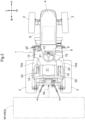
- Fig. 2 is a plan view of the tractor.
- the direction indicated by an arrow F shown in Figs. 1 and 2 is a "forward direction”
- the direction indicated by an arrow B is a “rearward direction”
- the direction indicated by an arrow U is an "upward direction”
- the direction indicated by an arrow D is a “downward direction”
- the direction indicated by an arrow L is a "direction to the left”
- the direction indicated by an arrow R is a "direction to the right”.
- left and right front wheels 2 and left and right rear wheels 3 are disposed on a body 1, an engine E is disposed inward of an engine hood 4 of a front portion of the body 1, and a driver's section 9 is disposed in a rear portion of the body 1.
- This tractor can be equipped with an operating apparatus W1 (represented as virtual lines in Figs. 1 and 2 ) that requires power supply at a position rearward of the body 1, examples of which include an implement of any kind, such as a rotary, an electric implement such as a motor, a water supply apparatus, and a fertilizer supply apparatus.
- the tractor may be equipped with an external device W2 instead of or together with the operating apparatus W1.
- a transmission 5 that shifts the driving force of the engine E is disposed in the area extending from a central portion of the body 1 in the front-rear direction to a rear portion of the body 1.
- an external power take-off (PTO) shaft 34 for transmitting engine power to the operating apparatus W1 requiring engine power is disposed at the rear end of the transmission 5 in such a manner as to protrude rearward.
- a driver's seat 11 on which the driver sits is disposed at an intermediate position between left and right rear wheel fenders 10a that respectively have lever guides 10 on the upper surfaces thereof, and a steering wheel 12 that is used to steer the body 1 is disposed forward of the driver's seat 11.
- a floor 13 is disposed in the driver's section 9, and the floor 13 is equipped with a main shift pedal 19.
- the lever guide 10 on the upper surface of the rear wheel fender 10a on the left of the driver's seat 11 is equipped with a main shift lever 21 and an auxiliary shift lever 23 that protrude upward from the lever guide 10 and are arranged side by side.
- the lever guide 10 on the upper surface of the rear wheel fender 10a on the right of the driver's seat 11 is equipped with a speed shift lever 24 that is used to change the driving speed of the operating apparatus W1, in such a manner as to protrude upward from the lever guide 10.
- Two brake pedals 20 capable of stopping the body 1 are disposed on the floor 13 side by side when viewed forward (along the width direction of the body 1). These two brake pedals 20 on the left and right sides are independent of each other, and are configured so that the driver can apply the brake to the left rear wheel 3 by depressing the left brake pedal 20, and can apply the brake to the right rear wheel 3 of the tractor by depressing the right brake pedal 20.
- an operating apparatus manipulation tool group 25 which is a group of operating apparatus manipulation tools other than the speed shift lever 24 used to manipulate the operating apparatus W1 and the external device W2, is disposed around the driver's seat 11.
- the operating apparatus manipulation tool group 25 may not only be disposed in the body 1, but may also be configured as a remote control.
- the operating apparatus manipulation tool group 25 also includes single manipulation tools such as a single lever and a single switch.
- a battery 6 is disposed forward of the engine E.
- a starter SM or an alternator A are disposed on a front portion of the engine E.
- An instrument panel 8 is disposed forward of the driver's seat 11, and an electronic control unit 7 is disposed below the driver's seat 11.
- an external power feed port 61 which is a power feed socket, is disposed in a rear portion of the body 1. If the external power feed port 61 is configured to feed a current of a predetermined voltage (for example, 100V), a general-purpose electric device can be connected to this external power feed port 61 and used as the external device W2.
- a predetermined voltage for example, 100V
- the operating apparatus W1 is connected to a power feed line 60, which is a cable connected to the battery 6, with the use of a dedicated connector.
- the battery 6, the engine E, the starter SM, the alternator A, the instrument panel 8, the electronic control unit 7, the external power feed port 61, and, in addition, other electrical devices not shown in the drawings are connected to the power feed line 60.
- the power feed line 60 extends substantially straight on the right of the body 1. In this way, the configuration in which the power feed line 60 extends straight on either the right or left of the body 1 is advantageous from the viewpoint of installation and maintenance of the power feed line 60.
- the battery 6 is charged with power generated by the alternator A.
- the engine E, the starter SM, the alternator A, the instrument panel 8, the electronic control unit 7, the external device W2 connected to the external power feed port 61, and the operating apparatus W1 connected to the power feed line 60 are supplied with power generated by the alternator A. If alternator A is stopped, or if the amount of power generated by the alternator A is less than the demand, power is supplied by the battery 6.
- Fig. 4 shows a functional block of the electronic control unit 7 that detects and reports the state of the battery 6.
- the electronic control unit 7 includes a voltage detector 71, a voltage drop amount detector 72, a voltage drop manager 73, an operating apparatus manager 74, and a display controller 75.
- the operating apparatus manager 74 manages the operational states of the operating apparatus W1 mounted on the tractor and the external device W2 connected to the external power feed port 61.
- the external device W2 is treated as equivalent to the operating apparatus W1. Therefore, the operating apparatus manager 74 receives operation signals input from the operating apparatus manipulation tool group 25 for manipulating the operating apparatus W1 and the external device W2, and a dedicated remote control.
- the voltage drop manager 73 sets the operation flag to "ON", which indicates that the operating apparatus W1 or external device W2 is in operation, based on the input operation signal.
- the voltage detector 71 is an electrical circuit connected to the power feed line 60, and detects voltage fluctuations in the power feed line 60.
- the voltage fluctuation detection signal detected by the voltage detector 71 is transmitted to the voltage drop amount detector 72.
- the voltage drop amount detector 72 detects (calculates) the amount of voltage drop in the battery 6 based on the voltage fluctuation detection signal transmitted from the voltage detector 71.
- the voltage drop manager 73 While the operating apparatus W1 or the external device W2 is in operation, i.e., while the voltage drop manager 73 is equipped with an operation flag "ON" from the operating apparatus manager 74, if the amount of voltage drop detected by the voltage drop amount detector 72 exceeds a permissible value, the voltage drop manager 73 creates voltage drop information indicating the state of the voltage drop. If the voltage drop information includes a voltage drop warning command, this voltage drop warning command is disposed to the display controller 75. Based on the received voltage drop warning command, the display controller 75 controls the instrument panel 8, which is one form of the reporting device, to issue a voltage drop warning.
- the voltage drop manager 73 has either one or both of a first mode and a second mode as the mode for issuing a voltage drop warning command.
- the voltage drop manager 73 provides a voltage drop warning command to the display controller 75 when the amount of voltage drop exceeds the permissible value even momentarily.
- the voltage drop manager 73 does not provide a voltage drop warning command to the display controller 75 when the amount of voltage drop momentarily exceeds the permissible value, but provides a voltage drop warning command to the display controller 75 when the amount of voltage drop continuously exceeds the permissible value for a predetermined period of time.
- this voltage drop warning is cancelled when the amount of voltage drop returns to a cancellation value, which is a value lower than the permissible value.
- the reporting and cancellation of the voltage drop warning is performed with controlled hysteresis.
- this controlled hysteresis is not essential, and the reporting of the voltage drop warning may be cancelled without hysteresis.
- Fig. 5 shows an example of the instrument panel 8.
- the instrument panel 8 is built into the front panel that is disposed forward of the driver's section 9.
- This instrument panel 8 has general specifications, with an engine tachometer 80, an engine oil pressure warning light 81, a battery warning light 82, a fuel level gauge 83, and so on arranged therein.
- the display of the instrument panel 8 is controlled by the display controller 75.
- the battery warning light 82 is also used as a voltage drop warning light 8a to report that the voltage drop in the battery 6 exceeds the permissible value.
- the display controller 75 receives a voltage drop warning command from the voltage drop manager 73, the display controller 75 flashes the battery warning light 82, i.e., the voltage drop warning light 8a. That is to say, the battery warning light 82 illuminates when a charging fault occurs in the battery 6 (see (a) in Fig. 5 ), and flashes when the voltage drop exceeds the permissible value of the battery 6 (see (b) in Fig. 5 ).
- Fig. 6 is a flowchart showing an example of processing that is performed to report a voltage drop exceeding the permissible value of the battery 6 during operation of the operating apparatus W1 and the external device W2.
- voltage drop warning processing and operating apparatus management processing start.
- the operating apparatus manager 74 checks whether the operating apparatus W1 (or the external device W2) is in operation or not in operation (#101). If it is in operation (the "IN OPERATION” branch in #101), "ON” is set to the operation flag (#102), and if it is not in operation (the "NOT IN OPERATION” branch in #101), "OFF” is set to the operation flag (#103). The content of the operation flag is referred to in voltage drop warning processing.
- step #04 If the check in step #04 indicates that the content of the operation flag is "ON” (the “ON” branch in #04), it is further checked whether or not the amount of voltage drop is greater than the permissible value (#05). If the amount of voltage drop is greater than the permissible value (the “Yes” branch in #05), "ON” is set to the warning flag by the voltage drop manager 73 (#06) and a voltage drop warning command is created as voltage drop information and issued to the display controller 75 (#07). Upon receiving the voltage drop warning command, the display controller 75 flashes the battery warning light 82 functioning as the voltage drop warning light 8a (#08). Thereafter, processing returns to step #02.
- step #05 If the check in step #05 indicates that the amount of voltage drop is not greater than the permissible value (the "No" branch in #05), it is further checked whether or not the amount of voltage drop is greater than a cancellation value (a value smaller than the permissible value) (#11). If the amount of voltage drop is greater than the cancellation value (the "Yes” branch in #11), processing returns to step #02. That is to say, when no voltage drop warning has been disposed in the current situation, even if the amount of voltage drop is greater than the cancellation value, it is not greater than the permissible value, and therefore processing returns to step #02 without any change to see what happens afterwards.
- a cancellation value a value smaller than the permissible value
- step #04 If the content of the operation flag is "OFF” in the check in step #04 (the "OFF” branch in #04) or if the amount of voltage drop is no greater than the cancellation value in the check in step #11 (the "No” branch in #11), processing proceeds to step #21.
- step #21 it is checked whether the content of the warning flag is "ON” or "OFF".
- This check in step #21 is a check regarding whether or not a voltage drop warning is currently active. If the content of the warning flag is "ON” (the "ON” branch in #21), "OFF” is set to the warning flag (#22) and the warning command serving as voltage drop information is cancelled (#23).
- the display controller 75 stops the battery warning light 82 from flashing and turns it off (#24). Thereafter, processing returns to step #02.
- step #21 If the content of the warning flag is "OFF” in the check in step #21 (the "OFF" branch in #21), processing returns to step #02.
- step #05 if the amount of voltage drop is greater than the permissible value in the check in step #05, the voltage drop manager 73 immediately performs voltage drop warning processing (#06, #07, #08). However, in this step #05, timer processing may be performed so that voltage drop warning processing is only performed when the amount of voltage drop continuously exceeds the permissible value for a predetermined period of time.
- the detection and reporting of a voltage drop according to the above-described present invention is particularly advantageous because the engine speed is kept low and because the operation of the operating apparatus W1 and the external device W2 and the damage to the battery 6 caused by overdischarge can be taken into account when the amount of power generated by the alternator A is low or the capacity of the battery 6 is low.
- the present invention is effective when snow removal work is carried out late at night, as such work is carried out at a low engine speed in order to avoid noise.
- the present invention is effective not only in snow removal, but also in work in low temperature conditions, as the output characteristics of the battery 6 are more likely to deteriorate in such conditions.
- the present invention is also effective at a campsite or the like when electrical devices for camping, such as lamps, are connected to the external power feed port 61 when the engine E is stopped.
- the present invention is applicable to a work vehicle equipped with a battery.
- the present invention is applicable to a program, a recording medium, and a method for a work vehicle equipped with a battery.
Landscapes
- Engineering & Computer Science (AREA)
- Power Engineering (AREA)
- Mechanical Engineering (AREA)
- Transportation (AREA)
- Physics & Mathematics (AREA)
- General Physics & Mathematics (AREA)
- Sustainable Energy (AREA)
- Sustainable Development (AREA)
- Life Sciences & Earth Sciences (AREA)
- Chemical & Material Sciences (AREA)
- Combustion & Propulsion (AREA)
- Secondary Cells (AREA)
- Agricultural Machines (AREA)
- Charge And Discharge Circuits For Batteries Or The Like (AREA)
Abstract
Description
- The present invention relates to a work vehicle including a battery and an operating apparatus that operates on the power supplied by this battery, and capable of reporting the state of the battery to the driver.
- The present invention also relates to a program, a recording medium, and a method.
-
JP 2011-153962A -
JP 2002-283936A - With the tractor according to
JP 2011-153962A - With the apparatus according to
JP 2002-283936A - In view of the above-described circumstances, the present invention aims to provide a work vehicle that enables the driver to appropriately grasp the state of the battery during work and take actions such as charging or replacing the battery in an appropriate manner.
- A work vehicle according to the present invention is equipped with a battery and an operating apparatus configured to be supplied with power from the battery. Furthermore, the work vehicle includes: a reporting device in a driver's section; a voltage drop amount detector configured to detect an amount of voltage drop in the battery; and a voltage drop manager configured to report voltage drop information via the reporting device in response to the amount of voltage drop exceeding a permissible value during operation of the operating apparatus.
- With this configuration, the amount of voltage drop in the battery is monitored when an operating apparatus with high power consumption is operated by the driver, and when the voltage drop exceeds a permissible value, voltage drop information is reported to the driver via the reporting device. This allows the driver to see what kind of operation of the operating apparatus will cause a voltage drop greater than the permissible value in the battery. If such a voltage drop occurs, it is possible to continue work travel while avoiding the corresponding operations as much as possible, and furthermore, it is possible to take measures such as charging or replacing the battery at the right time or at the right place. Note that examples of operating apparatuses include an apparatus that is directly attached to the body of the work vehicle via a coupling mechanism, and another apparatus that is supplied with power from the battery.
- Work vehicles often travel in poor environmental conditions for electrical systems, such as paddy fields and muddy areas. To maintain accurate measurements, the voltage drop detector needs to be protected from water and mud. However, adopting a special protective structure for the voltage drop detector is costly. To solve this problem, it is preferable to install the voltage drop detector in the electronic control unit of the work vehicle, as the electronic control unit on the work vehicle is protected from water and mud by protective measures. Many electronic control units have a built-in power supply circuit that produces a highly accurate voltage, and it is therefore preferable to use the voltage from this power supply circuit for the voltage drop detector. Therefore, in a preferred embodiment, the voltage drop amount detector is installed in an electronic control unit configured to be supplied power from the battery, and is configured to detect the amount of voltage drop based on a detection signal from a voltage detector connected to a power feed line of the battery.
- It is preferable to use visual stimuli to reliably inform the driver during a work travel that a battery voltage drop greater than the permissible value has occurred, as the information is not disturbed by noise or the like. Therefore, in a preferred embodiment, the reporting device is a single voltage drop warning light, and the voltage drop information is reported by flashing of the voltage drop warning light.
- During work travel, the driver looks at the instrument panel, which displays a variety of travel and work information. Therefore, it is preferable that the voltage drop warning light is disposed in the instrument panel or around the instrument panel. Furthermore, the use of the various warning lights located in the instrument panel, particularly the battery warning light, as a voltage drop warning light is advantageous in terms of space and cost. The battery warning light, as is well known, is turned on when an inconvenience to the battery such as an alternator fault or faulty wiring occurs. The mode in which this battery warning light flashes instead of illuminating to report a voltage drop in the battery to the driver is also preferable for the driver. Therefore, in a preferred embodiment, the work vehicle further includes a battery warning light on an instrument panel that is disposed in the driver's section, and the battery warning light is configured to be used as the voltage drop warning light.
- The voltage drop during operation of the operating apparatus varies over time, and therefore there are cases where the voltage drop in the battery momentarily exceeds the permissible value. Such a momentary voltage drop does not greatly affect the battery, and there is no need to report it to the driver. In addition, there are cases where the battery voltage drop exceeding the permissible value and the recovery of the battery voltage occur repeatedly. In such cases, even if the battery voltage momentarily recovers, it will drop again, so it is better not to stop reporting it immediately. To address the former cases, it is preferable that the voltage drop manager is configured to report the voltage drop information in response to the amount of voltage drop continuously exceeding the permissible value for a predetermined period of time. To address the latter cases, it is preferable that the reporting of the voltage drop information is cancelled in response to the amount of voltage drop returning to a cancellation value less than the permissible value, i.e., controlled hysteresis is provided for the detection of the voltage drop and the detection of the voltage recovery.
- In a preferred embodiment of the present invention, the operating apparatus is configured to operate on power supplied by the battery. An operating apparatus that depends on the power supplied by the battery for its operating energy consumes a lot of power during operation. Therefore, it is important to check the voltage drop during operation of the operating apparatus. In addition, even an operating apparatus that operates on rotational power from an engine has components that require power from the battery, and it is therefore necessary to check the voltage drop during the operation of such an operating apparatus.
- In order to carefully check the voltage drop during operation of the operating apparatus, it is necessary to perform operating apparatus management to carefully manage the operation of the operating apparatus. Therefore, in a preferred embodiment of the present invention, the work vehicle includes an operating apparatus manager configured to manage operation of the operating apparatus.
- In a preferred embodiment of the present invention, the work vehicle includes an external power feed port connected to the battery. In work vehicles equipped with an external power feed port, various electrical devices other than the above-mentioned operating apparatuses (e.g. implements) can be connected to the external power feed port as external devices, so that the work vehicle can carry out various tasks. In such cases, it is still possible to check the voltage drop during operation of the electrical device connected to the external power feed port.
- In a preferred embodiment of the present invention, the operating apparatus is equipped with a motor configured to operate on power supplied by the battery. In such a configuration, it is possible to check the voltage drop that may occur depending on the operational state of the motor in the operating apparatus (e.g. implement), and therefore it is possible to suppress damage to the battery while allowing the motor to operate.
- Work vehicles equipped with an operating apparatus with high power consumption have the function of charging the battery with the use of rotational power from the engine. However, the battery cannot be charged sufficiently or at all at low engine speeds below the rated engine speed, at idle speeds, or when the engine is stopped. However, even in embodiments in which the operating apparatus can be operated when the work vehicle is stopped (including when the rotation of the engine is stopped) and when the work vehicle is travelling at low speed (including when the engine is idling), i.e., embodiments in which the operating apparatus can be operated at a reduced engine speed to perform an operation other than normal work of the work vehicle, the present invention makes it possible to operate such an operating apparatus while suppressing damage to the battery by checking the voltage drop during operation of the operating apparatus.
- In a preferrable embodiment of the present invention, the work vehicle further includes an alternator configured to supply power to the battery and the operating apparatus via a cable and having a protective member for current protection in a power supply path, wherein a voltage drop warning light serving as the reporting device is configured to issue a warning in response to an abnormality occurring in the cable or the protective member. With this configuration, the voltage drop check according to the present invention makes it possible not only to detect faults of the alternator, but also to estimate the blowing of a fuse serving as a protective member and the disconnection of a cable, which cannot be detected by conventional work vehicles. This means that it is possible to (virtually) detect alternator-related faults in advance.
- A program according to the present invention is a program for a work vehicle equipped with: a battery; an operating apparatus configured to be supplied with power from the battery; and a reporting device in a driver's section, the program enabling a computer to realize: a voltage drop amount detecting function of detecting an amount of voltage drop in the battery; and a voltage drop managing function of reporting voltage drop information via the reporting device in response to the amount of voltage drop exceeding a permissible value during operation of the operating apparatus.
- A recording medium according to the present invention is a recording medium having recorded thereon a program for a work vehicle equipped with: a battery; an operating apparatus configured to be supplied with power from the battery; and a reporting device in a driver's section, the program enabling a computer to realize: a voltage drop amount detecting function of detecting an amount of voltage drop in the battery; and a voltage drop managing function of reporting voltage drop information via the reporting device in response to the amount of voltage drop exceeding a permissible value during operation of the operating apparatus.
- A method according to the present invention is a method for a work vehicle equipped with: a battery; an operating apparatus configured to be supplied with power from the battery; and a reporting device in a driver's section, the method including: a voltage drop amount detecting step of detecting an amount of voltage drop in the battery; and a voltage drop managing step of reporting voltage drop information via the reporting device in response to the amount of voltage drop exceeding a permissible value during operation of the operating apparatus.
-
- Fig. 1
- is a side view of a tractor, which is an example of a work vehicle.
- Fig. 2
- is a plan view of the tractor.
- Fig. 3
- is a plan view schematically showing the arrangement of a battery and battery-related devices.
- Fig. 4
- is a functional block diagram showing functions related to the reporting of a battery voltage drop.
- Fig. 5
- is a front view of an instrument panel.
- Fig. 6
- is a flowchart showing an example of processing that is performed to report a voltage drop greater than a permissible value of the battery during operation of an operating apparatus or an external device.
- A work vehicle according to the present invention is configured to report a battery voltage drop to the driver. Hereinafter, a work vehicle according to an embodiment will be described, where a tractor is used as an example.
-
Fig. 1 is a side view of the tractor, andFig. 2 is a plan view of the tractor. In the following description, with respect to the tractor, the direction indicated by an arrow F shown inFigs. 1 and2 is a "forward direction", the direction indicated by an arrow B is a "rearward direction", the direction indicated by an arrow U is an "upward direction", the direction indicated by an arrow D is a "downward direction", the direction indicated by an arrow L is a "direction to the left", and the direction indicated by an arrow R is a "direction to the right". - In the tractor, left and right
front wheels 2 and left and rightrear wheels 3 are disposed on abody 1, an engine E is disposed inward of anengine hood 4 of a front portion of thebody 1, and a driver'ssection 9 is disposed in a rear portion of thebody 1. This tractor can be equipped with an operating apparatus W1 (represented as virtual lines inFigs. 1 and2 ) that requires power supply at a position rearward of thebody 1, examples of which include an implement of any kind, such as a rotary, an electric implement such as a motor, a water supply apparatus, and a fertilizer supply apparatus. The tractor may be equipped with an external device W2 instead of or together with the operating apparatus W1. - In the tractor, a
transmission 5 that shifts the driving force of the engine E is disposed in the area extending from a central portion of thebody 1 in the front-rear direction to a rear portion of thebody 1. In addition, an external power take-off (PTO)shaft 34 for transmitting engine power to the operating apparatus W1 requiring engine power is disposed at the rear end of thetransmission 5 in such a manner as to protrude rearward. - In the driver's
section 9, for example, a driver'sseat 11 on which the driver sits is disposed at an intermediate position between left and rightrear wheel fenders 10a that respectively have lever guides 10 on the upper surfaces thereof, and asteering wheel 12 that is used to steer thebody 1 is disposed forward of the driver'sseat 11. Afloor 13 is disposed in the driver'ssection 9, and thefloor 13 is equipped with amain shift pedal 19. Thelever guide 10 on the upper surface of therear wheel fender 10a on the left of the driver'sseat 11 is equipped with amain shift lever 21 and anauxiliary shift lever 23 that protrude upward from thelever guide 10 and are arranged side by side. - The
lever guide 10 on the upper surface of therear wheel fender 10a on the right of the driver'sseat 11 is equipped with aspeed shift lever 24 that is used to change the driving speed of the operating apparatus W1, in such a manner as to protrude upward from thelever guide 10. Twobrake pedals 20 capable of stopping thebody 1 are disposed on thefloor 13 side by side when viewed forward (along the width direction of the body 1). These twobrake pedals 20 on the left and right sides are independent of each other, and are configured so that the driver can apply the brake to the leftrear wheel 3 by depressing theleft brake pedal 20, and can apply the brake to the rightrear wheel 3 of the tractor by depressing theright brake pedal 20. - Furthermore, an operating apparatus
manipulation tool group 25, which is a group of operating apparatus manipulation tools other than thespeed shift lever 24 used to manipulate the operating apparatus W1 and the external device W2, is disposed around the driver'sseat 11. The operating apparatusmanipulation tool group 25 may not only be disposed in thebody 1, but may also be configured as a remote control. The operating apparatusmanipulation tool group 25 also includes single manipulation tools such as a single lever and a single switch. - Next, the power supply system of this tractor will be described with reference to
Fig. 3 . In a front area of thebody 1, abattery 6 is disposed forward of the engine E. A starter SM or an alternator A are disposed on a front portion of the engine E.An instrument panel 8 is disposed forward of the driver'sseat 11, and anelectronic control unit 7 is disposed below the driver'sseat 11. Furthermore, an externalpower feed port 61, which is a power feed socket, is disposed in a rear portion of thebody 1. If the externalpower feed port 61 is configured to feed a current of a predetermined voltage (for example, 100V), a general-purpose electric device can be connected to this externalpower feed port 61 and used as the external device W2. Note that, if the operating apparatus W1 used exclusively for this tractor requires power supply, the operating apparatus W1 is connected to apower feed line 60, which is a cable connected to thebattery 6, with the use of a dedicated connector. Thebattery 6, the engine E, the starter SM, the alternator A, theinstrument panel 8, theelectronic control unit 7, the externalpower feed port 61, and, in addition, other electrical devices not shown in the drawings are connected to thepower feed line 60. InFig. 3 , thepower feed line 60 extends substantially straight on the right of thebody 1. In this way, the configuration in which thepower feed line 60 extends straight on either the right or left of thebody 1 is advantageous from the viewpoint of installation and maintenance of thepower feed line 60. - The
battery 6 is charged with power generated by the alternator A. The engine E, the starter SM, the alternator A, theinstrument panel 8, theelectronic control unit 7, the external device W2 connected to the externalpower feed port 61, and the operating apparatus W1 connected to thepower feed line 60 are supplied with power generated by the alternator A. If alternator A is stopped, or if the amount of power generated by the alternator A is less than the demand, power is supplied by thebattery 6. -
Fig. 4 shows a functional block of theelectronic control unit 7 that detects and reports the state of thebattery 6. In this embodiment, theelectronic control unit 7 includes avoltage detector 71, a voltagedrop amount detector 72, avoltage drop manager 73, anoperating apparatus manager 74, and adisplay controller 75. - The
operating apparatus manager 74 manages the operational states of the operating apparatus W1 mounted on the tractor and the external device W2 connected to the externalpower feed port 61. In this embodiment, the external device W2 is treated as equivalent to the operating apparatus W1. Therefore, theoperating apparatus manager 74 receives operation signals input from the operating apparatusmanipulation tool group 25 for manipulating the operating apparatus W1 and the external device W2, and a dedicated remote control. Thevoltage drop manager 73 sets the operation flag to "ON", which indicates that the operating apparatus W1 or external device W2 is in operation, based on the input operation signal. - The
voltage detector 71 is an electrical circuit connected to thepower feed line 60, and detects voltage fluctuations in thepower feed line 60. The voltage fluctuation detection signal detected by thevoltage detector 71 is transmitted to the voltagedrop amount detector 72. The voltagedrop amount detector 72 detects (calculates) the amount of voltage drop in thebattery 6 based on the voltage fluctuation detection signal transmitted from thevoltage detector 71. - While the operating apparatus W1 or the external device W2 is in operation, i.e., while the
voltage drop manager 73 is equipped with an operation flag "ON" from theoperating apparatus manager 74, if the amount of voltage drop detected by the voltagedrop amount detector 72 exceeds a permissible value, thevoltage drop manager 73 creates voltage drop information indicating the state of the voltage drop. If the voltage drop information includes a voltage drop warning command, this voltage drop warning command is disposed to thedisplay controller 75. Based on the received voltage drop warning command, thedisplay controller 75 controls theinstrument panel 8, which is one form of the reporting device, to issue a voltage drop warning. - The
voltage drop manager 73 has either one or both of a first mode and a second mode as the mode for issuing a voltage drop warning command. In the first mode, thevoltage drop manager 73 provides a voltage drop warning command to thedisplay controller 75 when the amount of voltage drop exceeds the permissible value even momentarily. In the second mode, thevoltage drop manager 73 does not provide a voltage drop warning command to thedisplay controller 75 when the amount of voltage drop momentarily exceeds the permissible value, but provides a voltage drop warning command to thedisplay controller 75 when the amount of voltage drop continuously exceeds the permissible value for a predetermined period of time. In addition, this voltage drop warning is cancelled when the amount of voltage drop returns to a cancellation value, which is a value lower than the permissible value. In other words, the reporting and cancellation of the voltage drop warning is performed with controlled hysteresis. Of course, this controlled hysteresis is not essential, and the reporting of the voltage drop warning may be cancelled without hysteresis. -
Fig. 5 shows an example of theinstrument panel 8. Theinstrument panel 8 is built into the front panel that is disposed forward of the driver'ssection 9. Thisinstrument panel 8 has general specifications, with anengine tachometer 80, an engine oilpressure warning light 81, abattery warning light 82, afuel level gauge 83, and so on arranged therein. The display of theinstrument panel 8 is controlled by thedisplay controller 75. - In this embodiment, the
battery warning light 82 is also used as a voltage drop warning light 8a to report that the voltage drop in thebattery 6 exceeds the permissible value. When thedisplay controller 75 receives a voltage drop warning command from thevoltage drop manager 73, thedisplay controller 75 flashes thebattery warning light 82, i.e., the voltagedrop warning light 8a. That is to say, thebattery warning light 82 illuminates when a charging fault occurs in the battery 6 (see (a) inFig. 5 ), and flashes when the voltage drop exceeds the permissible value of the battery 6 (see (b) inFig. 5 ). -
Fig. 6 is a flowchart showing an example of processing that is performed to report a voltage drop exceeding the permissible value of thebattery 6 during operation of the operating apparatus W1 and the external device W2. When the tractor is driven, voltage drop warning processing and operating apparatus management processing start. - In operating apparatus management processing, the
operating apparatus manager 74 checks whether the operating apparatus W1 (or the external device W2) is in operation or not in operation (#101). If it is in operation (the "IN OPERATION" branch in #101), "ON" is set to the operation flag (#102), and if it is not in operation (the "NOT IN OPERATION" branch in #101), "OFF" is set to the operation flag (#103). The content of the operation flag is referred to in voltage drop warning processing. - In voltage drop warning processing, "OFF" is set to a warning flag in initial processing (#01). When main processing is started, voltage fluctuations in the
battery 6 are detected by the voltage detector 71 (#02). Furthermore, based on the value detected by thevoltage detector 71, the voltagedrop amount detector 72 calculates the amount of voltage drop in the battery 6 (#03). Next, the content of the operation flag is checked (#04). - If the check in
step # 04 indicates that the content of the operation flag is "ON" (the "ON" branch in #04), it is further checked whether or not the amount of voltage drop is greater than the permissible value (#05). If the amount of voltage drop is greater than the permissible value (the "Yes" branch in #05), "ON" is set to the warning flag by the voltage drop manager 73 (#06) and a voltage drop warning command is created as voltage drop information and issued to the display controller 75 (#07). Upon receiving the voltage drop warning command, thedisplay controller 75 flashes thebattery warning light 82 functioning as the voltagedrop warning light 8a (#08). Thereafter, processing returns to step #02. - If the check in
step # 05 indicates that the amount of voltage drop is not greater than the permissible value (the "No" branch in #05), it is further checked whether or not the amount of voltage drop is greater than a cancellation value (a value smaller than the permissible value) (#11). If the amount of voltage drop is greater than the cancellation value (the "Yes" branch in #11), processing returns to step #02. That is to say, when no voltage drop warning has been disposed in the current situation, even if the amount of voltage drop is greater than the cancellation value, it is not greater than the permissible value, and therefore processing returns to step #02 without any change to see what happens afterwards. When a voltage drop warning has been issued in the current situation, it is determined that the amount of voltage drop has fallen below the permissible value, and the voltage drop has recovered to a level between the permissible value and the cancellation value, but the voltage drop has not yet recovered sufficiently to cancel the voltage drop warning. Therefore, thebattery warning light 82 continues to flash, and processing returns to step #02 to see what happens afterwards. - If the content of the operation flag is "OFF" in the check in step #04 (the "OFF" branch in #04) or if the amount of voltage drop is no greater than the cancellation value in the check in step #11 (the "No" branch in #11), processing proceeds to step #21. In
step # 21, it is checked whether the content of the warning flag is "ON" or "OFF". This check instep # 21 is a check regarding whether or not a voltage drop warning is currently active. If the content of the warning flag is "ON" (the "ON" branch in #21), "OFF" is set to the warning flag (#22) and the warning command serving as voltage drop information is cancelled (#23). In response to the cancellation of the warning command, thedisplay controller 75 stops the battery warning light 82 from flashing and turns it off (#24). Thereafter, processing returns to step #02. - If the content of the warning flag is "OFF" in the check in step #21 (the "OFF" branch in #21), processing returns to step #02.
- In this flowchart, if the amount of voltage drop is greater than the permissible value in the check in
step # 05, thevoltage drop manager 73 immediately performs voltage drop warning processing (#06, #07, #08). However, in thisstep # 05, timer processing may be performed so that voltage drop warning processing is only performed when the amount of voltage drop continuously exceeds the permissible value for a predetermined period of time. - The detection and reporting of a voltage drop according to the above-described present invention is particularly advantageous because the engine speed is kept low and because the operation of the operating apparatus W1 and the external device W2 and the damage to the
battery 6 caused by overdischarge can be taken into account when the amount of power generated by the alternator A is low or the capacity of thebattery 6 is low. For example, the present invention is effective when snow removal work is carried out late at night, as such work is carried out at a low engine speed in order to avoid noise. The present invention is effective not only in snow removal, but also in work in low temperature conditions, as the output characteristics of thebattery 6 are more likely to deteriorate in such conditions. The present invention is also effective at a campsite or the like when electrical devices for camping, such as lamps, are connected to the externalpower feed port 61 when the engine E is stopped. -
- (1) The division of the functional units in the functional block diagram shown in
Fig. 4 is an example for clarity of description, and several functional units may be integrated or a single functional unit may be divided into a plurality of units. For example, thevoltage detector 71 and the voltagedrop amount detector 72 may be integrated, or yet another functional unit may be added. In addition, thevoltage detector 71 may be replaced with a functional unit that detects a current and calculates a battery voltage drop as a result. - (2) The arrangement of the electrical components shown in
Figs. 2 and3 is an example, and, for example, the alternator A may be disposed on a rear portion of the engine E. Theelectronic control unit 7 may also be disposed inside the front panel or rearward of the driver'sseat 11. In addition, thepower feed line 60 may be wired in accordance with the layout of the components mounted on thebody 1. - (3) In the above-described embodiment, the voltage
drop warning light 8a that is also used as thebattery warning light 82 is used as a reporting device that reports a battery voltage drop. However, an independent warning light may be used. In addition, together with the voltage drop warning light 8a or instead of the voltagedrop warning light 8a, a loudspeaker or buzzer for reporting voltage drop information by voice, a display for reporting voltage drop information by displaying a message, or the like may be used as a reporting device. - (4) In the above-described embodiment, voltage drop information is reported when the amount of voltage drop in the
battery 6 is greater than the permissible value during the operation of the operating apparatus W1 or the external device W2. However, voltage drop information may be reported when the operating apparatus W1 or the external device W2 is not in operation. In such a case, it is preferable that the reporting modes can be distinguished between when the operating apparatus W1 is in operation and when it is not in operation. Although an operation flag is included in #04 in the processing flow as shown inFig. 6 , this check does not necessarily need to be performed. In other words, the processing flow may start with the detection of voltage fluctuations and the calculation of the amount of voltage drop. - (5) The arrangement of the components around the driver's
section 9 and the driver'sseat 11 described in the above embodiment with reference toFig. 2 , such as the panel, the levers, and the pedals, is an example, and the present invention is not limited to such components or the arrangement thereof. - (6) In the above-described embodiment, a tractor, which is a work vehicle, is described as an example, but the work apparatus may be a work vehicle other than a tractor, i.e., a rice transplanter, a combine harvester, a construction machine, a lawnmower, or a work vehicle for civil engineering work, forest work, snow removal work, etc.
- (7) As shown in
Figs. 4 and6 , the above embodiment describes an apparatus equipped with theoperating apparatus manager 74, an apparatus that performs operating apparatus management processing, and an apparatus that performs a processing flow that involves an operation flag is in #04 inFig. 6 . However, theoperating apparatus manager 74 or the operating apparatus management processing may be omitted. That is to say, the apparatus need only be able to detect voltage fluctuations or calculate the amount of voltage drop, and issue a voltage drop warning based on the detection or the calculation, without detecting the state of the operating apparatus W1. - (8) The above embodiment describes the fact that a general-purpose electric device can be connected to the external
power feed port 61 and used as the external device W2. However, for example, a lamp, an air conditioner, a defogger, etc. may be additionally connected thereto. - (9) In addition, as a component related to the alternator A, a protective member having a fuse function for current protection, which protects the alternator A from abnormal current, may be disposed in the power supply path. The protective member protects the alternator A by being blown when an abnormal current is input thereto. With regards to faults such as the blowing of the protective member and the disconnection of a cable connected to the alternator A, it is very likely that the driver will not notice them until the
battery 6 is dead (the capacity of thebattery 6 runs out) if a fault detection function is not provided. However, the present invention is effective because it enables the driver to know the situation of a voltage drop before thebattery 6 is dead and to avoid any disadvantages for the driver caused by the dead battery. There are a number of inconveniences for the driver caused by a dead battery. Examples of inconveniences include the inability to continue work due to sudden engine failure during night work, increased battery replacement costs due to degraded battery performance as a result of running out of the capacity, delays due to the inability to perform scheduled work, and the preparation and inconvenience of restarting. - (10) The above embodiment shows, as the operating apparatus W1 or the external device W2, an apparatus that is disposed rearward of the
body 1 and that requires power supply, examples of which include an implement of any kind, such as a rotary, an electric implement equipped with a motor, a water supply apparatus, and a fertilizer supply apparatus. However, the operating apparatus W1 and the external device W2 are not limited to these examples. Furthermore, it is provided that the operating apparatus W1 and the external device W2 are used even when the work vehicle is travelling at a low speed or is stopped, and therefore when the work vehicle is travelling at a low speed or is stopped, the rotational speed of the engine E decreases and the output of the alternator A decreases accordingly. The invention according to the present application is also effective under such circumstances. - (11) That is to say, the invention according to the present application is effective when the battery voltage decreases due to a combination of: a decrease in the output characteristics of the battery at low temperature; a decrease in the output of the alternator A due to a low speed of the engine E; an increase in the power consumption of various implements; and an increase in the power consumption due to the use of electrical components. Furthermore, as described above, even in the event of a malfunction of the alternator A or components related to the alternator A, the driver can be informed of the malfunction before the battery runs out.
- (12) The present invention may be embodied as a program that enables a computer to realize the functions of the components in the above embodiment. Alternatively, the present invention may be embodied as a recording medium having recorded thereon a program that enables a computer to realize the functions of the components in the above embodiment. Alternatively, the present invention may be embodied as a method of carrying out by one or more steps what is done by the components in the above embodiment.
- Note that the configurations disclosed in the above embodiments (including modified embodiments, the same applies hereinafter) may be employed in combination with configurations disclosed in Other Embodiments as long as there is no inconsistency. The embodiments disclosed in the present specification are examples, and embodiments of the present invention are not limited thereto, and may be modified as appropriate without departing from the objects of the present invention.
- The present invention is applicable to a work vehicle equipped with a battery.
- Furthermore, the present invention is applicable to a program, a recording medium, and a method for a work vehicle equipped with a battery.
-
- 1
- Body
- 2
- Front Wheel
- 3
- Rear Wheel
- 4
- Engine Hood
- 5
- Transmission
- 6
- Battery
- 7
- Electronic Control Unit
- 8
- Instrument Panel
- 8a
- Voltage Drop Warning Light (Reporting Device)
- 9
- Driver's Section
- 25
- Operating Apparatus Manipulation Tool Group
- 34
- External Power Take-off Shaft
- 60
- Power Feed Line
- 61
- External Power Feed Port
- 71
- Voltage Detector
- 72
- Voltage Drop Amount Detector
- 73
- Voltage Drop Manager
- 74
- Operating Apparatus Manager
- 75
- Display Controller
- 80
- Engine Tachometer
- 81
- Engine Oil Pressure Warning Light
- 82
- Battery Warning Light
- 83
- Fuel Level Gauge
- A
- Alternator
- E
- Engine
- SM
- Starter
- W1
- Operating Apparatus
- W2
- External Device
Claims (15)
- A work vehicle equipped with a battery and an operating apparatus configured to be supplied with power from the battery, the work vehicle comprising:- a reporting device in a driver's section;- a voltage drop amount detector configured to detect an amount of voltage drop in the battery; and- a voltage drop manager configured to report voltage drop information via the reporting device in response to the amount of voltage drop exceeding a permissible value during operation of the operating apparatus.
- The work vehicle according to claim 1,- wherein the voltage drop amount detector is installed in an electronic control unit configured to be supplied power from the battery, and is configured to detect the amount of voltage drop based on a detection signal from a voltage detector connected to a power feed line of the battery.
- The work vehicle according to claim 1 or 2,- wherein the reporting device is a single voltage drop warning light, and- the voltage drop information is reported by flashing of the voltage drop warning light.
- The work vehicle according to claim 3,- wherein the work vehicle further comprises a battery warning light on an instrument panel that is disposed in the driver's section, and- the battery warning light is configured to be used as the voltage drop warning light.
- The work vehicle according to any one of claims 1 to 4,- wherein the voltage drop manager is configured to report the voltage drop information in response to the amount of voltage drop continuously exceeding the permissible value for a predetermined period of time.
- The work vehicle according to any one of claims 1 to 5,- wherein the reporting of the voltage drop information is cancelled in response to the amount of voltage drop returning to a cancellation value less than the permissible value.
- The work vehicle according to any one of claims 1 to 6,- wherein the operating apparatus is configured to operate on power supplied by the battery.
- The work vehicle according to any one of claims 1 to 7, further comprising:- an operating apparatus manager configured to manage operation of the operating apparatus.
- The work vehicle according to any one of claims 1 to 8, further comprising:- an external power feed port connected to the battery.
- The work vehicle according to any one of claims 1 to 9,- wherein the operating apparatus is equipped with a motor configured to operate on power supplied by the battery.
- The work vehicle according to any one of claims 1 to 10,- wherein the operating apparatus is configured to be operable when the work vehicle is stopped and when the work vehicle is travelling at low speed.
- The work vehicle according to any one of claims 1 to 11, further comprising:- an alternator configured to supply power to the battery and the operating apparatus via a cable and having a protective member for current protection in a power supply path,- wherein a voltage drop warning light serving as the reporting device is configured to issue a warning in response to an abnormality occurring in the cable or the protective member.
- A program for a work vehicle equipped with: a battery; an operating apparatus configured to be supplied with power from the battery; and a reporting device in a driver's section, the program enabling a computer to realize:- a voltage drop amount detecting function of detecting an amount of voltage drop in the battery; and- a voltage drop managing function of reporting voltage drop information via the reporting device in response to the amount of voltage drop exceeding a permissible value during operation of the operating apparatus.
- A recording medium having recorded thereon a program for a work vehicle equipped with: a battery; an operating apparatus configured to be supplied with power from the battery; and a reporting device in a driver's section, the program enabling a computer to realize:- a voltage drop amount detecting function of detecting an amount of voltage drop in the battery; and- a voltage drop managing function of reporting voltage drop information via the reporting device in response to the amount of voltage drop exceeding a permissible value during operation of the operating apparatus.
- A method for a work vehicle equipped with: a battery; an operating apparatus configured to be supplied with power from the battery; and a reporting device in a driver's section, the method comprising:- a voltage drop amount detecting step of detecting an amount of voltage drop in the battery; and- a voltage drop managing step of reporting voltage drop information via the reporting device in response to the amount of voltage drop exceeding a permissible value during operation of the operating apparatus.
Applications Claiming Priority (2)
| Application Number | Priority Date | Filing Date | Title |
|---|---|---|---|
| JP2021042721A JP2022142521A (en) | 2021-03-16 | 2021-03-16 | Working vehicle |
| PCT/JP2021/040239 WO2022195948A1 (en) | 2021-03-16 | 2021-11-01 | Work vehicle, program, recording medium, and method |
Publications (2)
| Publication Number | Publication Date |
|---|---|
| EP4309961A1 true EP4309961A1 (en) | 2024-01-24 |
| EP4309961A4 EP4309961A4 (en) | 2025-04-02 |
Family
ID=83320243
Family Applications (1)
| Application Number | Title | Priority Date | Filing Date |
|---|---|---|---|
| EP21931691.6A Pending EP4309961A4 (en) | 2021-03-16 | 2021-11-01 | WORK VEHICLE, PROGRAM, RECORDING MEDIUM AND METHOD |
Country Status (5)
| Country | Link |
|---|---|
| US (1) | US12511957B2 (en) |
| EP (1) | EP4309961A4 (en) |
| JP (1) | JP2022142521A (en) |
| KR (1) | KR20230141850A (en) |
| WO (1) | WO2022195948A1 (en) |
Family Cites Families (17)
| Publication number | Priority date | Publication date | Assignee | Title |
|---|---|---|---|---|
| JPS59204430A (en) * | 1983-05-06 | 1984-11-19 | 日産自動車株式会社 | Battery voltage drop warning device |
| KR19980020805A (en) | 1996-09-11 | 1998-06-25 | 김광호 | Disconnection detection circuit between alternator and battery |
| JP2000329040A (en) * | 1999-05-17 | 2000-11-28 | Fuji Heavy Ind Ltd | Work vehicle |
| JP5162782B2 (en) * | 2000-08-07 | 2013-03-13 | 株式会社小松製作所 | Work machine display |
| JP2002283936A (en) | 2001-03-23 | 2002-10-03 | (合資会社)落合システム研究所 | Power-supply monitoring device for automobile (2) |
| JP2004276672A (en) * | 2003-03-13 | 2004-10-07 | Toyota Motor Corp | Power supply for vehicles |
| KR20040088259A (en) | 2003-04-09 | 2004-10-16 | 현대모비스 주식회사 | Vehicle's battery discharge alarming device |
| US7667611B2 (en) * | 2005-11-30 | 2010-02-23 | Caterpillar Inc. | High voltage detection system |
| KR101262075B1 (en) | 2007-06-15 | 2013-05-08 | 현대자동차주식회사 | Controlling Method of Battery Warning Lamp Using CAN Communication |
| JP5740091B2 (en) | 2010-01-28 | 2015-06-24 | 松山株式会社 | Battery monitoring system for agricultural machines |
| DE102011004545B4 (en) * | 2010-02-24 | 2018-06-28 | Fujitsu Ten Ltd. | Idle stop device, current control method, wear detection method and battery charging method |
| JP5825288B2 (en) * | 2013-04-08 | 2015-12-02 | トヨタ自動車株式会社 | Hybrid vehicle |
| JP6747261B2 (en) * | 2016-11-16 | 2020-08-26 | 株式会社タダノ | Work machine engine restart system and engine restart method |
| JP7096177B2 (en) * | 2019-02-04 | 2022-07-05 | 日立建機株式会社 | Electric drive type work machine |
| JP7243470B2 (en) * | 2019-06-11 | 2023-03-22 | 株式会社デンソー | vehicle equipment |
| JP7620838B2 (en) | 2019-06-17 | 2025-01-24 | パナソニックIpマネジメント株式会社 | Air conditioners |
| JP2021026641A (en) * | 2019-08-08 | 2021-02-22 | 三菱マヒンドラ農機株式会社 | Working vehicle |
-
2021
- 2021-03-16 JP JP2021042721A patent/JP2022142521A/en active Pending
- 2021-11-01 US US18/282,604 patent/US12511957B2/en active Active
- 2021-11-01 WO PCT/JP2021/040239 patent/WO2022195948A1/en not_active Ceased
- 2021-11-01 KR KR1020237029907A patent/KR20230141850A/en not_active Ceased
- 2021-11-01 EP EP21931691.6A patent/EP4309961A4/en active Pending
Also Published As
| Publication number | Publication date |
|---|---|
| US20240169773A1 (en) | 2024-05-23 |
| KR20230141850A (en) | 2023-10-10 |
| JP2022142521A (en) | 2022-09-30 |
| US12511957B2 (en) | 2025-12-30 |
| EP4309961A4 (en) | 2025-04-02 |
| WO2022195948A1 (en) | 2022-09-22 |
Similar Documents
| Publication | Publication Date | Title |
|---|---|---|
| US12162461B2 (en) | Brake control unit | |
| JP2002200948A (en) | Power distribution equipment for vehicles | |
| US10773720B2 (en) | Communication interface for start-stop systems and methods | |
| US10717361B2 (en) | Work vehicle and display device for the work vehicle | |
| JP3629004B2 (en) | Integrated digital control system for automotive electrical equipment | |
| US5734238A (en) | Control system in electric vehicle | |
| US20130072351A1 (en) | Brake monitoring system and method | |
| US20230391220A1 (en) | Control system for electric work vehicle | |
| JP6537464B2 (en) | Work car display device | |
| US20200088270A1 (en) | Work vehicle having implement | |
| CN114137941A (en) | A fault diagnosis and monitoring system for an electric wheeled shovel | |
| US20240167249A1 (en) | Electric Work Machine | |
| KR20150031698A (en) | A Disrlay Device Of Hybrid Tractor and Interface System using the same | |
| US12511957B2 (en) | Work vehicle, program, recording medium, and method | |
| US6087929A (en) | Indication device | |
| US10995722B2 (en) | Work vehicle having engine drive checking circuit | |
| CN103465904A (en) | Method and device for controlling force taking mode of uploading control on pump truck | |
| JP5899909B2 (en) | PTO control device for work vehicle | |
| US6100602A (en) | Service harness overlay procedure for a mobile vehicle | |
| CN110920800B (en) | Override system | |
| EP0291126B1 (en) | Control unit for the pilot lamps of the instrument board of an automotive vehicle | |
| KR20220060126A (en) | Load voltage control system for construction machinery and method for controlling load voltage thereof | |
| JP4227462B2 (en) | Vehicle display system | |
| US20030125861A1 (en) | Control circuit for vehicular power transmission apparatus, and abnormality determining device for the control circuit | |
| KR0171343B1 (en) | Diagnostic device for car parking brake warning circuit using diode |
Legal Events
| Date | Code | Title | Description |
|---|---|---|---|
| STAA | Information on the status of an ep patent application or granted ep patent |
Free format text: STATUS: THE INTERNATIONAL PUBLICATION HAS BEEN MADE |
|
| PUAI | Public reference made under article 153(3) epc to a published international application that has entered the european phase |
Free format text: ORIGINAL CODE: 0009012 |
|
| STAA | Information on the status of an ep patent application or granted ep patent |
Free format text: STATUS: REQUEST FOR EXAMINATION WAS MADE |
|
| 17P | Request for examination filed |
Effective date: 20230921 |
|
| AK | Designated contracting states |
Kind code of ref document: A1 Designated state(s): AL AT BE BG CH CY CZ DE DK EE ES FI FR GB GR HR HU IE IS IT LI LT LU LV MC MK MT NL NO PL PT RO RS SE SI SK SM TR |
|
| DAV | Request for validation of the european patent (deleted) | ||
| DAX | Request for extension of the european patent (deleted) | ||
| REG | Reference to a national code |
Ref country code: DE Ref legal event code: R079 Free format text: PREVIOUS MAIN CLASS: B60R0016040000 Ipc: B60L0001000000 |
|
| A4 | Supplementary search report drawn up and despatched |
Effective date: 20250228 |
|
| RIC1 | Information provided on ipc code assigned before grant |
Ipc: G01R 31/00 20060101ALN20250224BHEP Ipc: G01R 19/165 20060101ALN20250224BHEP Ipc: H02J 7/00 20060101ALI20250224BHEP Ipc: B60R 16/04 20060101ALI20250224BHEP Ipc: B60L 58/14 20190101ALI20250224BHEP Ipc: B60L 3/12 20060101ALI20250224BHEP Ipc: B60L 3/00 20190101ALI20250224BHEP Ipc: B60L 1/00 20060101AFI20250224BHEP |