EP4309896A1 - Additive manufacturing (am) device - Google Patents
Additive manufacturing (am) device Download PDFInfo
- Publication number
- EP4309896A1 EP4309896A1 EP22770923.5A EP22770923A EP4309896A1 EP 4309896 A1 EP4309896 A1 EP 4309896A1 EP 22770923 A EP22770923 A EP 22770923A EP 4309896 A1 EP4309896 A1 EP 4309896A1
- Authority
- EP
- European Patent Office
- Prior art keywords
- powder
- supply device
- ded
- nozzle
- powder material
- Prior art date
- Legal status (The legal status is an assumption and is not a legal conclusion. Google has not performed a legal analysis and makes no representation as to the accuracy of the status listed.)
- Pending
Links
Images







Classifications
-
- B—PERFORMING OPERATIONS; TRANSPORTING
- B33—ADDITIVE MANUFACTURING TECHNOLOGY
- B33Y—ADDITIVE MANUFACTURING, i.e. MANUFACTURING OF THREE-DIMENSIONAL [3D] OBJECTS BY ADDITIVE DEPOSITION, ADDITIVE AGGLOMERATION OR ADDITIVE LAYERING, e.g. BY 3D PRINTING, STEREOLITHOGRAPHY OR SELECTIVE LASER SINTERING
- B33Y30/00—Apparatus for additive manufacturing; Details thereof or accessories therefor
-
- B—PERFORMING OPERATIONS; TRANSPORTING
- B22—CASTING; POWDER METALLURGY
- B22F—WORKING METALLIC POWDER; MANUFACTURE OF ARTICLES FROM METALLIC POWDER; MAKING METALLIC POWDER; APPARATUS OR DEVICES SPECIALLY ADAPTED FOR METALLIC POWDER
- B22F10/00—Additive manufacturing of workpieces or articles from metallic powder
- B22F10/20—Direct sintering or melting
- B22F10/25—Direct deposition of metal particles, e.g. direct metal deposition [DMD] or laser engineered net shaping [LENS]
-
- B—PERFORMING OPERATIONS; TRANSPORTING
- B22—CASTING; POWDER METALLURGY
- B22F—WORKING METALLIC POWDER; MANUFACTURE OF ARTICLES FROM METALLIC POWDER; MAKING METALLIC POWDER; APPARATUS OR DEVICES SPECIALLY ADAPTED FOR METALLIC POWDER
- B22F12/00—Apparatus or devices specially adapted for additive manufacturing; Auxiliary means for additive manufacturing; Combinations of additive manufacturing apparatus or devices with other processing apparatus or devices
- B22F12/22—Driving means
- B22F12/222—Driving means for motion along a direction orthogonal to the plane of a layer
-
- B—PERFORMING OPERATIONS; TRANSPORTING
- B22—CASTING; POWDER METALLURGY
- B22F—WORKING METALLIC POWDER; MANUFACTURE OF ARTICLES FROM METALLIC POWDER; MAKING METALLIC POWDER; APPARATUS OR DEVICES SPECIALLY ADAPTED FOR METALLIC POWDER
- B22F12/00—Apparatus or devices specially adapted for additive manufacturing; Auxiliary means for additive manufacturing; Combinations of additive manufacturing apparatus or devices with other processing apparatus or devices
- B22F12/22—Driving means
- B22F12/224—Driving means for motion along a direction within the plane of a layer
-
- B—PERFORMING OPERATIONS; TRANSPORTING
- B22—CASTING; POWDER METALLURGY
- B22F—WORKING METALLIC POWDER; MANUFACTURE OF ARTICLES FROM METALLIC POWDER; MAKING METALLIC POWDER; APPARATUS OR DEVICES SPECIALLY ADAPTED FOR METALLIC POWDER
- B22F12/00—Apparatus or devices specially adapted for additive manufacturing; Auxiliary means for additive manufacturing; Combinations of additive manufacturing apparatus or devices with other processing apparatus or devices
- B22F12/50—Means for feeding of material, e.g. heads
- B22F12/52—Hoppers
-
- B—PERFORMING OPERATIONS; TRANSPORTING
- B22—CASTING; POWDER METALLURGY
- B22F—WORKING METALLIC POWDER; MANUFACTURE OF ARTICLES FROM METALLIC POWDER; MAKING METALLIC POWDER; APPARATUS OR DEVICES SPECIALLY ADAPTED FOR METALLIC POWDER
- B22F12/00—Apparatus or devices specially adapted for additive manufacturing; Auxiliary means for additive manufacturing; Combinations of additive manufacturing apparatus or devices with other processing apparatus or devices
- B22F12/50—Means for feeding of material, e.g. heads
- B22F12/53—Nozzles
-
- B—PERFORMING OPERATIONS; TRANSPORTING
- B22—CASTING; POWDER METALLURGY
- B22F—WORKING METALLIC POWDER; MANUFACTURE OF ARTICLES FROM METALLIC POWDER; MAKING METALLIC POWDER; APPARATUS OR DEVICES SPECIALLY ADAPTED FOR METALLIC POWDER
- B22F12/00—Apparatus or devices specially adapted for additive manufacturing; Auxiliary means for additive manufacturing; Combinations of additive manufacturing apparatus or devices with other processing apparatus or devices
- B22F12/70—Gas flow means
-
- B—PERFORMING OPERATIONS; TRANSPORTING
- B22—CASTING; POWDER METALLURGY
- B22F—WORKING METALLIC POWDER; MANUFACTURE OF ARTICLES FROM METALLIC POWDER; MAKING METALLIC POWDER; APPARATUS OR DEVICES SPECIALLY ADAPTED FOR METALLIC POWDER
- B22F12/00—Apparatus or devices specially adapted for additive manufacturing; Auxiliary means for additive manufacturing; Combinations of additive manufacturing apparatus or devices with other processing apparatus or devices
- B22F12/90—Means for process control, e.g. cameras or sensors
-
- B—PERFORMING OPERATIONS; TRANSPORTING
- B29—WORKING OF PLASTICS; WORKING OF SUBSTANCES IN A PLASTIC STATE IN GENERAL
- B29C—SHAPING OR JOINING OF PLASTICS; SHAPING OF MATERIAL IN A PLASTIC STATE, NOT OTHERWISE PROVIDED FOR; AFTER-TREATMENT OF THE SHAPED PRODUCTS, e.g. REPAIRING
- B29C64/00—Additive manufacturing, i.e. manufacturing of three-dimensional [3D] objects by additive deposition, additive agglomeration or additive layering, e.g. by 3D printing, stereolithography or selective laser sintering
- B29C64/30—Auxiliary operations or equipment
- B29C64/307—Handling of material to be used in additive manufacturing
- B29C64/321—Feeding
-
- B—PERFORMING OPERATIONS; TRANSPORTING
- B33—ADDITIVE MANUFACTURING TECHNOLOGY
- B33Y—ADDITIVE MANUFACTURING, i.e. MANUFACTURING OF THREE-DIMENSIONAL [3D] OBJECTS BY ADDITIVE DEPOSITION, ADDITIVE AGGLOMERATION OR ADDITIVE LAYERING, e.g. BY 3D PRINTING, STEREOLITHOGRAPHY OR SELECTIVE LASER SINTERING
- B33Y40/00—Auxiliary operations or equipment, e.g. for material handling
-
- B—PERFORMING OPERATIONS; TRANSPORTING
- B33—ADDITIVE MANUFACTURING TECHNOLOGY
- B33Y—ADDITIVE MANUFACTURING, i.e. MANUFACTURING OF THREE-DIMENSIONAL [3D] OBJECTS BY ADDITIVE DEPOSITION, ADDITIVE AGGLOMERATION OR ADDITIVE LAYERING, e.g. BY 3D PRINTING, STEREOLITHOGRAPHY OR SELECTIVE LASER SINTERING
- B33Y50/00—Data acquisition or data processing for additive manufacturing
- B33Y50/02—Data acquisition or data processing for additive manufacturing for controlling or regulating additive manufacturing processes
-
- B—PERFORMING OPERATIONS; TRANSPORTING
- B22—CASTING; POWDER METALLURGY
- B22F—WORKING METALLIC POWDER; MANUFACTURE OF ARTICLES FROM METALLIC POWDER; MAKING METALLIC POWDER; APPARATUS OR DEVICES SPECIALLY ADAPTED FOR METALLIC POWDER
- B22F12/00—Apparatus or devices specially adapted for additive manufacturing; Auxiliary means for additive manufacturing; Combinations of additive manufacturing apparatus or devices with other processing apparatus or devices
- B22F12/50—Means for feeding of material, e.g. heads
- B22F12/55—Two or more means for feeding material
-
- Y—GENERAL TAGGING OF NEW TECHNOLOGICAL DEVELOPMENTS; GENERAL TAGGING OF CROSS-SECTIONAL TECHNOLOGIES SPANNING OVER SEVERAL SECTIONS OF THE IPC; TECHNICAL SUBJECTS COVERED BY FORMER USPC CROSS-REFERENCE ART COLLECTIONS [XRACs] AND DIGESTS
- Y02—TECHNOLOGIES OR APPLICATIONS FOR MITIGATION OR ADAPTATION AGAINST CLIMATE CHANGE
- Y02P—CLIMATE CHANGE MITIGATION TECHNOLOGIES IN THE PRODUCTION OR PROCESSING OF GOODS
- Y02P10/00—Technologies related to metal processing
- Y02P10/25—Process efficiency
Definitions
- the present application relates to an AM apparatus.
- the present application claims priority under the Paris Convention to Japanese Patent Application No. 2021-46034 filed on March 19, 2021 .
- the entire disclosure of Japanese Patent Application No. 2021-46034 including the specification, the claims, the drawings, and the abstract is incorporated herein by reference in its entirety.
- AM Additive Manufacturing
- DED Direct Energy Deposition
- PPF Powder Bed Fusion
- each layer of the three-dimensional object is fabricated by subjecting two-dimensionally bedded metal powder to irradiation of a fabrication target portion thereof with a laser beam or an electron beam serving as a heat source, and melting and solidifying or sintering the metal powder.
- the desired three-dimensional object can be fabricated by repeating such a process.
- the fabrication based on the AM technique is used to manufacture a comparatively small-sized fabrication object at present.
- Manufacturing a relatively large-sized fabrication object using the AM technique leads to the necessity of a large amount of powder material, and makes it important to appropriately supply the powder material.
- a material supply device that supplies the powder material to a DED nozzle should be provided, but the material supply device may be unable to hold the powder material by a sufficient amount when the intended fabrication object is large.
- the powder supply device is set up outside a fabrication region and is configured to supply the powder material to a movable DED nozzle
- a movable DED nozzle such a configuration allows a large-sized material supply device to be provided to the AM apparatus.
- the DED nozzle carries out the fabrication while moving in the fabrication region, a material supply tube extending from the material supply device to the DED nozzle may be deformed according to the movement of the DED nozzle, making stable supply of the material difficult.
- the material supply device is configured movably together with the DED nozzle, the flow path of the material supply tube is stabilized, and the powder material can be stably supplied to the DED nozzle.
- One of objects of the present invention is to provide a structure for replenishing a powder material to a material supply device during fabrication using the AM technique.
- an AM apparatus includes a DED nozzle configured to eject a powder material, a gantry mechanism configured to move the DED nozzle, and a powder supply device configured to supply the powder material to the DED nozzle.
- the gantry mechanism includes a Y-axis member movable in a horizontal X direction and extending in a horizontal Y direction perpendicular to the X direction.
- the DED nozzle and the material supply device are mounted on the Y-axis member of the gantry mechanism.
- the gantry mechanism includes a Y-axis movement mechanism for moving the DED nozzle and the material supply device along the Y direction on the Y-axis member.
- Fig. 1 schematically illustrates an AM apparatus for manufacturing a fabrication object according to one embodiment.
- the AM apparatus includes a base plate 102.
- a fabrication object is going to be fabricated on the base plate 102.
- the base plate 102 can be a plate made from an arbitrary material capable of supporting the fabrication object.
- the base plate 102 is coupled with a lift mechanism movable in a height direction (a z direction). For example, after one layer is fabricated using a DED nozzle 150, the base plate 102 is lowered as long as the thickness of the fabricated one layer using the lift mechanism, and the next layer is fabricated.
- a three-dimensional structure can be fabricated by repeating that.
- the base plate 102 may be coupled with an XY stage movable in an X direction and a Y direction perpendicular to each other in a horizontal plane.
- the AM apparatus 100 includes the DED nozzle 150 for ejecting a powder material.
- the DED nozzle 150 is mounted on a gantry mechanism 200 for moving the DED nozzle 150 in the X and Y directions perpendicular to each other in the horizontal plane.
- a material supply device 300 for supplying carrier gas and the powder material to the DED nozzle 150 is mounted on the gantry mechanism 200.
- the gantry mechanism 200 includes a Y-axis member 202 movable in the X direction and extending in the Y direction perpendicular to the X direction.
- the Y-axis member 202 is a gate-like structure including a horizontal portion 202a extending in the Y direction above a fabrication region 110 and a vertical portion 202b extending from each of the both ends of the horizontal portion 202a toward the fabrication region 110 downward (in the Z direction) as illustrated in Fig. 1 .
- the vertical portion 202b of the Y-axis member 202 is coupled with an X-axis movement mechanism 204.
- the X-axis movement mechanism 204 can be, for example, a movement mechanism including a ball screw. As illustrated in Fig. 1 , the X-axis movement mechanism 204 is disposed along the X axis at each of the both ends of the fabrication region 110 in the Y direction.
- the Y-axis member 202 of the gantry mechanism 200 includes a Y-axis movement mechanism 206 for moving the DED nozzle 150 and the material supply device 300 along the Y direction on the horizontal portion 202a of the Y-axis member 202.
- the Y-axis movement mechanism 206 can be, for example, a movement mechanism including a ball screw. In the embodiment illustrated in Fig. 1 , the DED nozzle 150 and the material supply device 300 are simultaneously moved in the Y direction by the Y-axis movement mechanism 206.
- the Y-axis member 202 includes a Z-axis movement mechanism for moving the DED nozzle 150 in the Z direction.
- the Z-axis movement mechanism can be, for example, a movement mechanism including a ball screw.
- the Z direction is a direction perpendicular to the X direction and the Y direction, and can also be stated as the height direction. The distance of the DED nozzle 150 to the fabrication region 110 can be adjusted by moving the DED nozzle 150 in the Z direction.
- the AM apparatus includes a control device 500.
- the control device 500 is configured to control the operations of various kinds of operation mechanisms of the AM apparatus.
- the control device 500 can be constituted by a general computer or a dedicated computer.
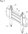
- Fig. 2 is a perspective view schematically illustrating the Y-axis member 202 with the DED nozzle 150 and the material supply device 300 mounted thereon according to one embodiment.
- the Y-axis member 202 includes two DED nozzles 150 and two material supply devices 300.
- the embodiment illustrated in Fig. 2 includes one material supply device 300 for supplying the powder material for one DED nozzle 150, but may be configured in such a manner that the powder material can be supplied from one material supply device 300 to two DED nozzles 150.
- Fig. 3 is a perspective view schematically illustrating the material supply device 300 according to one embodiment.
- Fig. 4 is a cross-sectional view schematically illustrating the structure of the material supply device 300 according to one embodiment.
- the material supply device 300 according to the one embodiment includes a hopper 302 for holding the powder material.
- the hopper 302 has a function as a container that holds the powder material.
- An opening 304 is provided on the upper surface of the hopper 302.
- the powder material is supplied from the opening 304 into the hopper 302.
- a closing member 306 for closing the opening 304 is attached to the upper surface of the hopper 302.
- the closing member 306 is biased in a direction for closing the opening 304 by an elastic member 308.
- the elastic member 308 can be a torsion spring.
- a cap 310 can be provided at the upper end of the hopper 302.
- the cap 310 includes the opening 304, the closing member 306, and the elastic member 308 like the above-described examples.
- Fig. 5 is a cross-sectional view schematically illustrating the cap 310 attached to the hopper 302 according to one embodiment.
- a cover disclosed in Japanese Patent Application No. 2020-169369 can also be used as the cap 310 attached to the hopper 302.
- the powder material can be supplied into the hopper 302 via the opening 304 using a material replenishment tube.
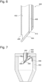
- Fig. 6 is a cross-sectional view schematically illustrating the structure of a material replenishment tube 400 according to one embodiment.
- the material replenishment tube 400 is substantially cylindrically structured.
- the material replenishment tube 400 includes a powder passage 402 used for the powder material to pass therethrough.
- the end portion of the material replenishment tube 400 inserted in the opening 304 of the hopper 302 includes a tapered surface 404.
- a powder port 406 for supplying the powder material into the hopper 302 is provided on the side surface of the material replenishment tube 400 adjacent to the lowest position of the tapered surface 404.
- the material replenishment tube 400 includes a gas passage 408 used for gas to pass therethrough as illustrated in Fig. 6 .
- An opening 410 in communication with the gas passage 408 is provided on the tapered surface 404.
- Fig. 7 is a cross-sectional view schematically illustrating how the material replenishment tube 400 is inserted in the hopper 302 according to one embodiment.
- inserting the material replenishment tube 400 into the opening 304 of the hopper 302 causes the material replenishment tube 400 to push down the closing member 306, allowing the material replenishment tube 400 to access inside the hopper 302.
- the end portion of the material replenishment tube 400 is the tapered surface 404, and the powder port 406 is provided on the side surface. Therefore, after passing through the powder passage 402, the powder material is supplied from the powder port 406 in an oblique direction along the tapered surface 404 serving as the bottom surface.
- the powder material can be prevented from adhering to the upper surface of the closing member 306. If the powder material adheres to the upper surface of the closing member 306, this becomes a cause for impairing the sealing performance of the closing member 306. Further, while the powder material is supplied from the material replenishment tube 400 into the hopper 302, air in the hopper 302 can be discharged out of the hopper 302 via the opening 410 and the gas passage 408.
- the material supply device 300 includes a weight sensor 320 for measuring the weight of the powder material supplied from the hopper 302 to the DED nozzle 150 as illustrated in Fig. 4 .
- the weight sensor 320 is configured to be able to measure the weights of a weighing disk 322 disposed in a case 311 coupled with a hopper exit 312 of the hopper 302 and the powder material supplied to the weighing disk 322.
- the weighing disk 322 is coupled with a motor 323, and is rotatably configured.
- a gas supply tube 332 extending from the carrier gas source 330 is coupled with the case 311.
- a powder supply tube 334 for supplying the carrier gas and the powder material to the DED nozzle 150 is coupled with the weighing disk 322.
- the powder material supplied from the hopper 302 to the weighing disk 322 is supplied from the powder supply tube 334 to the DED nozzle 150 together with the carrier gas.
- the weight of the powder material supplied from the hopper 302 to the DED nozzle 150, i.e., the weight of the consumed powder material can be identified by using the material supply device 300 including the weight sensor 320 configured in the above-described manner. Further, in one embodiment, the weight sensor 320 may be configured to measure the weights of the hopper 302 and the powder material held in the hopper 302.
- the material supply device 300 is movable in the Y direction (the horizontal direction) by the Y-axis movement mechanism 206, and, further, the Y-axis member 202 is also movable in the X direction since being coupled with the X-axis movement mechanism 204. Therefore, the material supply device 300 including the weight sensor 320 is movable in the X direction and the Y direction (i.e., the two directions perpendicular to each other in the horizontal plane), and therefore the weight sensor 320 is also subjected to accelerations in the X direction and the Y direction.
- a sensor not broken even when being subjected to accelerations in the X direction and the Y direction is used as the weight sensor 320.
- the weight sensor in a case of a weight sensor designed with a rated capacity of 15 kg and a maximum load of 150%, the weight sensor is expected to be able to tolerate up to 0.5 G in total as the acceleration(s) in the X direction and/or the Y direction when a load of 15 kg (a total weight of the hopper 320, the powder material, and the like) is placed on the weight sensor.
- the material supply device 300 includes an acceleration sensor 340 as illustrated in Fig. 3 .
- the acceleration sensor 340 can measure accelerations in two directions, the X direction and the Y direction.
- two acceleration sensors each capable of measuring an acceleration in one direction may be provided to the material supply device 300 so as to allow the material supply device 300 to measure the accelerations in the X direction and the Y direction.
- a capacitive-type acceleration sensor or an acceleration sensor based on another arbitrary measurement method can be used as the acceleration sensor 340.
- the X-axis movement mechanism 204 and the Y-axis movement mechanism 206 are controlled in such a manner that the accelerations in the X direction and the Y direction are kept equal to or lower than a predetermined value. More specifically, the control device 500 receives an output from the acceleration sensor 340, and controls the operations of the X-axis movement mechanism 204 and the Y-axis movement mechanism 206 based on the output from the acceleration sensor 340. In one embodiment, the material supply device 300 may be configured to control the operations of the X-axis movement mechanism 204 and the Y-axis movement mechanism 206 within a range that allows the accelerations in the X direction and the Y direction to be kept equal to or lower than the predetermined value without including the acceleration sensor 340.
- the weight sensor 320 is configured to measure the weight only when the material supply device 300 is stopped or is in uniform motion. Configuring the weight sensor 320 to measure the weight only when being stopped or in uniform motion allows the weight sensor 320 to measure the weight without being subjected to a horizontal acceleration, thereby allowing the weight sensor 320 to correctly measure the weight.
- the material supply device 300 includes the powder supply tube 334 for supplying the powder material supplied from the hopper 302 to the DED nozzle 150.
- the powder supply tube 334 is coupled with the weighing disk 322, and the other end of the powder supply tube 334 is coupled with the DED nozzle 150.
- the material supply device 300 includes a sensor 350 for measuring the amount of the powder material passing through the powder supply tube 334.
- Fig. 8 is an enlarged view around the sensor 350 illustrated in Fig. 3 .
- a part of the powder supply tube 334 is constituted by a transparent tube 334t, which is optically transparent, as illustrated in Fig. 8 .
- the sensor 350 includes a light source 352 for irradiating the transparent tube 334t with light and a light-receiving element 354 for receiving the light transmitted through the transparent tube 334t. As illustrated in Fig. 8 , the light source 352 and the light-receiving element 354 are disposed on one side and the other side of the transparent tube 334t, respectively.
- the light source 352 can be an LED light source.
- the sensor 350 in Fig. 8 is a transmission-type sensor, but a reflection-type sensor may be employed as another embodiment.
- the reflection-type sensor for example, the sensor 350 may be constructed in such a manner that a reflection plate is disposed at the position of the light-receiving element 354 in the above-described drawing, Fig. 8 and a light source and a light-receiving element are disposed at the position of the light source 352 in the above-described drawing, Fig. 8 , and light reflected from the reflection plate is received by the light-receiving element.
- a flow of the powder material passing through the transparent tube 334t is irradiated with the light.
- the light is more attenuated and the light received by the light-receiving element 354 has a lower luminous intensity.
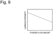
- Fig. 9 is one example of a graph indicating the relationship between the flow amount of the powder passing through the transparent tube 334t and the luminous intensity detected by the light-receiving element 354.
- Pre-measuring a calibration curve indicating the relationship between the amount of the powder material passing through the transparent tube 334t and the luminous intensity like the illustrated example allows the flow amount of the powder material passing through the transparent tube 334t to be detected by measuring the luminous intensity.
- the amount of the powder material supplied from the hopper 302 to the DED nozzle 150 i.e., the amount of the powder material consumed in the AM fabrication can be measured by integrating the luminous intensity of the light received by the light-receiving element 354 over time. Further, identifying the consumed amount of the powder material also makes it possible to estimate the remaining amount of the powder material held in the hopper 302.
- the transparent tube 334t can be made from an electroconductive material. Further, in one embodiment, the transparent tube 334t may be made from an electroconductive material or a non-electroconductive material subjected to an anti-static treatment. Semi-conductive polyurethane, transparent electroconductive glass, or another arbitrary material can be used as the electroconductive transparent material. Further, a PFA-AS tube (Nichias Corporation) can also be used as the transparent tube 334t subjected to the anti-static treatment.
- Fig. 10 is an enlarged view around the sensor 350 illustrated in Fig. 3 according to one embodiment.
- a branch portion is provided upstream of the transparent tube 334t, and one end of the branch portion is coupled with a gas source 356.
- pressurized gas can be supplied from the gas source 356 to the transparent tube 334t.
- the gas in the gas source 356 can be the same gas as the carrier gas, and can be, for example, argon gas.
- the gas source 330 of the carrier gas may be used as the gas source 356.
- the powder material adhering to the surface of the transparent tube 334t can be swept away by feeding the pressurized gas from the gas source 356 to the transparent tube 334t.
- the present embodiment can operate so as to allow the powder material adhering to the surface of the transparent tube 334t to be swept away by feeding the pressurized gas from the gas source 356 to the transparent tube 334t after the fabrication for one layer by the DED nozzle 150 is ended.
- the branch portion and the gas source 356 provided as illustrated in Fig.
- the carrier gas for transporting the powder material supplied from the hopper 302 to the DED nozzle 150 may be supplied from the carrier gas source 330 to the powder supply tube 334 and the transparent tube 334t at a high pressure in a state that the powder material is not supplied.
- the powder material may be entwined with unevenness of the inner surface of the transparent tube 334t and the powder material adhering to the transparent tube 334t may get stuck there even when, for example, a treatment for preventing static charge is applied to the transparent tube 334t or the powder material adhering to the transparent tube 334t is removed using the high-pressure gas as described above.
- the transparency of the transparent tube 334t changes as the usage time increases, which hinders the consumed amount of the powder material from being correctly measured by an optical method working in the above-described manner. Therefore, it is desirable to use the transparent tube 334t having a smooth inner surface that makes it difficult for the powder material to get stuck thereon.
- the surface roughness of the inner surface of the transparent tube 334t is equal to or lower than a half of an average particle diameter of the powder material in use.
- the surface roughness refers to a width dimension of a recessed portion of the unevenness of the inner surface of the transparent tube 334t.
- the dimension of the recessed portion of the unevenness of the inner surface of the transparent tube 334t is desirably 25 ⁇ m or smaller.
- the AM apparatus can be set so as to carry out the AM fabrication after continuously feeding the powder material through the transparent tube 334t only for a predetermined time and causing the powder material to adhere to the transparent tube 334t by a predetermined amount, when the transparent tube 334t is replaced with a new one.
- the powder material easily adheres thereto and a considerable change occurs in the transparency that the transparent tube 334t has when the AM fabrication is in progress.
- the change in the transparency of the transparent tube 334t in use for the AM fabrication can be reduced by feeding the powder material through the transparent tube 334t to create such a state that the powder material adheres to the inner surface of the transparent tube 334t by a certain amount before the transparent tube 334t is used in the AM fabrication after being replaced, like the present embodiment.
- the AM apparatus can operate so as to use the transparent tube 334 in the AM fabrication after feeding the powder material through the transparent tube 334t until the transparency that the transparent tube 334t has when the powder material is not fed therethrough reaches a predetermined value.
- the AM apparatus operates in such a manner that the transparent tube 334t is replaced with a new one when the transparency that the transparent tube 334t has when the powder material is not fed therethrough falls to a further low predetermined value due to continuous use of the transparent tube 334t in the AM fabrication.
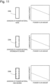
- the calibration curve for calculating the powder flow amount may be changed according to how much the powder material remains on the inner surface of the transparent tube 334t.
- Fig. 11 illustrates examples of a calibration curve when the transparent tube 334t is in a brand-new state with no powder material remaining on the surface of the transparent tube 334t at all, a calibration curve in a state that the powder material adheres/remains on the surface to an intermediate degree, and a calibration curve in a state that the powder material adheres/remains on the surface to a high degree.
- the AM apparatus can operate so as to measure the luminous intensity of the transparent tube 334t without the powder material passing therethrough to detect how much the powder material adheres/remains on the transparent tube 334t, and select the calibration curve to use, before starting the fabrication.
- the AM apparatus may operate so as to regularly measure the luminous intensity of the transparent tube 334t without the powder material passing therethrough to detect how much the powder material adheres/remains on the transparent tube 334t, and select the calibration curve to use, while carrying out the fabrication.
- the calibration curve may be selected according to the above-described procedure after fabrication for one layer is ended and before fabrication of the next layer is started.
- the material supply device 300 includes a sensor 360 for measuring the height of the powder material held in the hopper 302.
- Fig. 12 schematically illustrates the cross-section of the hopper 302 of the material supply device 300 according to one embodiment.
- the sensor 360 of the material supply device 300 includes a light source 362 oriented so as to irradiate the inside of the hopper 302 with light horizontally and a light-receiving element 364 for receiving the light transmitted through inside the hopper 302 at a position of a first height of the hopper 302.
- the material supply device 300 can stop the supply of the powder material to the hopper 302 assuming that the powder material is replenished into the hopper 302 by a sufficient amount, when the powder material blocks the light transmitted through inside the hopper 302 to thus prohibit the light from being detected by the light-receiving element 364 during the replenishment of the powder material into the hopper 302.
- the sensor 360 in Fig. 12 is a transmission-type sensor, but a reflection-type sensor may be employed as another embodiment.
- the reflection-type sensor for example, the sensor 360 may be constructed in such a manner that a reflection plate is disposed at the position of the light-receiving element 364 in the above-described drawing, Fig. 12 and a light source and a light-receiving element are disposed at the position of the light source 362 in the above-described drawing, Fig. 12 , and light reflected from the reflection plate is received by the light-receiving element.
- a vibration may be provided to the hopper 302 to prevent the powder material from being heaped while the powder material is supplied into the hopper 302.
- the vibration provided to the hopper 302 may be, for example, generated by the above-described X-axis movement mechanism 204 or Y-axis movement mechanism 206.
- the amount of the powder material replenished in the hopper 302 may be detected using the above-described weight sensor 320.
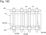
- Figs. 13A, 13B , and 13C are top views schematically illustrating the AM apparatus 100 when the AM fabrication is in progress.
- the AM apparatus 100 includes a plurality of gantry mechanisms 200 and a plurality of DED nozzles 150. These DED nozzles 150 are configured movably in the predetermined fabrication region 110 by the respective gantry mechanisms 200.
- the AM apparatus 100 according to the present embodiment includes a large fabrication region and can manufacture a relatively large-sized fabrication object due to the pluralities of DED nozzles 150 and gantry mechanisms 200.
- Figs. 13A to 13C are top views schematically illustrating the AM apparatus according to the one embodiment, and illustrate the fabrication in progress.
- Fig. 13A illustrates the fabrication in progress, and the positions of the gantry mechanisms 200 and the DED nozzles 150 are moved to various positions according to fabrication positions.
- Fig. 13B illustrates a state that the fabrication for one layer is ended, and each of the DED nozzles 150 is on standby at a retraction position and each of the gantry mechanisms 200 is on standby at a predetermined position.
- the powder material may be replenished into the material supply device 300 while each of the gantry mechanisms 200 and the DED nozzles 150 are on standby.
- the AM apparatus 100 includes a powder bedding mechanism 130.
- the powder bedding mechanism 130 has a function of bedding the powder material over the fabrication region 110.
- An arbitrarily structured mechanism can be used as the powder bedding mechanism 130, and, for example, a powder bedding mechanism for use with an AM apparatus based on the PBF method can be used as it.
- the powder bedding mechanism 130 can bed the powder material over the fabrication region 110 when the DED nozzles 150 and the gantry mechanisms 200 are located at the retraction positions and are on standby.
- the powder bedding mechanism 130 moves while passing under the Y-axis members 202 of the gantry mechanisms 200 to bed the powder material over the fabrication region 110. After that, the next layer can be fabricated as illustrated in Fig. 13A .
Landscapes
- Engineering & Computer Science (AREA)
- Chemical & Material Sciences (AREA)
- Materials Engineering (AREA)
- Manufacturing & Machinery (AREA)
- Mechanical Engineering (AREA)
- Analytical Chemistry (AREA)
- Automation & Control Theory (AREA)
- Physics & Mathematics (AREA)
- Optics & Photonics (AREA)
- Coating Apparatus (AREA)
- Powder Metallurgy (AREA)
- Processing And Handling Of Plastics And Other Materials For Molding In General (AREA)
Abstract
Description
- The present application relates to an AM apparatus. The present application claims priority under the Paris Convention to
Japanese Patent Application No. 2021-46034 filed on March 19, 2021 Japanese Patent Application No. 2021-46034 - There are known techniques for directly fabricating a three-dimensional object based on three-dimensional data on a computer that expresses the three-dimensional object. Known examples thereof include the Additive Manufacturing (AM) technique. As one example thereof, Direct Energy Deposition (DED) is available as the AM technique employing the deposition method. DED is a technique that carries out fabrication by melting and solidifying a metal material together with a base material using an appropriate heat source while supplying the metal material locally. Further, Powder Bed Fusion (PBF) is available as one example of the AM technique. In PBF, each layer of the three-dimensional object is fabricated by subjecting two-dimensionally bedded metal powder to irradiation of a fabrication target portion thereof with a laser beam or an electron beam serving as a heat source, and melting and solidifying or sintering the metal powder. In PBF, the desired three-dimensional object can be fabricated by repeating such a process.
-
- PTL 1:
Japanese Patent Application Laid-Open No. H10-278902 - PTL 2:
Japanese Patent Application Laid-Open No. 2019-137038 - In any of the DED method and the PBF method, the fabrication based on the AM technique is used to manufacture a comparatively small-sized fabrication object at present. Manufacturing a relatively large-sized fabrication object using the AM technique leads to the necessity of a large amount of powder material, and makes it important to appropriately supply the powder material. In a case where the large-sized fabrication object is manufactured by the DED method, a material supply device that supplies the powder material to a DED nozzle should be provided, but the material supply device may be unable to hold the powder material by a sufficient amount when the intended fabrication object is large. For example, if the powder supply device is set up outside a fabrication region and is configured to supply the powder material to a movable DED nozzle, such a configuration allows a large-sized material supply device to be provided to the AM apparatus. However, because the DED nozzle carries out the fabrication while moving in the fabrication region, a material supply tube extending from the material supply device to the DED nozzle may be deformed according to the movement of the DED nozzle, making stable supply of the material difficult. On the other hand, if the material supply device is configured movably together with the DED nozzle, the flow path of the material supply tube is stabilized, and the powder material can be stably supplied to the DED nozzle. However, configuring the material supply device movably together with the DED nozzle makes it difficult to increase the size of the material supply device. This raises the necessity of replenishing the powder material to the material supply device during the fabrication. One of objects of the present invention is to provide a structure for replenishing a powder material to a material supply device during fabrication using the AM technique.
- According to one aspect, an AM apparatus is provided. This AM apparatus includes a DED nozzle configured to eject a powder material, a gantry mechanism configured to move the DED nozzle, and a powder supply device configured to supply the powder material to the DED nozzle. The gantry mechanism includes a Y-axis member movable in a horizontal X direction and extending in a horizontal Y direction perpendicular to the X direction. The DED nozzle and the material supply device are mounted on the Y-axis member of the gantry mechanism. The gantry mechanism includes a Y-axis movement mechanism for moving the DED nozzle and the material supply device along the Y direction on the Y-axis member.
-
-
Fig. 1 schematically illustrates an AM apparatus for manufacturing a fabrication object according to one embodiment. -
Fig. 2 is a perspective view schematically illustrating a Y-axis member with a DED nozzle and a material supply device mounted thereon according to one embodiment. -
Fig. 3 is a perspective view schematically illustrating the material supply device according to one embodiment. -
Fig. 4 is a cross-sectional view schematically illustrating the material supply device according to one embodiment. -
Fig. 5 is a cross-sectional view schematically illustrating a cap attached to a hopper according to one embodiment. -
Fig. 6 is a cross-sectional view schematically illustrating the structure of a material replenishment tube according to one embodiment. -
Fig. 7 is a cross-sectional view schematically illustrating how the material replenishment tube is inserted in the hopper according to one embodiment. -
Fig. 8 is an enlarged view around a sensor illustrated inFig. 3 . -
Fig. 9 is one example of a graph indicating the relationship between a flow amount of powder passing through a transparent tube and a luminous intensity detected by a light-receiving element according to one embodiment. -
Fig. 10 is an enlarged view around the sensor illustrated inFig. 3 according to one embodiment. -
Fig. 11 illustrates examples of a calibration curve when the transparent tube is in a brand-new state with no powder material remaining on the surface of the transparent tube at all, a calibration curve in a state that the powder material adheres/remains on the surface to an intermediate degree, and a calibration curve in a state that the powder material adheres/remains on the surface to a high degree to according to one embodiment. -
Fig. 12 schematically illustrates the cross-section of the hopper of the material supply device according to one embodiment. -
Fig. 13A is a top view schematically illustrating the AM apparatus according to one embodiment. -
Fig. 13B is a top view schematically illustrating the AM apparatus according to the one embodiment. -
Fig. 13C is a top view schematically illustrating the AM apparatus according to the one embodiment. - In the following description, embodiments of an AM apparatus for manufacturing a fabrication object according to the present invention will be described with reference to the accompanying drawings. In the accompanying drawings, the same or similar components will be indicated by the same or similar reference numerals, and redundant descriptions regarding the same or similar components may be omitted in the description of each of the embodiments. Further, features described in each of the embodiments are also applicable to other embodiments in so far as they do not contradict each other.
-
Fig. 1 schematically illustrates an AM apparatus for manufacturing a fabrication object according to one embodiment. As illustrated inFig. 1 , the AM apparatus includes abase plate 102. A fabrication object is going to be fabricated on thebase plate 102. Thebase plate 102 can be a plate made from an arbitrary material capable of supporting the fabrication object. In one embodiment, thebase plate 102 is coupled with a lift mechanism movable in a height direction (a z direction). For example, after one layer is fabricated using aDED nozzle 150, thebase plate 102 is lowered as long as the thickness of the fabricated one layer using the lift mechanism, and the next layer is fabricated. A three-dimensional structure can be fabricated by repeating that. In one embodiment, thebase plate 102 may be coupled with an XY stage movable in an X direction and a Y direction perpendicular to each other in a horizontal plane. - The
AM apparatus 100 includes theDED nozzle 150 for ejecting a powder material. The DEDnozzle 150 is mounted on agantry mechanism 200 for moving theDED nozzle 150 in the X and Y directions perpendicular to each other in the horizontal plane. Further, amaterial supply device 300 for supplying carrier gas and the powder material to theDED nozzle 150 is mounted on thegantry mechanism 200. - In one embodiment, as illustrated in
Fig. 1 , thegantry mechanism 200 includes a Y-axis member 202 movable in the X direction and extending in the Y direction perpendicular to the X direction. The Y-axis member 202 is a gate-like structure including ahorizontal portion 202a extending in the Y direction above afabrication region 110 and avertical portion 202b extending from each of the both ends of thehorizontal portion 202a toward thefabrication region 110 downward (in the Z direction) as illustrated inFig. 1 . Thevertical portion 202b of the Y-axis member 202 is coupled with anX-axis movement mechanism 204. In one embodiment, theX-axis movement mechanism 204 can be, for example, a movement mechanism including a ball screw. As illustrated inFig. 1 , theX-axis movement mechanism 204 is disposed along the X axis at each of the both ends of thefabrication region 110 in the Y direction. - In one embodiment, the Y-
axis member 202 of thegantry mechanism 200 includes a Y-axis movement mechanism 206 for moving theDED nozzle 150 and thematerial supply device 300 along the Y direction on thehorizontal portion 202a of the Y-axis member 202. In one embodiment, the Y-axis movement mechanism 206 can be, for example, a movement mechanism including a ball screw. In the embodiment illustrated inFig. 1 , theDED nozzle 150 and thematerial supply device 300 are simultaneously moved in the Y direction by the Y-axis movement mechanism 206. - In one embodiment, the Y-
axis member 202 includes a Z-axis movement mechanism for moving theDED nozzle 150 in the Z direction. In one embodiment, the Z-axis movement mechanism can be, for example, a movement mechanism including a ball screw. The Z direction is a direction perpendicular to the X direction and the Y direction, and can also be stated as the height direction. The distance of theDED nozzle 150 to thefabrication region 110 can be adjusted by moving theDED nozzle 150 in the Z direction. - In one embodiment, the AM apparatus includes a
control device 500. Thecontrol device 500 is configured to control the operations of various kinds of operation mechanisms of the AM apparatus. Thecontrol device 500 can be constituted by a general computer or a dedicated computer. -
Fig. 2 is a perspective view schematically illustrating the Y-axis member 202 with theDED nozzle 150 and thematerial supply device 300 mounted thereon according to one embodiment. In the embodiment illustrated inFig. 2 , the Y-axis member 202 includes twoDED nozzles 150 and twomaterial supply devices 300. The embodiment illustrated inFig. 2 includes onematerial supply device 300 for supplying the powder material for oneDED nozzle 150, but may be configured in such a manner that the powder material can be supplied from onematerial supply device 300 to twoDED nozzles 150. -
Fig. 3 is a perspective view schematically illustrating thematerial supply device 300 according to one embodiment.Fig. 4 is a cross-sectional view schematically illustrating the structure of thematerial supply device 300 according to one embodiment. Thematerial supply device 300 according to the one embodiment includes ahopper 302 for holding the powder material. Thehopper 302 has a function as a container that holds the powder material. Anopening 304 is provided on the upper surface of thehopper 302. The powder material is supplied from theopening 304 into thehopper 302. As illustrated inFig. 4 , a closingmember 306 for closing theopening 304 is attached to the upper surface of thehopper 302. The closingmember 306 is biased in a direction for closing theopening 304 by anelastic member 308. In one embodiment, theelastic member 308 can be a torsion spring. - In one embodiment, a
cap 310 can be provided at the upper end of thehopper 302. Thecap 310 includes theopening 304, the closingmember 306, and theelastic member 308 like the above-described examples.Fig. 5 is a cross-sectional view schematically illustrating thecap 310 attached to thehopper 302 according to one embodiment. Further, in one embodiment, a cover disclosed inJapanese Patent Application No. 2020-169369 cap 310 attached to thehopper 302. - In one embodiment, the powder material can be supplied into the
hopper 302 via theopening 304 using a material replenishment tube.Fig. 6 is a cross-sectional view schematically illustrating the structure of amaterial replenishment tube 400 according to one embodiment. In the embodiment illustrated inFig. 6 , thematerial replenishment tube 400 is substantially cylindrically structured. In one embodiment, thematerial replenishment tube 400 includes apowder passage 402 used for the powder material to pass therethrough. In the embodiment illustrated inFig. 6 , the end portion of thematerial replenishment tube 400 inserted in theopening 304 of thehopper 302 includes atapered surface 404. In the illustratedmaterial replenishment tube 400, apowder port 406 for supplying the powder material into thehopper 302 is provided on the side surface of thematerial replenishment tube 400 adjacent to the lowest position of the taperedsurface 404. - In one embodiment, the
material replenishment tube 400 includes agas passage 408 used for gas to pass therethrough as illustrated inFig. 6 . Anopening 410 in communication with thegas passage 408 is provided on thetapered surface 404. -
Fig. 7 is a cross-sectional view schematically illustrating how thematerial replenishment tube 400 is inserted in thehopper 302 according to one embodiment. In the embodiment illustrated inFigs. 6 and 7 , inserting thematerial replenishment tube 400 into theopening 304 of thehopper 302 causes thematerial replenishment tube 400 to push down the closingmember 306, allowing thematerial replenishment tube 400 to access inside thehopper 302. In the embodiment illustrated inFigs. 6 and 7 , the end portion of thematerial replenishment tube 400 is the taperedsurface 404, and thepowder port 406 is provided on the side surface. Therefore, after passing through thepowder passage 402, the powder material is supplied from thepowder port 406 in an oblique direction along the taperedsurface 404 serving as the bottom surface. As a result, the powder material can be prevented from adhering to the upper surface of the closingmember 306. If the powder material adheres to the upper surface of the closingmember 306, this becomes a cause for impairing the sealing performance of the closingmember 306. Further, while the powder material is supplied from thematerial replenishment tube 400 into thehopper 302, air in thehopper 302 can be discharged out of thehopper 302 via theopening 410 and thegas passage 408. - In one embodiment, the
material supply device 300 includes aweight sensor 320 for measuring the weight of the powder material supplied from thehopper 302 to theDED nozzle 150 as illustrated inFig. 4 . As illustrated inFig. 4 , theweight sensor 320 is configured to be able to measure the weights of a weighingdisk 322 disposed in acase 311 coupled with ahopper exit 312 of thehopper 302 and the powder material supplied to the weighingdisk 322. The weighingdisk 322 is coupled with amotor 323, and is rotatably configured. A gas supply tube 332 extending from thecarrier gas source 330 is coupled with thecase 311. Further, apowder supply tube 334 for supplying the carrier gas and the powder material to theDED nozzle 150 is coupled with the weighingdisk 322. The powder material supplied from thehopper 302 to the weighingdisk 322 is supplied from thepowder supply tube 334 to theDED nozzle 150 together with the carrier gas. The weight of the powder material supplied from thehopper 302 to theDED nozzle 150, i.e., the weight of the consumed powder material can be identified by using thematerial supply device 300 including theweight sensor 320 configured in the above-described manner. Further, in one embodiment, theweight sensor 320 may be configured to measure the weights of thehopper 302 and the powder material held in thehopper 302. - As described with reference to
Fig. 1 , thematerial supply device 300 is movable in the Y direction (the horizontal direction) by the Y-axis movement mechanism 206, and, further, the Y-axis member 202 is also movable in the X direction since being coupled with theX-axis movement mechanism 204. Therefore, thematerial supply device 300 including theweight sensor 320 is movable in the X direction and the Y direction (i.e., the two directions perpendicular to each other in the horizontal plane), and therefore theweight sensor 320 is also subjected to accelerations in the X direction and the Y direction. In light thereof, desirably, a sensor not broken even when being subjected to accelerations in the X direction and the Y direction is used as theweight sensor 320. For example, in a case of a weight sensor designed with a rated capacity of 15 kg and a maximum load of 150%, the weight sensor is expected to be able to tolerate up to 0.5 G in total as the acceleration(s) in the X direction and/or the Y direction when a load of 15 kg (a total weight of thehopper 320, the powder material, and the like) is placed on the weight sensor. Then, "G" represents a gravitational acceleration (= 9.8 m/s2). - However, the
weight sensor 320 having a large rated capacity is accompanied by a reduction in the resolution of measuring a weight. Therefore, the operations of theX-axis movement mechanism 204 and the Y-axis movement mechanism 206 may be controlled so as to reduce the horizontal acceleration without increasing the rated capacity of theweight sensor 320 so much. In one embodiment, thematerial supply device 300 includes anacceleration sensor 340 as illustrated inFig. 3 . Desirably, theacceleration sensor 340 can measure accelerations in two directions, the X direction and the Y direction. Alternatively, two acceleration sensors each capable of measuring an acceleration in one direction may be provided to thematerial supply device 300 so as to allow thematerial supply device 300 to measure the accelerations in the X direction and the Y direction. In one embodiment, a capacitive-type acceleration sensor or an acceleration sensor based on another arbitrary measurement method can be used as theacceleration sensor 340. - In one embodiment, the
X-axis movement mechanism 204 and the Y-axis movement mechanism 206 are controlled in such a manner that the accelerations in the X direction and the Y direction are kept equal to or lower than a predetermined value. More specifically, thecontrol device 500 receives an output from theacceleration sensor 340, and controls the operations of theX-axis movement mechanism 204 and the Y-axis movement mechanism 206 based on the output from theacceleration sensor 340. In one embodiment, thematerial supply device 300 may be configured to control the operations of theX-axis movement mechanism 204 and the Y-axis movement mechanism 206 within a range that allows the accelerations in the X direction and the Y direction to be kept equal to or lower than the predetermined value without including theacceleration sensor 340. - In one embodiment, the
weight sensor 320 is configured to measure the weight only when thematerial supply device 300 is stopped or is in uniform motion. Configuring theweight sensor 320 to measure the weight only when being stopped or in uniform motion allows theweight sensor 320 to measure the weight without being subjected to a horizontal acceleration, thereby allowing theweight sensor 320 to correctly measure the weight. - As illustrated in
Figs. 3 and4 , thematerial supply device 300 includes thepowder supply tube 334 for supplying the powder material supplied from thehopper 302 to theDED nozzle 150. In the illustrated embodiment, one end of thepowder supply tube 334 is coupled with the weighingdisk 322, and the other end of thepowder supply tube 334 is coupled with theDED nozzle 150. - In one embodiment, the
material supply device 300 includes asensor 350 for measuring the amount of the powder material passing through thepowder supply tube 334.Fig. 8 is an enlarged view around thesensor 350 illustrated inFig. 3 . In one embodiment, a part of thepowder supply tube 334 is constituted by atransparent tube 334t, which is optically transparent, as illustrated inFig. 8 . In the present embodiment, thesensor 350 includes alight source 352 for irradiating thetransparent tube 334t with light and a light-receivingelement 354 for receiving the light transmitted through thetransparent tube 334t. As illustrated inFig. 8 , thelight source 352 and the light-receivingelement 354 are disposed on one side and the other side of thetransparent tube 334t, respectively. In one embodiment, thelight source 352 can be an LED light source. Further, thesensor 350 inFig. 8 is a transmission-type sensor, but a reflection-type sensor may be employed as another embodiment. As the reflection-type sensor, for example, thesensor 350 may be constructed in such a manner that a reflection plate is disposed at the position of the light-receivingelement 354 in the above-described drawing,Fig. 8 and a light source and a light-receiving element are disposed at the position of thelight source 352 in the above-described drawing,Fig. 8 , and light reflected from the reflection plate is received by the light-receiving element. - In the case where the
optical sensor 350 illustrated inFig. 8 is used, a flow of the powder material passing through thetransparent tube 334t is irradiated with the light. As the powder material passes through thetransparent tube 334t by a larger amount, the light is more attenuated and the light received by the light-receivingelement 354 has a lower luminous intensity. For example,Fig. 9 is one example of a graph indicating the relationship between the flow amount of the powder passing through thetransparent tube 334t and the luminous intensity detected by the light-receivingelement 354. Pre-measuring a calibration curve indicating the relationship between the amount of the powder material passing through thetransparent tube 334t and the luminous intensity like the illustrated example allows the flow amount of the powder material passing through thetransparent tube 334t to be detected by measuring the luminous intensity. The amount of the powder material supplied from thehopper 302 to theDED nozzle 150, i.e., the amount of the powder material consumed in the AM fabrication can be measured by integrating the luminous intensity of the light received by the light-receivingelement 354 over time. Further, identifying the consumed amount of the powder material also makes it possible to estimate the remaining amount of the powder material held in thehopper 302. - If a non-electroconductive material is used as the material of the
transparent tube 334t, the powder material may adhere to the inner surface of thetransparent tube 334t due to an elastic force, hindering thesensor 350 from appropriately measuring the amount of the powder material passing through thetransparent tube 334t. In light thereof, in one embodiment, thetransparent tube 334t can be made from an electroconductive material. Further, in one embodiment, thetransparent tube 334t may be made from an electroconductive material or a non-electroconductive material subjected to an anti-static treatment. Semi-conductive polyurethane, transparent electroconductive glass, or another arbitrary material can be used as the electroconductive transparent material. Further, a PFA-AS tube (Nichias Corporation) can also be used as thetransparent tube 334t subjected to the anti-static treatment. -
Fig. 10 is an enlarged view around thesensor 350 illustrated inFig. 3 according to one embodiment. In the embodiment illustrated inFig. 10 , a branch portion is provided upstream of thetransparent tube 334t, and one end of the branch portion is coupled with agas source 356. In the embodiment illustrated inFig. 10 , pressurized gas can be supplied from thegas source 356 to thetransparent tube 334t. The gas in thegas source 356 can be the same gas as the carrier gas, and can be, for example, argon gas. Further, thegas source 330 of the carrier gas may be used as thegas source 356. In the embodiment illustrated inFig. 10 , the powder material adhering to the surface of thetransparent tube 334t can be swept away by feeding the pressurized gas from thegas source 356 to thetransparent tube 334t. For example, the present embodiment can operate so as to allow the powder material adhering to the surface of thetransparent tube 334t to be swept away by feeding the pressurized gas from thegas source 356 to thetransparent tube 334t after the fabrication for one layer by theDED nozzle 150 is ended. Alternatively, as one embodiment, the branch portion and thegas source 356 provided as illustrated inFig. 10 may be omitted, and the carrier gas for transporting the powder material supplied from thehopper 302 to theDED nozzle 150 may be supplied from thecarrier gas source 330 to thepowder supply tube 334 and thetransparent tube 334t at a high pressure in a state that the powder material is not supplied. - The powder material may be entwined with unevenness of the inner surface of the
transparent tube 334t and the powder material adhering to thetransparent tube 334t may get stuck there even when, for example, a treatment for preventing static charge is applied to thetransparent tube 334t or the powder material adhering to thetransparent tube 334t is removed using the high-pressure gas as described above. In this case, the transparency of thetransparent tube 334t changes as the usage time increases, which hinders the consumed amount of the powder material from being correctly measured by an optical method working in the above-described manner. Therefore, it is desirable to use thetransparent tube 334t having a smooth inner surface that makes it difficult for the powder material to get stuck thereon. Desirably, the surface roughness of the inner surface of thetransparent tube 334t is equal to or lower than a half of an average particle diameter of the powder material in use. The surface roughness refers to a width dimension of a recessed portion of the unevenness of the inner surface of thetransparent tube 334t. As one example, in a case where the powder material having an average particle diameter of 50 µm is used, the dimension of the recessed portion of the unevenness of the inner surface of thetransparent tube 334t is desirably 25 µm or smaller. - In one embodiment, the AM apparatus can be set so as to carry out the AM fabrication after continuously feeding the powder material through the
transparent tube 334t only for a predetermined time and causing the powder material to adhere to thetransparent tube 334t by a predetermined amount, when thetransparent tube 334t is replaced with a new one. In the case of the brand-newtransparent tube 334t, the powder material easily adheres thereto and a considerable change occurs in the transparency that thetransparent tube 334t has when the AM fabrication is in progress. The change in the transparency of thetransparent tube 334t in use for the AM fabrication can be reduced by feeding the powder material through thetransparent tube 334t to create such a state that the powder material adheres to the inner surface of thetransparent tube 334t by a certain amount before thetransparent tube 334t is used in the AM fabrication after being replaced, like the present embodiment. For example, the AM apparatus can operate so as to use thetransparent tube 334 in the AM fabrication after feeding the powder material through thetransparent tube 334t until the transparency that thetransparent tube 334t has when the powder material is not fed therethrough reaches a predetermined value. Further, the AM apparatus operates in such a manner that thetransparent tube 334t is replaced with a new one when the transparency that thetransparent tube 334t has when the powder material is not fed therethrough falls to a further low predetermined value due to continuous use of thetransparent tube 334t in the AM fabrication. - Further, in one embodiment, the calibration curve for calculating the powder flow amount may be changed according to how much the powder material remains on the inner surface of the
transparent tube 334t. For example,Fig. 11 illustrates examples of a calibration curve when thetransparent tube 334t is in a brand-new state with no powder material remaining on the surface of thetransparent tube 334t at all, a calibration curve in a state that the powder material adheres/remains on the surface to an intermediate degree, and a calibration curve in a state that the powder material adheres/remains on the surface to a high degree. As one example, the AM apparatus can operate so as to measure the luminous intensity of thetransparent tube 334t without the powder material passing therethrough to detect how much the powder material adheres/remains on thetransparent tube 334t, and select the calibration curve to use, before starting the fabrication. Alternatively, the AM apparatus may operate so as to regularly measure the luminous intensity of thetransparent tube 334t without the powder material passing therethrough to detect how much the powder material adheres/remains on thetransparent tube 334t, and select the calibration curve to use, while carrying out the fabrication. As one example, the calibration curve may be selected according to the above-described procedure after fabrication for one layer is ended and before fabrication of the next layer is started. - In one embodiment, the
material supply device 300 includes asensor 360 for measuring the height of the powder material held in thehopper 302.Fig. 12 schematically illustrates the cross-section of thehopper 302 of thematerial supply device 300 according to one embodiment. In the embodiment illustrated inFig. 12 , thesensor 360 of thematerial supply device 300 includes alight source 362 oriented so as to irradiate the inside of thehopper 302 with light horizontally and a light-receivingelement 364 for receiving the light transmitted through inside thehopper 302 at a position of a first height of thehopper 302. Thematerial supply device 300 according to this embodiment can stop the supply of the powder material to thehopper 302 assuming that the powder material is replenished into thehopper 302 by a sufficient amount, when the powder material blocks the light transmitted through inside thehopper 302 to thus prohibit the light from being detected by the light-receivingelement 364 during the replenishment of the powder material into thehopper 302. Further, thesensor 360 inFig. 12 is a transmission-type sensor, but a reflection-type sensor may be employed as another embodiment. As the reflection-type sensor, for example, thesensor 360 may be constructed in such a manner that a reflection plate is disposed at the position of the light-receivingelement 364 in the above-described drawing,Fig. 12 and a light source and a light-receiving element are disposed at the position of thelight source 362 in the above-described drawing,Fig. 12 , and light reflected from the reflection plate is received by the light-receiving element. - In the embodiment illustrated in
Fig. 12 , while the powder material is replenished into thehopper 302, the supplied powder material may be piled into a heap to thus hinder the amount of the powder material supplied in thehopper 302 from being correctly detected. In light thereof, in one embodiment, a vibration may be provided to thehopper 302 to prevent the powder material from being heaped while the powder material is supplied into thehopper 302. The vibration provided to thehopper 302 may be, for example, generated by the above-describedX-axis movement mechanism 204 or Y-axis movement mechanism 206. - Further, in one embodiment, the amount of the powder material replenished in the
hopper 302 may be detected using the above-describedweight sensor 320. -
Figs. 13A, 13B , and13C are top views schematically illustrating theAM apparatus 100 when the AM fabrication is in progress. In the embodiment illustrated inFigs. 13A to 13C , theAM apparatus 100 includes a plurality ofgantry mechanisms 200 and a plurality ofDED nozzles 150. TheseDED nozzles 150 are configured movably in thepredetermined fabrication region 110 by therespective gantry mechanisms 200. TheAM apparatus 100 according to the present embodiment includes a large fabrication region and can manufacture a relatively large-sized fabrication object due to the pluralities ofDED nozzles 150 andgantry mechanisms 200. -
Figs. 13A to 13C are top views schematically illustrating the AM apparatus according to the one embodiment, and illustrate the fabrication in progress.Fig. 13A illustrates the fabrication in progress, and the positions of thegantry mechanisms 200 and theDED nozzles 150 are moved to various positions according to fabrication positions.Fig. 13B illustrates a state that the fabrication for one layer is ended, and each of theDED nozzles 150 is on standby at a retraction position and each of thegantry mechanisms 200 is on standby at a predetermined position. The powder material may be replenished into thematerial supply device 300 while each of thegantry mechanisms 200 and theDED nozzles 150 are on standby. - In the embodiment illustrated in
Figs. 13A to 13C , theAM apparatus 100 includes apowder bedding mechanism 130. Thepowder bedding mechanism 130 has a function of bedding the powder material over thefabrication region 110. An arbitrarily structured mechanism can be used as thepowder bedding mechanism 130, and, for example, a powder bedding mechanism for use with an AM apparatus based on the PBF method can be used as it. As illustrated inFig. 13C , thepowder bedding mechanism 130 can bed the powder material over thefabrication region 110 when theDED nozzles 150 and thegantry mechanisms 200 are located at the retraction positions and are on standby. As one example, thepowder bedding mechanism 130 moves while passing under the Y-axis members 202 of thegantry mechanisms 200 to bed the powder material over thefabrication region 110. After that, the next layer can be fabricated as illustrated inFig. 13A . - At least the following technical ideas can be recognized from the above-described embodiments.
- [Configuration 1] According to a configuration 1, an AM apparatus is provided. This AM apparatus includes a DED nozzle configured to eject a powder material, a gantry mechanism configured to move the DED nozzle, and a powder supply device configured to supply the powder material to the DED nozzle. The gantry mechanism includes a Y-axis member movable in a horizontal X direction and extending in a horizontal Y direction perpendicular to the X direction. The DED nozzle and the material supply device are mounted on the Y-axis member of the gantry mechanism. The gantry mechanism includes a Y-axis movement mechanism for moving the DED nozzle and the material supply device along the Y direction on the Y-axis member.
- [Configuration 2] According to a configuration 2, in the AM apparatus according to the configuration 1, the gantry mechanism includes a Z-axis movement mechanism for moving the DED nozzle in a Z direction perpendicular to the X direction and the Y direction.
- [Configuration 3] According to a configuration 3, in the AM apparatus according to the configuration 1 or 2, the material supply device includes a container for holding the powder material and a cap attached to an upper end of the container. The cap includes an opening in communication with an inside of the container, a closing member movable between a closing position, at which the closing member closes the opening, and an opening position, at which the closing member opens the opening, and an elastic member configured to bias the closing member to the closing position.
- [Configuration 4] According to a configuration 4, the AM apparatus according to the configuration 3 further includes a powder replenishment tube insertable in the opening of the cap. The powder replenishment tube includes a powder passage configured to allow the powder material to pass therethrough, and a gas passage different from the powder passage and configured to allow gas to pass therethrough.
- [Configuration 5] According to a configuration 5, in the AM apparatus according to the configuration 4, the powder replenishment tube includes a tapered surface on a distal end side inserted in the opening of the cap, and a powder port for supplying the powder material to the container is formed on a side surface adjacent to a lowest position of the tapered surface.
- [Configuration 6] According to a configuration 6, the AM apparatus according to any one of the configurations 1 to 5 further includes a weight sensor configured to measure a weight of the powder material supplied from the material supply device to the DED nozzle.
- [Configuration 7] According to a configuration 7, in the AM apparatus according to the configuration 6, the Y-axis movement mechanism is configured to control a movement of the material supply device in such a manner that a horizontal acceleration applied to the weight sensor is kept equal to or lower than a predetermined value.
- [Configuration 8] According to a configuration 8, the AM apparatus according to the configuration 6 or 7 further includes an acceleration sensor configured to measure an acceleration applied to the weight sensor.
- [Configuration 9] According to a configuration 9, in the AM apparatus according to any one of the configurations 6 to 8, the weight sensor is configured to measure the weight of the material supply device only when the material supply device is stopped or is in a uniform motion.
- [Configuration 10] According to a configuration 10, the AM apparatus according to any one of the configurations 1 to 9 further includes a powder supply tube configured to supply the powder material from the material supply device to the DED nozzle, and a sensor configured to measure an amount of the powder material that passes through the powder supply tube.
- [Configuration 11] According to a configuration 11, in the AM apparatus according to the configuration 10, at least a part of the powder supply tube is made of a transparent tube that is optically transparent. The AM apparatus further includes a light source configured to irradiate the transparent tube with light, and a light-receiving element configured to receive the light transmitted through the transparent tube.
- [Configuration 12] According to a configuration 12, in the AM apparatus according to the configuration 11, the transparent tube is made from an anti-static member.
- [Configuration 13] According to a configuration 13, in the AM apparatus according to the configuration 11 or 12, the powder supply tube is coupled with a gas source on an upstream side of the transparent tube.
- [Configuration 14] According to a configuration 14, in the AM apparatus according to any one of the configurations 11 to 13, the AM apparatus is configured in such a manner that an inner surface of the transparent tube has a surface roughness equal to or lower than a half of an average particle diameter of the powder material.
- [Configuration 15] According to a configuration 15, in the AM apparatus according to any one of the configurations 1 to 14, the material supply device includes a container for holding the powder material. The AM apparatus further includes a light source configured to irradiate an inside of the container with light at a first height of the container, and a light-receiving element configured to receive the light transmitted through the inside of the container at the first height.
- [Configuration 16] According to a configuration 16, in the AM apparatus according to any one of the configurations 1 to 15, the material supply device is configured in such a manner that a vibration is provided to the material supply device when the powder material is supplied to the material supply device.
-
- 100
- AM apparatus
- 110
- fabrication region
- 130
- powder bedding mechanism
- 150
- DED nozzle
- 200
- gantry mechanism
- 202
- Y-axis member
- 204
- X-axis movement mechanism
- 206
- Y-axis movement mechanism
- 300
- material supply device
- 302
- hopper
- 304
- opening
- 306
- closing member
- 308
- elastic member
- 310
- cap
- 312
- hopper exit
- 320
- weight sensor
- 322
- weighing disk
- 330
- carrier gas source
- 330
- gas source
- 332
- gas supply tube
- 334
- powder supply tube
- 334t
- transparent tube
- 340
- acceleration sensor
- 352
- light source
- 354
- light-receiving element
- 356
- gas source
- 362
- light source
- 364
- light-receiving element
- 400
- material replenishment tube
- 402
- powder passage
- 404
- tapered surface
- 406
- powder port
- 408
- gas passage
- 410
- opening
- 500
- control device
Claims (16)
- An AM apparatus comprising:a DED nozzle configured to eject a powder material;a gantry mechanism configured to move the DED nozzle; anda powder supply device configured to supply the powder material to the DED nozzle,wherein the gantry mechanism includes a Y-axis member movable in a horizontal X direction and extending in a horizontal Y direction perpendicular to the X direction,wherein the DED nozzle and the material supply device are mounted on the Y-axis member of the gantry mechanism, andwherein the gantry mechanism includes a Y-axis movement mechanism for moving the DED nozzle and the material supply device along the Y direction on the Y-axis member.
- The AM apparatus according to claim 1, wherein the gantry mechanism includes a Z-axis movement mechanism for moving the DED nozzle in a Z direction perpendicular to the X direction and the Y direction.
- The AM apparatus according to claim 1 or 2, wherein the material supply device includes a container for holding the powder material and a cap attached to an upper end of the container, andwherein the cap includesan opening in communication with an inside of the container,a closing member movable between a closing position, at which the closing member closes the opening, and an opening position, at which the closing member opens the opening, andan elastic member configured to bias the closing member to the closing position.
- The AM apparatus according to claim 3, further comprising a powder replenishment tube insertable in the opening of the cap,wherein the powder replenishment tube includesa powder passage configured to allow the powder material to pass therethrough, anda gas passage different from the powder passage, the gas passage being configured to allow gas to pass therethrough.
- The AM apparatus according to claim 4, wherein the powder replenishment tube includes a tapered surface on a distal end side inserted in the opening of the cap, and a powder port for supplying the powder material to the container is formed on a side surface adjacent to a lowest position of the tapered surface.
- The AM apparatus according to any one of claims 1 to 5, further comprising a weight sensor configured to measure a weight of the powder material supplied from the material supply device to the DED nozzle.
- The AM apparatus according to claim 6, wherein the Y-axis movement mechanism is configured to control a movement of the material supply device in such a manner that a horizontal acceleration applied to the weight sensor is kept equal to or lower than a predetermined value.
- The AM apparatus according to claim 6 or 7, further comprising an acceleration sensor configured to measure an acceleration applied to the weight sensor.
- The AM apparatus according to any one of claims 6 to 8, wherein the weight sensor is configured to measure the weight of the material supply device only when the material supply device is stopped or is in a uniform motion.
- The AM apparatus according to any one of claims 1 to 9, further comprising:a powder supply tube configured to supply the powder material from the material supply device to the DED nozzle; anda sensor configured to measure an amount of the powder material that passes through the powder supply tube.
- The AM apparatus according to claim 10, wherein at least a part of the powder supply tube is made of a transparent tube that is optically transparent, andwherein the AM apparatus further includesa light source configured to irradiate the transparent tube with light, anda light-receiving element configured to receive the light transmitted through the transparent tube.
- The AM apparatus according to claim 11, wherein the transparent tube is made from an anti-static member.
- The AM apparatus according to claim 11 or 12, wherein the powder supply tube is coupled with a gas source on an upstream side of the transparent tube.
- The AM apparatus according to any one of claims 11 to 13, wherein the AM apparatus is configured in such a manner that an inner surface of the transparent tube has a surface roughness equal to or lower than a half of an average particle diameter of the powder material.
- The AM apparatus according to any one of claims 1 to 14, wherein the material supply device includes a container for holding the powder material, andwherein the AM apparatus further includesa light source configured to irradiate an inside of the container with light at a first height of the container, anda light-receiving element configured to receive the light transmitted through the inside of the container at the first height.
- The AM apparatus according to any one of claims 1 to 15, wherein the material supply device is configured in such a manner that a vibration is provided to the material supply device when the powder material is supplied to the material supply device.
Applications Claiming Priority (2)
| Application Number | Priority Date | Filing Date | Title |
|---|---|---|---|
| JP2021046034A JP7656456B2 (en) | 2021-03-19 | 2021-03-19 | AM equipment |
| PCT/JP2022/004388 WO2022196163A1 (en) | 2021-03-19 | 2022-02-04 | Additive manufacturing (am) device |
Publications (2)
| Publication Number | Publication Date |
|---|---|
| EP4309896A1 true EP4309896A1 (en) | 2024-01-24 |
| EP4309896A4 EP4309896A4 (en) | 2025-05-21 |
Family
ID=83322209
Family Applications (1)
| Application Number | Title | Priority Date | Filing Date |
|---|---|---|---|
| EP22770923.5A Pending EP4309896A4 (en) | 2021-03-19 | 2022-02-04 | ADDITIVE MANUFACTURING (AM) DEVICE |
Country Status (5)
| Country | Link |
|---|---|
| US (1) | US12617019B2 (en) |
| EP (1) | EP4309896A4 (en) |
| JP (1) | JP7656456B2 (en) |
| CN (1) | CN116997429A (en) |
| WO (1) | WO2022196163A1 (en) |
Families Citing this family (1)
| Publication number | Priority date | Publication date | Assignee | Title |
|---|---|---|---|---|
| JP2024089766A (en) | 2022-12-22 | 2024-07-04 | 株式会社荏原製作所 | Powder Supply Device |
Family Cites Families (32)
| Publication number | Priority date | Publication date | Assignee | Title |
|---|---|---|---|---|
| JPS574522A (en) * | 1980-06-11 | 1982-01-11 | Mitsubishi Electric Corp | Weighing apparatus |
| JP3590233B2 (en) | 1997-04-01 | 2004-11-17 | トヨタ自動車株式会社 | Powder feeder |
| JP4798185B2 (en) * | 2008-08-05 | 2011-10-19 | パナソニック電工株式会社 | Additive manufacturing equipment |
| CN101850619B (en) * | 2009-03-31 | 2013-06-12 | 研能科技股份有限公司 | Three-dimensional forming mechanism and method thereof |
| JP5843135B2 (en) * | 2011-07-27 | 2016-01-13 | 株式会社リコー | Powder conveying apparatus and image forming apparatus |
| CN202356621U (en) * | 2011-12-06 | 2012-08-01 | 广东江粉磁材股份有限公司 | Automatic powder feeding device of dry type anisotropic mechanical pressing machine |
| JP5629298B2 (en) * | 2012-10-26 | 2014-11-19 | ヤマハ発動機株式会社 | Viscous material supply device and viscous material printing device |
| JP6046534B2 (en) * | 2013-03-26 | 2016-12-14 | 本田技研工業株式会社 | Powder supply apparatus and three-dimensional modeling apparatus provided with this powder supply apparatus |
| CN203486412U (en) * | 2013-09-23 | 2014-03-19 | 慈溪金岛塑化有限公司 | Sealing cover on feeding barrel for plastic particles |
| US10814387B2 (en) * | 2015-08-03 | 2020-10-27 | General Electric Company | Powder recirculating additive manufacturing apparatus and method |
| US20170259337A1 (en) | 2015-11-13 | 2017-09-14 | Technology Research Association For Future Additive Manufacturing | Three-dimensional laminating and shaping apparatus, control method of three-dimensional laminating and shaping apparatus, and control program of three-dimensional laminating and shaping apparatus |
| WO2018031828A1 (en) * | 2016-08-10 | 2018-02-15 | Optomec. Inc. | Fabrication of three-dimensional materials gradient structures by in-flight curing of aerosols |
| CN106378452B (en) * | 2016-11-28 | 2018-02-06 | 南京农业大学 | A kind of add drop material hybrid manufacturing platform |
| EP3626369B1 (en) | 2017-05-16 | 2023-04-19 | Toshiba Kikai Kabushiki Kaisha | Additive manufacturing device |
| JP6969612B2 (en) * | 2017-10-06 | 2021-11-24 | 株式会社Ihi | Powder supply equipment and 3D laminated modeling equipment |
| US10919218B2 (en) * | 2017-11-08 | 2021-02-16 | General Electric Company | Interlace calibration and methods of use thereof |
| WO2019094278A1 (en) | 2017-11-10 | 2019-05-16 | General Electric Company | Powder refill system for an additive manufacturing machine |
| CN108081612A (en) * | 2017-12-06 | 2018-05-29 | 徐州市和平桥中心小学 | A kind of increasing material manufacturing is fed error reporting system |
| CN108267012B (en) * | 2018-01-11 | 2019-09-17 | 深圳市华星光电半导体显示技术有限公司 | Storage device and heating component with sealing function |
| US10967459B2 (en) * | 2018-02-05 | 2021-04-06 | General Electric Company | Customizable powder bed containment systems for use with direct metal laser melting systems |
| CN110154392A (en) | 2018-02-12 | 2019-08-23 | 三纬国际立体列印科技股份有限公司 | Three-dimensional printing nozzle, three-dimensional printing nozzle assembly and three-dimensional printing device |
| WO2019236725A1 (en) * | 2018-06-06 | 2019-12-12 | Accelerat3d Inc. | Apparatuses and methods for fabricating parts on a multi gantry machine during additive manufacturing |
| FR3087139B1 (en) | 2018-10-16 | 2020-10-02 | Addup | ADDITIVE MANUFACTURING MACHINE INCLUDING A MOBILE AND REGULATED POWDER DISTRIBUTION |
| JP7146576B2 (en) | 2018-10-29 | 2022-10-04 | 芝浦機械株式会社 | Layered manufacturing apparatus, layered manufacturing method, and program |
| US20200246870A1 (en) * | 2019-02-05 | 2020-08-06 | The Boeing Company | Methods for additive manufacturing with masticated particles |
| JP7401729B2 (en) | 2019-04-05 | 2023-12-20 | 日本製鉄株式会社 | Non-oriented electrical steel sheet |
| KR102014051B1 (en) * | 2019-06-17 | 2019-08-23 | 오성시스템 주식회사 | 3d printer for dummy |
| JP2021000812A (en) * | 2019-06-25 | 2021-01-07 | セイコーエプソン株式会社 | Three-dimensional molding device, and method for manufacturing three-dimensional molding |
| JP7365168B2 (en) | 2019-09-04 | 2023-10-19 | 株式会社荏原製作所 | AM device |
| JP7050035B2 (en) | 2019-09-17 | 2022-04-07 | 本田技研工業株式会社 | Steering operator |
| JP7597545B2 (en) | 2020-10-06 | 2024-12-10 | 株式会社荏原製作所 | Powder supply device and AM device using the powder supply device |
| WO2022197612A1 (en) * | 2021-03-17 | 2022-09-22 | Nikon Corporation | Systems and methods of supplying material to additive manufacturing system in vacuum environment |
-
2021
- 2021-03-19 JP JP2021046034A patent/JP7656456B2/en active Active
-
2022
- 2022-02-04 US US18/264,802 patent/US12617019B2/en active Active
- 2022-02-04 EP EP22770923.5A patent/EP4309896A4/en active Pending
- 2022-02-04 WO PCT/JP2022/004388 patent/WO2022196163A1/en not_active Ceased
- 2022-02-04 CN CN202280022294.0A patent/CN116997429A/en active Pending
Also Published As
| Publication number | Publication date |
|---|---|
| JP2022144848A (en) | 2022-10-03 |
| JP7656456B2 (en) | 2025-04-03 |
| CN116997429A (en) | 2023-11-03 |
| EP4309896A4 (en) | 2025-05-21 |
| US12617019B2 (en) | 2026-05-05 |
| WO2022196163A1 (en) | 2022-09-22 |
| US20240100602A1 (en) | 2024-03-28 |
Similar Documents
| Publication | Publication Date | Title |
|---|---|---|
| US11370031B2 (en) | Large scale additive machine | |
| CN110026553B (en) | Large scale binder jet additive manufacturing system and method | |
| KR102173980B1 (en) | Resin molding machine | |
| US20200262147A1 (en) | Powder refill system for an additive manufacturing machine | |
| CN110337359B (en) | Additive manufacturing using a mobile build space | |
| US8996155B2 (en) | Apparatus and methods for digital manufacturing | |
| JP2023083453A (en) | recoat assembly | |
| US12617019B2 (en) | AM apparatus | |
| CN102192915B (en) | Back side foreign matter detection method, back side foreign matter detection device, and coating device | |
| CN110328149A (en) | A kind of mobile-phone lens open defect automatic checkout equipment | |
| WO2020041438A1 (en) | Flow directing system and method for additive manufacturing system | |
| KR101993501B1 (en) | Imprint apparatus, imprint method and article manufacturing method | |
| JP6791255B2 (en) | Conveyor, exposure equipment, exposure method, flat panel display manufacturing method, device manufacturing method, and transport method | |
| KR20160013199A (en) | Table device and carrier device | |
| KR20010075601A (en) | Method and apparatus for placing solder balls on a substrate | |
| WO2020080025A1 (en) | Non-destructive automated inspection system | |
| JP2019176186A (en) | Imprint device, imprint method, and control method for imprint device | |
| CN106714982B (en) | Coating method and coating device | |
| WO2021002365A1 (en) | Shaping device | |
| KR20160093034A (en) | IC Handler | |
| JP7597545B2 (en) | Powder supply device and AM device using the powder supply device | |
| CN101945568A (en) | Electronic compound mounting device | |
| CN209303238U (en) | COB optical assembly automatic test machine | |
| CN119159239A (en) | Processing system and control method thereof | |
| EP4279210A1 (en) | Ded nozzle used in am device, and adapter that can be attached to and detached from ded nozzle |
Legal Events
| Date | Code | Title | Description |
|---|---|---|---|
| STAA | Information on the status of an ep patent application or granted ep patent |
Free format text: STATUS: THE INTERNATIONAL PUBLICATION HAS BEEN MADE |
|
| PUAI | Public reference made under article 153(3) epc to a published international application that has entered the european phase |
Free format text: ORIGINAL CODE: 0009012 |
|
| STAA | Information on the status of an ep patent application or granted ep patent |
Free format text: STATUS: REQUEST FOR EXAMINATION WAS MADE |
|
| 17P | Request for examination filed |
Effective date: 20230913 |
|
| AK | Designated contracting states |
Kind code of ref document: A1 Designated state(s): AL AT BE BG CH CY CZ DE DK EE ES FI FR GB GR HR HU IE IS IT LI LT LU LV MC MK MT NL NO PL PT RO RS SE SI SK SM TR |
|
| DAV | Request for validation of the european patent (deleted) | ||
| DAX | Request for extension of the european patent (deleted) | ||
| REG | Reference to a national code |
Ref country code: DE Ref legal event code: R079 Free format text: PREVIOUS MAIN CLASS: B33Y0030000000 Ipc: B22F0012520000 |
|
| A4 | Supplementary search report drawn up and despatched |
Effective date: 20250422 |
|
| RIC1 | Information provided on ipc code assigned before grant |
Ipc: B22F 12/53 20210101ALI20250415BHEP Ipc: B22F 10/25 20210101ALI20250415BHEP Ipc: B29C 64/236 20170101ALI20250415BHEP Ipc: B29C 64/232 20170101ALI20250415BHEP Ipc: B29C 64/209 20170101ALI20250415BHEP Ipc: B29C 64/141 20170101ALI20250415BHEP Ipc: B33Y 30/00 20150101ALI20250415BHEP Ipc: B22F 12/52 20210101AFI20250415BHEP |