EP4308796B1 - Fanmodul ausgestattet mit öltransfervorrichtung - Google Patents
Fanmodul ausgestattet mit öltransfervorrichtung Download PDFInfo
- Publication number
- EP4308796B1 EP4308796B1 EP22713709.8A EP22713709A EP4308796B1 EP 4308796 B1 EP4308796 B1 EP 4308796B1 EP 22713709 A EP22713709 A EP 22713709A EP 4308796 B1 EP4308796 B1 EP 4308796B1
- Authority
- EP
- European Patent Office
- Prior art keywords
- shaft
- fan
- internal
- reducer
- module according
- Prior art date
- Legal status (The legal status is an assumption and is not a legal conclusion. Google has not performed a legal analysis and makes no representation as to the accuracy of the status listed.)
- Active
Links
Images


Classifications
-
- F—MECHANICAL ENGINEERING; LIGHTING; HEATING; WEAPONS; BLASTING
- F02—COMBUSTION ENGINES; HOT-GAS OR COMBUSTION-PRODUCT ENGINE PLANTS
- F02C—GAS-TURBINE PLANTS; AIR INTAKES FOR JET-PROPULSION PLANTS; CONTROLLING FUEL SUPPLY IN AIR-BREATHING JET-PROPULSION PLANTS
- F02C7/00—Features, components parts, details or accessories, not provided for in, or of interest apart form groups F02C1/00 - F02C6/00; Air intakes for jet-propulsion plants
- F02C7/06—Arrangements of bearings; Lubricating
-
- F—MECHANICAL ENGINEERING; LIGHTING; HEATING; WEAPONS; BLASTING
- F01—MACHINES OR ENGINES IN GENERAL; ENGINE PLANTS IN GENERAL; STEAM ENGINES
- F01D—NON-POSITIVE DISPLACEMENT MACHINES OR ENGINES, e.g. STEAM TURBINES
- F01D7/00—Rotors with blades adjustable in operation; Control thereof
- F01D7/02—Rotors with blades adjustable in operation; Control thereof having adjustment responsive to speed
-
- F—MECHANICAL ENGINEERING; LIGHTING; HEATING; WEAPONS; BLASTING
- F01—MACHINES OR ENGINES IN GENERAL; ENGINE PLANTS IN GENERAL; STEAM ENGINES
- F01D—NON-POSITIVE DISPLACEMENT MACHINES OR ENGINES, e.g. STEAM TURBINES
- F01D25/00—Component parts, details, or accessories, not provided for in, or of interest apart from, other groups
- F01D25/16—Arrangement of bearings; Supporting or mounting bearings in casings
- F01D25/166—Sliding contact bearing
-
- F—MECHANICAL ENGINEERING; LIGHTING; HEATING; WEAPONS; BLASTING
- F01—MACHINES OR ENGINES IN GENERAL; ENGINE PLANTS IN GENERAL; STEAM ENGINES
- F01D—NON-POSITIVE DISPLACEMENT MACHINES OR ENGINES, e.g. STEAM TURBINES
- F01D25/00—Component parts, details, or accessories, not provided for in, or of interest apart from, other groups
- F01D25/18—Lubricating arrangements
- F01D25/183—Sealing means
- F01D25/186—Sealing means for sliding contact bearing
-
- F—MECHANICAL ENGINEERING; LIGHTING; HEATING; WEAPONS; BLASTING
- F02—COMBUSTION ENGINES; HOT-GAS OR COMBUSTION-PRODUCT ENGINE PLANTS
- F02C—GAS-TURBINE PLANTS; AIR INTAKES FOR JET-PROPULSION PLANTS; CONTROLLING FUEL SUPPLY IN AIR-BREATHING JET-PROPULSION PLANTS
- F02C9/00—Controlling gas-turbine plants; Controlling fuel supply in air- breathing jet-propulsion plants
- F02C9/48—Control of fuel supply conjointly with another control of the plant
- F02C9/56—Control of fuel supply conjointly with another control of the plant with power transmission control
- F02C9/58—Control of fuel supply conjointly with another control of the plant with power transmission control with control of a variable-pitch propeller
-
- F—MECHANICAL ENGINEERING; LIGHTING; HEATING; WEAPONS; BLASTING
- F04—POSITIVE - DISPLACEMENT MACHINES FOR LIQUIDS; PUMPS FOR LIQUIDS OR ELASTIC FLUIDS
- F04D—NON-POSITIVE-DISPLACEMENT PUMPS
- F04D29/00—Details, component parts, or accessories
- F04D29/05—Shafts or bearings, or assemblies thereof, specially adapted for elastic fluid pumps
- F04D29/056—Bearings
- F04D29/059—Roller bearings
-
- F—MECHANICAL ENGINEERING; LIGHTING; HEATING; WEAPONS; BLASTING
- F04—POSITIVE - DISPLACEMENT MACHINES FOR LIQUIDS; PUMPS FOR LIQUIDS OR ELASTIC FLUIDS
- F04D—NON-POSITIVE-DISPLACEMENT PUMPS
- F04D29/00—Details, component parts, or accessories
- F04D29/26—Rotors specially for elastic fluids
- F04D29/32—Rotors specially for elastic fluids for axial flow pumps
- F04D29/34—Blade mountings
- F04D29/36—Blade mountings adjustable
- F04D29/362—Blade mountings adjustable during rotation
-
- F—MECHANICAL ENGINEERING; LIGHTING; HEATING; WEAPONS; BLASTING
- F16—ENGINEERING ELEMENTS AND UNITS; GENERAL MEASURES FOR PRODUCING AND MAINTAINING EFFECTIVE FUNCTIONING OF MACHINES OR INSTALLATIONS; THERMAL INSULATION IN GENERAL
- F16H—GEARING
- F16H57/00—General details of gearing
- F16H57/04—Features relating to lubrication or cooling or heating
- F16H57/042—Guidance of lubricant
- F16H57/0421—Guidance of lubricant on or within the casing, e.g. shields or baffles for collecting lubricant, tubes, pipes, grooves, channels or the like
- F16H57/0426—Means for guiding lubricant into an axial channel of a shaft
-
- F—MECHANICAL ENGINEERING; LIGHTING; HEATING; WEAPONS; BLASTING
- F16—ENGINEERING ELEMENTS AND UNITS; GENERAL MEASURES FOR PRODUCING AND MAINTAINING EFFECTIVE FUNCTIONING OF MACHINES OR INSTALLATIONS; THERMAL INSULATION IN GENERAL
- F16H—GEARING
- F16H57/00—General details of gearing
- F16H57/04—Features relating to lubrication or cooling or heating
- F16H57/042—Guidance of lubricant
- F16H57/043—Guidance of lubricant within rotary parts, e.g. axial channels or radial openings in shafts
-
- F—MECHANICAL ENGINEERING; LIGHTING; HEATING; WEAPONS; BLASTING
- F16—ENGINEERING ELEMENTS AND UNITS; GENERAL MEASURES FOR PRODUCING AND MAINTAINING EFFECTIVE FUNCTIONING OF MACHINES OR INSTALLATIONS; THERMAL INSULATION IN GENERAL
- F16H—GEARING
- F16H57/00—General details of gearing
- F16H57/04—Features relating to lubrication or cooling or heating
- F16H57/0467—Elements of gearings to be lubricated, cooled or heated
- F16H57/0469—Bearings or seals
- F16H57/0471—Bearing
-
- F—MECHANICAL ENGINEERING; LIGHTING; HEATING; WEAPONS; BLASTING
- F16—ENGINEERING ELEMENTS AND UNITS; GENERAL MEASURES FOR PRODUCING AND MAINTAINING EFFECTIVE FUNCTIONING OF MACHINES OR INSTALLATIONS; THERMAL INSULATION IN GENERAL
- F16H—GEARING
- F16H57/00—General details of gearing
- F16H57/04—Features relating to lubrication or cooling or heating
- F16H57/048—Type of gearings to be lubricated, cooled or heated
- F16H57/0482—Gearings with gears having orbital motion
- F16H57/0486—Gearings with gears having orbital motion with fixed gear ratio
-
- F—MECHANICAL ENGINEERING; LIGHTING; HEATING; WEAPONS; BLASTING
- F05—INDEXING SCHEMES RELATING TO ENGINES OR PUMPS IN VARIOUS SUBCLASSES OF CLASSES F01-F04
- F05D—INDEXING SCHEME FOR ASPECTS RELATING TO NON-POSITIVE-DISPLACEMENT MACHINES OR ENGINES, GAS-TURBINES OR JET-PROPULSION PLANTS
- F05D2220/00—Application
- F05D2220/30—Application in turbines
- F05D2220/36—Application in turbines specially adapted for the fan of turbofan engines
-
- F—MECHANICAL ENGINEERING; LIGHTING; HEATING; WEAPONS; BLASTING
- F05—INDEXING SCHEMES RELATING TO ENGINES OR PUMPS IN VARIOUS SUBCLASSES OF CLASSES F01-F04
- F05D—INDEXING SCHEME FOR ASPECTS RELATING TO NON-POSITIVE-DISPLACEMENT MACHINES OR ENGINES, GAS-TURBINES OR JET-PROPULSION PLANTS
- F05D2240/00—Components
- F05D2240/50—Bearings
- F05D2240/54—Radial bearings
-
- F—MECHANICAL ENGINEERING; LIGHTING; HEATING; WEAPONS; BLASTING
- F05—INDEXING SCHEMES RELATING TO ENGINES OR PUMPS IN VARIOUS SUBCLASSES OF CLASSES F01-F04
- F05D—INDEXING SCHEME FOR ASPECTS RELATING TO NON-POSITIVE-DISPLACEMENT MACHINES OR ENGINES, GAS-TURBINES OR JET-PROPULSION PLANTS
- F05D2260/00—Function
- F05D2260/40—Transmission of power
- F05D2260/403—Transmission of power through the shape of the drive components
- F05D2260/4031—Transmission of power through the shape of the drive components as in toothed gearing
- F05D2260/40311—Transmission of power through the shape of the drive components as in toothed gearing of the epicyclical, planetary or differential type
-
- F—MECHANICAL ENGINEERING; LIGHTING; HEATING; WEAPONS; BLASTING
- F05—INDEXING SCHEMES RELATING TO ENGINES OR PUMPS IN VARIOUS SUBCLASSES OF CLASSES F01-F04
- F05D—INDEXING SCHEME FOR ASPECTS RELATING TO NON-POSITIVE-DISPLACEMENT MACHINES OR ENGINES, GAS-TURBINES OR JET-PROPULSION PLANTS
- F05D2260/00—Function
- F05D2260/70—Adjusting of angle of incidence or attack of rotating blades
- F05D2260/74—Adjusting of angle of incidence or attack of rotating blades by turning around an axis perpendicular the rotor centre line
-
- F—MECHANICAL ENGINEERING; LIGHTING; HEATING; WEAPONS; BLASTING
- F05—INDEXING SCHEMES RELATING TO ENGINES OR PUMPS IN VARIOUS SUBCLASSES OF CLASSES F01-F04
- F05D—INDEXING SCHEME FOR ASPECTS RELATING TO NON-POSITIVE-DISPLACEMENT MACHINES OR ENGINES, GAS-TURBINES OR JET-PROPULSION PLANTS
- F05D2260/00—Function
- F05D2260/70—Adjusting of angle of incidence or attack of rotating blades
- F05D2260/79—Bearing, support or actuation arrangements therefor
-
- Y—GENERAL TAGGING OF NEW TECHNOLOGICAL DEVELOPMENTS; GENERAL TAGGING OF CROSS-SECTIONAL TECHNOLOGIES SPANNING OVER SEVERAL SECTIONS OF THE IPC; TECHNICAL SUBJECTS COVERED BY FORMER USPC CROSS-REFERENCE ART COLLECTIONS [XRACs] AND DIGESTS
- Y02—TECHNOLOGIES OR APPLICATIONS FOR MITIGATION OR ADAPTATION AGAINST CLIMATE CHANGE
- Y02T—CLIMATE CHANGE MITIGATION TECHNOLOGIES RELATED TO TRANSPORTATION
- Y02T50/00—Aeronautics or air transport
- Y02T50/60—Efficient propulsion technologies, e.g. for aircraft
Definitions
- the present invention relates to a fan module for an aircraft turbomachine, this module comprising an oil transfer device, and a method of assembling such a fan module,
- the technical background includes in particular the documents EP-A1-3 179 044 , US-A1-2004/037483 , EP-A1-3 138 771 , WO-A2-2013/011225 And WO-A1 -2015/102779 .
- An aircraft turbomachine conventionally comprises a gas generator comprising, from upstream to downstream depending on the direction of flow of the gases in operation, at least one compressor, an annular combustion chamber and at least one turbine.
- Gases entering the gas generator are compressed in the compressor(s) and then mixed with fuel and burned in the combustion chamber.
- the combustion gases flow and expand in the turbine(s) to drive its rotor(s).
- the rotor of the high pressure turbine is connected by a high pressure shaft to the rotor of the high pressure compressor, and the rotor of the low pressure turbine is connected by a low pressure shaft to the rotor of the low pressure compressor.
- the turbomachine can be equipped with one or more propellers, shrouded or unshrouded.
- this propeller is called a fan and is driven by the low pressure shaft of the gas generator.
- the blower generates a gas flow in operation which divides into a first flow, called primary flow which flows into the gas generator as discussed above, and a second flow, called secondary flow, which flows around the gas generator.
- the bypass ratio which is the ratio between the secondary flow rate and the primary flow rate, is increasingly important in modern turbomachines, which results in an increase in the fan diameter and a decrease in the gas generator diameter.
- a fan, or a propeller in general may comprise variable pitch blades, that is to say that each of the blades has an orientation about a radial axis that can be precisely adjusted.
- the blades are carried by a hub in the form of a polygonal ring and are moved in rotation about these axes by means of a common hydraulic actuator which is mounted inside the hub. This actuator is supplied with oil and can be located in a rotating reference when it is integral in rotation with the hub and the fan.
- the turbomachine includes a lubrication system comprising an oil reservoir and a pump, which is generally located in a fixed reference. It is therefore understood that the oil supply of the actuator from the lubrication system must be done by an oil transfer device from a fixed reference to a rotating reference.
- a device of this type is commonly called an OTB, an acronym for the English expression Oil Transfer Bearing.
- This type of device can be mounted in a fan turbomachine of the aforementioned type to supply the actuator with oil but also to supply the lubricating oil reducer.
- This type of device can also be mounted in another type of turbomachine, such as for example a turbomachine equipped with an unducted propeller with variable pitch blades, of the turboprop type.
- an oil transfer device comprises a stator ring which has an internal cylindrical surface and internal oil channels which each open onto this internal cylindrical surface. These channels are connected by conduits to the aforementioned lubrication system.
- the device further comprises a shaft engaged in the ring and rotatable about an axis inside this ring.
- the shaft has an external cylindrical surface extending inside the internal cylindrical surface of the ring, and internal oil pipes which each open onto this external cylindrical surface. These pipes are connected by conduits to the actuator for its oil supply.
- the external cylindrical surface of the shaft comprises annular grooves for housing annular sealing segments. These segments are able to move in the grooves and are configured to bear radially on the internal surface of the ring to limit and control oil leaks.
- the outlets of the aforementioned pipes are located between two adjacent segments which therefore ensure that a maximum of oil supplied by each pipe of the ring feeds a corresponding pipe of the shaft.
- the number of segments is equal to twice the number of pipes.
- the document GB-A-824,332 describes an oil transfer device of this type.
- the device includes many parts, which complicates the assembly. The manufacture and assembly of such a device are therefore relatively long and expensive.
- the greater the number of pipes in the device the greater the number of sealing segments is important and the greater the axial dimension and therefore the axial size of the device are important to be able to mount these different segments.
- An oil transfer device can be complex to integrate into a turbomachine because of its size.
- the service life of such a device is generally limited due to potential misalignments between the shaft and the ring in operation and the wear of the sealing segments which can be accentuated by these misalignments as well as by the rotation speed of the shaft. The larger the diameter of the device, the greater the peripheral speed of the shaft and the wear of the segments.
- the invention thus provides an improved oil transfer device which solves all or part of the problems of the prior art.
- the term "tightly mounted" means, on the one hand, that there is no play in operation between the parts and, on the other hand, that there is a negative play before mounting between the parts.
- the tight mounting of the bearings between the ring and the shaft may result from the tight mounting of the rings between the ring and the shaft, and/or from the tight mounting of the rolling elements between the rings.
- the inner ring of each bearing may thus be tightly mounted on the shaft and the outer ring of each bearing may thus be tightly mounted in the ring.
- the rolling elements may furthermore be tightly mounted between the rings of each bearing.
- the rolling bearings are therefore mounted with a radial preload between the ring and the shaft. The rolling bearings are automatically lubricated by the oil that leaks from the plain bearing during operation.
- the rolling bearings furthermore ensure the limitation of oil leakage outside the plain bearing and the device. Rolling bearings also eliminate the risk of misalignment between the ring and the shaft and therefore the risk of contact between them and wear. The sealing segments therefore no longer constitute wearing parts of the device which therefore has an optimized service life compared to the prior art.
- the invention also relates to an aircraft turbomachine, comprising a module as described above.
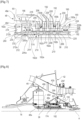
- FIG. 1 shows a turbomachine 10 which comprises, in a conventional manner, a fan 12, a low pressure (LP) compressor 14, a high pressure (HP) compressor 16, an annular combustion chamber 18, a high pressure (HP) turbine 20, a low pressure (LP) turbine 22 and an exhaust nozzle 24.
- a turbomachine 10 which comprises, in a conventional manner, a fan 12, a low pressure (LP) compressor 14, a high pressure (HP) compressor 16, an annular combustion chamber 18, a high pressure (HP) turbine 20, a low pressure (LP) turbine 22 and an exhaust nozzle 24.
- the rotors of the high-pressure compressor 16 and of the high-pressure turbine 20 are connected to each other by a high-pressure shaft 26 and form with it a high-pressure (HP) body which is guided in rotation about the longitudinal axis A of the turbomachine by rolling bearings 28, 30.
- a first bearing 28 is mounted between an upstream end of the shaft 26 and of the HP body and an inter-compressor casing 32 located between the LP 14 and HP 16 compressors.
- a second bearing 30 is mounted between a downstream end of shaft 26 and the HP body and an inter-turbine casing 34 located between the BP 22 and HP 20 turbines.
- the rotors of the BP compressor 14 and the BP turbine 22 are connected to each other by a low-pressure shaft 36 and form with it a low-pressure (BP) body which is guided in rotation about the longitudinal axis A of the turbomachine by rolling bearings 38, 40.
- At least one bearing 38 is mounted between an upstream end of the shaft 36 of the BP body and an inlet casing 42 located upstream of the BP compressor 14.
- Other bearings 40 are mounted between a downstream end of the shaft 36 of the BP body and an exhaust casing 44 located downstream of the BP turbine 22.
- the blower 12 is driven by a blower shaft 46 which is driven by the LP shaft 36 by means of a reducer 48.
- This reducer 48 is generally of the planetary or epicyclic type.
- the reducer 48 is positioned in the upstream part of the turbomachine.
- a fixed structure schematically comprising, here, an upstream part 50a and a downstream part 50b which composes the motor casing or stator 50 is arranged so as to form an enclosure E surrounding the reducer 48.
- This enclosure E is here closed upstream by a seal 52 at a bearing 54 allowing the fan shaft 46 to pass through, and downstream by a seal 55 at the bearing 38 allowing the LP shaft 36 to pass through.
- the enclosure E is arranged inside the inlet casing 42 which is located between an inlet rectifier blade 56 and the LP compressor 14.
- the reducer 48 comprises a solar 48a centered on the axis A and coupled to the BP shaft 36 for example by means of splines.
- the reducer 48 includes a crown 48b which is also centered on the axis A and fixed to the input housing 42.
- the reducer 48 finally comprises satellites 48c which are arranged around the axis A and meshed with the sun 48a and the ring 48b. These satellites 48c are carried by a planet carrier 48d which is rotatable around the axis A and is connected to the fan shaft 46 for its rotational drive.
- the planet carrier 48d is guided by bearings 58, 60 carried by the input casing 42, these bearings 58, 60 being located respectively upstream and downstream of the reducer 48.
- Blower 12 of the figure 1 comprises variable-pitch blades 12a and is associated with an actuator 62 which makes it possible to centrally control the positioning of the blades 12a around their axes B, which are generally radial axes relative to the axis A of the turbomachine.
- Each of the blades 12a comprises a foot 12b forming a pivot which is housed in a housing of a hub 64 in the form of a polygonal ring, and which is connected by a connection system 66 to a piston of the actuator 62.
- the actuator 62 extends along the axis A and its piston is movable in translation along this axis, for example from a first position in which the blades 12a are in a feathered position to a second position in which the blades 12a obstruct the passage of air through the fan 12.
- the air flow F1 which passes through the fan 12 is divided into two annular and coaxial flows downstream of the fan, by an annular separator 68 which extends around the blading 56.
- a first air flow called primary flow F2 flows in a primary vein and passes through this blading 56 and flows into the compressors 14 and 16 to be compressed. This compressed air is then mixed with fuel and then burned in the combustion chamber 18.
- the combustion gases are then expanded in the turbines 20, 22 to drive their rotors and the BP 36 and HP 26 shafts, then flow into the nozzle 24.
- a second air flow called secondary flow F3 flows in a secondary vein which is internally defined by an annular engine casing 70 which extends longitudinally around the compressors 14, 16, of the combustion chamber 18 and turbines 20, 22, and externally by an annular nacelle casing 72 which extends longitudinally around the fan 12 and a portion of the engine.
- This nacelle casing 72 is connected to the engine by outlet guide vanes 42a of the inlet casing 42. These guide vanes 42a are structural and are configured to straighten the air flow exiting the fan 12.
- the actuator 62 is hydraulic and operates with a fluid, oil, which comes from a lubrication system generally located in the nacelle or between the compressors 14, 16 and the casing 70 (i.e. in the engine) and therefore in a fixed reference frame of the turbomachine. On the contrary, the actuator 62 is located in a rotating reference frame.
- the turbomachine 10 comprises a device 74 for transferring oil from the fixed reference point of the engine to the rotating reference point in which the actuator 62 is located.
- the device 74 is located downstream of the reducer 48 and preferably comprises several oil supply paths 76 to supply the actuator 62 but also to lubricate the reducer 48.
- the dotted line of the figure 2 symbolizes one of these paths over its entire route, from the fixed reference point to the actuator 62: crossing the primary vein to the device 74, crossing the reducer 48 (between its satellites or through the axes of these satellites), and routing along the planet carrier then the fan shaft 46.
- FIGS. 3 to 5 illustrate an oil transfer device 74 according to the art prior to the present invention.
- the surface 82a of the shaft 82 comprises annular grooves 82c for housing annular sealing segments 84. These segments 84 are able to move in the grooves and are configured to bear radially on the internal surface 80a of the ring 80 to limit and control oil leaks.
- the outlets of the aforementioned pipes 80b, 82b are located between two adjacent segments 84 which therefore ensure that a maximum of oil supplied by each pipe 80b of the ring 80 supplies the corresponding pipe 82b of the shaft 82.
- the present invention makes it possible to remedy all or part of these problems thanks to an oil transfer device, one embodiment of which is illustrated in figures 6 And 7 .
- the oil transfer device 174 also comprises a stator ring 180 and a shaft 182 engaged in the stator ring 180 and rotatable about the axis A inside this ring 180.
- the ring 180 comprises an internal cylindrical surface 180a and internal oil pipes 180b which each open onto the surface 180a.
- the pipes 180b all have a radial orientation and are arranged one behind the other along the axis A. There are four of them in the example shown.
- the pipes 180b are here shown in the same axial plane, they could be located respectively in different axial planes. This depends in particular on the pipes 192 to which they are connected and on the arms 42b through which these pipes pass.
- the pipes 180b could comprise radially external ends located in the same axial plane and ends distributed angularly around the axis A and opening onto the surface 180a.
- Each of the pipes 180b comprises a radially inner end which forms the aforementioned outlet and a radially outer end which forms a port 190 for connection to an oil pipe 192.
- the port 190 forms a female part and one end of the pipe 192 forms a male part engaged in a sealed manner in the port 190.
- the pipes 192 connected to the ring 180 two are shown. These pipes 192 extend radially, first through openings 194 of an annular support 196 of the bearing 60, and secondly through tubular arms 42b of the inlet casing 42 which are located in the flow vein of the primary flow F2.
- the ring 180 has a generally cylindrical shape and comprises an upstream cylindrical rim 200a and a downstream cylindrical rim 200b. These rims 200a, 200b have identical or similar diameters.
- the ring 180 can be connected by an axial retaining device to a stator and for example to the bearing support 196.
- this device comprises a disk 202 located upstream of the ring 180 and extending radially outwards.
- This disk 202 has its external periphery which is engaged in an annular clamp 2020 carried by the bearing support 196.
- the disk 202 is able to slide in the circumferential direction inside the clamp 202a, and is in axial support upstream and downstream on the two jaws of this clamp 202a, located respectively upstream and downstream.
- the figure 7 shows that a hoop 204 can be fixed inside the ring 180 so as to define its surface 180a.
- This hoop 204 extends over a major part of the length of the ring 180 and comprises an annular rim 204a radially external to its upstream end which is in axial support on a cylindrical bearing surface of the ring 180. As its name indicates, the hoop 204 is mounted by hooping in the ring 180. The hooping associated with the support of its rim 204a ensures the immobilization of the hoop 204 with respect to the ring 180.
- the hoop 204 comprises an annular row of radial orifices 206 at right angles to each of the pipes 180b. Furthermore, an annular groove 208 is formed at the inner periphery of the ring 180 and at right angles to each of the pipes 180b, this groove 208 being closed on the inside by the hoop 204. It is therefore understood that each pipe 180b supplies a groove 208 and that each groove 208 distributes oil to the orifices 206 of the hoop 204.
- the shaft 182 comprises an external cylindrical surface 182a extending inside the surface 180a and internal oil channels 182b which each open onto the surface 182a.
- the channels 182b all have a radial orientation and are arranged one behind the other along the axis A. There are four of them in the example shown.
- An annular groove 210 is formed at the external periphery of the shaft 182 and at right angles to each of the channels 182b.
- Each of the pipes 182b is connected to a conduit 212 which can be integrated into the shaft 182.
- One of these conduits 212 visible in section in the figures, comprises an annular portion 212a which extends around the axis A and along a major part of the length of the shaft 182. The downstream end of this portion 212a is connected to the most downstream pipe 182b of the shaft, and its upstream end is connected to a radial portion 212b which is formed in an upstream annular rib 214 of the shaft.
- This rib 214 is used to fix the shaft 182 of the device 174.
- the shaft 182 of the device 174 is fixed to the planet carrier 48d of the reducer 48.
- the planet carrier 48d comprises a downstream cylindrical rim 48e on the external periphery of which the bearing 60 is mounted, and on the internal periphery of which the rib 214 is engaged.
- This rib 214 bears axially upstream on a cylindrical bearing surface of the rim 48e and is held in axial support against this bearing surface by a nut 216 screwed from downstream onto the internal periphery of the rim 48e.
- the bearing 60 is here a rolling bearing and comprises rollers which are arranged between two rings, respectively internal and external, the internal ring being clamped axially against another cylindrical bearing surface of the external periphery of the rim 48e by a nut 218 screwed from downstream onto this periphery.
- a first rolling bearing 220 is mounted between the rim 200b of the ring 180 and the downstream end of the shaft 182.
- the bearing 220 is here a rolling bearing and comprises rollers which are arranged between two rings, respectively internal 222 and external 224.
- the external ring 224 is mounted, preferably tightened in the radial direction, inside the rim 200b and is axially supported on a cylindrical bearing surface of the internal periphery of the rim 200b, located upstream. Downstream, the ring 224 is retained axially by a split annular ring 226 engaged in an annular groove of the internal periphery of the rim 200b.
- the inner ring 222 is mounted, preferably tightened in the radial direction, on the downstream end of the shaft 182 and is in axial support on a cylindrical bearing surface of the shaft, located upstream. Downstream, the ring 222 is retained axially by a hoop 228 fixed on the external periphery of the downstream end of the shaft 182.
- the rollers are preferably mounted tightened radially between the rings 222, 224.
- a second rolling bearing 230 is mounted between the flange 200a of the ring 180 and the shaft 182.
- the bearing 230 is here a rolling bearing and comprises rollers which are arranged between two rings, respectively internal 232 and external 234.
- the rollers are preferably mounted radially clamped between the rings 232, 234.
- the external ring 234 is mounted, preferably clamped in the radial direction, inside the rim 200a and is in axial support on a cylindrical bearing surface of the internal periphery of the rim 200a, located downstream.
- the ring 232 is, preferably clamped in the radial direction, and retained axially by a split annular ring 236 engaged in an annular groove of the internal periphery of the rim 200a.
- the inner ring 232 is mounted on a part of the shaft 182 located between the rib 214 and the pipes 182b. This ring 232 is in axial support on a cylindrical bearing surface of the shaft 182, located downstream. Upstream, the ring 232 is retained axially by an annular part 182c of the shaft which comprises the rib 214 and which is engaged on another part 182d of the shaft comprising the pipes 182b.
- the part 182c comprising the rib 214 is tightened axially against the inner ring 232 of the bearing 230 by a nut 260 screwed to the upstream end of the shaft 182 and in particular of the part 182d.
- shaft 182 comprises another annular part 182e which extends over the entire length of part 182d, inside the latter, and which defines conduit 212 with this part 182d.
- Part 182e carries a seal at each of its axial ends, which is intended to cooperate with the internal periphery of part 182d.
- the device 174 comprises two roller bearings 220, 230, there is no axial stop between the shaft 182 and the ring 180 of the device.
- the disc 202 and the clamp 202a described in the above ensure the axial retention of the ring 180 on the axially corresponding shaft 182.
- the BP shaft 36 thus forms the input shaft of the reducer 48.
- This shaft 36 has a diameter of between 30 mm and 200 mm, and preferably between 100 and 150 mm. It is configured to rotate at a peripheral speed of between 1 and 20 m/s, and preferably between 7 and 15 m/s.
- the surfaces 180a, 182a defined in the example represented by the hoop 204, on the one hand, and by the shaft 182, on the other hand, are spaced from each other by a radial thickness of between 10 and 30 ⁇ m.
- This space of controlled dimension allows the formation of a smooth bearing P between the shaft 182 and the ring 180, over substantially the entire longitudinal extent of the device 174.
- the device 174 is devoid of sealing members, and in particular of sealing segments, in this zone.
- the plain bearing P is supplied with oil directly by the pipes 180b of the ring 180. It is understood that the aforementioned radial thickness of the space is calculated so that controlled leaks occur at the interfaces between the pipes 180b, 182b, so as to supply the plain bearing P. The oil then spreads over the entire axial extent of the plain bearing P and up to the rolling bearings 220, 230 for their lubrication. The tight mounting of these bearings 220, 230 makes it possible on the one hand to guarantee the radial thickness of the space, without risk of misalignment of the shaft 182 and the ring 180, and on the other hand to limit oil leaks outside the plain bearing P.
- the leakage of a plain bearing is proportional to the diameter, the cube of the clearance and the square of the rotor/stator eccentricity (leakage calculation in a hydrostatic seal with annular section). Since the diameter of the plain bearing is relatively large and the operating pressure is also relatively high (e.g. 100-130 bar), it is therefore important to have a good understanding of the rotor/stator clearance and the rotor eccentricity during operation.
- the orifices 206 of the hoop 204 are located at an axial distance from each other and/or the grooves 210 of the shaft 182 are located at an axial distance from each other, between 15 and 35 mm.
- the rolling bearings 220, 230 preferably have identical average diameters. They are preferably identical.
- the average diameters of the bearings 220, 230 are preferably greater than the diameter of the bearing P.
- path of the device 174 is meant the association of a pipe 180b of the ring 180 with a pipe 182b of the shaft 182.
- the device 174 comprises four paths.
- one of the paths is used to lubricate the reducer 48, and in particular at least part of its bearings and teeth.
- One of the paths is used for the oil supply of the actuator 62, and another of the paths is used for the oil return of the actuator 62.
- the last path can be used for the hydraulic protection of the actuator.
- the pipes 212 connected to the actuator paths can pass through the planet carrier 48d of the reducer 48. Insofar as the shaft 182 of the device 174 and the pipes 212 are in the rotating frame of reference with the planet carrier 48d, the passage of the planet carrier 48d by these pipes 212 does not pose a problem.
- the device 174 is for example configured to supply the actuator 62 at an oil pressure of between 2 and 200 bars, and preferably between 5 and 130 bars, and to supply the reducer 48 at an oil pressure of between 2 and 50 bars, and preferably between 5 and 20 bars.
- Device 174 includes the features described in the foregoing except those which are in contradiction with the Figures 8 And 9 and what follows.
- the stator ring 180 comprises internal oil channels 180b which each comprise a radially internal end opening onto the surface 180a and a radially external end which forms a first port 190 for connection to an oil supply bushing 292.
- the port 190 forms a female portion and one end of the socket 292 forms a male portion sealingly engaged in the port 190.
- the port 190 and the socket 292 have an axial orientation so the socket 292 and the port 190 are engaged in each other by axial translation.
- the number of sockets 292 is for example equal to the number of pipes 180b.
- the bushings 292 have their axial ends opposite the ports 190 which are axially engaged in second ports of an annular support 250, as will be described in more detail in the following.
- the sockets 292 are of the “dog bone” type, that is to say they have a general dog bone shape. They each have an elongated shape with widened longitudinal ends which here carry sealing O-rings which cooperate with the ports 190.
- the ring 180 comprises an orifice 199' for mounting a temporary pin 199 for immobilizing the rotation of the ring 180 on the shaft 182.
- This pin 199 is configured to be engaged in a recess 199" of the aforementioned rim 48e of the turbomachine during the mounting of the device 174 and then to be removed after this mounting.
- the orifice 199' has a substantially radial orientation and is formed at the external periphery of the ring 180.
- the recess 199" is formed by a notch formed on the free downstream edge of the rim 48e.
- the pin 199 comprises a cylindrical body oriented radially in the mounting position, and connected to a head comprising a through hole for attaching one end of a cable (not shown). This cable is used by an operator to pull on the pin 199, disengage it from the hole 199' and the recess 199' and remove it from the turbomachine.
- the head is connected to the radially outer end of the body when the pin 199 is in the mounting position.
- the annular support 250 extends at least partly around the ring 180 and carries the sleeves 292 for fluid connection to the pipes 180b of the ring 180.
- the support 250 comprises several annular walls and members for fixing to the casing 42, which are formed in the example shown by annular flanges 252, 254.
- the support 250 is preferably configured to deform elastically so as to allow movements of the bearing 60 in the radial direction. This support 250 is independent of the ring 180 insofar as they are not rigidly fixed to each other.
- the support 250 comprises truncated cone-shaped walls 256, 258, at least one of which may be perforated, i.e. may comprise through-holes, so as to reduce its rigidity in the radial direction. This rigidity may also be reduced by reducing the thickness of this wall.
- a first truncated cone-shaped wall 256 of the support 250 extends substantially radially and is connected at its external periphery to the flange 252 for fixing to the casing 42. At its internal periphery, this wall 256 comprises integrated pipes 290 comprising ports 293, 294 at each of its ends.
- the number of pipes 290 is equal to the number of pipes 180b of the ring 180. Only one of these pipes 290 is visible at Figures 8 And 9 .
- Each of the pipes 290 has a bent shape, one radially inner end of which is connected to the port 293 which extends axially upstream opposite one of the aforementioned ports 190, in order to receive by male-female engagement one end of a socket 292 engaged in this port 190.
- the radially outer end of each pipe 290 is connected to the port 294 which extends radially upstream opposite one of the aforementioned ports 190, in order to receive by male-female engagement one end of a socket 292 engaged in this port 190. upstream and outwards to receive by male-female engagement the radially internal end of an oil supply pipe 296.
- the support 250 comprises a second frustoconical wall 258 which extends radially outward from upstream to downstream.
- This second wall 258 comprises at its external periphery the flange 254 for fixing to the casing 42.
- the flange 254' of the casing 42 which is fixed to the flanges 252, 254, extends in a plane perpendicular to the axis A, which passes between the bearings 220, 230.
- the inner periphery of the wall 258 is located upstream of the ring 180 and carries the outer ring of the aforementioned bearing 60 in the example shown.
- the support 250 and in particular its wall 258 comprises openings 270 for the passage of the oil supply pipes 296.
- Each of the pipes 296 extends radially, first through the openings 270, and secondly through tubular arms 42b of the inlet casing 42 which are located in the flow vein of the primary flow F2. These pipes 296 will then pass through the guide vanes 42a which are located in the flow vein of the secondary flow F3, to join the lubrication system located in the nacelle (see figure 1 ).
- An alternative is to mount the lubrication system in the engine (between the primary flow - compressors 14 and 16) and the casing 70 of the secondary flow, so that these lines 192 do not cross the secondary flow F3.
- the device 174 is then in the form of a pre-assembled cartridge.
- the ring 180 is mounted in a slave manner on the shaft 182 which makes it possible to control and guarantee the play of the plain bearing P.
Landscapes
- Engineering & Computer Science (AREA)
- General Engineering & Computer Science (AREA)
- Mechanical Engineering (AREA)
- Chemical & Material Sciences (AREA)
- Combustion & Propulsion (AREA)
- General Details Of Gearings (AREA)
- Structures Of Non-Positive Displacement Pumps (AREA)
Claims (11)
- Gebläsemodul für ein Turbotriebwerk eines Luftfahrzeugs, wobei dieses Modul ein Gebläse (12) umfasst, das eine Gebläsewelle (46) und Gebläseschaufeln (12a) mit variabler Feststellposition und eine Vorrichtung (174) zum Transferieren von Öl umfasst, die konfiguriert ist, um einen Transfer von Öl zwischen einem Stator und einem Aktuator (62) sicherzustellen, der mit der Gebläsewelle (46) drehfest ist und der konfiguriert ist, um die Feststellposition der Gebläseschaufeln zu steuern, wobei diese Vorrichtung umfasst:- einen Statorring (180), umfassend eine interne zylindrische Oberfläche (180a) und interne Ölkanäle (180b), die jeweils auf der internen zylindrischen Oberfläche münden,- eine in dem Statorring in Eingriff stehende und um eine Achse (A) im Inneren dieses Rings herum drehbewegliche Welle (182), wobei die Welle (182) eine externe zylindrische Oberfläche (182a) umfasst, die sich im Inneren der internen zylindrischen Oberfläche (180a) erstreckt, wobei die Welle (182) interne Ölkanäle (182b) umfasst, die jeweils auf der externen zylindrischen Oberfläche (182a) münden,dadurch gekennzeichnet, dass die interne und externe zylindrische Oberfläche (180a, 182a) zwischen ihnen einen ringförmigen Raum definieren, der eine radiale Dicke zwischen 10 und 30 µm zur Bildung eines Gleitlagers (P) definiert, wobei dieses Gleitlager sich über die gesamte axiale Erstreckung dieser Oberflächen (180a, 182a) erstreckt und frei von Dichtungselementen ist,und dadurch, dass zwei Wälzlager (220, 230) zwischen dem Ring (180) und der Welle (182) montiert sind, ein Wälzlager (220, 230) an jeder Seite des Gleitlagers (P), wobei jedes Wälzlager zwei Dichtungsringe (222, 224, 232, 234) umfasst, zwischen denen sich die Wälzkörper befinden, wobei jedes Wälzlager in radialer Richtung zwischen dem Ring und der Welle straff montiert ist.
- Gebläsemodul nach Anspruch 1, wobei die Wälzlager (220, 230) mit Rollen sind.
- Gebläsemodul nach einem der vorstehenden Ansprüche, wobei die Welle (182) und der Ring (180) jeweils mindestens drei oder vier Kanäle (180b, 182b) umfassen, die entlang der Achse (A) hintereinander ausgerichtet sind.
- Gebläsemodul nach einem der vorstehenden Ansprüche, wobei jeder der Kanäle (180b, 182b) in einer ringförmigen Nut (208, 210) mündet, die sich auf der internen oder externen zylindrischen Oberfläche (180a, 182a) befindet.
- Gebläsemodul nach dem vorstehenden Anspruch, wobei die Öffnungen oder die Nuten (208, 210) sich in einem axialen Abstand zwischen 15 und 35 mm voneinander befinden.
- Gebläsemodul nach einem der vorstehenden Ansprüche, wobei ein Schrumpfring (204) im Inneren des Rings (180) montiert ist und die interne Oberfläche (180a) definiert.
- Gebläsemodul nach einem der vorstehenden Ansprüche, wobei die Wälzlager (220, 230) identische mittlere Durchmesser aufweisen.
- Gebläsemodul nach einem der vorstehenden Ansprüche, wobei die Wälzlager (220, 230) größere mittlere Durchmesser aufweisen als der Durchmesser des Gleitlagers (P).
- Gebläsemodul nach Anspruch 4, wobei die Dichtungsringe (222, 224, 232, 234) der Wälzlager (220, 230) identische interne Durchmesser aufweisen.
- Gebläsemodul nach einem der vorstehenden Ansprüche, wobei das Gebläse (12) durch ein Getriebe (48) in Drehung versetzt wird, wobei die Vorrichtung (174) dem Getriebe nachgelagert montiert ist und konfiguriert ist, um dem Getriebe (48) sowie dem Aktuator durch die Leitungen (212), die das Getriebe durchqueren, Öl zuzuführen.
- Verfahren zum Zusammenbau eines Gebläsemoduls nach dem vorstehenden Anspruch, beinhaltend die Schritte:a) Montage des Rings (180) auf der Welle (182) der Vorrichtung (174),b) Befestigung der Welle (182) der Vorrichtung (174) an einem Satelittenträger (48d) des Getriebes (48) undd) translatorische Verschiebung des Getriebes (48) und der Vorrichtung (174) in Richtung des Stators.
Applications Claiming Priority (2)
| Application Number | Priority Date | Filing Date | Title |
|---|---|---|---|
| FR2102621A FR3120913B1 (fr) | 2021-03-16 | 2021-03-16 | Module de soufflante equipe d’un dispositif de transfert d’huile |
| PCT/FR2022/050426 WO2022195199A1 (fr) | 2021-03-16 | 2022-03-09 | Module de soufflante equipe d'un dispositif de transfert d'huile |
Publications (2)
| Publication Number | Publication Date |
|---|---|
| EP4308796A1 EP4308796A1 (de) | 2024-01-24 |
| EP4308796B1 true EP4308796B1 (de) | 2024-10-02 |
Family
ID=75690528
Family Applications (1)
| Application Number | Title | Priority Date | Filing Date |
|---|---|---|---|
| EP22713709.8A Active EP4308796B1 (de) | 2021-03-16 | 2022-03-09 | Fanmodul ausgestattet mit öltransfervorrichtung |
Country Status (5)
| Country | Link |
|---|---|
| US (1) | US12092029B2 (de) |
| EP (1) | EP4308796B1 (de) |
| CN (1) | CN116964298A (de) |
| FR (1) | FR3120913B1 (de) |
| WO (1) | WO2022195199A1 (de) |
Citations (3)
| Publication number | Priority date | Publication date | Assignee | Title |
|---|---|---|---|---|
| US8484942B1 (en) * | 2012-05-30 | 2013-07-16 | United Technologies Corporation | Planetary gear system arrangement with auxiliary oil system |
| EP3070377A1 (de) * | 2015-03-19 | 2016-09-21 | United Technologies Corporation | Ölübertragungslager ohne leckagen oder mit geringen leckagen |
| WO2020074816A1 (fr) * | 2018-10-12 | 2020-04-16 | Safran Aircraft Engines | Turbomachine comprenant un rotor portant des pales a calage variable |
Family Cites Families (8)
| Publication number | Priority date | Publication date | Assignee | Title |
|---|---|---|---|---|
| GB824332A (en) | 1956-07-17 | 1959-11-25 | Rolls Royce | Improvements in or relating to airscrew-driving gas-turbine engines |
| US6758598B2 (en) * | 2002-08-23 | 2004-07-06 | Pratt & Whitney Canada Corp. | Integrated oil transfer sleeve and bearing |
| CA2740452A1 (en) * | 2010-05-18 | 2011-11-18 | Hamilton Sundstrand Corporation | Counter-rotating open-rotor (cror) |
| FR2978122B1 (fr) * | 2011-07-21 | 2013-08-30 | Snecma | Dispositif d'alimentation en fluide d'un verin hydraulique pour la commande de l'orientation des pales de soufflante d'un turbopropulseur a double helice |
| EP3792472B1 (de) * | 2013-12-30 | 2022-04-13 | Raytheon Technologies Corporation | Gasturbinentriebwerk mit fanantriebgetriebesystem mit einer zweiteiligen fanwelle mit auffang von schmiermitteltransferleckage |
| PL226824B1 (pl) * | 2015-09-07 | 2017-09-29 | Gen Electric | Układ isposób regulacji skoku smigła |
| US20170167507A1 (en) * | 2015-12-09 | 2017-06-15 | General Electric Company | Method and system for a pitch change mechanism hydraulic fluid transfer sleeve |
| FR3120651B1 (fr) * | 2021-03-09 | 2023-05-12 | Safran Aircraft Engines | Dispositif de calage de pas de pales pour turbomachine et turbomachine le comportant |
-
2021
- 2021-03-16 FR FR2102621A patent/FR3120913B1/fr active Active
-
2022
- 2022-03-09 US US18/549,681 patent/US12092029B2/en active Active
- 2022-03-09 EP EP22713709.8A patent/EP4308796B1/de active Active
- 2022-03-09 WO PCT/FR2022/050426 patent/WO2022195199A1/fr not_active Ceased
- 2022-03-09 CN CN202280020762.0A patent/CN116964298A/zh active Pending
Patent Citations (3)
| Publication number | Priority date | Publication date | Assignee | Title |
|---|---|---|---|---|
| US8484942B1 (en) * | 2012-05-30 | 2013-07-16 | United Technologies Corporation | Planetary gear system arrangement with auxiliary oil system |
| EP3070377A1 (de) * | 2015-03-19 | 2016-09-21 | United Technologies Corporation | Ölübertragungslager ohne leckagen oder mit geringen leckagen |
| WO2020074816A1 (fr) * | 2018-10-12 | 2020-04-16 | Safran Aircraft Engines | Turbomachine comprenant un rotor portant des pales a calage variable |
Also Published As
| Publication number | Publication date |
|---|---|
| FR3120913B1 (fr) | 2023-02-24 |
| US20240167421A1 (en) | 2024-05-23 |
| CN116964298A (zh) | 2023-10-27 |
| FR3120913A1 (fr) | 2022-09-23 |
| US12092029B2 (en) | 2024-09-17 |
| WO2022195199A1 (fr) | 2022-09-22 |
| EP4308796A1 (de) | 2024-01-24 |
Similar Documents
| Publication | Publication Date | Title |
|---|---|---|
| EP4452751A1 (de) | Turbomaschinenmodul mit schaufeln mit verstellbarem blattabstand und mit einer ölübertragungsvorrichtung | |
| EP4308794B1 (de) | Fanmodul ausgestattet mit einer öltransfervorrichtung | |
| EP3705705B1 (de) | Mechanisches reduktionsgetriebe für luftfahrzeug-turbotriebwerk | |
| EP3649373B1 (de) | Zahnkranz für ein epizyklisches- oder planetenuntersetzungsgetriebe einer turbomaschine | |
| EP3956555B1 (de) | Reduktionsgetriebe einer turbomaschine | |
| EP3158210A1 (de) | Vorrichtung und verfahren zum schmieren des wälzlagers einer turbomaschine | |
| EP3740657B1 (de) | Ölsammler für ein untersetzungsgetriebe, insbesondere einer turbomaschine sowie zugehöriges untersetzungsgetriebe und turbomaschine | |
| EP3682139A1 (de) | Drehzapfen für ein gleitlager | |
| EP4240951B1 (de) | Modularität einer flugzeugturbomaschine | |
| EP3763932A1 (de) | Mechanisches reduktionsgetriebe für turbotriebwerk eines luftfahrzeugs | |
| WO2022195191A1 (fr) | Module de soufflante equipe d'un dispositif de transfert d'huile | |
| EP4023909B1 (de) | Satellitenträger für ein reduktionsgetriebe für luftfahrzeug-turbotriebwerk | |
| EP4056829B1 (de) | Kühlung von zahnrädern eines untersetzungsgetriebes eines turbinentriebwerks | |
| EP4308796B1 (de) | Fanmodul ausgestattet mit öltransfervorrichtung | |
| EP3682138A1 (de) | Drehzapfen für ein gleitlager | |
| EP4308795A1 (de) | Lüftermodul mit ölübertragungsvorrichtung | |
| EP4208633B1 (de) | Anordnung für ein flugzeugturbinentriebwerk mit mitteln zur axialen und radialen halterung eines lüfters | |
| EP4118306B1 (de) | Turbomaschinenmodul mit einem rotor einer elektrischen maschine | |
| EP4123190B1 (de) | Mechanisches untersetzungsgetriebe für gasturbomaschinen mit längsachse | |
| FR3164752A1 (fr) | Reducteur pour turbomachine d’aeronef et turbomachine equipee d’un tel reducteur | |
| WO2025083376A1 (fr) | Dispositif de transfert fluidique multivoies a partie peripherique pourvue d'une frette, d'un manchon et de bagues definissant conjointement des chemins fluidiques | |
| WO2025083374A1 (fr) | Dispositif comprenant un palier a support frangible et encombrement limite, et procédé de mise en oeuvre dudit dispositif | |
| WO2025083375A1 (fr) | Dispositif de transfert fluidique multivoies comprenant des bagues contribuant à définir une surface interne de partie périphérique | |
| WO2025083373A1 (fr) | Dispositif de transfert fluidique multivoies à partie centrale pourvue de canaux concentriques | |
| FR3137131A1 (fr) | Module de turbomachine équipé d’un raccord fluidique |
Legal Events
| Date | Code | Title | Description |
|---|---|---|---|
| STAA | Information on the status of an ep patent application or granted ep patent |
Free format text: STATUS: UNKNOWN |
|
| STAA | Information on the status of an ep patent application or granted ep patent |
Free format text: STATUS: THE INTERNATIONAL PUBLICATION HAS BEEN MADE |
|
| PUAI | Public reference made under article 153(3) epc to a published international application that has entered the european phase |
Free format text: ORIGINAL CODE: 0009012 |
|
| STAA | Information on the status of an ep patent application or granted ep patent |
Free format text: STATUS: REQUEST FOR EXAMINATION WAS MADE |
|
| 17P | Request for examination filed |
Effective date: 20230912 |
|
| AK | Designated contracting states |
Kind code of ref document: A1 Designated state(s): AL AT BE BG CH CY CZ DE DK EE ES FI FR GB GR HR HU IE IS IT LI LT LU LV MC MK MT NL NO PL PT RO RS SE SI SK SM TR |
|
| DAV | Request for validation of the european patent (deleted) | ||
| DAX | Request for extension of the european patent (deleted) | ||
| GRAP | Despatch of communication of intention to grant a patent |
Free format text: ORIGINAL CODE: EPIDOSNIGR1 |
|
| STAA | Information on the status of an ep patent application or granted ep patent |
Free format text: STATUS: GRANT OF PATENT IS INTENDED |
|
| GRAS | Grant fee paid |
Free format text: ORIGINAL CODE: EPIDOSNIGR3 |
|
| INTG | Intention to grant announced |
Effective date: 20240730 |
|
| GRAA | (expected) grant |
Free format text: ORIGINAL CODE: 0009210 |
|
| STAA | Information on the status of an ep patent application or granted ep patent |
Free format text: STATUS: THE PATENT HAS BEEN GRANTED |
|
| AK | Designated contracting states |
Kind code of ref document: B1 Designated state(s): AL AT BE BG CH CY CZ DE DK EE ES FI FR GB GR HR HU IE IS IT LI LT LU LV MC MK MT NL NO PL PT RO RS SE SI SK SM TR |
|
| REG | Reference to a national code |
Ref country code: GB Ref legal event code: FG4D Free format text: NOT ENGLISH |
|
| REG | Reference to a national code |
Ref country code: CH Ref legal event code: EP |
|
| REG | Reference to a national code |
Ref country code: DE Ref legal event code: R096 Ref document number: 602022006524 Country of ref document: DE |
|
| REG | Reference to a national code |
Ref country code: IE Ref legal event code: FG4D Free format text: LANGUAGE OF EP DOCUMENT: FRENCH |
|
| REG | Reference to a national code |
Ref country code: LT Ref legal event code: MG9D |
|
| REG | Reference to a national code |
Ref country code: NL Ref legal event code: MP Effective date: 20241002 |
|
| REG | Reference to a national code |
Ref country code: AT Ref legal event code: MK05 Ref document number: 1728652 Country of ref document: AT Kind code of ref document: T Effective date: 20241002 |
|
| PG25 | Lapsed in a contracting state [announced via postgrant information from national office to epo] |
Ref country code: NL Free format text: LAPSE BECAUSE OF FAILURE TO SUBMIT A TRANSLATION OF THE DESCRIPTION OR TO PAY THE FEE WITHIN THE PRESCRIBED TIME-LIMIT Effective date: 20241002 |
|
| PG25 | Lapsed in a contracting state [announced via postgrant information from national office to epo] |
Ref country code: NL Free format text: LAPSE BECAUSE OF FAILURE TO SUBMIT A TRANSLATION OF THE DESCRIPTION OR TO PAY THE FEE WITHIN THE PRESCRIBED TIME-LIMIT Effective date: 20241002 |
|
| PG25 | Lapsed in a contracting state [announced via postgrant information from national office to epo] |
Ref country code: HR Free format text: LAPSE BECAUSE OF FAILURE TO SUBMIT A TRANSLATION OF THE DESCRIPTION OR TO PAY THE FEE WITHIN THE PRESCRIBED TIME-LIMIT Effective date: 20241002 Ref country code: IS Free format text: LAPSE BECAUSE OF FAILURE TO SUBMIT A TRANSLATION OF THE DESCRIPTION OR TO PAY THE FEE WITHIN THE PRESCRIBED TIME-LIMIT Effective date: 20250202 Ref country code: PT Free format text: LAPSE BECAUSE OF FAILURE TO SUBMIT A TRANSLATION OF THE DESCRIPTION OR TO PAY THE FEE WITHIN THE PRESCRIBED TIME-LIMIT Effective date: 20250203 |
|
| PGFP | Annual fee paid to national office [announced via postgrant information from national office to epo] |
Ref country code: DE Payment date: 20250218 Year of fee payment: 4 |
|
| PG25 | Lapsed in a contracting state [announced via postgrant information from national office to epo] |
Ref country code: FI Free format text: LAPSE BECAUSE OF FAILURE TO SUBMIT A TRANSLATION OF THE DESCRIPTION OR TO PAY THE FEE WITHIN THE PRESCRIBED TIME-LIMIT Effective date: 20241002 |
|
| PG25 | Lapsed in a contracting state [announced via postgrant information from national office to epo] |
Ref country code: BG Free format text: LAPSE BECAUSE OF FAILURE TO SUBMIT A TRANSLATION OF THE DESCRIPTION OR TO PAY THE FEE WITHIN THE PRESCRIBED TIME-LIMIT Effective date: 20241002 |
|
| PG25 | Lapsed in a contracting state [announced via postgrant information from national office to epo] |
Ref country code: ES Free format text: LAPSE BECAUSE OF FAILURE TO SUBMIT A TRANSLATION OF THE DESCRIPTION OR TO PAY THE FEE WITHIN THE PRESCRIBED TIME-LIMIT Effective date: 20241002 |
|
| PG25 | Lapsed in a contracting state [announced via postgrant information from national office to epo] |
Ref country code: NO Free format text: LAPSE BECAUSE OF FAILURE TO SUBMIT A TRANSLATION OF THE DESCRIPTION OR TO PAY THE FEE WITHIN THE PRESCRIBED TIME-LIMIT Effective date: 20250102 |
|
| PG25 | Lapsed in a contracting state [announced via postgrant information from national office to epo] |
Ref country code: GR Free format text: LAPSE BECAUSE OF FAILURE TO SUBMIT A TRANSLATION OF THE DESCRIPTION OR TO PAY THE FEE WITHIN THE PRESCRIBED TIME-LIMIT Effective date: 20250103 Ref country code: AT Free format text: LAPSE BECAUSE OF FAILURE TO SUBMIT A TRANSLATION OF THE DESCRIPTION OR TO PAY THE FEE WITHIN THE PRESCRIBED TIME-LIMIT Effective date: 20241002 Ref country code: LV Free format text: LAPSE BECAUSE OF FAILURE TO SUBMIT A TRANSLATION OF THE DESCRIPTION OR TO PAY THE FEE WITHIN THE PRESCRIBED TIME-LIMIT Effective date: 20241002 |
|
| PG25 | Lapsed in a contracting state [announced via postgrant information from national office to epo] |
Ref country code: PL Free format text: LAPSE BECAUSE OF FAILURE TO SUBMIT A TRANSLATION OF THE DESCRIPTION OR TO PAY THE FEE WITHIN THE PRESCRIBED TIME-LIMIT Effective date: 20241002 Ref country code: CZ Free format text: LAPSE BECAUSE OF FAILURE TO SUBMIT A TRANSLATION OF THE DESCRIPTION OR TO PAY THE FEE WITHIN THE PRESCRIBED TIME-LIMIT Effective date: 20241002 |
|
| PGFP | Annual fee paid to national office [announced via postgrant information from national office to epo] |
Ref country code: FR Payment date: 20250218 Year of fee payment: 4 |
|
| PG25 | Lapsed in a contracting state [announced via postgrant information from national office to epo] |
Ref country code: RS Free format text: LAPSE BECAUSE OF FAILURE TO SUBMIT A TRANSLATION OF THE DESCRIPTION OR TO PAY THE FEE WITHIN THE PRESCRIBED TIME-LIMIT Effective date: 20250102 |
|
| PG25 | Lapsed in a contracting state [announced via postgrant information from national office to epo] |
Ref country code: SM Free format text: LAPSE BECAUSE OF FAILURE TO SUBMIT A TRANSLATION OF THE DESCRIPTION OR TO PAY THE FEE WITHIN THE PRESCRIBED TIME-LIMIT Effective date: 20241002 |
|
| REG | Reference to a national code |
Ref country code: DE Ref legal event code: R097 Ref document number: 602022006524 Country of ref document: DE |
|
| PG25 | Lapsed in a contracting state [announced via postgrant information from national office to epo] |
Ref country code: DK Free format text: LAPSE BECAUSE OF FAILURE TO SUBMIT A TRANSLATION OF THE DESCRIPTION OR TO PAY THE FEE WITHIN THE PRESCRIBED TIME-LIMIT Effective date: 20241002 |
|
| PG25 | Lapsed in a contracting state [announced via postgrant information from national office to epo] |
Ref country code: EE Free format text: LAPSE BECAUSE OF FAILURE TO SUBMIT A TRANSLATION OF THE DESCRIPTION OR TO PAY THE FEE WITHIN THE PRESCRIBED TIME-LIMIT Effective date: 20241002 |
|
| PG25 | Lapsed in a contracting state [announced via postgrant information from national office to epo] |
Ref country code: RO Free format text: LAPSE BECAUSE OF FAILURE TO SUBMIT A TRANSLATION OF THE DESCRIPTION OR TO PAY THE FEE WITHIN THE PRESCRIBED TIME-LIMIT Effective date: 20241002 |
|
| PG25 | Lapsed in a contracting state [announced via postgrant information from national office to epo] |
Ref country code: SK Free format text: LAPSE BECAUSE OF FAILURE TO SUBMIT A TRANSLATION OF THE DESCRIPTION OR TO PAY THE FEE WITHIN THE PRESCRIBED TIME-LIMIT Effective date: 20241002 |
|
| PG25 | Lapsed in a contracting state [announced via postgrant information from national office to epo] |
Ref country code: IT Free format text: LAPSE BECAUSE OF FAILURE TO SUBMIT A TRANSLATION OF THE DESCRIPTION OR TO PAY THE FEE WITHIN THE PRESCRIBED TIME-LIMIT Effective date: 20241002 |
|
| PLBE | No opposition filed within time limit |
Free format text: ORIGINAL CODE: 0009261 |
|
| STAA | Information on the status of an ep patent application or granted ep patent |
Free format text: STATUS: NO OPPOSITION FILED WITHIN TIME LIMIT |
|
| PG25 | Lapsed in a contracting state [announced via postgrant information from national office to epo] |
Ref country code: SE Free format text: LAPSE BECAUSE OF FAILURE TO SUBMIT A TRANSLATION OF THE DESCRIPTION OR TO PAY THE FEE WITHIN THE PRESCRIBED TIME-LIMIT Effective date: 20241002 |
|
| 26N | No opposition filed |
Effective date: 20250703 |
|
| PG25 | Lapsed in a contracting state [announced via postgrant information from national office to epo] |
Ref country code: MC Free format text: LAPSE BECAUSE OF FAILURE TO SUBMIT A TRANSLATION OF THE DESCRIPTION OR TO PAY THE FEE WITHIN THE PRESCRIBED TIME-LIMIT Effective date: 20241002 |
|
| REG | Reference to a national code |
Ref country code: CH Ref legal event code: H13 Free format text: ST27 STATUS EVENT CODE: U-0-0-H10-H13 (AS PROVIDED BY THE NATIONAL OFFICE) Effective date: 20251023 |
|
| PG25 | Lapsed in a contracting state [announced via postgrant information from national office to epo] |
Ref country code: LU Free format text: LAPSE BECAUSE OF NON-PAYMENT OF DUE FEES Effective date: 20250309 |
|
| REG | Reference to a national code |
Ref country code: BE Ref legal event code: MM Effective date: 20250331 |
|
| PG25 | Lapsed in a contracting state [announced via postgrant information from national office to epo] |
Ref country code: BE Free format text: LAPSE BECAUSE OF NON-PAYMENT OF DUE FEES Effective date: 20250331 |
|
| PG25 | Lapsed in a contracting state [announced via postgrant information from national office to epo] |
Ref country code: CH Free format text: LAPSE BECAUSE OF NON-PAYMENT OF DUE FEES Effective date: 20250331 |
|
| PG25 | Lapsed in a contracting state [announced via postgrant information from national office to epo] |
Ref country code: IE Free format text: LAPSE BECAUSE OF NON-PAYMENT OF DUE FEES Effective date: 20250309 |