EP4308435B1 - Stroller - Google Patents
Stroller Download PDFInfo
- Publication number
- EP4308435B1 EP4308435B1 EP22733959.5A EP22733959A EP4308435B1 EP 4308435 B1 EP4308435 B1 EP 4308435B1 EP 22733959 A EP22733959 A EP 22733959A EP 4308435 B1 EP4308435 B1 EP 4308435B1
- Authority
- EP
- European Patent Office
- Prior art keywords
- seat
- stroller
- fixing base
- engaging members
- unlock button
- Prior art date
- Legal status (The legal status is an assumption and is not a legal conclusion. Google has not performed a legal analysis and makes no representation as to the accuracy of the status listed.)
- Active
Links
Images


Classifications
-
- B—PERFORMING OPERATIONS; TRANSPORTING
- B62—LAND VEHICLES FOR TRAVELLING OTHERWISE THAN ON RAILS
- B62B—HAND-PROPELLED VEHICLES, e.g. HAND CARTS OR PERAMBULATORS; SLEDGES
- B62B7/00—Carriages for children; Perambulators, e.g. dolls' perambulators
- B62B7/04—Carriages for children; Perambulators, e.g. dolls' perambulators having more than one wheel axis; Steering devices therefor
- B62B7/14—Carriages for children; Perambulators, e.g. dolls' perambulators having more than one wheel axis; Steering devices therefor with detachable or rotatably-mounted body
- B62B7/142—Means for securing the body to the frame
-
- B—PERFORMING OPERATIONS; TRANSPORTING
- B62—LAND VEHICLES FOR TRAVELLING OTHERWISE THAN ON RAILS
- B62B—HAND-PROPELLED VEHICLES, e.g. HAND CARTS OR PERAMBULATORS; SLEDGES
- B62B9/00—Accessories or details specially adapted for children's carriages or perambulators
- B62B9/10—Perambulator bodies; Equipment therefor
- B62B9/12—Perambulator bodies; Equipment therefor involving parts that are adjustable, attachable or detachable
Definitions
- the present invention relates to a stroller, particularly a stroller with a seat capable of being detached conveniently.
- a stroller is a tool used by parents to carry babies or children when they go shopping.
- a seat of a conventional stroller is detachable to facilitate storage or transportation.
- a detachable structure of the conventional seat is complicated and a user usually needs to use both hands to remove the seat.
- the engaging structure is a ring-shaped recess and the engaging members engage with the ring-shaped recess to rotatably restrain the seat on the seat fixing base.
- the seat further includes a plurality of first elastic members and a pillar, the engaging members surround the pillar, and opposite ends of each of the first elastic members abut against a corresponding one of the engaging members and the pillar respectively.
- the seat fixing base has a protrusion and the pillar has a groove.
- the protrusion is inserted into the groove.
- the unlock button has a guiding groove
- the pillar has a guiding portion
- the guiding portion is inserted into the guiding groove
- the unlock button has a first inclined surface
- each of the engaging members has a second inclined surface
- the first inclined surface abuts against the second inclined surface of each of the engaging members.
- the first inclined surface pushes the second inclined surface of each of the engaging members to drive each of the engaging members to disengage from the engaging structure.
- the seat fixing base has two positioning recesses and the seat further includes a positioning member.
- the seat When the positioning member engages with one of the two positioning recesses, the seat faces a front direction of the stroller.
- the positioning member engages with the other one of the two positioning recesses, the seat faces a rear direction of the stroller.
- the seat further includes a second elastic member and opposite ends of the second elastic member abut against the positioning member and the seat.
- the seat further includes a webbing and the webbing is disposed on an upper surface of the seat.
- a moving direction of each of the engaging members is perpendicular to a pressing direction of the unlock button.
- the frame of the invention is equipped with the seat fixing base with the engaging structure.
- the engaging members of the seat engage with the engaging structure of the seat fixing base
- the seat is restrained on the seat fixing base.
- a user may press the unlock button by one hand.
- the unlock button drives the engaging members to disengage from the engaging structure, such that the seat is able to be detached from the seat fixing base.
- the invention may dispose the webbing on the upper surface of the seat.
- the user may press the unlock button of the seat by a thumb and pull the webbing upward by other fingers, so as to detach the seat from the seat fixing base. Accordingly, the user may detach the seat by one hand.
- the operation is convenient and the structure is simple.
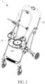
- FIG. 1 is a perspective view illustrating a stroller 1 according to an embodiment of the invention
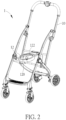
- FIG. 2 is a perspective view illustrating the stroller 1 shown in FIG. 1 without a seat 14
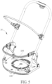
- FIG. 3 is a perspective view illustrating the seat 14 shown in FIG. 1 from another viewing angle
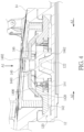
- FIG. 4 is a sectional view illustrating an assembly of the seat 14 and a seat fixing base 12.
- the stroller 1 includes a frame 10, a seat fixing base 12 and a seat 14.
- the seat fixing base 12 is disposed on the frame 10 and the seat 14 is detachably disposed on the seat fixing base 12.
- the seat fixing base 12 has an engaging structure 120.
- the seat 14 includes an unlock button 140 and a plurality of engaging members 142, wherein the unlock button 140 abuts against the engaging members 142.
- the seat 14 may include four engaging members 142, but the invention is not so limited. The number of the engaging members 142 may be determined according to practical applications.
- the engaging members 142 engage with the engaging structure 120 to restrain the seat 14 on the seat fixing base 12.
- the user may press the unlock button 140 in a direction of an arrow A1.
- the unlock button 140 drives the engaging members 142 to move in a direction of an arrow A2.
- the engaging members 142 disengage from the engaging structure 120, such that the seat 14 is able to be detached from the seat fixing base 12.
- a moving direction of each of the engaging members 142 i.e. the direction of the arrow A2 is perpendicular to a pressing direction of the unlock button 140 (i.e. the direction of the arrow A1), but the invention is not so limited.
- the engaging structure 120 of the seat fixing base 12 is a ring-shaped recess.
- the engaging members 142 engage with the ring-shaped recess (i.e. the engaging structure 120) to rotatably restrain the seat 14 on the seat fixing base 12.
- the engaging members 142 may freely move within the ring-shaped recess, such that the seat 14 may rotate 360 degrees with respect to the seat fixing base 12.
- the engaging members 142 engage with the engaging structure 120, the seat 14 is restrained on the seat fixing base 12 while rotating, such that the seat 14 will rotate more stable.
- the seat 14 may further include a plurality of first elastic members 144 and a pillar 146.
- the engaging members 142 surround the pillar 146.
- opposite ends of each of the first elastic members 144 abut against a corresponding one of the engaging members 142 and the pillar 146 respectively.
- the unlock button 140 may have a first inclined surface 1400 and each of the engaging members 142 may have a second inclined surface 1420, wherein the first inclined surface 1400 abuts against the second inclined surface 1420 of each of the engaging members 142.
- the first inclined surface 1400 of the unlock button 140 pushes the second inclined surface 1420 of each of the engaging members 142, so as to drive each of the engaging members 142 to move in the direction of the arrow A2 to disengage from the engaging structure 120 of the seat fixing base 12.
- the second inclined surface 1420 of each of the engaging members 142 pushes the first inclined surface 1400 of the unlock button 140, such that the unlock button 140 returns in the direction of the arrow A1.
- an inner side of the unlock button 140 may have a guiding groove 1402 and a top of the pillar 146 may have a guiding portion 1460.
- the guiding portion 1460 is inserted into the guiding groove 1402, such that the unlock button 140 may keep moving linearly with respect to the pillar 146.
- the seat fixing base 12 may have a protrusion 122 and an outer side of the pillar 146 of the seat 14 may have a groove 1462.
- a user may align the groove 1462 of the seat 14 with the protrusion 122 of the seat fixing base 12 to dispose the seat 14 on the seat fixing base 12.
- the protrusion 122 is inserted into the groove 1462.
- the user may align the seat 14 with the seat fixing base 12 by the cooperation between the protrusion 122 and the groove 1462, so as to facilitate the installation of the seat 14.
- FIG. 5 is a perspective view illustrating the seat 14 according to another embodiment of the invention.
- the seat 14 may further include a webbing 148, wherein the webbing 148 is disposed on an upper surface of the seat 14.
- the user may press the unlock button 140 of the seat 14 by a thumb and pull the webbing 148 upward by other fingers, so as to detach the seat 14 from the aforesaid seat fixing base 12. Accordingly, the user may detach the seat 14 by one hand.
- the operation is convenient and the structure is simple.
- FIG. 6 is a perspective view illustrating the assembly of the seat 14 and the seat fixing base 12 from another viewing angle
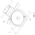
- FIG. 7 is a perspective view illustrating the seat fixing base 12
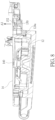
- FIG. 8 is a sectional view illustrating the assembly of the seat 14 and the seat fixing base 12
- FIG. 9 is a perspective view illustrating the seat 14 facing a rear direction of the stroller 1.
- the seat fixing base 12 may have two positioning recesses 124a, 124b, and the seat 14 may further include a positioning member 150 and a second elastic member 152.
- the positioning member 150 is disposed on a bottom of the base 14. Opposite ends of the second elastic member 152 abut against the positioning member 150 and the seat 14.
- the seat 14 faces a front direction of the stroller 1 (as shown in FIG. 1 ).
- the positioning member 150 engages with the other one of the two positioning recesses 124a, 124b
- the seat 14 faces a rear direction of the stroller 1 (as shown in FIG. 9 ).
- the positioning member 150 is configured to cooperate with the two positioning recesses 124a, 124b to orient the seat 14 to face the front direction of the stroller 1 or orient the seat 14 to face the rear direction of the stroller 1.
- the positioning member 150 engages with the positioning recess 124a the seat 14 faces the front direction of the stroller 1.
- the positioning recess 124b the seat 14 faces the rear direction of the stroller 1.
- the invention may adjust the positions of the two positioning recesses 124a, 124b to orient the seat 14 to face other directions of the stroller 1, e.g.
- the invention may further add other positioning recesses to the seat fixing base 12, such that the seat 14 may face more different directions of the stroller 1.
- the positioning member 150 engages with the positioning recess 124a, such that the seat 14 cannot rotate with respect to the seat fixing base 12.
- the user may press the positioning member 150 in a direction of an arrow A3, such that the positioning member 150 disengages from the positioning recess 124a.
- the user may rotate the seat 14 to adjust an orientation of the seat 14.
- the positioning member 150 compresses the second elastic member 152.
- an elastic force generated by the second elastic member 152 pushes the positioning member 150, such that the positioning member 150 returns in a reversed direction of the arrow A3 and then the positioning member 150 engages with the positioning recess 124a or 124b.
- the frame of the invention is equipped with the seat fixing base with the engaging structure.
- the engaging members of the seat engage with the engaging structure of the seat fixing base
- the seat is restrained on the seat fixing base.
- a user may press the unlock button by one hand.
- the unlock button drives the engaging members to disengage from the engaging structure, such that the seat is able to be detached from the seat fixing base.
- the invention may dispose the webbing on the upper surface of the seat.
- the user may press the unlock button of the seat by a thumb and pull the webbing upward by other fingers, so as to detach the seat from the seat fixing base. Accordingly, the user may detach the seat by one hand.
- the operation is convenient and the structure is simple.
Landscapes
- Engineering & Computer Science (AREA)
- Chemical & Material Sciences (AREA)
- Combustion & Propulsion (AREA)
- Transportation (AREA)
- Mechanical Engineering (AREA)
- Health & Medical Sciences (AREA)
- Public Health (AREA)
- Carriages For Children, Sleds, And Other Hand-Operated Vehicles (AREA)
- Led Devices (AREA)
Description
- The present invention relates to a stroller, particularly a stroller with a seat capable of being detached conveniently.
- A stroller is a tool used by parents to carry babies or children when they go shopping. In general, a seat of a conventional stroller is detachable to facilitate storage or transportation. However, a detachable structure of the conventional seat is complicated and a user usually needs to use both hands to remove the seat.
-
DE 10 2014 114 413 B3 describes a child car seat with means for quick removal. For this purpose, a plate is arranged on the frame of a stroller. Slidably moveable sets and an operating lever are mounted on the plate. A rotating disc is arranged below the plate. The operating lever controls a rotation of the rotating disc. The amount of movement of the rotating disc adapts to the slidably moveable sets, such that a telescopic movement of the slidably moveable sets is controlled by the rotation of the rotating disc. For this purpose, the rotating disc is equipped with protruding stops each comprising a second inclined surface, pushing against a first inclined surface at the bottom side of a sliding element of the slidably moveable sets. - The present invention aims at providing a stroller with a seat capable of being detached conveniently, thereby resolving the aforesaid problems.
- This is achieved by a stroller according to
claim 1. The dependent claims pertain to corresponding further developments and improvements. - As will be seen more clearly from the detailed description following below, the claimed stroller includes a frame, a seat fixing base and a seat. The seat fixing base is disposed on the frame. The seat fixing base has an engaging structure. The seat includes an unlock button and a plurality of engaging members. The unlock button abuts against the engaging members. The engaging members engage with the engaging structure to restrain the seat on the seat fixing base. When the unlock button is pressed, the unlock button drives the engaging members to disengage from the engaging structure, such that the seat is able to be detached from the seat fixing base.
- Preferably, the engaging structure is a ring-shaped recess and the engaging members engage with the ring-shaped recess to rotatably restrain the seat on the seat fixing base.
- Preferably, the seat further includes a plurality of first elastic members and a pillar, the engaging members surround the pillar, and opposite ends of each of the first elastic members abut against a corresponding one of the engaging members and the pillar respectively.
- Preferably, the seat fixing base has a protrusion and the pillar has a groove. When the seat is disposed on the seat fixing base, the protrusion is inserted into the groove.
- Preferably, the unlock button has a guiding groove, the pillar has a guiding portion, and the guiding portion is inserted into the guiding groove.
- Preferably, the unlock button has a first inclined surface, each of the engaging members has a second inclined surface, and the first inclined surface abuts against the second inclined surface of each of the engaging members. When the unlock button is pressed, the first inclined surface pushes the second inclined surface of each of the engaging members to drive each of the engaging members to disengage from the engaging structure.
- Preferably, the seat fixing base has two positioning recesses and the seat further includes a positioning member. When the positioning member engages with one of the two positioning recesses, the seat faces a front direction of the stroller. When the positioning member engages with the other one of the two positioning recesses, the seat faces a rear direction of the stroller.
- Preferably, the seat further includes a second elastic member and opposite ends of the second elastic member abut against the positioning member and the seat.
- Preferably, the seat further includes a webbing and the webbing is disposed on an upper surface of the seat.
- Preferably, a moving direction of each of the engaging members is perpendicular to a pressing direction of the unlock button.
- As mentioned in the above, the frame of the invention is equipped with the seat fixing base with the engaging structure. When the engaging members of the seat engage with the engaging structure of the seat fixing base, the seat is restrained on the seat fixing base. To detach the seat, a user may press the unlock button by one hand. When the unlock button is pressed, the unlock button drives the engaging members to disengage from the engaging structure, such that the seat is able to be detached from the seat fixing base. Furthermore, the invention may dispose the webbing on the upper surface of the seat. To detach the seat, the user may press the unlock button of the seat by a thumb and pull the webbing upward by other fingers, so as to detach the seat from the seat fixing base. Accordingly, the user may detach the seat by one hand. The operation is convenient and the structure is simple.
- In the following, the invention is further illustrated by way of example, taking reference to the accompanying drawings thereof:
-
FIG. 1 is a perspective view illustrating a stroller according to an embodiment of the invention, -
FIG. 2 is a perspective view illustrating the stroller shown inFIG. 1 without a seat, -
FIG. 3 is a perspective view illustrating the seat shown inFIG. 1 from another viewing angle, -
FIG. 4 is a sectional view illustrating an assembly of the seat and a seat fixing base, -
FIG. 5 is a perspective view illustrating the seat according to another embodiment of the invention, -
FIG. 6 is a perspective view illustrating the assembly of the seat and the seat fixing base from another viewing angle, -
FIG. 7 is a perspective view illustrating the seat fixing base, -
FIG. 8 is a sectional view illustrating the assembly of the seat and the seat fixing base, and -
FIG. 9 is a perspective view illustrating the seat facing a rear direction of the stroller. - Referring to
FIGs. 1 to 4 ,FIG. 1 is a perspective view illustrating astroller 1 according to an embodiment of the invention,FIG. 2 is a perspective view illustrating thestroller 1 shown inFIG. 1 without aseat 14,FIG. 3 is a perspective view illustrating theseat 14 shown inFIG. 1 from another viewing angle, andFIG. 4 is a sectional view illustrating an assembly of theseat 14 and aseat fixing base 12. - As shown in
FIGs. 1 and2 , thestroller 1 includes aframe 10, aseat fixing base 12 and aseat 14. Theseat fixing base 12 is disposed on theframe 10 and theseat 14 is detachably disposed on theseat fixing base 12. As shown inFIGs. 2 and4 , theseat fixing base 12 has anengaging structure 120. As shown inFIGs. 1 ,3 and4 , theseat 14 includes anunlock button 140 and a plurality ofengaging members 142, wherein theunlock button 140 abuts against theengaging members 142. In this embodiment, theseat 14 may include fourengaging members 142, but the invention is not so limited. The number of theengaging members 142 may be determined according to practical applications. - As shown in
FIG. 4 , when theseat 14 is disposed on theseat fixing base 12, theengaging members 142 engage with theengaging structure 120 to restrain theseat 14 on theseat fixing base 12. When a user wants to detach theseat 14, the user may press theunlock button 140 in a direction of an arrow A1. When theunlock button 140 is pressed, theunlock button 140 drives the engagingmembers 142 to move in a direction of an arrow A2. At this time, the engagingmembers 142 disengage from the engagingstructure 120, such that theseat 14 is able to be detached from theseat fixing base 12. In this embodiment, a moving direction of each of the engaging members 142 (i.e. the direction of the arrow A2) is perpendicular to a pressing direction of the unlock button 140 (i.e. the direction of the arrow A1), but the invention is not so limited. - As shown in
FIG. 2 , the engagingstructure 120 of theseat fixing base 12 is a ring-shaped recess. Thus, the engagingmembers 142 engage with the ring-shaped recess (i.e. the engaging structure 120) to rotatably restrain theseat 14 on theseat fixing base 12. For further explanation, the engagingmembers 142 may freely move within the ring-shaped recess, such that theseat 14 may rotate 360 degrees with respect to theseat fixing base 12. At the same time, since the engagingmembers 142 engage with the engagingstructure 120, theseat 14 is restrained on theseat fixing base 12 while rotating, such that theseat 14 will rotate more stable. - As shown in
FIG. 4 , theseat 14 may further include a plurality of firstelastic members 144 and apillar 146. As shown inFIG. 3 , the engagingmembers 142 surround thepillar 146. As shown inFIG. 4 , opposite ends of each of the firstelastic members 144 abut against a corresponding one of the engagingmembers 142 and thepillar 146 respectively. When theunlock button 140 is pressed to drive the engagingmembers 142 to move in the direction of the arrow A2, each of the engagingmembers 142 compresses the firstelastic member 144. When theunlock button 140 is released, an elastic force generated by the firstelastic member 144 pushes the engagingmember 142, such that the engagingmember 142 returns in a reversed direction of the arrow A2. At the same time, the engagingmember 142 pushes theunlock button 140, such that theunlock button 140 returns in a reversed direction of the arrow A1. - As shown in
FIG. 4 , theunlock button 140 may have a firstinclined surface 1400 and each of the engagingmembers 142 may have a secondinclined surface 1420, wherein the firstinclined surface 1400 abuts against the secondinclined surface 1420 of each of the engagingmembers 142. Thus, when theunlock button 140 is pressed, the firstinclined surface 1400 of theunlock button 140 pushes the secondinclined surface 1420 of each of the engagingmembers 142, so as to drive each of the engagingmembers 142 to move in the direction of the arrow A2 to disengage from the engagingstructure 120 of theseat fixing base 12. When theunlock button 140 is released, the secondinclined surface 1420 of each of the engagingmembers 142 pushes the firstinclined surface 1400 of theunlock button 140, such that theunlock button 140 returns in the direction of the arrow A1. - As shown in
FIG. 4 , an inner side of theunlock button 140 may have a guidinggroove 1402 and a top of thepillar 146 may have a guidingportion 1460. The guidingportion 1460 is inserted into the guidinggroove 1402, such that theunlock button 140 may keep moving linearly with respect to thepillar 146. - As shown in
FIGs. 2 to 4 , theseat fixing base 12 may have aprotrusion 122 and an outer side of thepillar 146 of theseat 14 may have agroove 1462. A user may align thegroove 1462 of theseat 14 with theprotrusion 122 of theseat fixing base 12 to dispose theseat 14 on theseat fixing base 12. When theseat 14 is disposed on theseat fixing base 12, theprotrusion 122 is inserted into thegroove 1462. Thus, the user may align theseat 14 with theseat fixing base 12 by the cooperation between theprotrusion 122 and thegroove 1462, so as to facilitate the installation of theseat 14. - Referring to
FIG. 5, FIG. 5 is a perspective view illustrating theseat 14 according to another embodiment of the invention. As shown inFIG. 5 , theseat 14 may further include awebbing 148, wherein thewebbing 148 is disposed on an upper surface of theseat 14. To detach theseat 14, the user may press theunlock button 140 of theseat 14 by a thumb and pull thewebbing 148 upward by other fingers, so as to detach theseat 14 from the aforesaidseat fixing base 12. Accordingly, the user may detach theseat 14 by one hand. The operation is convenient and the structure is simple. - Referring to
FIGs. 6 to 9 ,FIG. 6 is a perspective view illustrating the assembly of theseat 14 and theseat fixing base 12 from another viewing angle,FIG. 7 is a perspective view illustrating theseat fixing base 12,FIG. 8 is a sectional view illustrating the assembly of theseat 14 and theseat fixing base 12, andFIG. 9 is a perspective view illustrating theseat 14 facing a rear direction of thestroller 1. - As shown in
FIGs. 6 to 8 , theseat fixing base 12 may have twopositioning recesses seat 14 may further include apositioning member 150 and a secondelastic member 152. The positioningmember 150 is disposed on a bottom of thebase 14. Opposite ends of the secondelastic member 152 abut against the positioningmember 150 and theseat 14. When thepositioning member 150 engages with one of the twopositioning recesses seat 14 faces a front direction of the stroller 1 (as shown inFIG. 1 ). When thepositioning member 150 engages with the other one of the twopositioning recesses seat 14 faces a rear direction of the stroller 1 (as shown inFIG. 9 ). In other words, the positioningmember 150 is configured to cooperate with the twopositioning recesses seat 14 to face the front direction of thestroller 1 or orient theseat 14 to face the rear direction of thestroller 1. In this embodiment, when thepositioning member 150 engages with thepositioning recess 124a, theseat 14 faces the front direction of thestroller 1. When thepositioning member 150 engages with thepositioning recess 124b, theseat 14 faces the rear direction of thestroller 1. It should be noted that the invention may adjust the positions of the twopositioning recesses seat 14 to face other directions of thestroller 1, e.g. orient theseat 14 to face a left direction of thestroller 1 or orient theseat 14 to face a right direction of thestroller 1. Needless to say, in addition to the twopositioning recesses seat fixing base 12, such that theseat 14 may face more different directions of thestroller 1. - As shown in
FIG. 8 , the positioningmember 150 engages with thepositioning recess 124a, such that theseat 14 cannot rotate with respect to theseat fixing base 12. The user may press the positioningmember 150 in a direction of an arrow A3, such that thepositioning member 150 disengages from thepositioning recess 124a. At this time, the user may rotate theseat 14 to adjust an orientation of theseat 14. When thepositioning member 150 is pressed to move in the direction of the arrow A3, the positioningmember 150 compresses the secondelastic member 152. When thepositioning member 150 is released and thepositioning member 150 is aligned with thepositioning recess elastic member 152 pushes thepositioning member 150, such that thepositioning member 150 returns in a reversed direction of the arrow A3 and then thepositioning member 150 engages with thepositioning recess - As mentioned in the above, the frame of the invention is equipped with the seat fixing base with the engaging structure. When the engaging members of the seat engage with the engaging structure of the seat fixing base, the seat is restrained on the seat fixing base. To detach the seat, a user may press the unlock button by one hand. When the unlock button is pressed, the unlock button drives the engaging members to disengage from the engaging structure, such that the seat is able to be detached from the seat fixing base. Furthermore, the invention may dispose the webbing on the upper surface of the seat. To detach the seat, the user may press the unlock button of the seat by a thumb and pull the webbing upward by other fingers, so as to detach the seat from the seat fixing base. Accordingly, the user may detach the seat by one hand. The operation is convenient and the structure is simple.
Claims (10)
- A stroller (1), comprising:a frame (10);a seat fixing base (12) disposed on the frame (10), the seat fixing base (12) having an engaging structure (120); anda seat (14) comprising an unlock button (140) and a plurality of engaging members (142), the unlock button (140) abutting against the engaging members (142);wherein the engaging members (142) engage with the engaging structure (120) to restrain the seat (14) on the seat fixing base (12); when the unlock button (140) is pressed, the unlock button (140) drives the engaging members (142) to disengage from the engaging structure (120), such that the seat (14) is able to be detached from the seat fixing base (12).
- The stroller (1) of claim 1, further characterized in that the engaging structure (120) is a ring-shaped recess and the engaging members (142) engage with the ring-shaped recess to rotatably restrain the seat (14) on the seat fixing base (12).
- The stroller (1) of claim 1 or 2, further characterized in that the seat (14) further comprises a plurality of first elastic members (144) and a pillar (146), the engaging members (142) surround the pillar (146), and opposite ends of each of the first elastic members (144) abut against a corresponding one of the engaging members (142) and the pillar (146), respectively.
- The stroller (1) of claim 3, further characterized in that the seat fixing base (12) has a protrusion (122) and the pillar (146) has a groove (1462); wherein, when the seat (14) is disposed on the seat fixing base (12), the protrusion (122) is inserted into the groove (1462).
- The stroller (1) of claim 3 or 4, further characterized in that the unlock button (140) has a guiding groove (1402), the pillar (146) has a guiding portion (1460), and the guiding portion (1460) is inserted into the guiding groove (1402).
- The stroller (1) of any of the preceding claims, further characterized in that the unlock button (140) has a first inclined surface (1400), each of the engaging members (142) has a second inclined surface (1420), and the first inclined surface (1400) abuts against the second inclined surface (1420) of each of the engaging members (142); wherein, when the unlock button (140) is pressed, the first inclined surface (1400) pushes the second inclined surface (1420) of each of the engaging members (142) to drive each of the engaging members (142) to disengage from the engaging structure (120).
- The stroller (1) of any of the preceding claims, further characterized in that the seat fixing base (12) has two positioning recesses (124a, 124b) and the seat (14) further comprises a positioning member (150); wherein, when the positioning member (150) engages with one of the two positioning recesses (124a, 124b), the seat (14) faces a front direction of the stroller (1); and when the positioning member (150) engages with the other one of the two positioning recesses (124a, 124b), the seat (14) faces a rear direction of the stroller (1).
- The stroller (1) of claim 7, further characterized in that the seat (14) further comprises a second elastic member (152), and opposite ends of the second elastic member (152) abut against the positioning member (150) and the seat (14).
- The stroller (1) of any of the preceding claims,further characterized in that the seat (14) further comprises a webbing (148), and the webbing (148) is disposed on an upper surface of the seat (14).
- The stroller (1) of any of the preceding claims, further characterized in that a moving direction of each of the engaging members (142) is perpendicular to a pressing direction of the unlock button (140).
Applications Claiming Priority (2)
| Application Number | Priority Date | Filing Date | Title |
|---|---|---|---|
| CN202110664154.0A CN115476907B (en) | 2021-06-16 | 2021-06-16 | Baby carriage |
| PCT/EP2022/066420 WO2022263571A1 (en) | 2021-06-16 | 2022-06-15 | Stroller |
Publications (2)
| Publication Number | Publication Date |
|---|---|
| EP4308435A1 EP4308435A1 (en) | 2024-01-24 |
| EP4308435B1 true EP4308435B1 (en) | 2025-02-26 |
Family
ID=82218385
Family Applications (1)
| Application Number | Title | Priority Date | Filing Date |
|---|---|---|---|
| EP22733959.5A Active EP4308435B1 (en) | 2021-06-16 | 2022-06-15 | Stroller |
Country Status (8)
| Country | Link |
|---|---|
| US (1) | US20240308567A1 (en) |
| EP (1) | EP4308435B1 (en) |
| JP (2) | JP7686092B2 (en) |
| CN (2) | CN120902813A (en) |
| DE (1) | DE112022003104T5 (en) |
| ES (1) | ES3026127T3 (en) |
| TW (1) | TWI815501B (en) |
| WO (1) | WO2022263571A1 (en) |
Citations (9)
| Publication number | Priority date | Publication date | Assignee | Title |
|---|---|---|---|---|
| CN201183515Y (en) | 2008-02-05 | 2009-01-21 | 好孩子儿童用品有限公司 | Seat installation structure of children's stroller |
| CN102219026B (en) | 2010-02-23 | 2013-02-27 | 明门香港股份有限公司 | Baby seat capable of adjusting rotation angle and baby trolley |
| DE102014114413B3 (en) | 2014-10-03 | 2016-02-25 | Pao-Hsien Cheng | Device for quickly releasing a stroller seat |
| CN105501282A (en) | 2014-09-22 | 2016-04-20 | 程宝贤 | Seat quick release mechanism for baby stroller |
| EP2727498B1 (en) | 2004-05-17 | 2016-06-22 | Orbit Baby, Inc. | Modular child restraint system |
| WO2018022893A1 (en) | 2016-07-27 | 2018-02-01 | Kolcraft Enterprises, Inc. | Strollers with removable seats and related methods |
| CN211893372U (en) | 2020-03-26 | 2020-11-10 | 唐新华 | A baby carriage skeleton |
| DE202019105127U1 (en) | 2019-09-17 | 2020-12-18 | Cybex Gmbh | stroller |
| CN112810688A (en) | 2021-02-25 | 2021-05-18 | 罗瑞运动用品(昆山)有限公司 | Baby carriage |
Family Cites Families (8)
| Publication number | Priority date | Publication date | Assignee | Title |
|---|---|---|---|---|
| CN101670796B (en) * | 2008-09-10 | 2011-11-16 | 宝钜实业股份有限公司 | Child safety seat |
| TWM530264U (en) * | 2016-05-17 | 2016-10-11 | 聖約翰科技大學 | Improved structure of baby stroller |
| CN108068871B (en) * | 2016-11-17 | 2020-06-09 | 明门香港股份有限公司 | Baby carriage |
| CN207292106U (en) * | 2017-09-30 | 2018-05-01 | 嘉兴小虎子车业有限公司 | A kind of bench rotation and detaching structure on perambulator |
| CN109017956A (en) * | 2018-09-18 | 2018-12-18 | 中山市西区青原贸易代理服务部 | Cart frame |
| CN111409688B (en) * | 2020-04-09 | 2025-02-25 | 上海贝育信息科技有限公司 | 360 degree rotating seat for strollers |
| CN213008318U (en) * | 2020-05-28 | 2021-04-20 | 徐江林 | Baby carriage with sliding seat |
| CN212980325U (en) * | 2020-08-22 | 2021-04-16 | 方应芳良 | Rotary adjusting mechanism of child seat |
-
2021
- 2021-06-16 CN CN202511048442.8A patent/CN120902813A/en active Pending
- 2021-06-16 CN CN202110664154.0A patent/CN115476907B/en active Active
-
2022
- 2022-06-15 US US18/570,849 patent/US20240308567A1/en active Pending
- 2022-06-15 ES ES22733959T patent/ES3026127T3/en active Active
- 2022-06-15 TW TW111122125A patent/TWI815501B/en active
- 2022-06-15 WO PCT/EP2022/066420 patent/WO2022263571A1/en not_active Ceased
- 2022-06-15 EP EP22733959.5A patent/EP4308435B1/en active Active
- 2022-06-15 DE DE112022003104.2T patent/DE112022003104T5/en active Pending
- 2022-06-15 JP JP2023576376A patent/JP7686092B2/en active Active
-
2025
- 2025-05-20 JP JP2025083807A patent/JP2025109903A/en active Pending
Patent Citations (9)
| Publication number | Priority date | Publication date | Assignee | Title |
|---|---|---|---|---|
| EP2727498B1 (en) | 2004-05-17 | 2016-06-22 | Orbit Baby, Inc. | Modular child restraint system |
| CN201183515Y (en) | 2008-02-05 | 2009-01-21 | 好孩子儿童用品有限公司 | Seat installation structure of children's stroller |
| CN102219026B (en) | 2010-02-23 | 2013-02-27 | 明门香港股份有限公司 | Baby seat capable of adjusting rotation angle and baby trolley |
| CN105501282A (en) | 2014-09-22 | 2016-04-20 | 程宝贤 | Seat quick release mechanism for baby stroller |
| DE102014114413B3 (en) | 2014-10-03 | 2016-02-25 | Pao-Hsien Cheng | Device for quickly releasing a stroller seat |
| WO2018022893A1 (en) | 2016-07-27 | 2018-02-01 | Kolcraft Enterprises, Inc. | Strollers with removable seats and related methods |
| DE202019105127U1 (en) | 2019-09-17 | 2020-12-18 | Cybex Gmbh | stroller |
| CN211893372U (en) | 2020-03-26 | 2020-11-10 | 唐新华 | A baby carriage skeleton |
| CN112810688A (en) | 2021-02-25 | 2021-05-18 | 罗瑞运动用品(昆山)有限公司 | Baby carriage |
Non-Patent Citations (5)
| Title |
|---|
| CYBEX_GLOBAL: "CYBEX EEZY S Twist Tutorial", 2 May 2018 (2018-05-02), XP093341981, Retrieved from the Internet <URL:https://www.youtube.com/watch?v=pKq_tPuQ36A> |
| D10a - Rechnung 03.01.2020 (MB2a) |
| D10b - Rechnung 03.01.2020 (MB2b) |
| ELTERNCHECKER: "CYBEX GOLD EEZY S TWIST - UNBOXING & REVIEW 2018/2019", 4 September 2018 (2018-09-04), XP093341980, Retrieved from the Internet <URL:https://www.youtube.com/watch?v=VxZqBxA5uVg> |
| GROWINGYOURBABY: "NEW! CYBEX EEZY S TWIST STROLLER - ABC KIDS EXPO 2017", 20 October 2017 (2017-10-20), XP093341984, Retrieved from the Internet <URL:https://www.youtube.com/watch?v=0yWCuqJBYSA> |
Also Published As
| Publication number | Publication date |
|---|---|
| DE112022003104T5 (en) | 2024-03-28 |
| CN115476907A (en) | 2022-12-16 |
| JP7686092B2 (en) | 2025-05-30 |
| TW202300372A (en) | 2023-01-01 |
| ES3026127T3 (en) | 2025-06-10 |
| US20240308567A1 (en) | 2024-09-19 |
| JP2024520858A (en) | 2024-05-24 |
| WO2022263571A1 (en) | 2022-12-22 |
| CN120902813A (en) | 2025-11-07 |
| CN115476907B (en) | 2025-08-19 |
| EP4308435A1 (en) | 2024-01-24 |
| TWI815501B (en) | 2023-09-11 |
| JP2025109903A (en) | 2025-07-25 |
Similar Documents
| Publication | Publication Date | Title |
|---|---|---|
| CN102100463B (en) | Infant bearing device and operating mechanism with safety lock | |
| EP4253192B1 (en) | Unlock device and stroller | |
| US4180716A (en) | Switch having lock-off and lock-on | |
| TWI750820B (en) | Backrest locking mechanism and child safety seat therewith | |
| AU665444B2 (en) | Holding device for portable equipment | |
| EP4308435B1 (en) | Stroller | |
| US20250002068A1 (en) | Folding joint and child carrier | |
| EP4257422A1 (en) | Multifunctional baby carrycot | |
| TWI753646B (en) | Handle adjusting mechanism and child carrier therewith | |
| EP4429933B1 (en) | Locking device, locking structure, child carrier and seat of child carrier | |
| US6332596B1 (en) | Device for releasably mounting wrist support to computer keyboard | |
| CN220720875U (en) | Child seat capable of rotating by one hand | |
| JP2012179695A (en) | Power tool | |
| WO2024213722A2 (en) | Frame, seat locking device, and stroller | |
| CN201899188U (en) | toddler seat | |
| JP2004146514A (en) | Angle retaining mechanism and apparatus using the same |
Legal Events
| Date | Code | Title | Description |
|---|---|---|---|
| STAA | Information on the status of an ep patent application or granted ep patent |
Free format text: STATUS: UNKNOWN |
|
| STAA | Information on the status of an ep patent application or granted ep patent |
Free format text: STATUS: THE INTERNATIONAL PUBLICATION HAS BEEN MADE |
|
| PUAI | Public reference made under article 153(3) epc to a published international application that has entered the european phase |
Free format text: ORIGINAL CODE: 0009012 |
|
| STAA | Information on the status of an ep patent application or granted ep patent |
Free format text: STATUS: REQUEST FOR EXAMINATION WAS MADE |
|
| 17P | Request for examination filed |
Effective date: 20231019 |
|
| AK | Designated contracting states |
Kind code of ref document: A1 Designated state(s): AL AT BE BG CH CY CZ DE DK EE ES FI FR GB GR HR HU IE IS IT LI LT LU LV MC MK MT NL NO PL PT RO RS SE SI SK SM TR |
|
| GRAP | Despatch of communication of intention to grant a patent |
Free format text: ORIGINAL CODE: EPIDOSNIGR1 |
|
| STAA | Information on the status of an ep patent application or granted ep patent |
Free format text: STATUS: GRANT OF PATENT IS INTENDED |
|
| DAV | Request for validation of the european patent (deleted) | ||
| DAX | Request for extension of the european patent (deleted) | ||
| INTG | Intention to grant announced |
Effective date: 20240912 |
|
| P01 | Opt-out of the competence of the unified patent court (upc) registered |
Free format text: CASE NUMBER: APP_56712/2024 Effective date: 20241017 |
|
| GRAS | Grant fee paid |
Free format text: ORIGINAL CODE: EPIDOSNIGR3 |
|
| GRAA | (expected) grant |
Free format text: ORIGINAL CODE: 0009210 |
|
| STAA | Information on the status of an ep patent application or granted ep patent |
Free format text: STATUS: THE PATENT HAS BEEN GRANTED |
|
| AK | Designated contracting states |
Kind code of ref document: B1 Designated state(s): AL AT BE BG CH CY CZ DE DK EE ES FI FR GB GR HR HU IE IS IT LI LT LU LV MC MK MT NL NO PL PT RO RS SE SI SK SM TR |
|
| REG | Reference to a national code |
Ref country code: GB Ref legal event code: FG4D |
|
| REG | Reference to a national code |
Ref country code: CH Ref legal event code: EP |
|
| REG | Reference to a national code |
Ref country code: DE Ref legal event code: R096 Ref document number: 602022011195 Country of ref document: DE |
|
| REG | Reference to a national code |
Ref country code: IE Ref legal event code: FG4D |
|
| REG | Reference to a national code |
Ref country code: NL Ref legal event code: FP |
|
| REG | Reference to a national code |
Ref country code: ES Ref legal event code: FG2A Ref document number: 3026127 Country of ref document: ES Kind code of ref document: T3 Effective date: 20250610 |
|
| PG25 | Lapsed in a contracting state [announced via postgrant information from national office to epo] |
Ref country code: RS Free format text: LAPSE BECAUSE OF FAILURE TO SUBMIT A TRANSLATION OF THE DESCRIPTION OR TO PAY THE FEE WITHIN THE PRESCRIBED TIME-LIMIT Effective date: 20250526 |
|
| PG25 | Lapsed in a contracting state [announced via postgrant information from national office to epo] |
Ref country code: FI Free format text: LAPSE BECAUSE OF FAILURE TO SUBMIT A TRANSLATION OF THE DESCRIPTION OR TO PAY THE FEE WITHIN THE PRESCRIBED TIME-LIMIT Effective date: 20250226 |
|
| PG25 | Lapsed in a contracting state [announced via postgrant information from national office to epo] |
Ref country code: PL Free format text: LAPSE BECAUSE OF FAILURE TO SUBMIT A TRANSLATION OF THE DESCRIPTION OR TO PAY THE FEE WITHIN THE PRESCRIBED TIME-LIMIT Effective date: 20250226 |
|
| PGFP | Annual fee paid to national office [announced via postgrant information from national office to epo] |
Ref country code: DE Payment date: 20250422 Year of fee payment: 4 |
|
| REG | Reference to a national code |
Ref country code: LT Ref legal event code: MG9D |
|
| PG25 | Lapsed in a contracting state [announced via postgrant information from national office to epo] |
Ref country code: NO Free format text: LAPSE BECAUSE OF FAILURE TO SUBMIT A TRANSLATION OF THE DESCRIPTION OR TO PAY THE FEE WITHIN THE PRESCRIBED TIME-LIMIT Effective date: 20250526 Ref country code: IS Free format text: LAPSE BECAUSE OF FAILURE TO SUBMIT A TRANSLATION OF THE DESCRIPTION OR TO PAY THE FEE WITHIN THE PRESCRIBED TIME-LIMIT Effective date: 20250626 |
|
| PGFP | Annual fee paid to national office [announced via postgrant information from national office to epo] |
Ref country code: NL Payment date: 20250618 Year of fee payment: 4 |
|
| PG25 | Lapsed in a contracting state [announced via postgrant information from national office to epo] |
Ref country code: HR Free format text: LAPSE BECAUSE OF FAILURE TO SUBMIT A TRANSLATION OF THE DESCRIPTION OR TO PAY THE FEE WITHIN THE PRESCRIBED TIME-LIMIT Effective date: 20250226 |
|
| PG25 | Lapsed in a contracting state [announced via postgrant information from national office to epo] |
Ref country code: LV Free format text: LAPSE BECAUSE OF FAILURE TO SUBMIT A TRANSLATION OF THE DESCRIPTION OR TO PAY THE FEE WITHIN THE PRESCRIBED TIME-LIMIT Effective date: 20250226 Ref country code: PT Free format text: LAPSE BECAUSE OF FAILURE TO SUBMIT A TRANSLATION OF THE DESCRIPTION OR TO PAY THE FEE WITHIN THE PRESCRIBED TIME-LIMIT Effective date: 20250626 |
|
| PGFP | Annual fee paid to national office [announced via postgrant information from national office to epo] |
Ref country code: FR Payment date: 20250429 Year of fee payment: 4 |
|
| PG25 | Lapsed in a contracting state [announced via postgrant information from national office to epo] |
Ref country code: BG Free format text: LAPSE BECAUSE OF FAILURE TO SUBMIT A TRANSLATION OF THE DESCRIPTION OR TO PAY THE FEE WITHIN THE PRESCRIBED TIME-LIMIT Effective date: 20250226 Ref country code: GR Free format text: LAPSE BECAUSE OF FAILURE TO SUBMIT A TRANSLATION OF THE DESCRIPTION OR TO PAY THE FEE WITHIN THE PRESCRIBED TIME-LIMIT Effective date: 20250527 |
|
| REG | Reference to a national code |
Ref country code: AT Ref legal event code: MK05 Ref document number: 1770392 Country of ref document: AT Kind code of ref document: T Effective date: 20250226 |
|
| PG25 | Lapsed in a contracting state [announced via postgrant information from national office to epo] |
Ref country code: SE Free format text: LAPSE BECAUSE OF FAILURE TO SUBMIT A TRANSLATION OF THE DESCRIPTION OR TO PAY THE FEE WITHIN THE PRESCRIBED TIME-LIMIT Effective date: 20250226 |
|
| PG25 | Lapsed in a contracting state [announced via postgrant information from national office to epo] |
Ref country code: SM Free format text: LAPSE BECAUSE OF FAILURE TO SUBMIT A TRANSLATION OF THE DESCRIPTION OR TO PAY THE FEE WITHIN THE PRESCRIBED TIME-LIMIT Effective date: 20250226 |
|
| PGFP | Annual fee paid to national office [announced via postgrant information from national office to epo] |
Ref country code: ES Payment date: 20250701 Year of fee payment: 4 |
|
| PG25 | Lapsed in a contracting state [announced via postgrant information from national office to epo] |
Ref country code: DK Free format text: LAPSE BECAUSE OF FAILURE TO SUBMIT A TRANSLATION OF THE DESCRIPTION OR TO PAY THE FEE WITHIN THE PRESCRIBED TIME-LIMIT Effective date: 20250226 |
|
| PG25 | Lapsed in a contracting state [announced via postgrant information from national office to epo] |
Ref country code: IT Free format text: LAPSE BECAUSE OF FAILURE TO SUBMIT A TRANSLATION OF THE DESCRIPTION OR TO PAY THE FEE WITHIN THE PRESCRIBED TIME-LIMIT Effective date: 20250226 |
|
| PG25 | Lapsed in a contracting state [announced via postgrant information from national office to epo] |
Ref country code: AT Free format text: LAPSE BECAUSE OF FAILURE TO SUBMIT A TRANSLATION OF THE DESCRIPTION OR TO PAY THE FEE WITHIN THE PRESCRIBED TIME-LIMIT Effective date: 20250226 |
|
| PGFP | Annual fee paid to national office [announced via postgrant information from national office to epo] |
Ref country code: CH Payment date: 20250701 Year of fee payment: 4 |
|
| PG25 | Lapsed in a contracting state [announced via postgrant information from national office to epo] |
Ref country code: CZ Free format text: LAPSE BECAUSE OF FAILURE TO SUBMIT A TRANSLATION OF THE DESCRIPTION OR TO PAY THE FEE WITHIN THE PRESCRIBED TIME-LIMIT Effective date: 20250226 Ref country code: EE Free format text: LAPSE BECAUSE OF FAILURE TO SUBMIT A TRANSLATION OF THE DESCRIPTION OR TO PAY THE FEE WITHIN THE PRESCRIBED TIME-LIMIT Effective date: 20250226 |
|
| PG25 | Lapsed in a contracting state [announced via postgrant information from national office to epo] |
Ref country code: RO Free format text: LAPSE BECAUSE OF FAILURE TO SUBMIT A TRANSLATION OF THE DESCRIPTION OR TO PAY THE FEE WITHIN THE PRESCRIBED TIME-LIMIT Effective date: 20250226 |
|
| PG25 | Lapsed in a contracting state [announced via postgrant information from national office to epo] |
Ref country code: SK Free format text: LAPSE BECAUSE OF FAILURE TO SUBMIT A TRANSLATION OF THE DESCRIPTION OR TO PAY THE FEE WITHIN THE PRESCRIBED TIME-LIMIT Effective date: 20250226 |
|
| REG | Reference to a national code |
Ref country code: DE Ref legal event code: R026 Ref document number: 602022011195 Country of ref document: DE |
|
| PLBI | Opposition filed |
Free format text: ORIGINAL CODE: 0009260 |
|
| PLAX | Notice of opposition and request to file observation + time limit sent |
Free format text: ORIGINAL CODE: EPIDOSNOBS2 |
|
| 26 | Opposition filed |
Opponent name: CYBEX GMBH Effective date: 20251126 |
|
| PG25 | Lapsed in a contracting state [announced via postgrant information from national office to epo] |
Ref country code: MC Free format text: LAPSE BECAUSE OF FAILURE TO SUBMIT A TRANSLATION OF THE DESCRIPTION OR TO PAY THE FEE WITHIN THE PRESCRIBED TIME-LIMIT Effective date: 20250226 |
|
| PG25 | Lapsed in a contracting state [announced via postgrant information from national office to epo] |
Ref country code: LU Free format text: LAPSE BECAUSE OF NON-PAYMENT OF DUE FEES Effective date: 20250615 |
|
| REG | Reference to a national code |
Ref country code: BE Ref legal event code: MM Effective date: 20250630 |